Instruction manual. Handheld 3-Axes Stabilizer for Mirrorless Camera & DSLR
|
|
|
- Jodie Butler
- 6 years ago
- Views:
Transcription
1 EN Instruction manual Handheld 3-Axes Stabilizer for Mirrorless Camera & DSLR Pilotfly Technology Co. LTD. Jiafeng S. Rd. No.118,2F-2 Zhubei City, Hsinchu County Taiwan Pilotfly GmbH Wendelsteinstr Augsburg Deutschland

2 Imprint Version English, 2 nd Edition, Pilotfly Copyright This document is protected by copyright. All rights, including those of the whole or partial photo-mechanical reproduction, duplication and spreading (e. g. by means of data processing, to data carriers and data network works) as well as content and technical changes, are left in the course of constant product improvements. 2
3 Dear customer, We thank you for your confidence and wish you a lot of joy and success with your new Pilotfly product. You have decided in favor of a high-quality product with that. The T1 is the next generation of a Two-Hand-Gimbal with newest integrated technology. The 32 bit Alexmos chip with Triple-MCUs and 2 integrated IMU sensors opens all possibilities for your video shooting with your mirrorless or DSLR cameras. The elegant tool-less design, the lightweight Gimbal structure with remote control gives you all the flexibility and versatility you need. You easily can detach the handle and exchange it with the compatible one-hand handle from the Pilotfly-H2. You can hold it with one hand or two hands, you can attach the Gimbal construction to a drone. Depends whatever your passion is to make your video, the Pilotfly-T1 will transform to your needs. The lightweight handle construction consists of carbon fiber material with 4 integrated and removable Li- Ion batteries which provides you an operation time up to 18 hours. Even if you are familiar with handling electronic equipments, please read the instruction manual, because it is an important component of this product. It contains important notes for the safety, the use and the disposal. Familiarize yourself with all hints to the use and the safety items before you use the product. Follow the notes and tips, so that you can use your new product optimally. Only use the product as described and for the indicated fields of application. IMPORTANT AFTER YOU HAVE READ THE INSTRUCTION MANUAL, KEEP IT TOGETHER WITH THE PRODUCT FOR A LATER LOOKING UP. IN CASE YOU GIVE THE PRODUCT TO ANY THIRD PARTY, HAND OVER IT TOGETHER WITH ALL DOCUMENTS! Nevertheless, if you should have problems with your product, please address your enquiry to pilotflyteam@gmail.com (Taiwan) or support@pilotfly.de (Germany). We help you along willingly promptly and give you information about the next steps. Service Adresse Taiwan Pilotfly Technology Co. LTD. Jiafeng South Rd. No.118, 2F-2 Zhubei City, Hsinchu County Taiwan yanherlin@gmail.com Service Adress Germany Pilotfly GmbH Wendelsteinstr Augsburg Deutschland marcus.oswald@pilotfly.de Trademark Proof Bluetooth SIG, Inc. Bluetooth SIG, Inc. All rights reserved. Bluetooth is a registered trademark of Bluetooth SIG, Inc. (Special Interest Group), USA. Google Inc. All rights reserved. The Google logo, Google, Android and Google Play are registered brands of Google Inc. Microsoft Corporation all rights reserved. Microsoft and Windows are registered trademarks of Microsoft Corporation in the United States and/or other countries. Apple Computer Inc. All rights reserved. Macintosh and OSs are registered trademarks of Apple Computer Inc. in the United States and/or other countries. Linux Torvalds all rights reserved. Linux is a registered trademark of Linus Torvalds. All other products and brand names which are mentioned in this manual or in the other documentations to your Pilotfly product are trademarks or registered trademarks of the respective entitled persons. 3
4 Product Overview Components Caution Property damage! All lock screws can be completely removed, pay attention while unscrewing them. Remove camera before unscrewing to prevent it from falling and damages on your equipment. Handle description 4
5 Product Overview Function keys and LED displays on the Bluetooth handle Function! Do not insert the battery in the wrong way. Ensure that + Pole is inside and - Pole is at cap side as illustrated. 5


6 Product Overview Mode button The respective operating mode of your Pilotfly Gimbal can be set using the mode button. The mode button can be assigned different profiles using the SimpleBGC software GUI. A profile is respectively a set of predefined settings such as, for example, different provisions for the following mode, the rotation speed of the individual axes, the initial alignment of the axes, time lapse settings, axis acceleration, control parameters tuned to your camera weight for optimal vibration reduction, parameters for smooth operation, etc.. You can optimize these settings according to your own preferences using the SimpleBGC 32 Bit software GUI 5. Software use for PC/MAC or also using the applicable SimpleBGC Apps for Android or ios. In the table, you can see the pre-set assignment and a description of the settings stored as profile respectively: Operation Function Explanation 1 x tap Follow mode Profile 1 - The pitch and heading direction follows your movements. 2 x tap Lock mode Profile 2 - Pitch and Roll is locked, Yaw follows the target. 3 x tap Head mode Profile 3 - Camera stays in its current orientation. All axes are locked. 4 x tap Follow roll mode Profile 4 Camera follows your movements for all three axes Yaw, Roll and Pitch. 5 x tap Gyro calibration Calibrate Gyro - Starts the Gyro calibration. This is necessary, if Gimbal is slightly drifting. Home / Time-lapse mode button Operation Function Explanation 1 x tap Home move Gimbal will go back to zero position (Home Move) selected mode is active. Long press 2 s Joystick / Time-lapse Switches between joystick and timelapse mode. 6

7 Product Overview! If you are using optionally the Pilotfly H2 1-Hand Holder, which is available as sparepart. Please refer the instruction manual of the H2 how you can use the different modes with the H2 1-Hand Holder.! You can use the T1 also in upright mode or briefcase position. The new position is recognized automatically. All above mentioned modes can also be selcted in these conditions. Only home move is then not supported. Acoustic signals - Buzzer Action / Event Power on Initialization in process Calibrating Low batteries Sound sequence Initialization sound sequence during system boot up and initialisation Be~Bi~Li~Bi~Li Dn~Dn~Dn~Dn~Dn~Dn Continuous cricket sound Use the SimpleBGC 32 Bit Software GUI to change the volume oft he buzzer or to deactivte the buzzer 5.9 Extended settings for advanced users View Level Advanced 5.12 Buzzer and LED settings. Scope of delivery 1 x Pilotfly T1 Gimbal 1 x Pilotfly Tuning Stand 1 x Adapter plate 1 x Mini Tripod 1 x Carrying case 1 x 4-Bay charger 1 x Battery Set (4x Li-Ion / 1 x Li-Ion) 1 x USB cable 1 x Quick Start Guide 7
8 Product Overview Technical data Technology Communication interface Operating system Number of IMU sensors Power supply: Batteries 32 bit Alexmos with Triple-MCU technology Integrated Bluetooth Version 4.0 / 2402 MHz to 2480 MHz Max. transmitting power 2,5 mw/ Range ca. 10 m Windows, MAC OSX, LINUX and App Android, ios Integrated Triple-MCUs with 2 IMU sensors 4x 3,7 V 2800 mah Lipo rechargeable batteries Battery endurance Voltage range ca. 18 hours 13,2 V 16,8 V Li-Ion Battery Charger Input: AC 100 V ~ 240 V 50 Hz/ 60 Hz 0,15 A; DC 5 V 2 A (via USB) Output: DC 4,2 V 650 ma x 4; Model: SKLC Movement range YAW 360 ROLL Left 100, Right 240 PITCH Top 220, Down 100 Accuracy min. ± 0,01 max. ± 0,04 Unladen weight Max. additional load (Motor payload) Dimensions Operating conditions ca.1450 g (including batteries) 2,2 Kg 330 x 150 x 40 mm Temperature: -10 C to max. +40 C Humidity: % Special features Supported temperature accelerometer calibration 5 user-configurable modes Pitch and YAW angle can be controlled by 4-way-joystick Adaptive PID-algorithm for preventing vibrations in big angles "ACC low-pass filter" to improve the stability System beep sound alert for low voltage, mode change, calibration Wireless Bluetooth remote control with Android or ios App Specification Bluetooth Handle/Joystick Bluetooth 4.0 Weight 100 g 1x 3,7V 800 mah Li-ion rechargeable battery Usage time approx. 6 hours Wireless range approx. 3m 8
9 Table of contents IMPORTANT SAFETY INSTRUCTIONS MEANING OF THE SYMBOLS USED IN THIS INSTRUCTION MANUAL INTENDED USE POSSIBLE DANGERS FOR CERTAIN PERSON GROUPS PERSONAL RIGHT AT THE PICTURE OF ONE'S OWN THE USE AT CERTAIN PLACES AND ENVIRONMENTAL CONDITIONS BATTERY CHARGER AND OPERATING CONDITIONS PRECAUTIONS AT HANDLING WITH LI-ION BATTERIES SAFE DISPOSAL SETUP AND OPERATING UNPACKING FIRST STEPS ASSEMBLING AND ADJUSTMENT OF THE CAMERA SWITCH ON AND BASIC OPERATING FINE-TUNING USING THE SIMPLEBGC GUI SOFTWARE MAKING A BLUETOOTH CONNECTION PAIRING WITH PC, MAC OR SMARTPHONE (ANDROID, IOS) PAIRING WITH THE BLUETOOTH HANDLE (JOYSTICK) SOFTWARE INSTALLATION INSTALLATION ON WINDOWS INSTALLATION ON LINUX INSTALLATION ON MAC OS INSTALLATION OF THE ANDROID APP USING THE SOFTWARE PC/MAC - OVERVIEW OVERVIEW OF THE SIMPLEBGC SOFTWARE GUI CONNECTING THE GIMBAL WITH THE SIMPLEBGC SOFTWARE GUI SAVING AND LOADING PROFILES ONTO THE COMPUTER WRITING AND READING PROFILES ONTO/FROM THE GIMBAL MAKING A BACKUP WITH THE BACKUP MANAGER CALIBRATING THE GYROMETER CALIBRATING THE ACCELEROMETER BASIC SETTINGS FOR BEGINNERS VIEW LEVEL BASIC RC-Settings (Remote control, Joystick settings) Follow-Mode Service (Assigning the Mode-button, Startup behavior) Firmware Upgrade EXTENDED SETTINGS FOR ADVANCED USERS VIEW LEVEL ADVANCED RC-Settings (Remote control, Joystick settings) Follow-Mode Service (Assigning the Mode-button, Startup behavior) Firmware Upgrade Stabilization (Reducing vibrations)
10 Table of contents Monitoring (Real-Time view of the sensors - raw data) Hardware (Calibration of the gyrometer and accelerometer) Adjustable Variables Scripting FINE-TUNING BY ADJUSTING THE PID SETTINGS ADVANCED Manually optimising the PID control settings Automatically optimize the PID control settings USING THE TIME LAPSE SETTINGS ADVANCED BUZZER AND LED SETTINGS ADVANCED USING THE DIGITAL FILTER (REDUCING RESONANCE) - EXPERT Notch filter Reduce vibrations on certain frequencies Low-pass filter Reduce high-frequency vibrations USING THE ANDROID APP GIMBAL SETTINGS MISC SETTINGS RC SETTINGS FOLLOW MODE MONITORING CONTROL SETTINGS FAILURE / REPAIR MAINTENANCE AND CARE PUT OUT OF OPERATION, STORAGE, TRANSPORT SERVICE EU DECLARATION OF CONFORMITY (DOC)
11 Important Safety Instructions Please read these safety instructions attentively before you take your Pilotfly product into operation to avoid damages to the product and prevent possible injuries. Keep these safety instructions available for all persons who will use this product. 1.1 Meaning of the symbols used in this instruction manual Warning notices are mentioned in the following chapters in the context in which a danger can appear. They are highlighted especially in the following chapters. The safety instructions within this chapter 1 are generally important and therefore aren't highlighted separately. Danger Endangering with a high risk degree which can mean danger to life or a heavy injury in the consequence, if it isn't avoided. Warning Endangering with a middle risk degree which can mean danger to life or a heavy injury in the consequence, if it isn't avoided. Caution Endangering with a low risk degree which can mean minor or moderate injury in the consequence, if it isn't avoided. Caution Danger of damage to property or environmental damage. Highlights tips and information for you. 11
12 Important Safety Instructions 1.2 Intended use This product is provided exclusively for video recordings in the private use. It isn't provided for commercial or industrial use. The delivered battery charger is intended exclusively for the use with the Li-Ion batteries provided with the Pilotfly Gimbal. Every other use isn't as designated. Prior condition for the use as designated is the attention of the notes of this instruction manual. Any liability on the part of the manufacturer for damages which result from a use which is not as designated or caused by unauthorized modifications is excluded. Also use only the accessories specified by the manufacturer. Please pay attention to the local regulations and laws of the country in which you use the Pilotfly Gimbal. 1.3 Possible dangers for certain person groups This device is not designated for the use by children and certain other person groups with restricted physical, sensory or intellectual abilities or lack of experience and/or lack of knowledge. Children and person groups cannot recognize always possible dangers correctly. Therefore pay attention, that children older than 14 years and above mentioned person groups ONLY use the device if they have been supervised by you or a safety responsible person or if they were introduced respectively, but NEVER unattended. children do not play with or clean or open the device unattendedly. You keep away packing foils! There is danger of suffocation. you consider possible dangers for children when you lay the cable, e.g. strangling. 1.4 Personal right at the picture of one's own Pay attention to the restrictions of copyright with regard to filming persons especially at public events, such as exhibitions, stage productions, celebrations, or similar. Even if the photos are for personal use only. The consent of the parents has to be sought especially from minors before capturing a photo. Pay attention to the legal regulations of the country in which you use the device to avoid legal consequences. 12
13 Important Safety Instructions 1.5 The use at certain places and environmental conditions For a safe use of your Pilotfly T1 you have to pay attention, that you use the device only at places which are suitable also for your camera. Implicitely follow the instructions within the instruction manual of the camera which you use with the Gimbal. you follow the instructions of restrictions or embargoes for battery operated equipment at explosive places. Tank areas and areas where the air is containing chemicals or fine particles, e. g. grain, powdered metal. Explosive areas aren't always identified explicitly. you could be distracted when using the device in the current road traffic. This can lead to an accident and you endanger the health of others and yours and you have to expect legal consequences. Therefore use the device at a stationary vehicle. Always notice the legal regulations of the country where you use the device. you operate the device only within the permitted environmental temperature range. Details see at Technical data. you do not expose the device to any strong temperature fluctuations. Atmospheric humidity can condense and lead to electrical short circuits. you do not expose the device to any direct heat sources, such as heaters, or direct solar radiation. Otherwise it can overheat and be damaged irreparably. you avoide the contact with aggressive liquids. you avoide the contact with splashing and dripping water. you never dive it under water or other liquids. 13
14 Important Safety Instructions 1.6 Battery charger and operating conditions For a safe use of your Pilotfly T1 battery charger pay attention, that you make sure that the specified voltage data on the rating label are fitting to the specification of the power socket. you never grasp the power plug with wet hands. If you want to pull the power plug out of the power socket, you always pull directly at the power plug. Never pull at the cable, it could be damaged. Furthermore, never transport the device at the cable. the cable is not modified, jammed, folded, charged by heavy objects, crossed over by vehicle, comes into touch with heat sources or sharp edges. In addition, it mustn't become a stumbling trap. you regularly check the device, the accessories and the cables for damages. If you should notice damages, you may not continue to use the device any more. For repairs send it only to the Pilotfly- Service. you immediately switch off the device, if you notice smoke, unusual noises or smells. Do not continue using it any more before a check was performed by an expert. Send it only to the Pilotfly-Service. you switch the device off and you unplug the power plug from the power socket before you clean or service it. you always pull the power plug out of the power socket at a thunderstorm. At a thunderstorm, the equipment which is attached at the power grid can be damaged. you use the battery charger only indoors and dry surroundings. you do not cover the battery charger to avoid a damage by not allowed temperature rise. the power socket is near by the connected device, so that you easily have access to separate the device from the power grid in case of failure. 14
15 Important Safety Instructions 1.7 Precautions at handling with Li-Ion batteries Li-Ion batteries require special handling. Improper handling can shorten the life time or lead to fire or explosions, bleeding or overheating. Pay attention, that you only use the battery charger which is contained in the scope of delivery for charging the batteries of the Pilotfly T1. Generally, for charging Li-Ion batteries only use battery chargers with a Li-Ion charging program and balancer. Charge the batteries only supervised on a fire-proof pad. you replace the batteries only by an identical or equivalent type. you pull the power plug out of the power socket after finished the charging process. you do not throw the batteries into open fire nor submit heat to it. you do not open, do not disassemble and do not deforme batteries. you do not drop or push batteries. you do not transport or store batteries together with objects made of metal, such as paper clips or hairpins. There is a short circuit if the poles of the batteries come into touch with metal objects. Therefore, use fire protection bags for the storage e.g. protective covers like Lipo-Bags, Lipo-Safety Bags. These are fire-resistant and protect against open fire. In the case of a fire use CO2, powder or foam extinguishers. Do not use water. For storage and for the transportation use the same means. you do not charge batteries next to inflammable media. during longer non-utilization you store the device within the delivered carrier bag at a cool and dry place. Best at environmental temperatures from +15 C to +25 C. Avoid places with extreme temperatures. you absolutely keep the batteries away from children. The cells look like "chewing gum" or "chocolate" in the packing and can be swallowed. In case a cell has been swallowed immediately call a doctor to help. Due to the poisonous substances within the batteries, there is serious danger! Keep the batteries in a way that unauthorized persons have no access, especially not children and animals. batteries getting hot when charging. Never touch hot batteries! Otherwise there is the danger of burnings! you do not exchange batteries in potentially explosive surroundings. Spark blow arising from it can cause an explosion! 15


16 Important Safety Instructions 1.8 Safe disposal Endangering health and environment by batteries! In the Europian Economic Area this symbol indicates that consumers are required by law to return all waste batteries to either a store or another collection point for waste batteries. Waste batteries should never be placed in the household garbage, or anywhere in the environment. This is indicated by the symbol comprising a crossedout wheeled bin that appears on batteries and/or battery packaging. In the interest of facilitating waste battery collection, manufacturers of portable batteries have established a joint collection. Retailers are required by law to take back waste batteries free of charge. In Germany, collection boxes in which consumers can deposit waste portable batteries are available at all stores that sell portable batteries, e.g. supermarket, discounter, drugstore or construction market. Some municipalities take waste batteries back, e.g. via vehicles that make regular collections of hazardous waste, or recycling centres. The legal limit for mercury within button cells is 2 percent (20 grams per kilogram) of mercury, while the limit for all other types of batteries is percent (5 milligrams per kilogram). Portable-battery cadmium content is limited to percent (20 milligrams per kilogram). Batteries used for cordless power tools, emergency or alarm systems emergency lighting, and medical devices are exempt from this limit. For batteries whose mercury, cadmium or lead content exceeds specific limit values, this fact must be indicated on the battery or packaging, below the symbol of the crossed-out whelled bin. Please take care e. g. by taping the individual connection poles that the batteries to be disposed of are unloaded and the connection poles are protected from short circuits. Potential negative consequences to the environment and human health! In the Europian Economic Area this symbol indicates that this product shall not be treated as houshold waste. Instead it has to be taken to an applicable collection point for the recycling of electrical and electronic equipment. By ensuring this product is dispoesed of correctly, you will help prevent potential negative consequences to the environment and human health, which could otherwise be caused by inappropriate waste handling of this product. In the Europian Economic Area this symbol indicates that you should dispose the packing materials environmentally sensible according to the local regulations. 16

17 Setup and operating 2.1 Unpacking Danger Danger Caution Serious danger! Keep packing foils away from children. There is danger of suffocation. Serious danger! Absolutely keep batteries from children away. If a child swallowed a cell immediately call a doctor to help. Keep the batteries in a way that no unauthorized persons have access, especially children and animals. Environmental damage! In principle send the device in the original packing so that it doesn't take damage. Therefore, keep the packing. Packing materials which is no more required dispose of environmentally sensible according to the local regulations.! Watch our video on YouTube to get a quick overview about unpacking and first steps how to install and use the Gimbal: 1. Open the transport box very carefully to prevent a possible damage to the product. This can happen if a knife is used for opening with a long blade. 2. Your Pilotfly product is in its own carrier bag. Unpack it and all its accessories. 3. Please check the completeness and integrity of the scope of delivery. 4. Contact us immediately Pilotfly-Service, if parts should be missing or are defect. 17

18 Setup and operating 2.2 First steps Warning Injury danger! Check the device and the cable before every use. A damaged device may not be used. Warning Injury danger! Do not take the device in operation in explosive surroundings! Follow the safety instructions to this 1.5 The use at certain places and environmental conditions. Function! Before the first use, charge the batteries that the device works optimally. Warning Injury danger! Never grasp the power plug with wet hands. Caution Property damage! Use only the delivered Li-Ion battery charger for charging the Li-Ion batteries. Caution Property damage! Before plugging the power plug into the power socket, make sure that the electrical data indicated on the rating label of the battery charger agree with the specification of your power socket. Caution Property damage! Always unplug the power plug only directly. Never pull at the cable, it could be damaged. 1. Put the provided Li-Ion batteries into the battery charger. 2. Connect the battery charger with the fitting power socket. 3. The LEDs of the power adaptor shine red during charging The LEDs of the battery charger shine blue when the charging process is completed. After the completed charging process pull the power plug out of the power socket again. 18


19 Setup and operating 2 5. Insert the fully charged batteries as shown in the figure beside and ensure that + Pole is and - Pole is in the correct direction as illustrated. 6. Insert the fully charged battery of the Bluetooth handle as shown in the figure beside and ensure that + Pole is inside and - Pole is at cap side as illustrated Ensure, that the handle is powered off before you fix the handle onto the gimble Put the handle on to the tune stand and screw the gimble together with the handle Check at the assembly that the grip fits with the markings (arrows) and is screwed together tightly. Optionally the Pilotfly H2 1-Hand Holder is available as sparepart and can be used, too. 6 19

20 Setup and operating 2.3 Assembling and adjustment of the camera Warning Injury danger! Implicitely follow the safety instructions and warning notices within the instruction manual of your camera! Caution Property damage! Implicitly do not unscrew the locking screw of the roll axis completely. Otherwise, the camera with L-arm to the pitch motor will drop down and the wiring which is arranged behind will be damaged. Function! Make sure that both, the camera and the Gimbal remain switched off during the assembly and adjustment.! Watch our video on YouTube how to install and balance the camera: 1. Prepare the camera. Remove the objective lid and make sure that the batteries are fully charged and the memory card is installed in the camera before you attach the camera to the Gimbal Mount camera on the plate. Mount the adapter plate on the camera body and ensure that the plate is fixed and aligned properly. Slide the camera with the adapter plate into the mounting system of the Gimbal and make sure you balanced the camera properly and fixed the screw. 20


21 Setup and operating 3. Align the Gimbal vertical. 4. Balancing the pitch axis. Bend the camera approx. 90 forwards or backwards. Loosen the locking screw of the Pitch axis a little bit and push the L-arm in its guidance forwards or backwards, until the camera keeps the position independent again. 5. Tighten the locking screw again. 6. Balancing the roll axis. Align the camera forwards looking again. Now the camera should keep independently its position and may not tip forwards or backwards any more. Perhaps, you must correct a little bit. Loosen the locking screw of the roll axis a little bit and push the L-arm in its guidance on to the left or on to the right, until the camera keeps the position independent. Implicitly do not unscrew the locking screw of the roll axis completely! 7. Tighten the locking screw again Balancing the yaw axis. Incline the device by approx. 45 to the left or to the right. The yaw axis must keep its position now. If the axis turns, you must proceed balancing the axis. 9. Loosen the locking screw of the yaw axis and move the L-arm forwards or backwards. Find the position where the yaw axis independently keeps its position inspite of holding the Gimbal tilted. 10. Tighten the locking screw again. 9 Function! After all, check the tight fixation of all screws well so that the adjusted balance remains unchanged. Only if the camera is already well balanced you will have an optimal stabilization result with reduce load on to the motors. Furthermore, the battery life will be increased. 21


22 Setup and operating 2.4 Switch on and basic operating Warning Injury danger! Before you switch on the device, please read the instruction manual completely and get familiar with all use and safety instructions. Follow the notes and tips so that you can use the device optimally. Function! Druring processing a programmed script, the joy-stick is locked. 1. Power On the Gimbal. Press the power switch button "ON". The device will be initialized and you hear a sound sequence Power On the Bluetooth handle. Slide the power switch button to "ON"

23 Setup and operating 3. Checking the battery level. Press the power level indicator button on the Pilotfly T1 Gimbal backside. The battery level is indicated by 4 LEDs (25%, 50%, 75%, 100%) Using the Mode -key button. Set the desired operating mode or function with the "Mode"-key button Product overview Mode -key button Using the Home / Time-lapse Mode -key button. Short press to move to home position. Long press to enter the time-lapse mode. All 5 LEDs will flash short-time which indicates the time-lapse mode. How to use the timelapse mode go to 5.11 Using the time lapse settings ADVANCED Using the 4-way joystick. Use the joystick to pan (yaw left/right) and tilt (pitch up/down) the camera
24 Setup and operating 2.5 Fine-tuning using the SimpleBGC GUI software Function! Create the best possible stabilization effect by using the SimpleBGC software 5. Software user surface (GUI). As every camera has a different weight, the settings for the PID controller and the motor output can be individually set and optimized. You can only achieve the best results regarding stability when using the optimal fine-tuning settings. 1. PID control settings for all 3 axes P describes the reaction strength to disruptions. The higher the set value the stronger the compensation of disruptive influences. Test your selected thresholds by moving the Gimbal in line with your planned application, which axis starts vibrating in which position. If you still observe vibrations, you have to adjust the P value and the D value mutually 5. Software user surface (GUI) 5.10 Fine-tuning by adjusting the PID settings ADVANCED (for very light or heavy cameras) I The I value determines the speed of movement of the respective axis, if you control the device using the joystick or using the RC commandos and the SimpleBGC software. In the case of low values you get a slow and uniform movement of the respective axis. Increase the value for more rapid movements. Please note that rapid movements can be more vulnerable to faults. D The D value reduces the reaction speed. This value dampens the low-frequency vibrations. A D value that is too high causes high-frequency vibrations in particular when the IMU sensor is stimulated by external vibrations. 2. Adjusting the motor output to the camera weight 5. Software user surface (GUI) You can adjust the necessary supply voltage for the respective motor to the weight of your camera. The setting range for the voltage values is 0-255, 255 corresponding to the maximum battery voltage. If the values set are too low, the respective motor does not have enough power to move the corresponding axis in connection with your camera and to stabile it sufficiently. Set the lowest value, which can guarantee a sufficient holding torque and solid stabilization without the casing becoming hot. Caution Damage to property! Voltage that is set too high for the motor output causes a strong heating of the motor. High temperatures above 80 C lead to motor damage. Handle the settings carefully and considerately! 24
25 Making a Bluetooth connection Legal hint! All Pilotfly products are equipped with an active Bluetooth to be able to make a wireless connection with the device and control this via remote control. Probably there are restrictions at certain places for the use of a Bluetooth-capable and wireless equipment. Please, if you aren't sure whether you may use a wireless device in certain surroundings (e. g. airplane or hospital), ask the responsible persons before you switch on the device and activate Bluetooth with that. Function! Bluetooth and Wireless LAN equipment work in the same frequency domain and can disturb themselves under each other. Function! Note that not coupled equipment only can be found if their visibility is switched on. Function! Please turn off the Bluetooth handle before you connect the Gimbal via USB to the computer. Otherwise parameters cannot be set properly. The Bluetooth connection between Gimbal and SimpleBGC software can only be established when the main switch of the 2-hand holder is powered on, but the Bluetooth joystick must be switched off. 3.1 Pairing with PC, MAC or smartphone (Android, ios) 1. Open the Bluetooth settings at your PC, MAC or smartphone, and look for a new bluetooth device while your Pilotfly Gimbal is switched on. (The Bluetooth joystick must be switched off!) 2. Follow the instructions on the display. Make a connection (Pairing). Please, on request of a password enter the following password


26 Making a Bluetooth connection 3.2 Pairing with the Bluetooth handle (Joystick) 1. Press both MODE and HOME Button for 3 seconds to clear bluetooth paring then power off. 2. Re-Power on. The LED on left side will be constant on when the pairing was successful. 17 Software Installation All Pilotfly products use the Alexmos Chip and therefore can be used with the SimpleBGC software which is provided by Basecam Electronics. The software can be installed on different operating systems, such as Windows, OSs, Linux and App Android and ios. Compatibility problems! The driver version for Windows can lead to problems with the connecting or data communication. This is to be seen in a raised reaction of the SimpleBGC software. If this should be the case, please download and install the driver version Installation on Windows 1. Go to our webseite or on to the support page. 2. Download the most current version of the SimpleBGC software there. 3. Download the most current version of the "CP2102 USBtoUART" driver there. 4. Install the driver CP2102 USBtoUART. 5. Extract the SimpleBGC Software and start the Software with SimpleBGC_GUI.exe 4.2 Installation on Linux 1. Go to our webseite or on to the support page. 2. Download the most current version of the SimpleBGC software there. 3. Extract the SimpleBGC Software and start the Software with run.sh 26


27 Software Installation 4.3 Installation on MAC OS 1. Go to our webseite or on to the support page. 2. Download the most current version of the SimpleBGC software there. 3. Download the most current version of the "CP2102 USBtoUART" driver there. 4. Ensure, that you have installed Java Run Time. 5. Install the driver CP2102 USBtoUART. Function! The software SimpleBGC of Basecam Electronics uses a virtual COM interface. Thus, you must create lock file before, that the software works under OSs. Proceed very attentively as follows for it especially if you are less experienced: Start the terminal under Utilities : Create a folder /var/lock with the following command: sudo mkdir /var/lock Password-Request by MAC OS. Enter your Log-In password and confirm by pressing Enter. Change the release of the prepared folder with the following order: sudo chmod 777 /var/lock Either allow your system to run non-signed applications by setting this in System Preferences > Security & Privacy > General > Allow Applications downloaded from: Anywhere; Or you can allow just this one app to run by answering Open when prompted by the system dialog. 6. Extract the SimpleBGC Software 7. Enter the command "chmod+u+x" into the terminal followed by a blank (Space) and the path to the file "stm32ld_mac" in the folder "bin" within the application folder (use drag&drop to copy the entire path and to paste into the terminal). Confirm by pressing Enter to execute the command. 8. Start the Software with SimpleBGC_GUI.jar 9. Selcet /dev/tty.slab_usbtouart In the connection drop down menue and press Connect. 27


28 Software Installation 4.4 Installation of the Android App Function! A new version of the Android App is in process by Basecam Electronics. You can still use the Android application by downgrading the firmware of your Gimbal to version 2.56b9. Note, nevertheless, that Pilotfly Gimbals are always delivered with actual released Firmware, only on this way we can guarantee an correct function and that all new features are supported. Though a downgrade is technically possible. Nevertheless, this happens on own risk. For this we can take over no guarantee. Function! Implicitly make a backup of the entire Gimbal settings and save your profiles on a computer before you change the firmware of your Gimbal. Existing data will be deleted 5. Using the Software PC/MAC 5.3 Saving and loading profiles onto the computer and chapter 5.5 Making a backup with the backup manager. 1. Go to the Google Play Store and download the SimpleBGC App there. 2. Ensure that Pilotfly product is paired with your Android Smartphone or Tablet 3. Making a bluetooth connection. 3. Start the SimpleBGC32 Android App and connect to the paired device by extract the menu left corner. A 4. Then press on Settings. B 28


29 Software Installation 5. Then press on Bluetooth and search for new devices. Enable Ask on each connect and Connect at startup. C 6. The Bluetooth window should show you detected devices as shown. D 7. Close the application and start it again while the Pilotfly device is powered on. 8. While starting the application the App tries to connect with the Pilotfly device and will show a Pop-up window with information of proper connetion and current firmware version. 9. Now the application is ready to use with your Pilotfly device. E 29

 corresponds at least to the firmware version of the connected Gimbal (indicated in the window below the check")
30 Using the Software PC/MAC - Overview Caution Function! Connect the device via USB cable or Bluetooth 3. Making a bluetooth connection with a PC or MAC to optimize the stabilization settings or to upgrade the firmware. Function! Implicitly make a backup copy of your profiles before you make changes or upgrade the firmware. Additionally, make a backup of the complete Gimbal configuration by using the backup manager. Function! Make sure that the software version (indicated on top in the SimpleBGC GUI window frame) corresponds at least to the firmware version of the connected Gimbal (indicated in the window below the check box "BLE"). Property damage! Don't make any changes in the register "ENCODERS" in the view (View level) "EXPERT" or "DEVELOPER". 5.1 Overview of the SimpleBGC software GUI View Level - BASIC View Level - ADVANCED RC-Settings Follow Mode Service Firmware Upgrade Stabilization Hardware Monitoring Scripting Adjustable Variables RC-Settings Follow Mode Service Firmware Upgrade 30

31 Using the Software PC/MAC Connecting The surface is seperated into different functional blocks. Under the main menu point "View" you choose the desired configuration depth (View level). Depending on your user abilities you can set to display more or less functional blocks for various settings. For beginners, we recommend the view "BASIC". If you are already a little bit familiar with the functionality of your Gimbal and the software, you can use the view "ADVANCED" for advanced users. For the use of the extended functionalities in the views "EXPERT" and "DEVELOPER" please refer to the respective current version of the instruction manual of the SimpleBGC software. Note that the use happens on your own risk. Pay attention to the safety hints. 5.2 Connecting the Gimbal with the SimpleBGC Software GUI USB-cable-connection. Connect the device with a Micro-USB cable. Choose the COM interface in the drop-down menu and press the button "Connect". Observe the connection status shown in the lower area of the window. 2. Bluetooth-connection. (Optional) Alternatively connect the device via Bluetooth. Mark the check box "BLE", choose the COM interface in the drop-down menu and press the button "Connect". The connection status is shown on the lower area of the window. At a successful connection, all preinstalled profiles are downloaded from the device. The settings of the current profile are displayed. Function! Please turn off the Bluetooth handle before you connect the Gimbal via USB to the computer. Otherwise parameters cannot be set properly. The Bluetooth connection between Gimbal and SimpleBGC software can only be established when the main switch of the 2-hand holder is powered on, but the Bluetooth joystick must be switched off. 31

32 Using the Software PC/MAC Profiles 5.3 Saving and loading profiles onto the computer A profile corresponds to a set of predefined settings, as for example different default settings for the follow mode, the rotation speed of the single axes, the orientation of the axes when switching on, time-lapse settings, axis acceleration, control parameters respectively adapted on your camera weight for the optimum reduction of vibrations, parameters for jerk-free operating, etc.). 1. Save a profile onto the computer. Store the current profile by pressing the button "Save". You can rename the profile by pressing the "Rename"- button Open profile from computer. Press the button "Load" to open and load the settings of a stored profile. The settings of the loaded profile are displayed. Function! Over the File menu you are able to load and save all profile files at the same time by pressing Load profile(s) from a file and Save all profiles to a file. Settings with related to the hardware and sensor adjustment as well as their configuration stay the same for all profiles. 5.4 Writing and reading profiles onto/from the Gimbal 1. Upload a profile to the device. Upload the current profile to your device by pressing the button "WRITE". Only the current displayed profile will be transfered! Download a profile from the device. Download all profiles from the device by pressing the button "READ". The current profile is displayed. Function! With the successful connecting of your Gimbal with the SimpleBGC software GUI all profiles within the device are read out. Implicitly save your profiles before you change any settings and write them onto your Gimbal 5.3 Saving and loading profiles. 32

33 Using the Software PC/MAC Backup manager 5.5 Making a backup with the backup manager 1. Making a backup in a file on your computer. Define a name for your backup file and save your backup as a file on your computer or other data storage of your choice. By pressing "Browse" you define the target folder. Press the button "Backup" to confirm the saving of your backup file Making a backup onto our server. You can save up to three backup files onto our server. Select the number of your choice (User backup 1-3) and define a name for your backup file. Press the button Backup, to save the backup file onto our server. Herewith you have access to your backups everywhere when you are conected with the internet. 1. Restore a backup from a file on your computer. Press the Browse button and select your backup file on your computer or other data storage. Then press the button RESTORE. The backup will be restored. 2. Restore a backup from a file on our server. Select the wanted backup file (User backup 1-3) and press the button RESTORE. The backup will be restored. Furthermore, you can see the option factory backup. For all delivered Gimbals since Januar 2017, we have already made a backup-file of the factory presettings for you. You must have a functioning internet connection
34 Using the Software PC/MAC - Gyrometer 5.6 Calibrating the Gyrometer Function! Implicitly make a backup copy of your profiles before you make changes or upgrade the firmware. Additionally, make a backup of the complete Gimbal configuration by using the backup manager.! Watch our video on YouTube how to calibrate the gyro- and accelerometer: A calibration of the Gyrometer is necessary for the exact determination of the orientation of the camera in the Pilotfly-Gimbal. Though the sensors are calibrated before delivery, however, sometimes you must perform a calibration of the Gyrometer. The Gyrometer measures the rotations of your camera in the Gimbal. With the software, a calibration is possible as shown below. 1. Press the button Calibrate IMU sensors within the register tab Hardware. 2. Take care, that the Gimbal stands stable and without any vibrations. The orientation of the camera isn t important. 3. The display of the Gyroscope should be ideally within the green range Press the button RESET an then the button CALIBRATE within the function block Gyroscope as shown in figure During the calibrating process your can hear an acoustic signal and you see a beam display to 100% in the window. 6. The calibrating process needs a few seconds. The beam display disappears after reaching the 100 % and the acoustic signal is finished if the Gyrometer is final calibrated

35 Using the Software PC/MAC - Accelerometer 5.7 Calibrating the Accelerometer A calibration of the acceleration sensors is necessary for the exact determination of a position change of the camera. Though the sensors are calibrated before delivery, however, in rare cases you must carry out a calibration of the acceleration sensors. These measure linear movements of your camera in the Pilotfly- Gimbal. With the software, a calibration is possible as shown below. You need to carry out only a simple calibration of the +Z axis. A calibration of all six axes is not necessary Press the button Calibrate IMU sensors within the register tab Hardware. 2. The orientation of the camera is now very important. Align the camera in the Gimbal absolutely horizontally (e.g. by putting it on a flat surface). If your camera supports an integrated water level bubble, use it to check the horizontal orientation. 3. Take care, that the Gimbal stands stable and without any vibrations. 4. Press the button RESET an then the button CALIBRATE within the function block Accelerometer as shown in figure During the calibrating process your can hear an acoustic signal and you see a beam display to 100% in the window. 6. The calibrating process needs a few seconds. The beam display disappears after reaching the 100 % and the acoustic signal is finished if the Gyrometer is final calibrated After a successful calibration, a hook appears before the +Z-axis. 35

36 Using the Software PC/MAC - BASIC 5.8 Basic settings for beginners View level BASIC Caution Property damage! The software SimpleBGC offers many versatile possibilities. These extended functions found at view level EXPERT and DEVELOPER are not within the context of this introduction manual. For the use of this extended functionality we refer you to the software user manual SimpleBGC 32bit 3-Axis. The performing of functions which aren't described to your Pilotfly product within the context of this instruction manual happens on your own responsibility. We don't assume any liability for damages resulting from it! The view level "BASIC" is suitable for beginners. Here you have access to the basic features of your Pilotfly Gimbal to reach an optimized stabilization of your camera: RC-Settings (Remote control, Joystick settings) The control of your Gimbal via remote control or joystick is reached by means of RC (Remote Control) signals: Angle Mode The RC stick will control the camera angle directly. The full RC range will cause a camera to go from min to max angles, as specified at Min. Angle and Max. Angle. Speed Mode As long as you operate the joystick the respective axis will move with the set speed (speed 0 255). (Default setting for Pilotfly Gimbals: activated) INVERSE Set this checkbox to reverse direction of rotation relative to stick movement. LPF Reaction speed (Low Pass Filtering 0 16) for joystick commands. The higher the value is, the smoother the reaction is to stick commands. But the reaction speed will be increased. Initial Angle With selected speed mode the set angle is the angle directly after switching on or after performing a move to zero position. (Home-Move 5 x pressing the Mode-button Product overview Mode-button). Do not update initial angle Set this option to not update the initial angles in the EEPROM after executing "Set tilt angles by hands" menu command or other commands. If not set, system will start with the new initial angles next time. (Default setting for Pilotfly Gimbals: activated) Limit Accelerations The lesser the value is the smoother the camera rotation under control is. 0 deactivates the limitation completely. ROLL, PITCH, YAW RC Sub-Trim Correction for transmitter inaccuracy central point trimming. Central point here is PWM 1500 (blue beam display within the RC register tab). It's better to trim it in the transmitter. But in case of it is not possible (when using joystick, for example), you can use AUTO function in the GUI. Just place stick in neutral position, and press AUTO button. Actual data becomes new center point. Press WRITE button to apply settings. Blue beam display: Central point is PWM
37 Using the Software PC/MAC - BASIC RC-Settings (Joystick settings) - Continued Deadband arround center Set a dead zone around the neutral centre of the remote control or the joystick to eliminate accidentally drifting by shaking or RC inaccuracies. Expo curve Function provided only with selected speed mode. Higher values slow down movements around the neutral position of the remote control what allows a more exact manual positioning for small movements. Nevertheless, big movement segments become more inexact.! Watch our video on YouTube how to setup the RC-settings: Caution Function! The software SimpleBGC offers further possibilities, which are however not necessary for the use and the adjustment of the Pilotfly Gimbals. Thus, these functions are not described within the context of this introduction manual. For the use of this extended functionality we refer you to the user manual of the SimpleBGC 32bit 3-Axis software, which you can download in its newest version from our web site The performing of functions which aren't described to your Pilotfly product within the context of this instruction manual happens on your own responsibility. Pay attention to the safety hints Follow-Mode The follow mode is a special mode with which the camera follows the movements of the Gimbal. We already have set for you the most useful modes of operation for the follow mode in the profiles from 1 to 4, which you can adjust directly over the Mode-butto by quick choice Product overview Mode button. Here you can set further settings for the follow mode: Disabled The roll-axis and the pitch-axis are locked. The additional locking of the yaw-axis and completely deactivating of the follow mode, you can decide by marking the check box "Follow Yaw". Follow Yaw Deactivate this check box to lock the yaw-axis. Together with the setting "Disabled" all three axes are locked and the follow mode is deactivated completely. The camera keeps its orientation independently of the orientation of the Gimbal. Follow Flight Controller The camera can follow additional signals of an external control. Because this option is not needed for the standard use and additional settings under the View level "Advanced" would be necessarry, we refer you to the software user manual SimpleBGC 32bit 3-Axis. Temporarily disable follow mode Mark this check box if you want to deactivate the follow mode temporarily (< 5s) as long as you press the Mode-button. Then the camera keeps its orientation independently of the orientation of the Gimbal. 37
38 Using the Software PC/MAC - BASIC Follow-Mode - Continued Follow Frame Here you can set additional criteria, when the roll-axis should be unlocked and should follow the orientation of the Gimbal. Namely as a function of the orientation of the pitch. Follow ROLL start,deg Set the angle (in degrees) of the camera pitching up or down, where the roll axis enters follow mode. Below this angle, roll is in lock mode. Follow ROLL mix,deg Set the range (in degrees) of the camera pitching, where the roll axis is gradually switched from the 'lock' mode to 'follow' mode. Anmerkung: 1. The setting Follow ROLL start,deg = 90 and Follow ROLL mix,deg = 0 (90,0) deactivates the follow mode of the roll axis completely. 2. The setting Follow ROLL start,deg = 0 and Follow ROLL mix,deg = 0 (0,0) activates the follow mode of the roll-axis independently of the pitch. Deadband This setting reduces smaller jerking up to the set angle, for example, if the Gimbal is hand carried. This function is only provided with enabled speed mode. Expo curve The greater this value is, the more softly and more slowly the movements are in the narrower area of the starting point. But the movements become quicker with increasing angles and the positioning will be exponentially more imprecise. Speed Here you can set the rotation speed of the single axes in the follow mode. LPF Over this Low Pass Filter you can reduce jerking at quick movements. The higher the value, the smoother will be the movements. I fact, the adjusting requires some practise, so that no undesirable oscillations occur. Function! For high speed values above 50 it's strongly recommended to set LPF parameter greater than 3, Expo curve parameter greater than 50, and Dead-band parameter greater than 3-5 degrees. Otherwise, wrong system operation is possible, like vibrations and jerks under follow control, and overshoot of target. Function! It's recommended to not set the LPF parameter below 2. 38
39 Using the Software PC/MAC - BASIC Service (Assigning the Mode-button, Startup behavior) You can make different adaptations for your Gimbal and save your respective setting as a profile 5.3 Saving and loadin profiles on a computer or directly transfer to your Gimbal 5.4 Writing and reading profiles onto/from the Gimbal. Here under the service settings you can assign stored profiles to the Mode-button for a quick access. Our default assignment you will find under Product overview Mode button. Menu button Setup which profile you would like to call in which way by pressing the Mode-button, for example, by pressing 1 x to 5 x or keeping pressed. Startup Behavior Here you can chosse additional options, which the Gimbal shall do during or directly after switchin on: Center YAW axis relative to frame (Only provided with encoders) Remember last used file Search and move motors to home position Mark the respective axis ROLL, PITCH, YAW, which shall move to the defined start position directly after switching on the Gimbal. As default setting we move all three axes to ist defined start position Firmware Upgrade Within this register tab you find i.a. the serial number of your device. The actual firmware version is displayed. Press the button "CHECK" whether there is already a newer firmware version for your device. 1. Make sure that you have connected your device with the computer over USB cable and not over Bluetooth. 2. Press the button "Upgrade" to update the firmware version. 3. During the upgrade process the connection will be interrupted, nevertheless, the upgrade is continued. 4. Finally restart the SimpleBGC software. 5. Connect your device with the SimpleBGC software once more. Now the new firmware version is displayed. Caution Function! Implicitly make a backup of the entire Gimbal settings and save your profiles on a computer before you change the firmware of your Gimbal. Existing data will be deleted 5. Using the Software PC/MAC 5.3 Saving and loading profiles onto the computer and chapter 5.5 Making a backup with the backup manager. Property damage! Never remove the USB cable during a firmware upgrade, because the mainboard will be damaged and you cannot connect the Gimbal to the software anymore. 39
40 Using the Software PC/MAC - ADVANCED 5.9 Extended settings for advanced users View level ADVANCED Caution Property damage! The software SimpleBGC offers further possibilities, which are however not necessary for the use and the adjustment of the Pilotfly Gimbals. Thus, these functions are not described within the context of this introduction manual. For the use of this extended functionality we refer you to the software user manual SimpleBGC 32bit 3-Axis. The performing of functions which aren't described to your Pilotfly product within the context of this instruction manual happens on your own responsibility. Pay attention to the safety hints. This view level "ADVANCED" is suitable for advanced users. Here you have access to the features which were already described under "BASIC" and additional possibilities for an even finer optimisation of your Pilotfly Gimbal RC-Settings (Remote control, Joystick settings) You will find the same settings as described at the basic settings RC-Settings (Remote control, Joystick settings) and additionally the following extended settings: Input Configuration, Spektrum data and bind mode, Analog joystick auto-detection, Mix signal from FC_ROLL, FC_PITCH inputs, PWM Bypass Follow-Mode You will find the same settings as described at the basic settings Follow-Mode and additionally the following extended settings: Use Frame IMU, if possible, Apply offset correction when axis is not following, Follow rate inside deadband, ROLL, PITCH, YAW Offset, ROLL, PITCH, YAW EXT.FC GAINS 40
41 Using the Software PC/MAC - ADVANCED Service (Assigning the Mode-button, Startup behavior) You will find the same settings as described at the basic settings Service and additionally the following extended settings: Working positions Frame upside-down auto detection if enabled, the controller detects startup in the upsidedown mode: if you switch Gimbal ON when frame is turned over by ROLL axes, but camera is not, - system enters upside-down mode automatically. If option is disabled, you have to enter this mode manually by the menu command. Briefcase mode auto- detection it's useful in the Follow mode, when you turn frame by 90 degree over any axes, and do not want for camera to follow the frame. Converting to briefcase position is very simple just hold camera and rotate frame by 90 degree. Also, it will be automatically detected at startup, if you have the Follow mode enabled by default. Upside-down PITCH auto-rotate when the frame is turned upside-down over PITCH motor, camera will be rotated by 180 degrees to track new position of the frame. Be sure that PITCH angle is not limited in the RC tab, to allow camera to make this movement. Set to normal position on profile switch normally, camera does not move when you switch to a different profile, but keeps it position. You can enable this option in any profile, to move camera to a neutral position, when switching to this profile. Time-lapse-parameters 5.14 Using time lapse settings - ADVANCED Time-lapse time, sec. Enter here the duration for the movements in the timelapse function. Acceleration in and out time, % Here you can set how fast the movements should be accelerated or slow down when starting and stopping the movement. Frame angles are fixed apply gyro drift correction Enable the Drift-correction by marking this ceck box. Misc. settings Emergency stop enable this option to immediately stop motors if problems are detected, like I2C-errors, over-temperature, short circuit, etc. Restart system after a delay, ms Enter the delay time until the system shall restart. Buzzer and LED 5.12 BUZZER and LED settings - ADVANCED In this functional block you can activate the Beep tone for the given functions or deactivate it or set its volume Firmware Upgrade All settings are as described at Firmware Upgrade. There are no extended options for advanced users. 41
42 Using the Software PC/MAC - ADVANCED Stabilization (Reducing vibrations) If you feel vibrations by using the Gimbal in combination with your camera, you can optimize and stabilize your system by means of the PID-parameter settings 5.13 Fine-tuning by adjusting the PID settings ADVANCED Monitoring (Real-Time view of the sensors - raw data) Use the monitoring of each sensor raw-data stream to detect even the finest irregularities of your device. Optimize and stabilize your system by means of the PID-parameter settings 5.13 Fine-tuning by adjusting the PID settings ADVANCED Hardware (Calibration of the gyrometer and accelerometer) Within this register tab you can calibrate your system: 5.6 Calibrating the gyrometer 5.7 Calibrating the accelerometer Furthermore, you can choose whether with every switching on of your Gimbal a gyroscope calibration should be automatically performed. Automatic gyro calibration Our default setting: Skip calibration and use saved values Adjustable Variables Please don t change any settings in this tab for the correct use of your Pilotfly Gimbal. Use on your own risk Scripting Please don t change any settings in this tab for the correct use of your Pilotfly Gimbal. Use on your own risk. 42
43 Using the Software PC/MAC PID control 5.10 Fine-tuning by adjusting the PID settings ADVANCED In this chapter, we will show you how to optimally set the Gimbal to your camera weight by adjusting the PID control parameter.! We have saved the optimal PID settings for several standard cameras in a database Manually optimising the PID control settings 1. Manually optimize the PID control settings. Before you start ensure that the Gimbal is stable. For general information on mechanisms of the PID parameter read 2.5 Fine-tuning using the SimpleBGC software 2. Select the setting Gain = 1 (direct multiplier for the P and D value) and the value for Outer P = 100 (speed of angle correction, standard setting Outer P = 100) for all three axes. 3. Optimize the settings as described, only for one axis at a time. When one has been aligned, you can begin with the next. 4. Set the respective axis to P=10, I=0.01 and D=10 at the beginning of the values. 5. In the monitoring register you can see how stable your system is. The result after successful fine-tuning can be seen in the adjacent illustration and below that an example of when the system is not yet working stably
, leave the P value for the moment and increase the D value until the axis no longer swings by itself.")

44 Using the Software PC/MAC PID control 5. Gradually increase the P value on the axis to be set. As soon as the axis begins to swing independently (see adjacent illustration of monitoring ), leave the P value for the moment and increase the D value until the axis no longer swings by itself. Tap lightly on the axis and test whether the axis begins to swing as a result of external stimulus. If yes, increase the D value a little. When you no longer feel or see vibrations, test your result again via the monitoring. To see the finest vibrations, you can zoom in on the diagram in the dialogue window using the slider. 6. Repeat step 2 until you can no longer reduce the natural vibrations by increasing the D value. If the D value is too high, it will at some stage during the setting process cause highfrequency vibrations. These can be easily felt and heard. You have now determined the maximum values for P and D. 7. Reduce both values again slightly, until you can sense no more wobbling and no vibrations. 8. You can now increase the I value gradually. As soon as you determine low-frequency vibrations, reduce the value again, until you can no longer determine vibrations. 9. Repeat the steps for the other axes respectively
45 Using the Software PC/MAC PID control 10. After you have optimally set the PID parameter for all axes in a static state, move the Gimbal in all directions, as in later real use. If you can still determine vibrations due to the mutual interaction of the three axes in certain positions, reduce the PID values slightly for the axis that is still disruptive. Certain resonance vibrations, which can be caused by the interaction between your camera and the mechanical structure of the Gimbal, cannot be reduced as necessary by setting the PID control parameter. Read up under 5.13 Use of digital filters (reduce vibrations) - EXPERT! In the view level DEVELOPER it is possible to temporarily disable the axis motors, on which you could not conduct a PID fine-tune, to ensure that they do not irritate with additional vibrations during the process. But ensure that you do not alter other settings in the view level DEVELOPER. Note the assigned motor designation before you disable it so that you can then assign it correctly again and reactivate it later.! Find out which axis is causing the most vibrations. To do this go to the register card Monitoring on the user surface (GUI). First select Receive extended debug info by marking the check box, so the parameters FREQ_ERR und RMS_ERR can be seen. With FREQ_ERR you will find the interfering frequency. With RMS_ERR you can find out easily the axis, which causes the interfering frequency. Function! During the adjustment hold the device vertically and in a stable position in your hand, preferably supported by a solid surface (table surface, tripod, etc.). Function! Before you begin the automatic fine-tuning process with the PID control parameter, ensure that the camera is balanced, the gyrometer and accelerometer are calibrated and the PID gain multiplier is set for all 3 axes to the standard 1.0. The Gimbal has to be completely stable and free of vibrations (e.g. tripod), camera horizontally aligned and there should be sufficient freedom of movement that every axis can turn approx


46 Using the Software PC/MAC PID control Automatically optimize the PID control settings 11. Automatically optimize the PID control settings. Before you start ensure that the Gimbal is stable. For general information on mechanisms of the PID parameter read 2.5 Fine-tuning using the SimpleBGC software 12. Select the setting Gain = 1 (direct multiplier for the P and D value) and the value for Outer P = 100 (speed of angle correction, standard setting Outer P = 100) for all three axes Press the AUTO button in the function block PID controller in the register stabilization. 14. Mark the axis for which you would like to automatically adjust the PID Settings in the appearing dialogue. You can conduct the process simultaneously for all three axes. 15. Stipulate the priority of your setting using the slider. It will differentiate between an improved quality of stability or a higher level of precision Mark the box Tune LPF filters (possible from Firmware 2.60), to significantly improve the quality of stability for high-frequency resonances in the system. 17. Mark Start from current values, so the finetuning process starts at the current setting and not from zero! 31 46
47 Using the Software PC/MAC PID control 18. Mark the remaining check boxes as shown in the adjacent illustration. You can also have the data entered into a log file during the process. This is called auto_pid_log.csv. 19. Press the Start button to begin the automatic fine-tuning process with the PID control parameter. The process takes approx. 1 minute. Certain resonance vibrations, which can be caused by the interaction between your camera and the mechanical structure of the Gimbal, cannot be reduced as necessary by setting the PID control parameter. Read up under 5.13 Use of digital filters (Reduce vibrations) - EXPERT Function! When you use the Gimbal in an area with extreme temperature differences a calibration of the temperature sensors can be conducted. Generally this will not be necessary. If it is, we would like to refer you to the respective current edition of the instruction manual for SimpleBGC software. Use at your own risk. Observe the safety information. Function! During the automatic fine-tuning process, the control unit sends a command for the camera to rotate on a small angle to find the optimal system data for error minimization. The current error value is shown in the dialogue window. The error value should get consistently smaller during the automatic fine-tuning process. The process is completed when the error can no longer be reduced. You can also cancel the process by pressing the STOP button. The current optimized values are saved and displayed. The process is interrupted in an emergency when the system is not stable due to automatically set values. In this case you should press the mode button on the Gimbal to start the system again and to repeat the automatic fine-tuning process from the beginning. Function! When you conduct the PID fine-tuning process for the first time, disable the check box Update tuned parameters in all profiles. If the automatic settings do not lead to the desired result, not all profiles become unusable. You can produce your profile again via the downloading function from a previously created safeguard. 47


48 Using the Software PC/MAC Time lapse 5.11 Using the time lapse settings ADVANCED Your Pilotfly Gimbal supports a time lapse function. You should determine an end point and a starting point for the scenes you wish to capture. The Gimbal then moves the camera at a speed set by you from the starting position to the end point. 1. Select the register service and go to the function block Time lapse parameters. 2. Enter the time period in seconds, in which the camera should be moved from the starting position to the end point into the Time lapse time,sec. 3. You can also determine and select an acceleration value in %, whether you would like to use a gyro drift correction Save these settings individually for each as a profile. The default settings for the five profiles are: 1: 60s/360 2: 120min/360 3: 60min/360 4: 30min/360 5: 10min/ Stay in the service register, load this profile and assign the mode button on your Gimbal, for example when you want to use the function with the 1-Hand-Handle as shown in the adjacent illustration, pressing 5x Setup and start time-lapse motion. Remark: We recommend assigning this function with 5 clicks, so that you have the profiles 1 to 4 for different settings of timelapse time. 6. Press the WRITE button, to transfer the settings to your Gimbal
49 Using the Software PC/MAC Time lapse 7. Enter the time-lapse mode. To use the time-lapse function, hold the home button pressed. All five LEDs will flash short-time which indicates the time-laps mode. 8. Select speed. Press the mode button to select the speed of rotation. LED indicates which speed mode is active. 1: 60s/360 2: 120min/360 3: 60min/360 4: 30min/360 5: 10min/ Choose direction. Double press the Home Button to select the direction of YAW rotation (left or right) LEDs on the left will indicate for 1.5 s rotation to the left 3 LEDs on the right will indicate for 1.5 s rotation to the right Function! Pitch angle can be adjusted via joystick to get right shooting angle before starting time-lapse. (YAW axis on some Pilotfly Gimbals are limited and 360 rotation is not possible on that models. Therefore, adjust YAW angle first on that models to get the maximum angle for time-lapse.) 10. Start rotation. Press the mode button for 1 sec to start the time-lapse rotation. Flashing LED indicates active time-lapse speed mode (Speed can be changed any time while pressing the mode button ).! Before starting, perform a GYRO calibration to prevent horizontal drift. 49

50 Using the Software PC/MAC - Buzzer During the rotation: 11. Motion time-lapse. Triple press the home button to select the direction of YAW rotation (left or right). 12. Stop rotation. Press the mode button for 1 sec to stop time-lapse rotation. 13. Move Home. Tap on the home button to initiate Home move function. 14. Leave time-lapse mode: Long press the home button to exit the time-lapse mode and return to the joystick mode.! If you are using optionally the Pilotfly H2 1-Hand Holder, which is available as sparepart. Please refer the instruction manual of the H2 how you can use the time-lapse function with the H2 1-Hand Holder, too BUZZER and LED settings ADVANCED 1. Select the register "Service" and go to the functional block Buzzer and LED. 2. Here you can set, when the Buzzer should give an acoustic signal and if the Buzzer shall be deactivated completely. Therefore, deactivate the respective check boxes. 3. Press the button "WRITE" to transfer the settings onto your Gimbal

51 Using the Software PC/MAC Digital Filter 5.13 Using the digital filter (reducing resonance) - EXPERT Warning Risk of injury! Before you switch on the device, please read the instruction manual in full and familiarize yourself with all operational and safety notes. Follow the information and tips, so you can use the device to its full potential. Caution Property damage! Do not change any settings of which you are unsure! Notch filter Reduce vibrations on certain frequencies Notch Filters: Under certain conditions the system, which consists of your camera and the Gimbal, can display resonance vibrations, which cannot be reduced using the PID control parameter due to the mechanical structure. In this function block you can improve the quality of stability further using one or several notch filters, in particular when the system only displays resonance at certain frequencies. You therefore have to attempt to find the applicable frequency. 37 You can control the effect of the notch filter with the amplifier parameter Gain,dB. You attain the maximum effect at the setting 100. To compensate for only slight resonances, set the parameter at values lower than

52 Using the Software PC/MAC Digital Filter Low-pass filter Reduce high-frequency vibrations Low pass filters: In particular when you are using a heavy camera, it can be necessary to dampen any emerging resonances with a low-pass filter. As the D factor favours the PID control resonances in connection with heavy cameras at high frequencies, a low-pass filter can dampen the amplification of high frequencies and as such improve the stability of the system. However, a disadvantage is a resulting negative phase delay, which adversely effects the PID stability. 38 Therefore, it is somewhat complicated to configure this filter and its use is not always justified. 52
53 Using the Software PC/MAC Digital Filter Example for the setting of a notch filter: Assuming that the behaviour of the Pilotfly T1 with camera is stable, but if the camera is inclined to approx. 60 downwards, strong vibrations occur. 1. Firstly find out which axis is causing the most vibrations. To do this go to the register card Monitoring on the user surface (GUI) and switch on the following graphics: RMS_ERR_R (ROLL-Axis), RMS_ERR_P (PITCH-Axis), RMS_ERR_Y (YAW-Axis). First select Receive extended debug info by marking the check box so these parameters can be seen. 2. the camera slowly to the angle where the vibrations begin. The axis at which the vibrations increase the strongest is the primary responsible axis. In this example it is the parameter RMS_ERR_P, therefore the pitch axis. 3. While you let the Gimbal vibrate further unaltered in this position, observe the frequency display and check other parameters in the same register card: FREQ_P. This displays the main frequency of the vibration (in our case for example 100). 4. Now enter the values for the first notch filter on the pitch axis in the register card Stabilization : Frequency 100, width 10, gain: 80 and activate the filter using the check box enabled. 5. Transfer the parameter for your Pilotfly Gimbal by pressing on the WRITE button. 6. Now attempt to provoke the vibrations again. You can now see for example that the vibration at 100 Hz has been reduced significantly but is still there at 105 Hz. Repeat the procedure while changing the frequency parameter to the value 105. You can now see that the vibration has shifted to 95 Hz. Therefore reset the frequency to the value 100 and increase the filter range to the value 20. The vibration should now have disappeared completely at the resonance frequency. Set the range as narrow as possible. If the range is too broad it can cause a lower efficiency in PID controlling. 7. After the resonance has been eliminated you can continue the increase of the PID amplification using the parameters P and D. The second resonance now occurs, for example at 140 Hz, when you tilt the camera upwards. Repeat the procedure from step 1 to 6 and enter the parameters for the second notch filter on the pitch axis. 53
54 Using the Android App Function! A new version of the Android App is available soon. You can still use the Android application by downgrading the firmware of your Gimbal to version 2.56b9. Note, nevertheless, that Pilotfly Gimbals are always delivered with actual released Firmware, only on this way we can guarantee an correct function and that all new features are supported. Though a downgrade is technically possible. Nevertheless, this happens on own risk. For this we can take over no guarantee. Function! Implicitly make a backup of the entire Gimbal settings and save your profiles on a computer before you change the firmware of your Gimbal. Existing data will be deleted 5. Using the Software PC/MAC 5.3 Saving and loading profiles onto the computer and chapter 5.5 Making a backup with the backup manager. Warning Caution Injury danger! Before you change any settings, please read the instruction manual completely and get familiar with all use and safety instructions. Follow the notes and tips so that you can use the device optimally. Property damage! Do not change any setting if you are not aware of it. Function! Although you are able to RESET your Gimbal. Please do not use the RESET Function otherwise you will delete your default profiles which has been individually set by Pilotfly. Please make a backup of each profile and save it to your computer before you change any settings. 5. Using the Software PC/MAC Legal hint! Pilotfly is license holder and partner of Basecam electronics and is using their products and software, but is not responsible for any software bug or malfunction of the provided software itself. 54


55 Using the Android App 6.1 Gimbal settings 1. Set your PID values and Motor power values 2.5 Fine adjustment with help of the Software SimpleBGC F 6.2 Misc settings 2. In the Misc Settings you are able to change the command of the 4-way-joysticks, change sound commands e.g. for errors or other system hints. G1 G2 55


56 Using the Android App 6.3 RC settings 3. In this area you are able to change the settings of the joystick, change speed and angel of moving area. H1 H2 H3 56

. I 6.5 Monitoring 5.")
57 Using the Android App Function! If you experiencing any malfunction like that you are unable to control the axes, please ensure that all RC Mode for each axes is set to Speed Mode instead of Angle Mode. 6.4 Follow mode 4. The Follow Mode is a special control mode that makes the camera to follow the movements. You are able to change the settings to follow an individual axes or change the speed of the movement (Factor). I 6.5 Monitoring 5. In this tab you can see the raw sensor data stream, logical RC input levels and some debug information. The monitor helps you to recognize in a easy and fast way which motor/axis is vibrating. J 57

.")
58 Using the Android App 6.6 Control 6. The control panel enables you to control each axis while moving the white cursor. In the sub menu Settings you are able to set which axis you want to control on the touch panel or by moving the smartphone (Tilt mode). The touch panel is generally locked and needs to be activated first by pressing the On/Off button on the upper left corner. K1 K2 58

59 Using the Android App 6.7 Settings Function! Although you are able to RESET your Gimbal. Please do not use the RESET Function otherwise you will delete your default profiles which has been individually set by Pilotfly. Please make a backup of each profile and save it to your computer before you change any settings. 5. Using the Software PC/MAC 7. In the Settings menu you are able to set general settings. L 59

60 Failure / Repair Before you contact the service hotline Pilotfly-Service, please check by using the following table whether you can solve the problem by yourself. Warning Injury danger! Do not carry out any repairs at the device by yourself. Let the repairs at the device or at the cable only carried out by us Pilotfly-Service. Extensive dangers for the user can arise from improper repairs. Roll motor is not horizontal levelled Please make a Gyro & ACC calibration described in the user manual. Watch the video: The system starts vibrating while moving the Gimbal 90 forward (brief case position) Pitch motor is suddenly missing steps while moving up or down. System starts vibrating while moving System is slightly drifting on the yaw axis. Figure out which motor is causing the vibrations, in this case it is most likely caused by the Pitch motor. If so decrease the D-value of the Pitch slightly or change Motor power value of Pitch. Ensure proper balancing of the camera. Increase motor power of Pitch motor. Figure out which motor is causing the vibrations, and decrease the D-value of the related axes or change Motor power value of related axes. Poor Gyro calibration of Frame IMU. Frame IMU needs to be re-calibrated. While moving forward (brief case position) roll axis keeps not straight and is moving slightly to left or right. Note: Frame IMU must be calibrated via SimpleBGC Software installed on your PC, MAC or App (SimpleBGC32) Poor ACC & Gyro calibration of Camera IMU. Please make a Gyro & ACC calibration described in the user manual. Watch the video: Where can I find the serial number of my Gimbal The Gimbal shows vibrations at the preset You can see the serial number in the register "Firmware Upgrade" of the SimpleBGC software. Vibrations can be eliminated with the help of the PID-parametres or the filter setting in the SimpleBGC software. 60
61 Failure / Repair System is flattering in each direction. Wrong motor setup. Hold the Gimbal steady and start Auto for the Motors in the Basic Tab of SimpleBGC GUI. Ensure that all motor poles are set to 22 after the procedure. After that perform a calibration for Camera and Frame IMU sensors. Video: System starts beeping continuously. System starts beeping and battery is fully charged. Check battery level. Battery might be exhausted. Charge battery or connect the external battery. Check battery level in the SimpleBGC GUI on the right bottom corner. Battery calibration might be necessary. Please follow the instruction for battery calibration. Roll and pitch not in level even after ACC & Gyro calibration Verify in the RC Tab of the SimpleBGC GUI the Initial angle of each axis. Initial angle need to be set to 0. Note: Operations like Set tilt angles by hands, Swap RC Roll- Yaw or Swap RC Pitch Roll will save their angles to this field, too. The gimbal isn t visible via Bluetooth under ios The actual installed Bluetooth modul isn t supported. Contact our service at support@pilotfly.com. The Gimbal cannot be connected over Bluetooth with the SimpleBGC 32 bit Software GUI Set the the View level on "ADVANCED". Now you will find the option "Configure bluetooth" at the board settings. There you can see the Bluetooth settings for the Bluetooth module. The preset command is "AT". Press the button "SEND". If the answer is OK / OK the cause of the error is not with the Gimbal, but in all probability with the transmitter. Check possible errors with the help of the transmitter-sided instructions for use. The yaw-axis isn t centered at the start position Perform an OFFSET-calibration. Center the yaw-axis manually or by means of the joystick. Set the view level to EXPERT. In the register tab Encoders press the button CALIB. OFFSET. Watch the video: QbBoMWPPuOcXLk&v=XSjvjdD6cto 61
62 Maintenance and care The device is maintenance-free. In case of a reduction of battery performance you can order a replacement at our service Pilotfly-Service. Follow especially the safety instructions 1. 7 Precautions at handling with Li-Ion batteries! Clean the device with a dry antistatic cloth. Warning Injury danger! Switch off the device and unplug the plug from the power socket before you clean it. Caution Property damage! Never use aggressive cleaning or abrasives. Put out of operation, Storage, Transport If you put the device out of operation temporarily, unplug the plug from the power socket and pack the device and its accessories into the accompanying carrier bag. At a longer removal from service you should charge the batteries from time to time as described in this instruction manual 2. Setup and operating/2.3first steps. Store the device at a cool dry place. 62


63 Service Nevertheless, if you should have problems with your product, please address your enquiry to (Taiwan) or (Germany). We help you along willingly promptly and give you information about the next steps. Service Adresse Taiwan Pilotfly Technology Co. LTD. Jiafeng South Rd. No.118, 2F-2 Zhubei City, Hsinchu County Taiwan Service Adresse Germany Pilotfly GmbH Wendelsteinstr Augsburg Deutschland Further useful links: You can download the current version of the instruction manual in the support area of our web page: or For quick access please use our QR-codes: Software and driver download: EU declaration of conformity (DoC) Hereby Pilotfly declares that the Gimbal type T1 and its accessories are in compliance with the relevant harmonisation legislation of the European Union: Directive for radio equipment 2014/53/EU, RoHS-directive 2011/65/EU restricting the use of hazardous substances in electrical and electronic equipment as well as ERP-directive 2009/125/EU concerning energy related products. The full text of the EU declaration of conformity is available at the following internet address: or 63
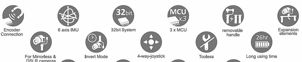
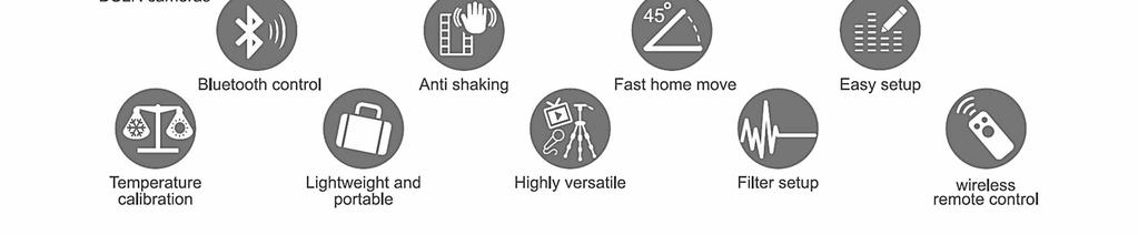
64 64
3-axes stabilized steady stative
 Instruction manual EN 3-axes stabilized steady stative for mirrorless cameras and digital single lens reflex cameras (SLRs) Pilotfly Technology Co. LTD. Jiafeng S. Rd. No.118,2F-2 Zhubei City, Hsinchu
3-Axis Stabilizing Gimbal For Smartphone
 3-Axis Stabilizing Gimbal For Smartphone Hohem Technology Co.,Ltd Safety instructions>> Read the operating instructions carefully and especially observe the safety information. If you do not follow the
HX1 Bluetooth Stereo Headset
 HX1 Bluetooth Stereo Headset Ref. nr.: 130.115 INSTRUCTION MANUAL V1.1 ENGLISH Congratulations to the purchase of this Max product. Please read this manual thoroughly prior to using the product in order
3-Axis Stabilized Handheld Gimbal
 3-Axis Stabilized Handheld Gimbal Guilin Feiyu Technology Incorporated Company User Manual EN V1.3 1. Product Overview * The showing sports camera is not included in the package Accessories Thumb Screw
20810 Sockeye Pl #200 Bend, OR Support and Sales Questions:
 20810 Sockeye Pl #200 Bend, OR 97701 Support and Sales Questions: Tel: (866) 977-6688 Monday to Friday 9AM to 5PM Pacific Time or email support@evogimbals.com EVOGimbals.com English Manual V2.0 CONTENTS
Aspera R7. User Manual
 1 Aspera R7 User Manual Contents Safety Information... 3 Appearance and Key Function... 5 Introduction... 6 Call Functions... 7 Notifications Bar... 8 Contacts... 9 Messaging... 9 Bluetooth and Wi-Fi...
USER MANUAL. For Flic. English
 USER MANUAL For Flic English Welcome to the Flic family! Take control and simplify your life with the push of a Flic. - Love, Flic Team Contents Setup guide 1 Pairing your Flic 2 Bluetooth connection 3
HOW TO USE THE SKY GLIDE - A GUIDE
 HOW TO USE THE SKY GLIDE - A GUIDE 1 Remove the stand from the box. Set on a flat surface. (In the version STR rack, turn the 5 elements). 2 Pull the unit SKY GLIDE and set it on a stand. 3 Turn the camera
RONIN THUMB CONTROLLER
 RONIN THUMB CONTROLLER User Manual V1.0 2015.6 Disclaimers and Warnings Congratulations on purchasing your new DJI product. Carefully read the manual and all disclaimers before using this product. By using
MX3 BT LED Party Tube
 MX3 BT LED Party Tube Ref. nr.: 130.121 INSTRUCTION MANUAL V1.1 ENGLISH Congratulations to the purchase of this Max product. Please read this manual thoroughly prior to using the product in order to benefit
3-Axis Stabilized Handheld Gimbal for Camera. Instructions. Guilin Feiyu Technology Incorporated Company
 3-Axis Stabilized Handheld Gimbal for Camera Instructions Guilin Feiyu Technology Incorporated Company User Manual E N V. 0 Catalogue. G6 Plus Overview 2. Quick Start Guide 3 3. Balance the Gimbal 4 Balance
Always there to help you. Register your product and get support at Question? Contact Philips AECS7000E.
 Always there to help you Register your product and get support at www.philips.com/welcome Question? Contact Philips AECS7000E User manual Contents 1 Important 2 Important safety information 2 Notice 2
Contents. Packing List. VILTA Mobile. Overview. Portable Bag. Quick Start. Charging Cable. Start Up. Lanyard. Specifications.
 www.freevisiontech.com Feel free to share your photos and videos with us and we might put them on our website. User Manual Facebook.com/FreevisionVILTA Twitter.com/FreeVisionVILTA instagram.com/freevision_vilta
3-Axis Stabilized Handheld Gimbal for Smartphone
 3-Axis Stabilized Handheld Gimbal for Smartphone Guilin Feiyu Technology Incorporated Company User Manual EN V 1.1 Product overview 1. Structure Smartphone shown in illustrations is for reference only
Reflow Kit V3 PRO Instruction Manual
 Reflow Kit V3 PRO www.beta-estore.com Beta LAYOUT Ltd. Bay 98 Shannon Free Zone, Co. Clare Ireland Telefon +353 (0) 61 70 11 70 Fax +353 (0) 61 70 11 65 Contents 1. V3 PRO Components...3 1.1 Reflow-Oven...
OSMO MOBILE 2. User Manual. v
 OSMO MOBILE 2 User Manual v1.0 2018.02 Searching for Keywords Search for keywords such as battery and install to find a topic. If you are using Adobe Acrobat Reader to read this document, press Ctrl+F
Ronin Release Notes. What s New?
 Date : 2017.07.12 IMU Firmware : V 3.1 GCU Firmware : V 1.4 DJI Assistant App ios : V 1.1.28 PC Assistant V 2.5 MAC Assistant V 2.5 User Manual V 2.0 GCU firmware v1.4, PC/Mac Assistant v2.5. Added support
3-Axis Stabilized Handheld Gimbal. Guilin Feiyu Technology Incorporated Company
 3-Axis Stabilized Handheld Gimbal Guilin Feiyu Technology Incorporated Company User Manual EN V1.0 1. Product Overview * The showing sports camera is not included in the package Thumb Screw Tilt Axis Cross
CX1 Outdoor Color-Changing Wireless Bluetooth Speaker Please fully charge the speaker prior to first use!
 CX1 Outdoor Color-Changing Wireless Bluetooth Speaker 130.109 Please fully charge the speaker prior to first use! 1 ENGLISH Congratulations to the purchase of this Max product. Please read this manual
3G WI-FI HOTSPOT USER MANUAL HHTSPT3GM42.
 3G WI-FI HOTSPOT USER MANUAL HHTSPT3GM42 www.hamletcom.com Dear Customer, thanks for choosing an Hamlet product. Please carefully follow the instructions for its use and maintenance and, once this item
Always there to help you. Register your product and get support at BT5580 BT5880. Question? Contact Philips.
 Always there to help you Register your product and get support at www.philips.com/support Question? Contact Philips BT5580 BT5880 User manual Contents 1 Important 2 2 Your Bluetooth speaker 3 Introduction
3-Axis Stabilized Handheld Gimbal. Guilin Feiyu Technology Incorporated Company
 3-Axis Stabilized Handheld Gimbal Guilin Feiyu Technology Incorporated Company User Manual EN V1.1 1. Product Overview * The showing sports camera is not included in the package Thumb Screw Tilt Axis Cross
To force your device to restart, press and hold the power button until your device vibrates.
 Quick Start CPN-W09 1 Your device at a glance Before you start, let's take a look at your new device. To power on your device, press and hold the power button until your device vibrates and the screen
Operating and Installation Manual. EASYLAB Expansion modules Type EM-TRF for 230 V AC mains voltage
 Operating and Installation Manual EASYLAB Expansion modules Type EM-TRF for 230 V AC mains voltage Type EM-TRF-USV for 230 V AC mains voltage; provides uninterruptible power supply (UPS) The art of handling
Always there to help you. Register your product and get support at DS3480. Question? Contact Philips.
 Always there to help you Register your product and get support at www.philips.com/welcome Question? Contact Philips DS3480 User manual Contents 1 Important 2 Safety 2 Notice 2 2 Your Docking Speaker 3
IMPORTANT MESSAGE BATTERY SAFETY! USER MANUAL English v1.2 WARRANTY LATEST INFORMATION
 IMPORTANT MESSAGE Thank you for choosing EVO Gimbals as your camera stabilization solution! We know that buying a new product can be very exciting and we are sure that you probably can not wait to use
3-Axis Stabilized Handheld Gimbal for Smartphone. Instructions. Guilin Feiyu Technology Incorporated Company. User Manual EN V1.0
 -Axis Stabilized Handheld Gimbal for Smartphone Instructions Guilin Feiyu Technology Incorporated Company User Manual EN V.0 Catalogue. SPG Overview. Quick Start Guide. Charging 5 4. Function operation
TG VR Gimbal User Manual V Accsoon. All Rights Reserved.
 TG20 360 VR Gimbal User Manual V1.0 20161209 www.accsoon.com E-mail: salse@accsoon.com 0 Disclaimers and Warnings Congratulations on purchasing you new VR Gimbal. Please read this manual and disclaimer
User Manual V K Camera with an Integrated 3-axis Gimbal
 User Manual V 1.1 4K Camera with an Integrated 3-axis Gimbal Table of Contents Introduction 3 At a Glance 3 Charging the Battery 4 Status Battery LED Indicator Description 4 Check the Battery Level 5 Insert
Honor Whistle Smart Control Rechargeable Headset User Guide
 Honor Whistle Smart Control Rechargeable Headset User Guide Box contents 1 x Headset 3 x Ear tips (small, medium and large) 1 x Ear hook Your headset at a glance 1 x USB adapter 1 x User guide 1 Charging
Helpline No. UK/Northern Ireland Rep. Ireland Web Support Model Number 82069
 Introduction 1 Congratulations on choosing to buy a Tevion product. By doing so you now have the assurance and peace of mind that comes with purchasing a product made by one of Europe s leading manufacturers.
Camera A14 and A34 Dome Camera
 Camera A14 and A34 Dome Camera Quick Start Guide Thank you for purchasing our product. If there are any questions, or requests, please do not hesitate to contact the dealer. About This Manual: This manual
Installation Manual. 65 Interactive LED/LCD. Model: HILF65101 (64.56 )
") Installation Manual 65 (64.56 ) Model: HILF65101 65 Interactive LED/LCD QUICK SETUP GUIDE For further information, see the user manual. Please contact directly if you have questions on the use of the touch
Installation Manual 65 (64.56 ) Model: HILF65101 65 Interactive LED/LCD QUICK SETUP GUIDE For further information, see the user manual. Please contact directly if you have questions on the use of the touch
Digital Night Vision Device Digital+ Series NV-440D3/NV-650D3/NV-760D3
 Digital Night Vision Device Digital+ Series NV-440D3/NV-650D3/NV-760D3 Instruction Manual Digital Night Vision Device Digital Series NV-440D3 / NV-650D3 / NV-760D3 Before using the device for the first
Reflow Kit V3 Basic Instruction Manual
 Reflow Kit V3 Basic Instruction Manual www.beta-estore.com Beta LAYOUT Ltd. Bay 98 Shannon Free Zone, Co. Clare Ireland Telefon +353 (0) 61 70 11 70 Fax +353 (0) 61 70 11 65 Contents 1. V3 Basic Components...
Startup Guide C01
 Startup Guide 4012988-00 C01 Startup Guide English Where to Find Information........................ 2 Safety Instructions.............................. 4 Important Safety Instructions...........................
Get set, go! Getting to know your go! stick USB modem. The package of your ACN go! stick contains the following items:
 Quick Start Guide Get set, go! Welcome to ACN Mobile Broadband. This guide details the simple steps to install your go! stick USB modem and connect to the Internet - you ll be up and running in no time!
ZYX User Manual V Revision
 ZYX User Manual V.00 206.07.26 Revision Contents Warning and Disclaimer... 3 I. Product Introduction... 4 II. Product List... 5. Package Contents... 5 III. Mounting & Configuration... 6. Gimbal Controller
CF3000 Dealer Diagnostic Tool Instruction Manual
 CF3000 Dealer Diagnostic Tool Instruction Manual Table of Contents: About the CF3000......3 Important Precautions......4 Components....5 Charging the CF3000......7 Licensing the CF3000.......8 Updating
To connect the AC adapter:
 Replacing the AC Adapter Replacing the AC Adapter 3 Plug the power cord into a wall outlet. The power indicator turns on. To connect the AC adapter: Connect the power cord to the AC adapter. Power indicator
WIRELESS POWERLINK USER MANUAL
 WIRELESS POWERLINK USER MANUAL Contents General... 3 Wireless Powerlink... 3 Package Contents... 4 Disposal of Old electrical Devices... 6 Installation... 7 Pairing Function... 7 Connecting the Devices...
Installation manual plugs and connectors with screw connection (16/32 A)
") EN Installation manual plugs and connectors with screw connection (16/32 60003213 Issue 04.2016 2016-04-01 Table of contents 1 About this manual 3 1.1 Structure of the warnings 3 1.2 Symbols used 4 1.3
EN Installation manual plugs and connectors with screw connection (16/32 60003213 Issue 04.2016 2016-04-01 Table of contents 1 About this manual 3 1.1 Structure of the warnings 3 1.2 Symbols used 4 1.3
Network Video Recorder Quick Start Guide
 Network Video Recorder Quick Start Guide Version 1.0.0 Table of Contents 1 Preparation Work... 1 2 HDD Installation... 2 2.1 SMART BOX... 2 2.2 SMART 1U... 2 2.3 MINI 1U, COMPACT 1U, 1U... 3 3 Rear Panel...
User Manual Revised 1-July-2015
 User Manual Revised 1-July-2015 LIMITED WARRANTY AND LIMITATION OF LIABILITY The use of the Auguscope is subject at all times to Augury's standard Management Platform Terms of Use, which can be viewed
DOWNLOADING THE APP FOR APPLE PHONES: DOWNLOADING THE APP FOR ANDROID PHONES: For Android Phones go to Google Play or the Android Store.
 DOWNLOADING THE APP FOR APPLE PHONES: DOWNLOADING THE APP FOR ANDROID PHONES: For Android Phones go to Google Play or the Android Store. For Apple Phones go to the app store and click GET. Make sure your
2 1.1 Safety using methods Definition of warning symbols Standard accessories Installation...
 Table of Contents 1 Satety precautions... 2 1.1 Safety using methods...2 1.2 Definition of warning symbols...2 2 Standard accessories......6 3 Installation... 7 3.2 Leg frame... 7 3.3 Installation and
Instruction Manual
 Waterproof Bluetooth USB Rechargeable Water Sport and Swimming Headphones PSWBT7 www.pyleaudio.com Instruction Manual READ THIS MANUAL CAREFULLY BEFORE USING THE BLUETOOTH HEADSET. Congratulations on purchasing
DEUTSCH ENGLISH NEDERLANDS FRANÇAIS NORSK ITALANIO ČEŠTINA Hersteller DAB650SI
 DEUTSCH NEDERLANDS NORSK ČEŠTINA ENGLISH FRANÇAIS ITALANIO Hersteller Wörlein GmbH Tel.: +49 9103/71670 Gewerbestrasse 12 Fax.: +49 9103/716712 D 90556 Cadolzburg Email. info@woerlein.com GERMANY Web:
MOBILE WIRELESS SSD FOR PHOTOGRAPHERS BY PHOTOGRAPHERS. Guide for MPortable
 MOBILE WIRELESS SSD FOR PHOTOGRAPHERS BY PHOTOGRAPHERS Guide for MPortable Contents 1 1.1 1.2 2. 2.1 2.2 2.3 3 3.1 3.2 4 5 5.1 5.2. 5.3 6 6.1 6.2 6.3 6.4 6.5 7 8 9 10 Overview What is the MPortable? Product
Always there to help you. Register your product and get support at BT5500. Question? Contact Philips.
 Always there to help you Register your product and get support at www.philips.com/support Question? Contact Philips BT5500 User manual Contents 1 Important 2 2 Your Bluetooth speaker 3 Introduction 3
BEAT 2.0 USER MANUAL
 BEAT 2.0 USER MANUAL FCC ID: 2ADLJBEAT20 The device complies with part 15 of the FCC Rules. Operation is subject to the following two conditions: (1) This device may not cause harmful interference, and
Achat 112 MA Achat 112 MA WH full-range speaker. user manual
 Achat 112 MA Achat 112 MA WH full-range speaker user manual Musikhaus Thomann Thomann GmbH Hans-Thomann-Straße 1 96138 Burgebrach Germany Telephone: +49 (0) 9546 9223-0 E-mail: info@thomann.de Internet:
BT6700. User manual. Register your product and get support at
 BT6700 User manual Register your product and get support at www.philips.com/support Contents 1 Important 1 Safety 1 Notice 1 2 Your Bluetooth speaker 2 Introduction 2 What's in the box 3 Overview of the
LED Commander 16/2 DMX controller. user manual
 LED Commander 16/2 DMX controller user manual Musikhaus Thomann Thomann GmbH Hans-Thomann-Strasse 1 96138 Burgebrach Germany Telephone: +49 (0) 9546 9223-0 E-mail: info@thomann.de Internet: www.thomann.de
Mk II 3DR MULTI-LINE LASER INSTRUCTION MANUAL
 Mk II 3DR MULTI-LINE LASER INSTRUCTION MANUAL SAFETY Read the following safety instructions before attempting to operate this product. Keep these instructions in a safe place or store in the carry case
OSMO MOBILE. User Manual V
 OSMO MOBILE User Manual V1.2 2017.03 Searching for Keywords Search for keywords such as battery and install to find a topic. If you are using Adobe Acrobat Reader to read this document, press Ctrl+F on
Reflow Kit V3 PRO Instruction Manual
 Reflow Kit V3 PRO www.beta-estore.com Beta LAYOUT Ltd. 765 Eubanks Drive Suite B1 Vacaville, CA 95688 USA Tel: +1 (707) 447 7744 Fax: +1 (707) 447 0896 Contents 1. V3 PRO Components... 3 1.1 Reflow-Oven...
Two-door Access Controller
 Two-door Access Controller Quick Start Guide V1.0.0 Preface Overview This document elaborates on structure, installation, interface and wiring of two-door access controller. Symbol Definition The following
Turn your smartphone into a smart laser measurer. The only app-driven device on the market USER S MANUAL
 Turn your smartphone into a smart laser measurer The only app-driven device on the market USER S MANUAL Safety Regulations Please read these safety regulations and operation guide carefully before operating.
License Plate Recognition (LPR) Camera Installation Manual
 Camera Installation Manual") License Plate Recognition (LPR) Camera Installation Manual 0 Hikvision LPR Camera Installation Manual About this Manual This Manual is applicable to Hikvision LPR Network Camera. This manual may contain
License Plate Recognition (LPR) Camera Installation Manual 0 Hikvision LPR Camera Installation Manual About this Manual This Manual is applicable to Hikvision LPR Network Camera. This manual may contain
...easy to operate with ProHomeIPC. IP Camera IC 600 Quick Start Guide
 ...easy to operate with ProHomeIPC IP Camera IC 600 Quick Start Guide Do you need detailed descriptions on how to use the app and operate the camera? Visit us at www.olympia-vertrieb.de Or scan this QR
3-axis Handheld Stabilizer Gimbal. Beholder DS2. Instruction Manual
 3-axis Handheld Stabilizer Gimbal Beholder DS2 Instruction Manual V1.0 2017.07 Before using the product, please read this manual carefully. Be sure to keep this book in a safe place so that you can check
THE BULLET. Bluetooth Speaker with NFC Technology. Instruction Manual
 Bluetooth Speaker with NFC Technology Instruction Manual Dear Customer, Thank you for purchasing an IRC product. We are pleased that you have chosen one of our products. At the same time, we are confident
CONTENT COMPONENTS OF PROJECTOR... 2 SPECIFICATION... 3 INSTRUCTION MANUAL... 3 CHARGING THE PROJECTOR... 3 SET UP... 4
 MP50M User Manual CONTENT COMPONENTS OF PROJECTOR... 2 SPECIFICATION... 3 INSTRUCTION MANUAL... 3 CHARGING THE PROJECTOR... 3 SET UP... 4 POWERING UP AND VIEWING MEDIA... 4 ADJUSTING VOLUME... 5 ADJUSTING
LDM M LASER DISTANCE MEASURER
 LDM120 120M LASER DISTANCE MEASURER INSTRUCTION MANUAL SAFETY Read the following safety instructions before attempting to operate this product. SAVE ALL WARNINGS AND INSTRUCTIONS FOR FUTURE REFERENCE.!
3-AXIS HANDHELD GIMBAL BATTERY SAFETY! WARRANTY LATEST INFORMATION
 I M PO R T A NT M E S S AGE 3-AXIS HANDHELD GIMBAL FOR MIRRORLESS CAMERAS Thank you for choosing EVO Gimbals as your camera stabilization solution! We know that buying a new product can be very exciting
Classic Flanger effects pedal. user manual
 Classic Flanger effects pedal user manual Musikhaus Thomann Thomann GmbH Hans-Thomann-Straße 1 96138 Burgebrach Germany Telephone: +49 (0) 9546 9223-0 E-mail: info@thomann.de Internet: www.thomann.de 31.07.2015,
Xemio-154 User Manual
 Xemio-154 User Manual User manual Sport MP3 Player with Micro SD Card of 4GB IMPORTANT: Read all instructions carefully before using this product. Retain this owner s manual for future reference. Cautions
Thank you for your purchase USER MANUAL
 Thank you for your purchase USER MANUAL MANUAL ICONS Warning: situations involving injury risk of the user or other persons. Attention: situations, when damage of device or other equipment may be caused.
User manual BT7900. Register your product and get support at
 User manual BT7900 Register your product and get support at www.philips.com/support Contents 1 Important 1 Safety 1 Notice 1 2 Your Bluetooth speaker 3 Introduction 3 What's in the box 3 Overview of the
Manual. Polaron SMPS Watt power supply for chargers. No. S2024. Copyright Graupner/SJ GmbH
 EN Manual Polaron SMPS 1500 1500 Watt power supply for chargers Copyright Graupner/SJ GmbH No. S2024 Index Introduction... 3 Service Centre... 3 Declaration of conformity... 3 Intended use... 4 Package
IMPORTANT MESSAGE 3 AXIS HANDHELD GIMBAL BATTERY SAFETY! USER MANUAL V1.2. Compatible With: WARRANTY LATEST INFORMATION
 IMPORTANT MESSAGE Thank you for choosing EVO Gimbals as your camera stabilization solution! We know that buying a new product can be very exciting and we are sure that you probably can not wait to use
TEL: / FAX:
 Self-leveling Rotary Laser FRE-211 Operating Manual P.R.Engineering Ltd UK www.laser-level.co.uk TEL: 01246 269 777 / FAX: 01246 260 007 SAFETY PRECAUTIONS: During instrument operation, be careful not
Multi Battery Charger MBC-08. Manual
 Multi Battery Charger MBC-08 Manual Imprint Information in this document is subject to change without notice. No part of this document may be reproduced or transmitted without the express written permission
Mobile Portable Terminal Quick Start Guide
 Mobile Portable Terminal Quick Start Guide Version 1.0.0 Table of Contents 1 Product Introduction... 1 1.1 Overview... 1 1.2 Packing List... 1 2 Structure and Installation... 2 2.1 Device Structure...
INSTRUCTION MANUAL CAT ecount
 Electron Microscopy Sciences INSTRUCTION MANUAL CAT. 70309-01 ecount Safety precautions The ecount is used specifically in bioscience, medical, and chemistry laboratories. It may come in contact with biohazardous
TA18 active subwoofer. user manual
 TA18 active subwoofer user manual Musikhaus Thomann e.k. Treppendorf 30 96138 Burgebrach Germany Telephone: +49 (0) 9546 9223-0 email: info@thomann.de Internet: www.thomann.de 30.11.2011 Table of contents
PowerPlant Tuner tuner pedal with power distribution. user manual
 PowerPlant Tuner tuner pedal with power distribution user manual Musikhaus Thomann Thomann GmbH Hans-Thomann-Straße 1 96138 Burgebrach Germany Telephone: +49 (0) 9546 9223-0 E-mail: info@thomann.de Internet:
Please read and retain these instructions for future reference v002: 14/03/17. Cradle, Charger, Instruction manual, Lithium-ion Battery 3.7 V d.c.
 Power Details: AC Charger Input voltage: 100-240V ~ 50/60Hz, 200mA Cradle Input Voltage: DC 5V, 500mA Cradle Output Voltage: DC 5V, 500mA Accessories: Cradle, Charger, Instruction manual, Lithium-ion Battery
LED Colour Flood 10W / 30W RGB LED floodlight. user manual
 LED Colour Flood 10W / 30W RGB LED floodlight user manual Musikhaus Thomann e.k. Treppendorf 30 96138 Burgebrach Germany Telephone: +49 (0) 9546 9223-0 E-mail: info@thomann.de Internet: www.thomann.de
Additional Camera Unit for Angelcare Monitors AC-CAM Compatible with models: AC517 - AC510 AC417 AC315 AC310
 OWNER S MANUAL Additional Camera Unit for Angelcare Monitors AC-CAM Compatible with models: AC517 - AC510 AC417 AC15 AC10 TABLE OF CONTENTS WARNINGS... SETUP REQUIREMENTS... Setting up the Camera... Instructions
TURBO HD TVI Bullet & Turret Camera
 TURBO HD TVI Bullet & Turret Camera User Manual UD03589B User Manual Thank you for purchasing our product. If there are any questions, or requests, do not hesitate to contact the dealer. This manual applies
LED Pixel Rail 40 RGB LED strip. user manual
 LED Pixel Rail 40 RGB LED strip user manual Musikhaus Thomann Thomann GmbH Hans-Thomann-Straße 1 96138 Burgebrach Germany Telephone: +49 (0) 9546 9223-0 E-mail: info@thomann.de Internet: www.thomann.de
Line reactors SINAMICS. SINAMICS G130 Line reactors. Safety information 1. General. Mechanical installation 3. Electrical installation
 Safety information 1 General 2 SINAMICS SINAMICS G130 Mechanical installation 3 Electrical installation 4 Technical specifications 5 Operating Instructions Control version V4.7 04/2014 A5E00331462A Legal
OWNER S MANUAL. Additional Camera Unit AC-CAM-210 Compatible with AC210 Baby Video Monitor TABLE OF CONTENTS
 OWNER S MANUAL Additional Camera Unit AC-CAM-210 Compatible with AC210 Baby Video Monitor TABLE OF CONTENTS WARNINGS...2 SETUP REQUIREMENTS... 3 Setting up the Camera... 4 Limited warranty...7 Technical
3-Axis Stabilized Handheld Gimbal for Camera. Instructions. Guilin Feiyu Technology Incorporated Company
 3-Axis Stabilized Handheld Gimbal for Camera Instructions Guilin Feiyu Technology Incorporated Company User Manual E N V2.0 Catalogue 1.Product Overview 1 2.Installation 2.1Battery Charging 2.2Battery
Aspera R25t User Manual
 Aspera R25t User Manual 1 Contents Safety Information... 3 Product Appearance, Buttons and Key Description... 6 Battery... 7 Power on and off... 8 Unlocking the Phone... 9 File Manager... 9 Phonebook and
Wireless Earbuds D32. User Manual
 Wireless Earbuds D32 User Manual Thank you for purchasing our products. This manual addresses the safety guidelines, warranty and operating instructions. Please review this manual thoroughly before operating
MOVEBAND Display Quick Start Guide
 MOVEBAND Display Quick Start Guide CJB1HD0LCAAA About the MOVEBAND Display MOVEBAND Display tracks your daily fitness activity and sleep data, allows you to set your own targets and then motivates you
...easy to operate with ProHomeIPC. IP-Kamera OC 800 Quick Start Guide
 ...easy to operate with ProHomeIPC IP-Kamera OC 800 Quick Start Guide Do you need detailed descriptions on how to use the app and operate the camera? Visit us at www.olympia-vertrieb.de Or scan this QR
Always there to help you. Register your product and get support at AEA1000. Question? Contact Philips.
 Always there to help you Register your product and get support at www.philips.com/welcome Question? Contact Philips AEA1000 User manual Contents 1 Important 2 Important safety information 2 Notice 3 English
650/1000 Fresnel 650/1000 PC 300/500 Antihalo 300/500 Fresnel theatre spotlight. user manual
 650/1000 Fresnel 650/1000 PC 300/500 Antihalo 300/500 Fresnel theatre spotlight user manual Musikhaus Thomann Thomann GmbH Hans-Thomann-Straße 1 96138 Burgebrach Germany Telephone: +49 (0) 9546 9223-0
Optional add-on cassette Attachment Instruction manual
 E6580774 Optional add-on cassette Attachment Instruction manual 1. INTRODUCTION 3 2. CONNECTION TO THE INVERTER 4 2.1 Fixing the option alone 4 2.2 Connection to the inverter 6 3. SPECIFICATION 8 4. WARRANTY
icore Kiosk system Installation Guide
 icore Kiosk system Installation Guide The reproduction, transmission or use of this document or its contents is not permitted without express authority. Offenders will be liable for damages. All rights,
Always there to help you. Register your product and get support at CVR600. Question? Contact Philips.
 Always there to help you Register your product and get support at www.philips.com/support Question? Contact Philips CVR600 User manual Contents 1 Safety 2 2 Your car driving recorder 3 Introduction 3
E8431 First Edition Model: T00CP
 Quick Start Guide E8431 First Edition Model: T00CP Copyright 2013 ASUSTeK COMPUTER INC. All Rights Reserved. No part of this manual, including the products and software described in it, may be reproduced,
Thanks for choosing 70mai dash cam. Product overview. Power key
 Thanks for choosing 70mai dash cam Equipped with a camera chip and image sensor which allows to record high-quality videos, 70mai dash cam becomes a perfect travel companion. Read this manual carefully
Always there to help you. Register your product and get support at BT3500. Question? Contact Philips.
 Always there to help you Register your product and get support at www.philips.com/support Question? Contact Philips BT3500 User manual Contents 1 Important 2 2 Your Bluetooth speaker 2 Introduction 2 What's
WayteQ GPS Navigation x880 User Manual. English Version
 WayteQ GPS Navigation x880 User Manual English Version Thanks for using WAYTEQ products! WAYTEQ reserves the rights of final interpretation of the manual. The product is subject to change without any further
Axiomet AXB Safety instructions
 Axiomet AXB350 1. Safety instructions Failure to follow the instructions listed below may result in electric shock or personal injury. Please read this manual carefully and thoroughly before using this