Introduction to ANSYS DesignModeler
|
|
|
- Morris Greene
- 6 years ago
- Views:
Transcription

1 Lecture 5 Modeling Release Introduction to ANSYS DesignModeler 2012 ANSYS, Inc. November 20, Release 14.5


2 Preprocessing Workflow Geometry Creation OR Geometry Import Geometry Operations Meshing Solver Sketches and Planes 3D Operations Meshing Methods 3D Operations Boolean, Body Operations, Split, etc Hybrid Mesh: Tet, Prisms, Pyramids Extrude, Revolve, Sweep, etc Geometry Import Options Direct CAD/Bi- Directional CAD Geometry Cleanup and Repair Automatic Cleanup Merge, Connect, Projection, Flow Volume Extraction, etc Hexa Dominant, Sweep meshing Assembly Meshing Global Mesh Settings Local Mesh Settings Sizing, Body/Sphere of Influence, Match Control, etc 2012 ANSYS, Inc. November 20, Release 14.5


3 Important DM Concepts: Body Types In DesignModeler, a body refers to a line, surface or solid Line body Has length and consists of point lower entities Surface body Has surface area and consists of point & line lower entities Solid body Has volume and consists of point, line & surface lower entities Bodies are listed in the Tree Outline identified by default names and icons Line body Surface body Solid body 2012 ANSYS, Inc. November 20, Release 14.5
4 Important DM Concepts: Body States Active & Frozen Bodies can exist in one of two states Active Frozen Active bodies merge automatically with bodies in contact or overlapping Frozen bodies remain independent Why use frozen bodies? Meshing; It is often more efficient to mesh a series of smaller topologically simpler bodies than one large complex shape Solver; Different physical models and boundary conditions can be applied to different areas of the model if they are defined as separate bodies 2012 ANSYS, Inc. November 20, Release 14.5
5 Important DM Concepts: Active Body State Working with Active Bodies Example; Two separate extrusions each creating an active body results in one body How to define a body as active? Before a body is created - choose Add Material After a body has been created as frozen - Use Unfreeze operation (available under Tools Menu) Displayed as Opaque Blue icon under Tree Outline 2012 ANSYS, Inc. November 20, Release 14.5


6 Important DM Concepts: Frozen Body State Working with Frozen Bodies Example; Two separate extrusions one of which is frozen results in two separate bodies How to define a body as frozen? Before a body is created - choose Add Frozen Slicing an active body will convert it to frozen Can be merged manually using Boolean operations or by converting to Active state using Unfreeze Displayed as Transparent Cyan icon under Tree Outline 2012 ANSYS, Inc. November 20, Release 14.5
7 3D Feature Creation Tools for creating new bodies or modifying existing bodies Used to create bodies Requires lower dimensioned geometry as base objects Results is a line/surface/solid body Applies blend/chamfer on edges/faces of existing bodies Used to modify existing bodies Results in modified or new bodies Quick creation of primitive shapes (without sketch) 2012 ANSYS, Inc. November 20, Release 14.5

8 Extrude Feature Extrude Details Geometry Can be a valid Sketch, selected face or Named Selection Operation Allows Add Material, Cut Material, Imprint Faces, Slice Material, Add frozen Discussed in detail in Next 3 Slides Direction Vector Automatically sets direction as normal when base object is set to sketch otherwise needs to be specified Plane axes, geometric edges and faces can be used to specify direction Preview of the operation Resultant body Sketch 2012 ANSYS, Inc. November 20, Release 14.5


9 Extrude Feature (cont ) Add Material Creates new body and unites with existing active bodies in contact or overlap Add Frozen: An independent body is created, with separate faces and edges Cut Material: Create holes or modify existing bodies by removing material Imprint Faces: Imprints the sketch on the faces of existing body Slice Material: Slice out resultant body from the existing Frozen body Sketch Add Material Add Frozen Cut Material Imprint faces Slice Material 2012 ANSYS, Inc. November 20, Release 14.5

10 Extrude Feature (cont ) Extrude Details Direction Normal Extrude Base object Normal to plane Reversed Extrude Base object in reverse direction of Normal Both-Symmetric Extrude symmetrically in both directions Both-Asymmetric Extrude asymmetrically in both directions 2012 ANSYS, Inc. November 20, Release 14.5
11 Extrude Feature (cont ) Extrude Details Extent Type : Fixed Extrude profile by specified distance Through All Extrude profile through entire model To Next Extrude profile up to first surface encountered Fixed Through All To Next 2012 ANSYS, Inc. November 20, Release 14.5

12 Extrude Feature (cont ) Extrude Details Extent Type cont To Faces Extrude profile up to one or more selected faces To Surfaces Extrude profile up to surface To Faces To Surfaces 2012 ANSYS, Inc. November 20, Release 14.5

13 Extrude Feature (cont ) Extrude Details Thin/Surface If enabled, a thin surface is extruded out of the base object with a default thickness of zero. Suitable for creating shell bodies Options to specify thickness 2012 ANSYS, Inc. November 20, Release 14.5


14 Extrude Feature (cont ) Extrude Details Merge Topology Yes: Optimizes the topology of feature bodies No: Leaves the topology of feature bodies unaltered Tips from a meshing Perspective: If the small faces are of interest during meshing, then set Merge Topology to NO If the small faces are unnecessarily forcing for fine mesh, then set Merge Topology to YES No Yes 2012 ANSYS, Inc. November 20, Release 14.5


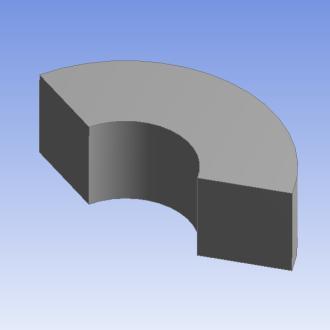
15 Revolve Feature Revolve Details Geometry is rotated to create a body of revolution Axis Specify Axis of Rotation for selected Base object (plane axis or edge) Angle Specify Rotation Angle Axis Base object 2012 ANSYS, Inc. November 20, Release 14.5


16 Sweep Feature Sweep Details Selected profile is swept along selected path to create bodies Profile : Specify the object to be swept Path : Specify the path for sweep Path Profile 2012 ANSYS, Inc. November 20, Release 14.5


17 Sweep Feature (cont ) Sweep Details Alignment : Specify orientation for profile with respect to swept path Path Tangent : Reorients the profile to keep its orientation consistent with respect to the path Global Axes : Profile orientation remains fixed irrespective of shape of the Path Path Tangent Global Axes 2012 ANSYS, Inc. November 20, Release 14.5


18 Sweep Feature (cont ) Sweep Details Scale Taper or expand the Profile as it is swept along the path of Sweep Twist Specification No Twist : Helical sweep is not created Turns : Specify number of turns to complete over the path length Pitch : Specify length per 1 full turn 4m 2012 ANSYS, Inc. November 20, Release 14.5


19 Skin/Loft Feature Skin/Loft Details Takes a series of profiles and creates a body fitting through them All profiles must have the same number of edges Multiple sketches 2012 ANSYS, Inc. November 20, Release 14.5
 Creation based on Selection Type;")


 Direction for")
 Inward Outward Midplane 2012 ANSYS,")
20 Thin/Surface Thin Surface Details Creates Thin Solid or Shell (Surface) Creation based on Selection Type; Faces to Keep/Faces to Remove/Bodies Only Faces to Keep: Selected faces used to form the thin solid or surface. Faces to Remove: Unselected faces used. Bodies Only: All faces used. Specification of zero thickness will create a surface body (can specify offset) Direction for generation of thickness can be inward, outward or both (midplane) Inward Outward Midplane 2012 ANSYS, Inc. November 20, Release 14.5


21 Fixed Radius Blend Fixed Radius Blend Details Creates a blend of specified radius on face/edges Face Selection Edge Selection 2012 ANSYS, Inc. November 20, Release 14.5


22 Pattern Function Creates copies of selected features Pattern Type: 3 options Linear, Circular or Rectangular Select Geometry (features or bodies) Specify Direction, Axis, Offset, Copies 2012 ANSYS, Inc. November 20, Release 14.5

23 Body Operation Body Manipulation Tools Contains eleven general body editing tools Options vary depending on whether the bodies are Active or Frozen Cut and imprint are not available when all bodies are Frozen Select Body Operation, set Type 2012 ANSYS, Inc. November 20, Release 14.5


24 Body Operation: Mirror Creates a mirror image body reflected in selected plane Select body or bodies Set Mirror Plane Original body deletion controlled by Preserve Bodies option Example Mirroring car body in the XY Plane preserving the original XY Plane 2012 ANSYS, Inc. November 20, Release 14.5


25 Body Operation: Move Moves and aligns selected bodies Select body or bodies Option to preserve bodies Set Source and Destination Planes Example Aligning two bodies using corresponding source and destination planes on each body respectively 2012 ANSYS, Inc. November 20, Release 14.5


26 Body Operation: Move, Align and Orient Using By Direction option, one can align bodies by using alignment vertices for aligning axes of bodies and orienting bodies with respect to each other. User needs to select bodies, pair vertices for Source & Destination Move and directions for Source & Destination Align and/or Source & Destination Orient 2012 ANSYS, Inc. November 20, Release 14.5


27 Body Operation: Scale Scale selected body or bodies Select body or bodies Set Scaling origin World Origin : Global coordinate origin Body Centroids: Centroid of the bodies selected Point: Selected Point Scale up : 2x 2012 ANSYS, Inc. November 20, Release 14.5


28 Body Operation: Translate, Rotate Translate the selected body in a specified direction Direction can be specified as coordinates or as a straight edge and distance Rotate selected bodies about a specified axis by a specified angle Axis can be specified as components or as a straight edge 2012 ANSYS, Inc. November 20, Release 14.5


29 Body Operation: Slice Material To Slice out one body from the another body 2012 ANSYS, Inc. November 20, Release 14.5


30 Boolean Unite, Subtract and Intersect Unite: Merges two or more bodies Subtract: Target Body subtract Tool Body Intersection: Union of All Intersections: Regions shared by two or more Tool Bodies Intersection of All Bodies: Regions shared by all Tool Bodies Tool Bodies Intersect all bodies Union of all intersections Union of all intersections preserving input bodies 2012 ANSYS, Inc. November 20, Release 14.5


31 Slice Operation under Create Slice Options Slice By Plane Model is sliced by selected plane Slice Off Faces Selected faces are sliced off and separate bodies are created from them Slice Off Edges Selected edges are sliced off and separate bodies are created from them Slice by Surface Selected surface is used as a slicing tool to slice Slice by Edge Loop Selected edge loop is used as a slicing tool Slice Off Faces 2012 ANSYS, Inc. November 20, Release 14.5


32 Slice Operation Post Share Topology Slice operation can now be used after Share Topology Helps to ensure proper connectivity while performing geometry decomposition Topologies remain shared after slice It is useful in walking around Limitations like use of Slice by Plane or Slice by Surface options before the Share Topology Method may merge the target body faces coinciding with the slicing sheet bodies or plane. Share Topology could be faster and more robust if decomposition is done after it 2012 ANSYS, Inc. November 20, Release 14.5
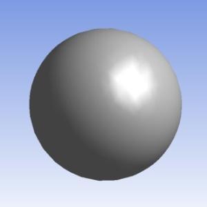
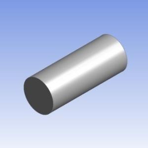
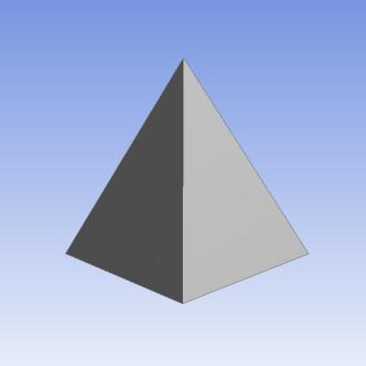
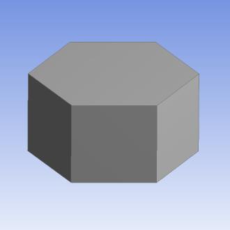
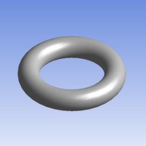
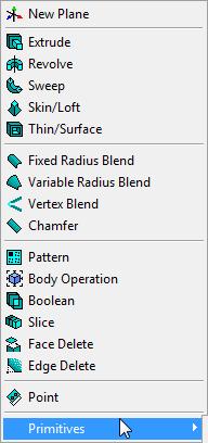
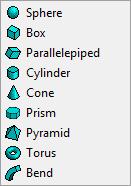
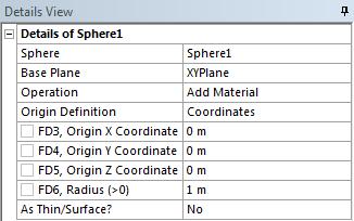
33 Primitive Geometries Used to create 3D primitives quickly 2012 ANSYS, Inc. November 20, Release 14.5
 require 2d models to be constructed on the XYPlane. Commonly used concept tools for creating surfaces...> Further concept tools detailed in separate lecture 2012 ANSYS, Inc.")
34 2D Feature Creation Concept Menu Tools for creating line & surface bodies 2d Surface Bodies can be created from existing edges, sketches or existing faces Some solvers (e.g Fluent, ANSYS 2D FEA) require 2d models to be constructed on the XYPlane. Commonly used concept tools for creating surfaces...> Further concept tools detailed in separate lecture 2012 ANSYS, Inc. November 20, Release 14.5

35 Surfaces From Sketches Used to create Surface bodies from existing sketches Can be used for 2D analysis Can be used for creating capping faces required for Fill operation 2012 ANSYS, Inc. November 20, Release 14.5

36 Surfaces From Faces Used to create Surface bodies from faces of existing models Can be used for 2D analysis 2012 ANSYS, Inc. November 20, Release 14.5

37 Surfaces From Edges Used to create Surface bodies from existing existing edges and Line bodies Can be used for 2D analysis Can be used for creating capping faces required for Fill operation Surface body created using 2 Line bodies and 2 edges 2012 ANSYS, Inc. November 20, Release 14.5

38 Suppression Suppressing Bodies Behaviour of Suppressed Body Will not be exported or transferred to other Workbench modules Not visible in Graphics view Identified by cross sign in Tree Outline How to Suppress or Unsuppress? Select the body to be suppressed, right click and select Suppress Body Select the body/bodies to be unsuppressed, right click and select Unsuppress Body option Suppressed 2012 ANSYS, Inc. November 20, Release 14.5

39 Visibility Hiding Geometry Behaviour of Hidden Bodies In Tree Outline, Hidden body is identified by transparent tick-mark sign Hidden bodies are transferred to other Workbench modules and can also be exported Useful when working with complex models How to Hide or Unhide? Select the body or face to hide, right click and select Hide Body Right click Show Body to restore view Suppressed 2012 ANSYS, Inc. November 20, Release 14.5


40 Named Selections What are Named Selections? Any number of entities of grouped under one name Can be created using one of two ways Select an entity or a group of entities, click RMB, select Named Selection from the context menu or Select an entity or a group of entities, click on Tools menu and select Named Selection In the details view, enter a name for the Named Selection or continue with the default name Click Generate Named selections can be assigned to points, lines, surfaces or solids 2012 ANSYS, Inc. November 20, Release 14.5

41 Uses for Named Selections Uses Group entities for reference Use as geometry for feature creation Cannot be solids Define parameters for parametric study Assign names to boundaries for simulation When used as boundary names, user must enable the transfer of named selection from DesignModeler to other Workbench modules (like Meshing, Fluent Solver etc.) For more information on boundary naming please see Appendix To enable the transfer of Named Selections, in the Workbench window, go to Tools Options Click on Geometry Import, enable the check box next to Named Selections. Empty the box under Filtering Prefixes if all named selections are to be transferred, otherwise only the named selections with the prefix in the textbox will be transferred 2012 ANSYS, Inc. November 20, Release 14.5


42 Named Selections : Propagation Property Original Selection Merge Yes No Split Copy Yes Selection propagates to all resultant entities No Selection propagates to just one of the resultant entities or destroyed 2012 ANSYS, Inc. November 20, Release 14.5

43 Single and Multi-Body Parts Working with Parts By default, DM places each body into one part by itself Single-body parts : Individual parts are meshed separately non-conformal mesh at interface Multi-body part : Two or more bodies in a single part Conformal mesh at interface Bodies can be grouped into a part in 2 ways : Select bodies. Click RMB and select Form New Part Select bodies. Go to Tools Form New Part Single-body Parts Multi-body Parts 2012 ANSYS, Inc. November 20, Release 14.5


44 Single and Multi-Body Parts Case 1: In DM: 1 part,1 body consisting of 1 solid Result of transferring this geometry to Meshing contains: 1 solid,1 body Entire solid meshed as one entity No internal faces DM DM Mesh 2012 ANSYS, Inc. November 20, Release 14.5


45 Single, Multi Solid Bodies Case 2: In DM: 3 parts, 3 bodies consisting of 3 solids Result of transferring this geometry to Meshing Contains : 3 solids, 3 bodies Each solid is meshed independently Nodes are not shared and do not line-up No connection between the 3 mesh regions for fluid flow and/or heat transfer Can connect using a Grid Interface in FLUENT/CFX DM Mesh DM Mesh 2012 ANSYS, Inc. November 20, Release 14.5


46 Single, Multi Solid Bodies Case 3: In DM: 1 multi-body part, 3 bodies/solids Result of transferring this geometry for Meshing contains:1 multi-body part, 3 bodies/solids Each solid meshed independently but node connectivity among solids is preserved Contains internal face which can be used for Post Processing DM Mesh DM Mesh 2012 ANSYS, Inc. November 20, Release 14.5
. This process creates Shared Topology resulting in changes to the geometry (example illustrated) and occurs automatically during the transfer.")

47 Share Topology Works on Multi-body parts only Common regions among Multi-body parts are not imprinted and connected until the geometry is transferred to a different application (Meshing, Mechanical etc. ). This process creates Shared Topology resulting in changes to the geometry (example illustrated) and occurs automatically during the transfer. To ensure that Named Selections contain the desired geometry (for use as boundaries) the Share Topology feature can be used manually in DesignModeler when the geometry is complete. Named Selections for boundaries should be created after this operation. DM DM Before Share Topology DM DM After Share Topology 2012 ANSYS, Inc. November 20, Release 14.5
48 Workshop 3 Modeling 2012 ANSYS, Inc. November 20, Release 14.5
49 Appendix Contents Extrude Merge Topology Example Variable Radius Blend Vertex Blend Chamfer Create Point Body Operation Cut Material Body Operation Imprint Body Operation Delete Named Selections for Boundaries in FLUENT 2012 ANSYS, Inc. November 20, Release 14.5

50 Extrude Feature: Example Merge Topology : Example Create a rectangular box by extruding one of side faces as shown in adjacent image In previous Extrude operation, if Merge Topology option is No, the rectangular box will be successfully created using sweep operation In previous Extrude operation, if Merge Topology option is Yes, the rectangular box cannot be created as there is no appropriate face for extrude No Yes 2012 ANSYS, Inc. November 20, Release 14.5


51 Variable Radius Blend Creates a blend of variable radius on face/edges The Details view is used to specify the start and end radius Specify Linear or Smooth Transition for Blend Linear Blend Smooth Blend 2012 ANSYS, Inc. November 20, Release 14.5
52 Vertex Blend Creates a blend on vertices Used to blend corners of Surface bodies The Details view is used to specify the Radius and Vertices 2012 ANSYS, Inc. November 20, Release 14.5


53 Chamfer Creates a chamfer on edge/faces The Details view is used to specify the left and right length or length and angle Left Right 2012 ANSYS, Inc. November 20, Release 14.5

54 Create: Point Used to create Construction Point, Point Load or Spot Weld Can choose definition types for creating Construction point : Single, Sequence by Delta, Sequence by N, From Coordinates File, Manual input Text file containing external point data in specific format can be imported through From Coordinates File option External Point Data Format 2012 ANSYS, Inc. November 20, Release 14.5


55 Body Operation: Cut Material This option is available when the model has any active bodies Uses the selected bodies to cut from other active bodies 2012 ANSYS, Inc. November 20, Release 14.5

56 Body Operation: Imprint This option is available when the model has any active bodies Uses the selected bodies to imprint on the active bodies 2012 ANSYS, Inc. November 20, Release 14.5
57 Body Operation: Delete Deletes the selected bodies Deleted bodies can be recovered by deleting or suppressing this Body Operation 2012 ANSYS, Inc. November 20, Release 14.5
58 Named Selections for Boundaries in Fluent Named selections can be assigned a name that corresponds to the desired boundary type Named selection Inletxx Outletxx Wallxx Pressure_inletxx (Other names not recognized as boundary type) Boundary Type Velocity Inlet Pressure Outlet Walls Pressure Inlet Walls xx in the names stand for any suffix Example: one can name a face to be assigned as boundary type of Velocity Inlet as inlet1 First letter of the names can be capital letters or small letters When such a model is transferred to Fluent, the Fluent solver will automatically recognize the boundary types from the names and assign the boundary type to these boundaries based on their assigned names, saving time for setup ANSYS, Inc. November 20, Release 14.5
Introduction to ANSYS DesignModeler
 Lecture 9 Beams and Shells 14. 5 Release Introduction to ANSYS DesignModeler 2012 ANSYS, Inc. November 20, 2012 1 Release 14.5 Beams & Shells The features in the Concept menu are used to create and modify
CATIA V5 Parametric Surface Modeling
 CATIA V5 Parametric Surface Modeling Version 5 Release 16 A- 1 Toolbars in A B A. Wireframe: Create 3D curves / lines/ points/ plane B. Surfaces: Create surfaces C. Operations: Join surfaces, Split & Trim
Chapter 6. Concept Modeling. ANSYS, Inc. Proprietary Inventory # May 11, ANSYS, Inc. All rights reserved.
 Chapter 6 Concept Modeling 6-1 Contents Concept Modeling Creating Line Bodies Modifying i Line Bodies Cross Sections Cross Section Alignment Cross Section Offset Surfaces From Lines Surfaces From Sketches
Lecture 7: Mesh Quality & Advanced Topics. Introduction to ANSYS Meshing Release ANSYS, Inc. February 12, 2015
 Lecture 7: Mesh Quality & Advanced Topics 15.0 Release Introduction to ANSYS Meshing 1 2015 ANSYS, Inc. February 12, 2015 Overview In this lecture we will learn: Impact of the Mesh Quality on the Solution
Advances in Pre-Processing
 Advances in Pre-Processing Laz Foley Confidence by Design Chicago June 14, 2012 1 Outline ANSYS DesignModeler Modeling Improvements ANSYS SpaceClaim Direct Modeler Workbench Integration and Model Preparation
Solid Modeling: Part 1
 Solid Modeling: Part 1 Basics of Revolving, Extruding, and Boolean Operations Revolving Exercise: Stepped Shaft Start AutoCAD and use the solid.dwt template file to create a new drawing. Create the top
Additional Exercises. You will perform the following exercises to practice the concepts learnt in this course:
 Additional Exercises You will perform the following exercises to practice the concepts learnt in this course: Master Exercise : Mobile Phone Plastic Bottle Exercise 1 Master Exercise : Mobile Phone In
Structural & Thermal Analysis Using the ANSYS Workbench Release 12.1 Environment
 ANSYS Workbench Tutorial Structural & Thermal Analysis Using the ANSYS Workbench Release 12.1 Environment Kent L. Lawrence Mechanical and Aerospace Engineering University of Texas at Arlington SDC PUBLICATIONS
3. Preprocessing of ABAQUS/CAE
 3.1 Create new model database 3. Preprocessing of ABAQUS/CAE A finite element analysis in ABAQUS/CAE starts from create new model database in the toolbar. Then save it with a name user defined. To build
3D Design with 123D Design
 3D Design with 123D Design Introduction: 3D Design involves thinking and creating in 3 dimensions. x, y and z axis Working with 123D Design 123D Design is a 3D design software package from Autodesk. A
Workshop 3: Cutcell Mesh Generation. Introduction to ANSYS Fluent Meshing Release. Release ANSYS, Inc.
 Workshop 3: Cutcell Mesh Generation 14.5 Release Introduction to ANSYS Fluent Meshing 1 2011 ANSYS, Inc. December 21, 2012 I Introduction Workshop Description: CutCell meshing is a general purpose meshing
CATIA Surface Design
 CATIA V5 Training Exercises CATIA Surface Design Version 5 Release 19 September 2008 EDU_CAT_EN_GS1_FX_V5R19 Table of Contents (1/2) Creating Wireframe Geometry: Recap Exercises 4 Creating Wireframe Geometry:
Introduction to ANSYS DesignModeler
 Lecture 7 CAD Connections 14. 5 Release Introduction to ANSYS DesignModeler 2012 ANSYS, Inc. November 20, 2012 1 Release 14.5 CAD Connections What will you learn from this presentation: Geometry Import
Create Complex Surfaces
 Create Complex Surfaces In this lesson, you will be introduced to the functionalities available in the Generative Surface Design workbench. Lesson content: Case Study: Surface Design Design Intent Stages
Solid Bodies and Disjointed Bodies
 Solid Bodies and Disjointed Bodies Generally speaking when modelling in Solid Works each Part file will contain single solid object. As you are modelling, each feature is merged or joined to the previous
Structural & Thermal Analysis using the ANSYS Workbench Release 11.0 Environment. Kent L. Lawrence
 ANSYS Workbench Tutorial Structural & Thermal Analysis using the ANSYS Workbench Release 11.0 Environment Kent L. Lawrence Mechanical and Aerospace Engineering University of Texas at Arlington SDC PUBLICATIONS
Complex Shapes Creation with Hybrid Modelling
 Complex Shapes Creation with Hybrid Modelling Peter De Strijker Technical Sales Executive MFG - Benelux Our Customer s Industries Discrete product manufacture Agenda Quality Analyses of sketches and surfaces
SOLIDWORKS 2016: A Power Guide for Beginners and Intermediate Users
 SOLIDWORKS 2016: A Power Guide for Beginners and Intermediate Users The premium provider of learning products and solutions www.cadartifex.com Table of Contents Dedication... 3 Preface... 15 Part 1. Introducing
Introduction to ANSYS
 Lecture 1 Introduction to ANSYS ICEM CFD 14. 0 Release Introduction to ANSYS ICEM CFD 1 2011 ANSYS, Inc. March 22, 2015 Purpose/Goals Ansys ICEM CFD is a general purpose grid generating program Grids for
Feature-Based Modeling and Optional Advanced Modeling. ENGR 1182 SolidWorks 05
 Feature-Based Modeling and Optional Advanced Modeling ENGR 1182 SolidWorks 05 Today s Objectives Feature-Based Modeling (comprised of 2 sections as shown below) 1. Breaking it down into features Creating
Geometry Definition in the ADINA User Interface (AUI) Daniel Jose Payen, Ph.D. March 7, 2016
 Daniel Jose Payen, Ph.D. March 7, 2016") Geometry Definition in the ADINA User Interface (AUI) Daniel Jose Payen, Ph.D. March 7, 2016 ADINA R&D, Inc., 2016 1 Topics Presented ADINA에서쓰이는 Geometry 종류 Simple (AUI) geometry ADINA-M geometry ADINA-M
Geometry Definition in the ADINA User Interface (AUI) Daniel Jose Payen, Ph.D. March 7, 2016 ADINA R&D, Inc., 2016 1 Topics Presented ADINA에서쓰이는 Geometry 종류 Simple (AUI) geometry ADINA-M geometry ADINA-M
Introduction to ANSYS ICEM CFD
 Lecture 1 Introduction to ANSYS ICEM CFD 14.5 Release Introduction to ANSYS ICEM CFD 2012 ANSYS, Inc. April 1, 2013 1 Release 14.5 Purpose/Goals Ansys ICEM CFD is a general purpose grid generating program
Convergent Modeling and Reverse Engineering
 Convergent Modeling and Reverse Engineering 25 October 2017 Realize innovation. Tod Parrella NX Design Product Management Product Engineering Solutions tod.parrella@siemens.com Realize innovation. Siemens
Introduction to ANSYS FLUENT Meshing
 Workshop 02 Volume Fill Methods Introduction to ANSYS FLUENT Meshing 1 2011 ANSYS, Inc. December 21, 2012 I Introduction Workshop Description: Mesh files will be read into the Fluent Meshing software ready
Autodesk Inventor 6 Essentials Instructor Guide Chapter Four: Creating Placed Features Chapter Outline This chapter provides instruction on the follow
 Chapter Four: Creating Placed Features Chapter Outline This chapter provides instruction on the following topics and provides exercises for students to practice their skills. Day Two Topic: How to create
Extrusion Revolve. ENGR 1182 SolidWorks 02
 Extrusion Revolve ENGR 1182 SolidWorks 02 Today s Objectives Creating 3D Shapes from 2D sketches using: Extrusion Revolve SW02 In-Class Activity Extrude a Camera Revolve a Wheel SW02 Out-of-Class Homework
Workbench Tutorial Flow Over an Airfoil, Page 1 ANSYS Workbench Tutorial Flow Over an Airfoil
 Workbench Tutorial Flow Over an Airfoil, Page 1 ANSYS Workbench Tutorial Flow Over an Airfoil Authors: Scott Richards, Keith Martin, and John M. Cimbala, Penn State University Latest revision: 17 January
Solidworks 2006 Surface-modeling
 Solidworks 2006 Surface-modeling (Tutorial 2-Mouse) Surface-modeling Solid-modeling A- 1 Assembly Design Design with a Master Model Surface-modeling Tutorial 2A Import 2D outline drawing into Solidworks2006
Introduction to ANSYS FLUENT Meshing
 Workshop 04 CAD Import and Meshing from Conformal Faceting Input 14.5 Release Introduction to ANSYS FLUENT Meshing 2011 ANSYS, Inc. December 21, 2012 1 I Introduction Workshop Description: CAD files will
Selective Space Structures Manual
 Selective Space Structures Manual February 2017 CONTENTS 1 Contents 1 Overview and Concept 4 1.1 General Concept........................... 4 1.2 Modules................................ 6 2 The 3S Generator
Lesson 4: Surface Re-limitation and Connection
 Lesson 4: Surface Re-limitation and Connection In this lesson you will learn how to limit the surfaces and form connection between the surfaces. Lesson contents: Case Study: Surface Re-limitation and Connection
Module 4A: Creating the 3D Model of Right and Oblique Pyramids
 Inventor (5) Module 4A: 4A- 1 Module 4A: Creating the 3D Model of Right and Oblique Pyramids In Module 4A, we will learn how to create 3D solid models of right-axis and oblique-axis pyramid (regular or
Lecture 2 Advanced Scripting of DesignModeler
 Lecture 2 Advanced Scripting of DesignModeler 1 Contents Supported API s of DesignModeler Attaching Debugger to DesignModeler Advanced scripting API s of DesignModeler Handlers Tree, Graphics, File, Event
Finite Element Analysis using ANSYS Mechanical APDL & ANSYS Workbench
 Finite Element Analysis using ANSYS Mechanical APDL & ANSYS Workbench Course Curriculum (Duration: 120 Hrs.) Section I: ANSYS Mechanical APDL Chapter 1: Before you start using ANSYS a. Introduction to
COMPUTER AIDED ARCHITECTURAL GRAPHICS FFD 201/Fall 2013 HAND OUT 1 : INTRODUCTION TO 3D
 COMPUTER AIDED ARCHITECTURAL GRAPHICS FFD 201/Fall 2013 INSTRUCTORS E-MAIL ADDRESS OFFICE HOURS Özgür Genca ozgurgenca@gmail.com part time Tuba Doğu tubadogu@gmail.com part time Şebnem Yanç Demirkan sebnem.demirkan@gmail.com
Appendix: To be performed during the lab session
 Appendix: To be performed during the lab session Flow over a Cylinder Two Dimensional Case Using ANSYS Workbench Simple Mesh Latest revision: September 18, 2014 The primary objective of this Tutorial is
Lesson 3: Surface Creation
 Lesson 3: Surface Creation In this lesson, you will learn how to create surfaces from wireframes. Lesson Contents: Case Study: Surface Creation Design Intent Stages in the Process Choice of Surface Sweeping
3D ModelingChapter1: Chapter. Objectives
 Chapter 1 3D ModelingChapter1: The lessons covered in this chapter familiarize you with 3D modeling and how you view your designs as you create them. You also learn the coordinate system and how you can
A Comprehensive Introduction to SolidWorks 2011
 A Comprehensive Introduction to SolidWorks 2011 Godfrey Onwubolu, Ph.D. SDC PUBLICATIONS www.sdcpublications.com Schroff Development Corporation Chapter 2 Geometric Construction Tools Objectives: When
Introduction to Solid Modeling Parametric Modeling. Mechanical Engineering Dept.
 Introduction to Solid Modeling Parametric Modeling 1 Why draw 3D Models? 3D models are easier to interpret. Simulation under real-life conditions. Less expensive than building a physical model. 3D models
Manipulating the Boundary Mesh
 Chapter 7. Manipulating the Boundary Mesh The first step in producing an unstructured grid is to define the shape of the domain boundaries. Using a preprocessor (GAMBIT or a third-party CAD package) you
ANSYS 14.0 Geometry and Meshing Update Steve Varnam ANSYS UK Ltd.
 ANSYS 14.0 Geometry and Meshing Update Steve Varnam ANSYS UK Ltd. 1 ANSYS Workbench Platform The most comprehensive platform for Multiphysics Simulations ANSYS Workbench Framework ANSYS DesignXplorer ANSYS
Solid Bodies and Disjointed bodies
 Solid Bodies and Disjointed bodies Generally speaking when modelling in Solid Works each Part file will contain single solid object. As you are modelling, each feature is merged or joined to the previous
ANSYS Workbench Guide
 ANSYS Workbench Guide Introduction This document serves as a step-by-step guide for conducting a Finite Element Analysis (FEA) using ANSYS Workbench. It will cover the use of the simulation package through
Geometric Modeling. Creating 3D solid geometry in a computer! Partial History of Geometric Modeling
 Geometric Modeling Creating 3D solid geometry in a computer! Partial History of Geometric Modeling 1963 Wireframe Computer Graphics Invented (Ivan Sutherland, MIT) 2 1 Partial History 1964 DAC-1, General
Module 1: Basics of Solids Modeling with SolidWorks
 Module 1: Basics of Solids Modeling with SolidWorks Introduction SolidWorks is the state of the art in computer-aided design (CAD). SolidWorks represents an object in a virtual environment just as it exists
SOLIDWORKS 2016 and Engineering Graphics
 SOLIDWORKS 2016 and Engineering Graphics An Integrated Approach Randy H. Shih SDC PUBLICATIONS Better Textbooks. Lower Prices. www.sdcpublications.com Powered by TCPDF (www.tcpdf.org) Visit the following
Parametric Modeling Design and Modeling 2011 Project Lead The Way, Inc.
 Parametric Modeling Design and Modeling 2011 Project Lead The Way, Inc. 3D Modeling Steps - Sketch Step 1 Sketch Geometry Sketch Geometry Line Sketch Tool 3D Modeling Steps - Constrain Step 1 Sketch Geometry
Introduction to ANSYS Fluent Meshing
 Workshop 06: Mesh Creation Including Removal of Gaps and Baffle Thickness 14.5 Release Introduction to ANSYS Fluent Meshing 1 2011 ANSYS, Inc. December 21, 2012 I Introduction Workshop Description: Fluent
Lecture 3 : General Preprocessing. Introduction to ANSYS Mechanical Release ANSYS, Inc. February 27, 2015
 Lecture 3 : General Preprocessing 16.0 Release Introduction to ANSYS Mechanical 1 2015 ANSYS, Inc. February 27, 2015 Chapter Overview In this chapter we cover basic preprocessing operations that are common
Autodesk Fusion 360: Model. Overview. Modeling techniques in Fusion 360
 Overview Modeling techniques in Fusion 360 Modeling in Fusion 360 is quite a different experience from how you would model in conventional history-based CAD software. Some users have expressed that it
Introduction to ANSYS ICEM CFD
 Lecture 4 Volume Meshing 14. 0 Release Introduction to ANSYS ICEM CFD 1 2011 ANSYS, Inc. March 21, 2012 Introduction to Volume Meshing To automatically create 3D elements to fill volumetric domain Generally
3D Modeling and Design Glossary - Beginner
 3D Modeling and Design Glossary - Beginner Align: to place or arrange (things) in a straight line. To use the Align tool, select at least two objects by Shift left-clicking on them or by dragging a box
Workbench Tutorial Minor Losses, Page 1 Tutorial Minor Losses using Pointwise and FLUENT
 Workbench Tutorial Minor Losses, Page 1 Tutorial Minor Losses using Pointwise and FLUENT Introduction This tutorial provides instructions for meshing two internal flows. Pointwise software will be used
equivalent stress to the yield stess.
 Example 10.2-1 [Ansys Workbench/Thermal Stress and User Defined Result] A 50m long deck sitting on superstructures that sit on top of substructures is modeled by a box shape of size 20 x 5 x 50 m 3. It
SOLIDWORKS Parametric Modeling with SDC. Covers material found on the CSWA exam. Randy H. Shih Paul J. Schilling
 Parametric Modeling with SOLIDWORKS 2015 Covers material found on the CSWA exam Randy H. Shih Paul J. Schilling SDC PUBLICATIONS Better Textbooks. Lower Prices. www.sdcpublications.com Powered by TCPDF
Education Curriculum Surface Design Specialist
 Education Curriculum Surface Design Specialist Invest your time in imagining next generation designs. Here s what we will teach you to give shape to your imagination. CATIA Surface Design Specialist CATIA
LAB # 2 3D Modeling, Properties Commands & Attributes
 COMSATS Institute of Information Technology Electrical Engineering Department (Islamabad Campus) LAB # 2 3D Modeling, Properties Commands & Attributes Designed by Syed Muzahir Abbas 1 1. Overview of the
L1 - Introduction. Contents. Introduction of CAD/CAM system Components of CAD/CAM systems Basic concepts of graphics programming
 L1 - Introduction Contents Introduction of CAD/CAM system Components of CAD/CAM systems Basic concepts of graphics programming 1 Definitions Computer-Aided Design (CAD) The technology concerned with the
SolidWorks 2013 and Engineering Graphics
 SolidWorks 2013 and Engineering Graphics An Integrated Approach Randy H. Shih SDC PUBLICATIONS Schroff Development Corporation Better Textbooks. Lower Prices. www.sdcpublications.com Visit the following
SOLIDWORKS 2019 Advanced Techniques
 SOLIDWORKS 2019 Advanced Techniques Mastering Parts, Surfaces, Sheet Metal, SimulationXpress, Top Down Assemblies, Core & Cavity Molds Paul Tran CSWE, CSWI SDC PUBLICATIONS Better Textbooks. Lower Prices.
TRAINING GUIDE SOLIDS-LESSON-3
 TRAINING GUIDE SOLIDS-LESSON-3 Mastercam Training Guide Objectives You will generate the solid model from the existing 2-dimensional geometry. This Lesson covers the following topics: Open an existing
3. MODELING A THREE-PIPE INTERSECTION (3-D)
") 3. MODELING A THREE-PIPE INTERSECTION (3-D) This tutorial employs primitives that is, predefined GAMBIT modeling components and procedures. There are two types of GAMBIT primitives: Geometry Mesh Geometry
3. MODELING A THREE-PIPE INTERSECTION (3-D) This tutorial employs primitives that is, predefined GAMBIT modeling components and procedures. There are two types of GAMBIT primitives: Geometry Mesh Geometry
Automatic & Robust Meshing in Fluids 2011 ANSYS Regional Conferences
 Automatic & Robust Meshing in Fluids 2011 ANSYS Regional Conferences 1 This is just a taste Note that full 14.0 update webinars of an hour per product will be scheduled closer to the release This presentation
Introduction to ANSYS Meshing. Workshop plan
 Lecture 2 Introduction to ANSYS Meshing 2014 W2-1 Schedule WEiP Workshop plan Week 1 - Quick start in ANSYS Week 2 Geometry DesignModeler (DM) Week 3 Mesh Meshing Week 4 Solver FLUENT/CFX Week 5 - Post
Parametric Modeling with SolidWorks
 Parametric Modeling with SolidWorks 2012 LEGO MINDSTORMS NXT Assembly Project Included Randy H. Shih Paul J. Schilling SDC PUBLICATIONS Schroff Development Corporation Better Textbooks. Lower Prices. www.sdcpublications.com
Parametric Modeling with SOLIDWORKS 2017
 Parametric Modeling with SOLIDWORKS 2017 NEW Contains a new chapter on 3D printing Covers material found on the CSWA exam Randy H. Shih Paul J. Schilling SDC PUBLICATIONS Better Textbooks. Lower Prices.
Surfacing using Creo Parametric 3.0
 Surfacing using Creo Parametric 3.0 Overview Course Code Course Length TRN-4506-T 3 Days In this course, you will learn how to use various techniques to create complex surfaces with tangent and curvature
Autodesk Fusion 360 Training: The Future of Making Things Attendee Guide
 Autodesk Fusion 360 Training: The Future of Making Things Attendee Guide Abstract After completing this workshop, you will have a basic understanding of editing 3D models using Autodesk Fusion 360 TM to
Images from 3D Creative Magazine. 3D Modelling Systems
 Images from 3D Creative Magazine 3D Modelling Systems Contents Reference & Accuracy 3D Primitives Transforms Move (Translate) Rotate Scale Mirror Align 3D Booleans Deforms Bend Taper Skew Twist Squash
Best Practices: Volume Meshing Kynan Maley
 Best Practices: Volume Meshing Kynan Maley Volume Meshing Volume meshing is the basic tool that allows the creation of the space discretization needed to solve most of the CAE equations for: CFD Stress
Geometric Modeling. Introduction
 Geometric Modeling Introduction Geometric modeling is as important to CAD as governing equilibrium equations to classical engineering fields as mechanics and thermal fluids. intelligent decision on the
Workshop 1: Basic Skills
 Workshop 1: Basic Skills 14.5 Release Introduction to ANSYS Fluent Meshing 2011 ANSYS, Inc. December 21, 2012 1 I Introduction Workshop Description: This workshop shows some of the clean up tools in Tgrid
Input CAD Solid Model Assemblies - Split into separate Part Files. DXF, IGES WMF, EMF STL, VDA, Rhino Parasolid, ACIS
 General NC File Output List NC Code Post Processor Selection Printer/Plotter Output Insert Existing Drawing File Input NC Code as Geometry or Tool Paths Input Raster Image Files Report Creator and Designer
Engineering Drawing II
 Instructional Unit Basic Shading and Rendering -Basic Shading -Students will be able -Demonstrate the ability Class Discussions 3.1.12.B, -Basic Rendering to shade a 3D model to apply shading to a 3D 3.2.12.C,
Advanced CAD Modelling Course (SolidWorks 2009)
") Advanced CAD Modelling Course (SolidWorks 2009) Published by: The National Centre for Technology in Education And T4 Technology Subjects Support Service National Centre for Technology in Education Dublin
Advanced CAD Modelling Course (SolidWorks 2009) Published by: The National Centre for Technology in Education And T4 Technology Subjects Support Service National Centre for Technology in Education Dublin
Introduction And Overview ANSYS, Inc. All rights reserved. 1 ANSYS, Inc. Proprietary
 Introduction And Overview 2006 ANSYS, Inc. All rights reserved. 1 ANSYS, Inc. Proprietary The ANSYS Workbench represents more than a general purpose engineering tool. It provides a highly integrated engineering
Technical Education Services
 Autodesk Fusion 360: Introduction to Parametric Modeling Course Length: 3 days Official Training Guide The Autodesk Fusion 360 Introduction to Parametric Modeling training course provides you with an understanding
Chapter 9 3D Modeling
 Chapter 9 3D Modeling Copyright The McGraw-Hill Companies, Inc. Permission required for reproduction or display. 3D Modeling Snapshot Since Mid 1980 s become common place in industry Software Types Wireframe
AutoCAD 2013 Tutorial - Second Level: 3D Modeling
 AutoCAD 2013 Tutorial - Second Level: 3D Modeling Randy H. Shih SDC PUBLICATIONS Schroff Development Corporation Better Textbooks. Lower Prices. www.sdcpublications.com Visit the following websites to
VERO UK TRAINING MATERIAL
 VERO UK TRAINING MATERIAL VISI Basic 2-D Modelling course (V-16) VISI Modelling 2D Design Introduction Many component designs follow a similar route, beginning with a 2D design, part modelled using solids
Learning. Modeling, Assembly and Analysis SOLIDWORKS Randy H. Shih SDC. Better Textbooks. Lower Prices.
 Learning SOLIDWORKS 2016 Modeling, Assembly and Analysis Randy H. Shih SDC PUBLICATIONS Better Textbooks. Lower Prices. www.sdcpublications.com Powered by TCPDF (www.tcpdf.org) Visit the following websites
Autodesk 123D Beta5 Overview
 Autodesk 123D Beta5 Overview Welcome. This overview document for Autodesk 123D will assist you in developing your understanding of the software and how you can use it to create your design ideas. Designing
Mechanical Design V5R19 Update
 CATIA V5 Training Foils Mechanical Design V5R19 Update Version 5 Release 19 August 2008 EDU_CAT_EN_MD2_UF_V5R19 1 About this course Objectives of the course Upon completion of this course you will be able
Page 1 of 7. Please contact you netfabb distributor for more information and ordering.
 Page 1 of 7 New Features in netfabb Professional 5 Overview based on netfabb Professional 5.1 including most important features from previous netfabb versions Usability improvements Automatic Repair one-click
QUICK-START TUTORIALS
 PUERMC02_0132276593.QXD 08/09/2006 06:05 PM Page 83 QUICK-START TUTORIALS Chapter Objectives Create two real 3D modeling projects, starting them from scratch. Know the difference between representing 3D
Design Intent of Geometric Models
 School of Computer Science Cardiff University Design Intent of Geometric Models Frank C. Langbein GR/M78267 GR/S69085/01 NUF-NAL 00638/G Massey University 22nd September 2004; Version 1.0 Design Intent
SolidWorks 2013 Part II - Advanced Techniques
 SolidWorks 2013 Part II - Advanced Techniques Parts, Surfaces, Sheet Metal, SimulationXpress, Top-Down Assemblies, Core and Cavity Molds Paul Tran CSWE, CSWI Supplemental Files SDC PUBLICATIONS Schroff
MAE 455 COMPUTER-AIDED DESIGN AND DRAFTING MIDTERM EXAM PRACTICE QUESTIONS. Name: You are allowed one sheet of notes.
 47 MAE 455 COMPUTER-AIDED DESIGN AND DRAFTING MIDTERM EXAM PRACTICE QUESTIONS Name: You are allowed one sheet of notes. 1. What constraints could be added to fully constrain the wireframe shown? Include
Licom Systems Ltd., Training Course Notes. 3D Surface Creation
 , Training Course Notes Work Volume and Work Planes...........................1 Overview..........................................1 Work Volume....................................1 Work Plane......................................1
SimLab Release Notes. 1 A l t a i r E n g i n e e r i n g
 SimLab 11.0 Release Notes 1 A l t a i r E n g i n e e r i n g System Support extended to load and save GDA/SLB files of size greater than 4GB. Memory allocation is enhanced to support large models. Kubrix
Tutorial Second Level
 AutoCAD 2018 Tutorial Second Level 3D Modeling Randy H. Shih SDC PUBLICATIONS Better Textbooks. Lower Prices. www.sdcpublications.com Powered by TCPDF (www.tcpdf.org) Visit the following websites to learn
Equipment Support Structures
 Equipment Support Structures Overview Conventions What's New? Getting Started Setting Up Your Session Creating a Simple Structural Frame Creating Non-uniform Columns Creating Plates with Openings Bracing
3 Polygonal Modeling. Getting Started with Maya 103
 3 Polygonal Modeling In Maya, modeling refers to the process of creating virtual 3D surfaces for the characters and objects in the Maya scene. Surfaces play an important role in the overall Maya workflow
Femap v11.2 Geometry Updates
 Femap v11.2 Geometry Updates Chip Fricke, Femap Principal Applications Engineer chip.fricke@siemens.com Femap Symposium Series 2015 June, 2015 Femap Symposium Series 2015 Femap v11.2 Geometry Creation
Chapter 2 Parametric Modeling Fundamentals
 2-1 Chapter 2 Parametric Modeling Fundamentals Create Simple Extruded Solid Models Understand the Basic Parametric Modeling Procedure Create 2-D Sketches Understand the Shape before Size Approach Use the
Equipment Support Structures
 Page 1 Equipment Support Structures Preface Using This Guide Where to Find More Information Conventions What's New? Getting Started Setting Up Your Session Creating a Simple Structural Frame Creating Non-uniform
Implementation in COMSOL
 Implementation in COMSOL The transient Navier-Stoke equation will be solved in COMSOL. A text (.txt) file needs to be created that contains the velocity at the inlet of the common carotid (calculated as
ANSYS FLUENT. Lecture 3. Basic Overview of Using the FLUENT User Interface L3-1. Customer Training Material
 Lecture 3 Basic Overview of Using the FLUENT User Interface Introduction to ANSYS FLUENT L3-1 Parallel Processing FLUENT can readily be run across many processors in parallel. This will greatly speed up
Viscous Hybrid Mesh Generation
 Tutorial 4. Viscous Hybrid Mesh Generation Introduction In cases where you want to resolve the boundary layer, it is often more efficient to use prismatic cells in the boundary layer rather than tetrahedral