Noise and Artifacts in FMRI
|
|
|
- Mervyn Barrett
- 6 years ago
- Views:
Transcription
1 Noise and Artifacts in FMRI Instructor: Luis Hernandez-Garcia, Ph.D. Associate Research Professor FMRI Laboratory, Biomedical Engineering
2 FMRI analysis - synopsis of what you ll do next week 1. Formulate a model of activation. 2. Examine the time-series at every voxel : Fit your model to the data. 1. Does it fit? 2. What s the amplitude? 3. Make some statistical images 3. Compare statistical images between subjects, groups.
3 Typical data arrangement One 3D image per time point Most popular: AVW or Analyze format: header information (.hdr) the image itself (.img) Useful to read all the data as a matrix Rows = time Columns = space (collapsed to 1 dimension) ( or vice versa)
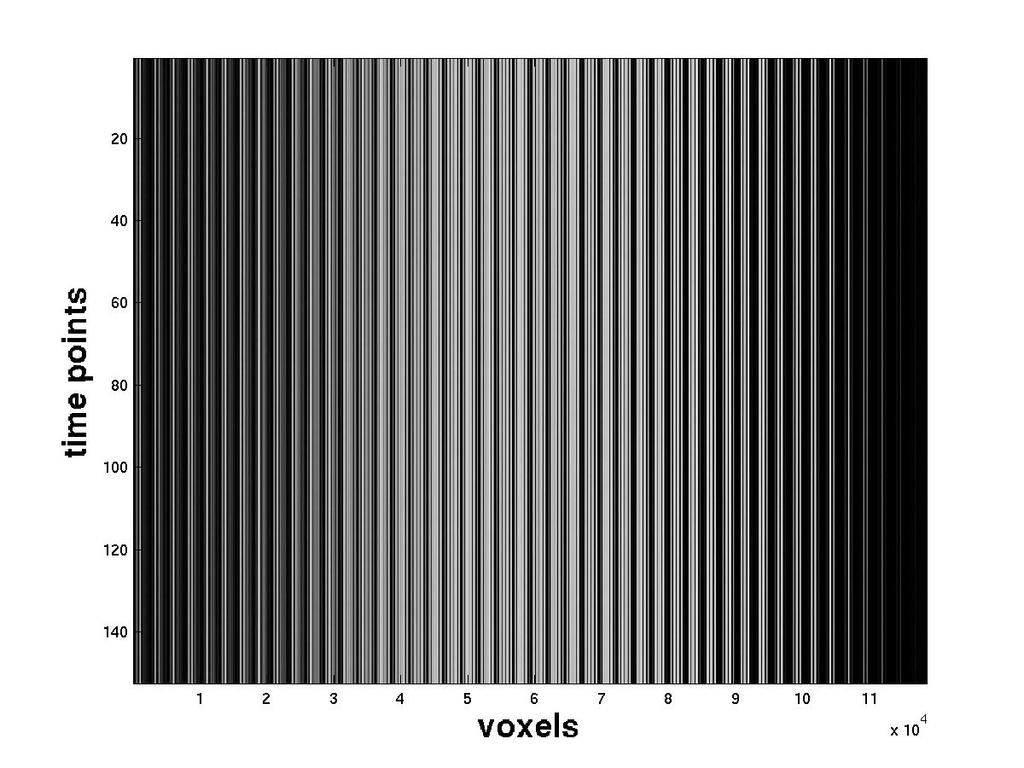
4 Example
5 Implicit Assumptions in Analysis Each Voxel contains a time series from that voxel ONLY All voxels in a given 3D image are sampled at the same time All brains are morphologically identical Paradigm is the SOLE SOURCE of variance in the time series. The image corresponds Exactly to the to the anatomy
6 The harsh reality Scanner spiking issues T1 settling time Global signal (mean over space): a good indicator of large scale changes in signal Courtesy of Derek Nee (Plot was made using spm_global.m) Interpolation from Slice timing correction spreads artifacts over time!
7 Lecture Goals Understand the following confounds in fmri and what corrections exist Slice Timing effects (temporal shifting) Movement (rigid body realignment) Physiological Artifacts: respiration and heart beat (regression filters) Electronic Noise (filters and autoregressive models) Morphology (non-linear warping) Image distortions ( susceptibility, ghosting, off-resonance)
8 Lecture Goals (II) As a side effect, you will be introduced to signal and image processing concepts: 1. Linear transformations 2. Sampling, re-sampling, interpolation 3. Optimization, cost functions 4. other side effects include drowsiness, nausea
9 Lecture Goals Understand the following confounds in fmri and what corrections exist Slice Timing effects (temporal shifting) Movement (rigid body realignment) Physiological Artifacts: respiration and heart beat (regression filters) Image distortions ( susceptibility, ghosting) Electronic Noise (filters and autoregressive models) Morphology (non-linear warping)
10 Timing Errors MR images are typically collected one slice at a time (exceptions: 3D imaging, multi-band imaging) The slices can be collected sequentially or interleaved. This is also true in Multi-band imaging. Delay between slice excitations is typically = TR / (num. slices) Therefore, the time series are time-shifted differently in each slice
11 FMRI data layout TR 2TR 3TR slice 1 slice 4 time
12 Acquisition TR 2TR 3TR slice 1 slice 4 time
13 Acquisition TR 2TR 3TR slice 1 slice 4 time
14 Sampling Error in Time The data you think you have The data you really have
15 Sampling Error in Time How the data looks The true data so shift it back!
16 Interpolation / Temporal shifting Time shift is the same as interpolation Interpolation: calculate a missing data point from its neighbors Interpolation = weighted average slice 1 slice 4 TR 2TR 3TR time
17 Interpolation = Temporal shift by a fraction of a sample Have: Time domain Frequency Domain f( t ) F(w) Want: f( t - t ) e -iwt F(w)
18 Temporal shifting strategy 1. Fourier transform along time dimension 2. Add linear phase increment (multiply the complex data by e -ifw ) 3. Inverse fourier transform 4. Note: this strategy uses the whole time series. Noise in one sample can contaminate the whole time course!
19 Interpolation side effects Scanner spiking issues T1 settling time Subject movement Global signal (mean over space): a good indicator of large scale changes in signal Interpolation from Slice timing correction spreads artifacts over time! Courtesy of Derek Nee
20 Local interpolation (use a few neighbors at a time) Multiplication in frequency = Convolution in time Instead of the Frequency domain phase shift, calculate a weighted average of a few neighbors neighbors Weights are determined by the sinc() function Prevents local errors from affecting the whole time series Can be faster Can build filters onto the sinc function. Drawbacks: ringing artifacts if not enough points are used, Too slow if too many points are used in window.
21 Does it matter how we interpolate? Alternatives to the sinc() function: Nearest Neighbor Linear, Bilinear, Trilinear Polynomial They can all be shown to be some sort of weighted average : a convolution with a different kernel different properties They are all approximations based on some assumptions about the function. Sinc is most accurate as long as enough data are used. These concepts also apply to image interpolation, resampling, etc.
22 Lecture Goals Understand the following confounds in fmri and what corrections exist Slice Timing effects (temporal shifting) Movement (rigid body realignment) Physiological Artifacts: respiration and heart beat (regression filters) Image distortions ( susceptibility, ghosting) Electronic Noise (filters and autoregressive models) Morphology (non-linear warping)
23 Movie: Uncorrected movement

24 Movie: Corrected Movement
25 Movement
26 Movement
27 Movement Interpolate this point from its neighbors
28 Resampling the image Think of realignment as transforming the sampling grid, rather than the image. Interpolation: Choose weighting function (kernel): Nearest neighbor bi-linear, tri-linear interpolation sinc interpolation
29 Movement: figuring out the new coordinates In 2 Dimensions: shift from (x 1,y 1 ) to (x 2,y 2 ): x 2 = x 1 + Dx y 2 = y 1 + Dy (x 1, y 1 ) (x 2, y 2 ) Rotation from (x 1, y 1 ) to (x 2,y 2 ): x 2 = x 1 cos(q) + y 1 sin(q) y 2 = -x 1 sin(q) + y 1 cos(q) (x 2, y 2 ) q (x 1, y 1 )
30 2-D Transformation matrix Both Together (note that the order matters) x 2 = x 1 cos(q) + y 1 sin(q) + Dx y 2 = -x 1 sin(q) + y 1 cos(q) + Dy or In Matrix Form x 2 cos(q) sin(q) Dx x 1 y 2 = -sin(q) cos(q) Dy y
31 2-D Transformation matrix (x 2,y 2 ) = A(x 1, y 1 ) this extends to N-dimensions too
32 3-D Rotation matrices cos(q) sin(q) 0 0 -sin(q) cos(q) cos(q) 0 sin(q) sin(q) 0 cos(q) cos(q) 1 sin(q) 0 -sin(q) 0 cos(q) xy plane rotation xz plane rotation yz plane rotation
33 Estimation of Movement 1. Choose a set of translations, rotations 2. Combine the six transformations matrices (linear operators) into one rigid body transformation r 2 = A r 1 3. Resample the images at the new locations 4. Are the two images more alike? 5. Repeat and search for the best matrix A
34 Comparing images: cost function How do you know two images match? 1. Least squares difference S ( I 1 - I 2 ) 2 2. Normalized correlation, correlation ratio S(I 1 I 2 ) Var(E[I 1 I 2 ]) (Var(I 1 ) (Var( I 2 ) ) 1/2 Var(I 2 ) 3. Mutual information 4. others.m. Jenkinson and S.M. Smith. Medical Image Analysis, 5(2): , June 2001 " p(i M(I 1,I 2 ) = p(i 1,I 2 )log 1,I 2 ) % 2 $ ' # p(i 1 )p(i 2 )& i, j
35 Search Strategies Least squares (Y=Xb)? Steepest descent: vary parameters and compute the gradient in the cost function (error). Keep going as long as it gets better. There are variations on this theme: simplex Newton s method / gradient descent Adaptive methods others

36 Sample Movement Parameters
37 Movement Noise In addition to misplacing voxels, you introduce a fluctuation in signal intensity during realignment This is a complicated function of the movement: Movement affects the k-space trajectory Mixes partial volumes, Therefore: Interpolation methods also have an effect on intensity.
38 Movement Noise corrections Minimize movement while acquiring data whenever possible!! Including movement regressors as confounds Reduces residual variance. Complicated function, but the signal fluctuation is well correlated with the movement parameters. Higher order motion models (Lund et al., 2005 NeuroImage) are extremely helpful If movement is correlated with task = BIG TROUBLE!
39 Movement Artefacts
40 Lecture Goals Understand the following confounds in fmri and what corrections exist Slice Timing effects (temporal shifting) Movement (rigid body realignment) Physiological Artifacts: respiration and heart beat (regression filters) Image distortions ( susceptibility, ghosting) Electronic Noise (filters and autoregressive models) Morphology (non-linear warping)
41 Physiological oscillations Time domain frequency domain courtesy of Douglas Noll


42 Cardiac and Respiratory Variance anatomy Residual Variance w/o Physio correction Residual Variance w/ Physio correction Data courtesy of Scott Peltier
43 Cardiac Noise Blood flow is pulsatile -> changes blood volume, and velocity. How blood flow affects the MR signal: Flow enhancement (incoming spins have not received any RF, fully relaxed -> more signal) Flow void (sometimes spins flow so fast through the plane that they don t see the RF pulse, or they flow out before they can be encoded -> less signal ) Flow induced displacement (additional phase acquired because of in-plane movement -> distorted/displaced signal, ghosting)
44 Reduction of cardiac effects during Acquisition Use a smaller flip angle - reduces flow enhancements and voids. Use flow spoilers to remove vascular signals. (pair of symmetric gradient pulses, a.k.a. crushers, makes moving spins get out of phase with each other.) Use fast acquisition (single shot) to reduce ghosting. Cardiac Gating
45 Reduction of cardiac artifacts Digital Filters after acquisition Measure cardiac waveform and include in analysis as a confound. Note: watch out for aliasing!! heartbeat > 1 Hz typical Nyquist frequency < 0.5 Hz This is an area where SMS is helpful.
46 Respiration Air and Tissue difference in magnetic susceptibility ( c ) : Distortion of B 0 field Chest movement changes the shape of the B 0 field. Changes gradients too. Resonant frequency changes slightly ( Recall that w 0 = gb 0 ) Blood Pressure and CBF change slightly with respiration pulsation of arteries -> CBV pco2 -> CBF
47 Corrections for Respiration Fast image acquisition (single shot) Record Respiratory waveform and use as a confound. (Note- sometimes it s correlated with task of interest) Notch or band-stop Filters Aliasing is not as much of a problem as in cardiac fluctuations, but might still interfere with design Respiration ~ 0.08 Hz BOLD ~ from 0.01 to 0.05 (broad) typical Nyquist frequency < 0.5 Hz
48 Lecture Goals Understand the following confounds in fmri and what corrections exist Slice Timing effects (temporal shifting) Movement (rigid body realignment) Physiological Artifacts: respiration and heart beat (regression filters) Image distortions ( susceptibility, ghosting) Electronic Noise (filters and autoregressive models) Morphology (non-linear warping)
49 Signal Intensity in MRI The signal is proportional to M and V, where: V = Dx Dy Dz is the voxel volume M is the intensity of the magnetization vector. Proton Density and B0 determine the size of the spin populations, I.e. - magnitude of M Acquisition timing also affects the observed Signal ρ(1 e TR /T1 )e TE /T 2
50 Definitions Signal to Noise Ratio( SNR) : Ratio of the amount of Signal to the standard deviation of the noise Contrast to Noise Ratio (CNR): Ratio of Difference in signal between two things to the standard deviation of the noise
51 Thermal Noise Not related to the NMR phenomenon but from random thermal fluctuations. Present with or without B 0, RF, Gradients Uniform spectral density: white noise. Comes from the whole body amount of noise depends on the amount of the body to which the receive coil is sensitive.
52 Thermal Noise in MRI The noise/pixel in a 2D image is: where: σ n 2 = N x and N y are the number of samples in the x- and y-directions s is the std. dev. of the inherent noise in the system 1 N x N y σ Δt 1 N x N y Δt = 1 T A / D Dt is the sampling time (faster sampling allows more noise into the system), and T A/D is the total time the signal is sampled (includes number of averages)
53 Signal to Noise Ratio The SNR is then: SNR signal σ n m 0 V T A / D Comments: SNR is proportional to Volume (V) SNR is proportional to magnetization (m 0 µ B 0 ) Better SNR for longer acquisitions (T A/D )
54 Resolution Penalty Suppose we wished to double the spatial resolution: from 3 x 3 x 5 mm 3 to 1.5 x 1.5 x 2.5 mm 3 Voxel volume decreases by a factor of 8 SNR V T A / D Based on this expression, T A/D must increase by 8 2 = 64 in order to maintain the same SNR The number of averages might have to increase by fold to get T A/D to 64
55 Image SNR vs. Temporal SNR There are two main kinds of SNR that we look at : Image SNR dominated by thermal noise Temporal SNR includes thermal noise, but also includes temporal fluctuations (respiration, cardiac, drifts, trends, equip instabilities, etc., etc.) Temporal SNR is most important for fmri We detect task related signal changes over time
56 1/f noise and drift Noise in MRI is typically thermal white noise plus 1/f noise. 1/f noise is more cumbersome (also more interesting?) General Linear Model solvers assume independence 1/f noise means autocorrelation (dependence) Contributing sources: equipment instability (heating) Physiological fluctuations temperature drift Neuronal changes
57 Drift and 1/f noise
58 Why do we care so much about 1/f noise? Slow paradigms: Activation is CONFOUNDED by 1/f effects. drug effects basal state session effects Friston, K., Josephs, O., Zarahn, E., Holmes, A., Rouquette, S., and Poline, J.-B. (2000). To smooth or not to smooth? NeuroImage, 12: Wang J. Aguirre GK. Kimberg DY. Roc AC. Li L. Detre JA. Arterial spin labeling perfusion fmri with very low task frequency. Magnetic Resonance in Medicine. 49(5): , 2003 May.
59 Slow drifts as confounds
60 Fixes to 1/f Make the task design at higher frequency and filter lower frequencies out. Use something else: T2* mapping ASL both use pairs of adjacent images and subtract out the drift. Model the drift with an Auto-regressive model and remove it as a confound. (more on this next week)
61 Lecture Goals Understand the following confounds in fmri and what corrections exist Slice Timing effects (temporal shifting) Movement (rigid body realignment) Physiological Artifacts: respiration and heart beat (regression filters) Electronic Noise (filters and autoregressive models) Morphology (non-linear warping) Image distortions ( susceptibility, ghosting)
62 Spatial Normalization: Correcting for Morphological Noise Morphology varies over a lot over subjects Additionally, different brains may be organized differently (e.g- language, handedness ) We have to work under the assumption that brains are close enough to each other. Maybe there is some sort of transformation that we can do to a brain to make it match some canonical brain. This transformation is not rigid-body (ie- varies over the object - produces warp)
63 Spatial Normalization: Correcting for Morphological Noise Warp all subjects images so that they match a template (canonical brain) that is the paragon of braininess. MNI templates Talairach and Tournoux Many other specialized ones Main approaches to warping: higher order affine transformations that include skewing terms deformation fields (non-linear warping).we ll focus on this latter one.
64 Non-linear warping Objective: find a transformation that will minimize the difference (Error) between the template and the object. Error = S pixels (I 1 - I 2 ) 2 + R (note we could also use the same cost functions as with realignment - correlations, MI, ) R is a regularization term, typically a derivative to penalize roughness.
65 Non-linear warping Different from Rigid Body transformations Let the transformation be made up of a different shift at each location. Assume this amount of shift (warp) is a smooth and continuous function over the 3D space we re working on. Let s call it s = W ( r )

66 Sample deformation field Slide from SPM website
67 Non-linear warping Approximate the warp() function as a series. Could be Taylor series, Fourier, Euler,.etc. (It turns out that Discrete Cosine Transforms are particularly good for this application.) W( r ) = S i a i cos(w i r ) Find the first few coefficients a i to approximate the warp() function in each direction (x,y,z shift). (This means that there are three, 3D, warping functions to find)

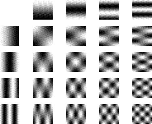
68 Basis Functions
69 Non-linear warping Finding the coefficients is again an optimization problem Strategies: least squares, Gauss-Newton, simplex, gradient descent, genetic algorithms, neural networks Just minimize the cost function.


70 Spatial Normalisation Original image Spatially normalised Determine the spatial transformation that minimises the sum of squared difference between an image and a linear combination of one or more templates. Begins with an affine registration to match the size and position of the image. Spatial Normalisation Followed by a global non-linear warping to match the overall brain shape. Uses a Bayesian framework to simultaneously maximise the smoothness of the warps. Template image slide from SPM website? Deformation field
:165-189 Ashburner & Friston (1997): Multimodal image coregistration and partitioning - a unified framework.")
71 Normalization References Friston et al (1995): Spatial registration and normalisation of images. Human Brain Mapping 3(3): Ashburner & Friston (1997): Multimodal image coregistration and partitioning - a unified framework. NeuroImage 6(3): Collignon et al (1995): Automated multimodality image registration based on information theory. IPMI 95 pp Ashburner et al (1997): Incorporating prior knowledge into image registration. NeuroImage 6(4): Ashburner et al (1999): Nonlinear spatial normalisation using basis functions. Human Brain Mapping 7(4): Ashburner & Friston (2000): Voxel-based morphometry - the methods. NeuroImage 11: slide from SPM website?
72 Practical aspects of spatial normalization Resolution, contrast, Field Of View can be different between template and functional images. Useful to collect additional images to use in the search for the deformation fields, then apply the resulting deformations to the functional images.
73 Whole head image (hi-res, T1 weighted) Practical Normalization Path: Moving between 3 frames of reference S non-linear W 1 T1-weighted overlays (hires, T1 weighted) functional images (hi-res, T2* weighted) F linear transformation non-linear W 2 () (sometimes not enough info ) T Template (med-res, T1 weighted)
74 Typical Normalization path 1. Register whole brain to overlay. e = (F - AS) 2, find A that minimizes e 2. Warp the transformed whole brain image into template e = (T - W 2 (AS) ) 2, find W 2 that minimizes e 3. Use the same warping parameters to warp the functional maps. The end result is: W 2 F S = whole brain image F = functional image T = template image
75 Segmented Normalization Knowledge of brain structure (e.g. grey matter, white matter, CSF) can improve the normalization process Strategy: partition the brain into GM, WM, and CSF and then performs a more informed normalization on the resulting partitions Often results in more consistent normalization Courtesy of Derek Nee
76 Segmented Normalization 1. Use clustering algorithm to calculate intensity distributions of grey matter, white matter, and CSF (additional clusters for eyes and scalp too) 2. Inform clustering algorithm with prior probability maps of GM, WM, and CSF 3. Update probabilities and iterate until convergence 4. Normalize resultant segments to template Note: bias correction is also included in the routine Courtesy of Derek Nee


77 Segmented Normalization Tissue probability maps Normalized tissue maps Segmentation results in original subject space Courtesy of Derek Nee
78 Lecture Goals Understand the following confounds in fmri and what corrections exist Slice Timing effects (temporal shifting) Movement (rigid body realignment) Physiological Artifacts: respiration and heart beat (regression filters) Electronic Noise (filters and autoregressive models) Morphology (non-linear warping) Image distortions ( susceptibility, ghosting, warping)
79 Unwanted Things that can happen to the MR signal Addition of unwanted Signals Coherent at different frequencies Incoherent (spikes) Unwanted frequency shifts Unwanted Phase shifts Multiplication (modulation) by another signal What do these do to the image? (Think Fourier Transform)
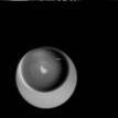
80 White Pixel Artifact Caused by a noise spike during acquisition Spike in K-space <--> sinusoid in image space


81 Not Always Easy to See Top image has spikes, bottom does not Courtesy of Derek Nee Difference of the two images

82 Spikes In Results - Corrected Deviations from -8 to 10 Deviations from -2.5 to 2.5 Courtesy of Derek Nee
83 Despiking How do I know if I have a problem? Look for large changes in global signal Difference images to make spikes more visible Look for large deviations from predicted response How do I fix it? Treat the artifacts as early as possible, either in k- space or in voxel-space before other preprocessing steps have been applied Replace spike with interpolation of neighbors
84 EPI Nyquist ghost Caused by phase-error every other line of k-space (hardware problem - e.g.- sometimes the gradient coils are not well balanced) This means k-space data are modulated along one axis by artefact Artefact is oscillation at the Nyquist frequency. Solution can be easy: 1. add a little bit of phase to alternate lines of k- space and reconstruct. 2. See it the ghosting gets better or worse. 3. Repeat until fixed. G x k x

85 Ghosting and Modulation ( just when you thought you were done with high school trigonometry!)
 Time domain Frequency Domain A(t) B(t) A(t)* B(t)")
86 Ghosting and Modulation ( just when you thought you were done with high school trigonometry!) Time domain Frequency Domain A(t) B(t) A(t)* B(t)

87 EPI Nyquist Ghost K-space sampling Courtesy of P. Jezzard
88 Off-resonance effects (frequency shifts) Recall: w 0 = g B 0 Chemical shift: fat protons have a different gyromagnetic ratio, and hence resonant frequency (3.5ppm away from water) Field distorsions: produce the same effect (changes in B 0 instead of change in g). Both result in a change of w 0 in a particular region What we observe is a change in phase of signal.

89 Examples of Chemical Shift Artifact Images from: Hornak,
")

90 Chemical Shift Artifact (spiral imaging example) High Res. spin echo Spiral Imaging Spiral Imaging after Fat Sat
91 Geometric Distortions spin echo image field map Jezzard and Balaban, MRM 34: warped epi image unwarped epi image
92 Geometric Distortion Caused by Bad shim and/or non-linear gradients. The gradient you want is not always the gradient you get. Solutions: 1. Correct using field maps. 1. Measure B 0 map 2. calculate how much extra phase is due to the inhomogeneity, 3. remove bad phase from data (not easy) 2. correct by warping the image to match an undistorted one (NB These work to a point. Sometimes you can t separate signals that have been pushed together by the artifact, or you can t recover signal from voxels where all the signal is gone completely)
93 Distortions are usually errors or unexpected terms in the Signal Equation S(t) = m(x,y,z)e i2π (k x (t )x +k y (t )y +k z (t )z) dx dy dz k x (t) = γ 2π k y (t) = γ 2π t G x (τ)dτ o t G y (τ)dτ o k z (t) = γ t G z (τ)dτ 2π o + junk + junk + junk

94 Susceptibility Artifacts Off-resonance artifacts caused by adjacent regions with different magnetic Susceptibility BOLD signal requires susceptibility weighting but this also leads to image artifacts No Susceptibility Contrast High Susceptibility Contrast courtesy of Douglas Noll
95 Magnetic Susceptibility Amount of Magnetization of a material produced in response to a magnetic field M = c H Field gets distorted by this magnetization B = µ 0 (1 + c) H

96 Susceptibility Artifacts Magnetic Fields in the Head Low Field Ideal Signal Loss Li et al. Magn. Reson. Med. 36:710 (1996) High Field courtesy of Douglas Noll
97 Susceptibility Artifacts Local gradients Challenges: If severe: Lots of different phases within a voxel. Result is destructive interference: signal loss. If they are more gentle: skewing of the k-space trajectory in different voxels) Solutions: this is an active research field, lots of tricks you can do, but they all have an associated cost in time, SNR, computation, hardware... Choose acquisition parameters such that the artifacts are minimized simplest, usually best! Parallel imaging Z-shimming, active shims Forward-model, iterative reconstructions
98 Intra-oral Diamagnetic Shims Shimming by 1 st, 2 nd and 3 rd order shims provides only modest field correction Magnetic field can be made more uniform through the use of intraoral shims made of diamagnetic materials (Wilson & Jezzard P MRM 50: , 2003)
99 Why are some images affected by off-resonance, but not others? Spin Echoes refocus off-resonance Major factors: How much time you allow the effect to accumulate echo times, readout time How much variation in the magnetic field within the excited volume slice thickness, shim
100 Some Simple Approaches Thinner slices Slower, more slices to cover head Lower SNR Shorter echo time (TE) Reduced contrast to BOLD effect Shorter readout!! Residual Signal Thin Slice Short TE courtesy of Douglas Noll Thick Slice Long TE Echo Time
 TE = 25 ms, 20 ms Single-Shot")
101 Signal Loss vs. Slice Thickness (movie) TE = 25 ms, 20 ms Single-Shot Spiral Acquisition courtesy of Douglas Noll
102 Signal Loss vs. TE (movie) courtesy of Douglas Noll Thickness = 4 mm, 20 ms Single-Shot Spiral Acquisition
103 Susceptibility Distortions from Long Readouts (movie) TE = 10 ms, Thickness = 4 mm, Spiral Acquisition courtesy of Douglas Noll
104 Reducing Readout Length Susceptibility distortions from long acquisition readouts and high field strengths Hardware limits: we can only go so fast! Gradient strength limited by peripheral nerve stimulation Head gradients would be one approach but there are still hardware limits! Parallel imaging (e.g. SENSE) can reduce readout duration More coils collecting less data per coil.


105 Parallel Imaging (see Blaimer et al Topics in MRI, 15, 4, 2004 for review article) SENSE PILS

106 Spiral SENSE Results Head Coil 4-Channel SENSE Coil Reduced Susceptibility Artifact courtesy of Douglas Noll Excellent Detail
107 Putting it all together : pre-processing stream Functional Time Series Anatomical Images despiking B0 map correction Physio correction Reconstruction B1 homogeneity correction Reconstruction brain extraction Slice Timing correction registration Motion- realignment normalization SPM Statistical Map in Standard Space

108 How important is pre-processing? Courtesy of Derek Nee
109 Localized interpolation: the long version The digitized signal in frequency domain F(w) e -iwt rect(w) The signal in time domain f( t ) * sinc(t - t) rect(w) Convolution: f[n]*g[n] = S k f[k] g[n-k] sinc(t) = sin(t) /t
White Pixel Artifact. Caused by a noise spike during acquisition Spike in K-space <--> sinusoid in image space
 White Pixel Artifact Caused by a noise spike during acquisition Spike in K-space sinusoid in image space Susceptibility Artifacts Off-resonance artifacts caused by adjacent regions with different
Functional MRI in Clinical Research and Practice Preprocessing
 Functional MRI in Clinical Research and Practice Preprocessing fmri Preprocessing Slice timing correction Geometric distortion correction Head motion correction Temporal filtering Intensity normalization
SPM8 for Basic and Clinical Investigators. Preprocessing. fmri Preprocessing
 SPM8 for Basic and Clinical Investigators Preprocessing fmri Preprocessing Slice timing correction Geometric distortion correction Head motion correction Temporal filtering Intensity normalization Spatial
Basic fmri Design and Analysis. Preprocessing
 Basic fmri Design and Analysis Preprocessing fmri Preprocessing Slice timing correction Geometric distortion correction Head motion correction Temporal filtering Intensity normalization Spatial filtering
EPI Data Are Acquired Serially. EPI Data Are Acquired Serially 10/23/2011. Functional Connectivity Preprocessing. fmri Preprocessing
 Functional Connectivity Preprocessing Geometric distortion Head motion Geometric distortion Head motion EPI Data Are Acquired Serially EPI Data Are Acquired Serially descending 1 EPI Data Are Acquired
SPM8 for Basic and Clinical Investigators. Preprocessing
 SPM8 for Basic and Clinical Investigators Preprocessing fmri Preprocessing Slice timing correction Geometric distortion correction Head motion correction Temporal filtering Intensity normalization Spatial
MRI Physics II: Gradients, Imaging
 MRI Physics II: Gradients, Imaging Douglas C., Ph.D. Dept. of Biomedical Engineering University of Michigan, Ann Arbor Magnetic Fields in MRI B 0 The main magnetic field. Always on (0.5-7 T) Magnetizes
Computational Neuroanatomy
 Computational Neuroanatomy John Ashburner john@fil.ion.ucl.ac.uk Smoothing Motion Correction Between Modality Co-registration Spatial Normalisation Segmentation Morphometry Overview fmri time-series kernel
This Time. fmri Data analysis
 This Time Reslice example Spatial Normalization Noise in fmri Methods for estimating and correcting for physiologic noise SPM Example Spatial Normalization: Remind ourselves what a typical functional image
Functional MRI data preprocessing. Cyril Pernet, PhD
 Functional MRI data preprocessing Cyril Pernet, PhD Data have been acquired, what s s next? time No matter the design, multiple volumes (made from multiple slices) have been acquired in time. Before getting
Role of Parallel Imaging in High Field Functional MRI
 Role of Parallel Imaging in High Field Functional MRI Douglas C. Noll & Bradley P. Sutton Department of Biomedical Engineering, University of Michigan Supported by NIH Grant DA15410 & The Whitaker Foundation
Fmri Spatial Processing
 Educational Course: Fmri Spatial Processing Ray Razlighi Jun. 8, 2014 Spatial Processing Spatial Re-alignment Geometric distortion correction Spatial Normalization Smoothing Why, When, How, Which Why is
Image Registration + Other Stuff
 Image Registration + Other Stuff John Ashburner Pre-processing Overview fmri time-series Motion Correct Anatomical MRI Coregister m11 m 21 m 31 m12 m13 m14 m 22 m 23 m 24 m 32 m 33 m 34 1 Template Estimate
Introduction to fmri. Pre-processing
 Introduction to fmri Pre-processing Tibor Auer Department of Psychology Research Fellow in MRI Data Types Anatomical data: T 1 -weighted, 3D, 1/subject or session - (ME)MPRAGE/FLASH sequence, undistorted
Journal of Articles in Support of The Null Hypothesis
 Data Preprocessing Martin M. Monti, PhD UCLA Psychology NITP 2016 Typical (task-based) fmri analysis sequence Image Pre-processing Single Subject Analysis Group Analysis Journal of Articles in Support
FMRI Pre-Processing and Model- Based Statistics
 FMRI Pre-Processing and Model- Based Statistics Brief intro to FMRI experiments and analysis FMRI pre-stats image processing Simple Single-Subject Statistics Multi-Level FMRI Analysis Advanced FMRI Analysis
Preprocessing II: Between Subjects John Ashburner
 Preprocessing II: Between Subjects John Ashburner Pre-processing Overview Statistics or whatever fmri time-series Anatomical MRI Template Smoothed Estimate Spatial Norm Motion Correct Smooth Coregister
Methods for data preprocessing
 Methods for data preprocessing John Ashburner Wellcome Trust Centre for Neuroimaging, 12 Queen Square, London, UK. Overview Voxel-Based Morphometry Morphometry in general Volumetrics VBM preprocessing
Imaging Notes, Part IV
 BME 483 MRI Notes 34 page 1 Imaging Notes, Part IV Slice Selective Excitation The most common approach for dealing with the 3 rd (z) dimension is to use slice selective excitation. This is done by applying
XI Signal-to-Noise (SNR)
") XI Signal-to-Noise (SNR) Lecture notes by Assaf Tal n(t) t. Noise. Characterizing Noise Noise is a random signal that gets added to all of our measurements. In D it looks like this: while in D
XI Signal-to-Noise (SNR) Lecture notes by Assaf Tal n(t) t. Noise. Characterizing Noise Noise is a random signal that gets added to all of our measurements. In D it looks like this: while in D
HST.583 Functional Magnetic Resonance Imaging: Data Acquisition and Analysis Fall 2008
 MIT OpenCourseWare http://ocw.mit.edu HST.583 Functional Magnetic Resonance Imaging: Data Acquisition and Analysis Fall 2008 For information about citing these materials or our Terms of Use, visit: http://ocw.mit.edu/terms.
Last Time. This Time. Thru-plane dephasing: worse at long TE. Local susceptibility gradients: thru-plane dephasing
 Motion Correction Last Time Mutual Information Optimiation Decoupling Translation & Rotation Interpolation SPM Example (Least Squares & MI) A Simple Derivation This Time Reslice example SPM Example : Remind
fmri Image Preprocessing
 fmri Image Preprocessing Rick Hoge, Ph.D. Laboratoire de neuroimagerie vasculaire (LINeV) Centre de recherche de l institut universitaire de gériatrie de Montréal, Université de Montréal Outline Motion
Supplementary methods
 Supplementary methods This section provides additional technical details on the sample, the applied imaging and analysis steps and methods. Structural imaging Trained radiographers placed all participants
Diffusion MRI Acquisition. Karla Miller FMRIB Centre, University of Oxford
 Diffusion MRI Acquisition Karla Miller FMRIB Centre, University of Oxford karla@fmrib.ox.ac.uk Diffusion Imaging How is diffusion weighting achieved? How is the image acquired? What are the limitations,
Field Maps. 1 Field Map Acquisition. John Pauly. October 5, 2005
 Field Maps John Pauly October 5, 25 The acquisition and reconstruction of frequency, or field, maps is important for both the acquisition of MRI data, and for its reconstruction. Many of the imaging methods
Module 5: Dynamic Imaging and Phase Sharing. (true-fisp, TRICKS, CAPR, DISTAL, DISCO, HYPR) Review. Improving Temporal Resolution.
 Review. Improving Temporal Resolution.") MRES 7005 - Fast Imaging Techniques Module 5: Dynamic Imaging and Phase Sharing (true-fisp, TRICKS, CAPR, DISTAL, DISCO, HYPR) Review Improving Temporal Resolution True-FISP (I) True-FISP (II) Keyhole
MRES 7005 - Fast Imaging Techniques Module 5: Dynamic Imaging and Phase Sharing (true-fisp, TRICKS, CAPR, DISTAL, DISCO, HYPR) Review Improving Temporal Resolution True-FISP (I) True-FISP (II) Keyhole
MR IMAGE SEGMENTATION
 MR IMAGE SEGMENTATION Prepared by : Monil Shah What is Segmentation? Partitioning a region or regions of interest in images such that each region corresponds to one or more anatomic structures Classification
2. Creating Field Maps Using the Field Map GUI (Version 2.0) in SPM5
 in SPM5") 1. Introduction This manual describes how to use the Field Map Toolbox Version 2.0 for creating unwrapped field maps that can be used to do geometric distortion correction of EPI images in SPM5. 1. 1.
1. Introduction This manual describes how to use the Field Map Toolbox Version 2.0 for creating unwrapped field maps that can be used to do geometric distortion correction of EPI images in SPM5. 1. 1.
A Model-Independent, Multi-Image Approach to MR Inhomogeneity Correction
 Tina Memo No. 2007-003 Published in Proc. MIUA 2007 A Model-Independent, Multi-Image Approach to MR Inhomogeneity Correction P. A. Bromiley and N.A. Thacker Last updated 13 / 4 / 2007 Imaging Science and
Neuroimaging and mathematical modelling Lesson 2: Voxel Based Morphometry
 Neuroimaging and mathematical modelling Lesson 2: Voxel Based Morphometry Nivedita Agarwal, MD Nivedita.agarwal@apss.tn.it Nivedita.agarwal@unitn.it Volume and surface morphometry Brain volume White matter
Functional MRI. Jerry Allison, Ph. D. Medical College of Georgia
 Functional MRI Jerry Allison, Ph. D. Medical College of Georgia BOLD Imaging Technique Blood Oxygen Level Dependent contrast can be used to map brain function Right Hand Motor Task Outline fmri BOLD Contrast
Sources of Distortion in Functional MRI Data
 Human Brain Mapping 8:80 85(1999) Sources of Distortion in Functional MRI Data Peter Jezzard* and Stuart Clare FMRIB Centre, Department of Clinical Neurology, University of Oxford, Oxford, UK Abstract:
fmri pre-processing Juergen Dukart
 fmri pre-processing Juergen Dukart Outline Why do we need pre-processing? fmri pre-processing Slice time correction Realignment Unwarping Coregistration Spatial normalisation Smoothing Overview fmri time-series
HST.583 Functional Magnetic Resonance Imaging: Data Acquisition and Analysis Fall 2006
 MIT OpenCourseWare http://ocw.mit.edu HST.583 Functional Magnetic Resonance Imaging: Data Acquisition and Analysis Fall 2006 For information about citing these materials or our Terms of Use, visit: http://ocw.mit.edu/terms.
Correction of Partial Volume Effects in Arterial Spin Labeling MRI
 Correction of Partial Volume Effects in Arterial Spin Labeling MRI By: Tracy Ssali Supervisors: Dr. Keith St. Lawrence and Udunna Anazodo Medical Biophysics 3970Z Six Week Project April 13 th 2012 Introduction
Fast Imaging Trajectories: Non-Cartesian Sampling (1)
") Fast Imaging Trajectories: Non-Cartesian Sampling (1) M229 Advanced Topics in MRI Holden H. Wu, Ph.D. 2018.05.03 Department of Radiological Sciences David Geffen School of Medicine at UCLA Class Business
Fast Imaging Trajectories: Non-Cartesian Sampling (1) M229 Advanced Topics in MRI Holden H. Wu, Ph.D. 2018.05.03 Department of Radiological Sciences David Geffen School of Medicine at UCLA Class Business
Basic principles of MR image analysis. Basic principles of MR image analysis. Basic principles of MR image analysis
 Basic principles of MR image analysis Basic principles of MR image analysis Julien Milles Leiden University Medical Center Terminology of fmri Brain extraction Registration Linear registration Non-linear
Spatial Preprocessing
 Spatial Preprocessing Overview of SPM Analysis fmri time-series Design matrix Statistical Parametric Map John Ashburner john@fil.ion.ucl.ac.uk Motion Correction Smoothing General Linear Model Smoothing
COBRE Scan Information
 COBRE Scan Information Below is more information on the directory structure for the COBRE imaging data. Also below are the imaging parameters for each series. Directory structure: var/www/html/dropbox/1139_anonymized/human:
Slide 1. Technical Aspects of Quality Control in Magnetic Resonance Imaging. Slide 2. Annual Compliance Testing. of MRI Systems.
 Slide 1 Technical Aspects of Quality Control in Magnetic Resonance Imaging Slide 2 Compliance Testing of MRI Systems, Ph.D. Department of Radiology Henry Ford Hospital, Detroit, MI Slide 3 Compliance Testing
Clinical Importance. Aortic Stenosis. Aortic Regurgitation. Ultrasound vs. MRI. Carotid Artery Stenosis
 Clinical Importance Rapid cardiovascular flow quantitation using sliceselective Fourier velocity encoding with spiral readouts Valve disease affects 10% of patients with heart disease in the U.S. Most
Phase Difference Reconstruction. Outline
 Advanced MRI Phase Difference Reconstruction Faik Can MERAL Outline Introduction Quantitative Description Arctangent operation ATAN2 Phased-Array Multiple Coil Data Correction of Predictable Phase Errors
Classification of Subject Motion for Improved Reconstruction of Dynamic Magnetic Resonance Imaging
 1 CS 9 Final Project Classification of Subject Motion for Improved Reconstruction of Dynamic Magnetic Resonance Imaging Feiyu Chen Department of Electrical Engineering ABSTRACT Subject motion is a significant
Steen Moeller Center for Magnetic Resonance research University of Minnesota
 Steen Moeller Center for Magnetic Resonance research University of Minnesota moeller@cmrr.umn.edu Lot of material is from a talk by Douglas C. Noll Department of Biomedical Engineering Functional MRI Laboratory
AFNI Preprocessing: Outline, Recommendations, and New(ish) Stuff. Robert W Cox SSCC / NIMH & NINDS / NIH / DHHS / USA / EARTH
 Stuff. Robert W Cox SSCC / NIMH & NINDS / NIH / DHHS / USA / EARTH") AFNI Preprocessing: Outline, Recommendations, and New(ish) Stuff Robert W Cox SSCC / NIMH & NINDS / NIH / DHHS / USA / EARTH HBM 2016 As a work of a US Government official, this presentation is not copyrighted
AFNI Preprocessing: Outline, Recommendations, and New(ish) Stuff Robert W Cox SSCC / NIMH & NINDS / NIH / DHHS / USA / EARTH HBM 2016 As a work of a US Government official, this presentation is not copyrighted
Motion Correction in fmri by Mapping Slice-to-Volume with Concurrent Field-Inhomogeneity Correction
 Motion Correction in fmri by Mapping Slice-to-Volume with Concurrent Field-Inhomogeneity Correction Desmond T.B. Yeo 1,2, Jeffery A. Fessler 2, and Boklye Kim 1 1 Department of Radiology, University of
Image Processing for fmri John Ashburner. Wellcome Trust Centre for Neuroimaging, 12 Queen Square, London, UK.
 Iage Processing for fmri John Ashburner Wellcoe Trust Centre for Neuroiaging, 12 Queen Square, London, UK. Contents * Preliinaries * Rigid-Body and Affine Transforations * Optiisation and Objective Functions
Image Acquisition Systems
 Image Acquisition Systems Goals and Terminology Conventional Radiography Axial Tomography Computer Axial Tomography (CAT) Magnetic Resonance Imaging (MRI) PET, SPECT Ultrasound Microscopy Imaging ITCS
(a Scrhon5 R2iwd b. P)jc%z 5. ivcr3. 1. I. ZOms Xn,s. 1E IDrAS boms. EE225E/BIOE265 Spring 2013 Principles of MRI. Assignment 8 Solutions
jc%z 5. ivcr3. 1. I. ZOms Xn,s. 1E IDrAS boms. EE225E/BIOE265 Spring 2013 Principles of MRI. Assignment 8 Solutions") EE225E/BIOE265 Spring 2013 Principles of MRI Miki Lustig Assignment 8 Solutions 1. Nishimura 7.1 P)jc%z 5 ivcr3. 1. I Due Wednesday April 10th, 2013 (a Scrhon5 R2iwd b 0 ZOms Xn,s r cx > qs 4-4 8ni6 4
EE225E/BIOE265 Spring 2013 Principles of MRI Miki Lustig Assignment 8 Solutions 1. Nishimura 7.1 P)jc%z 5 ivcr3. 1. I Due Wednesday April 10th, 2013 (a Scrhon5 R2iwd b 0 ZOms Xn,s r cx > qs 4-4 8ni6 4
Module 4. K-Space Symmetry. Review. K-Space Review. K-Space Symmetry. Partial or Fractional Echo. Half or Partial Fourier HASTE
 MRES 7005 - Fast Imaging Techniques Module 4 K-Space Symmetry Review K-Space Review K-Space Symmetry Partial or Fractional Echo Half or Partial Fourier HASTE Conditions for successful reconstruction Interpolation
FSL Pre-Processing Pipeline
 The Art and Pitfalls of fmri Preprocessing FSL Pre-Processing Pipeline Mark Jenkinson FMRIB Centre, University of Oxford FSL Pre-Processing Pipeline Standard pre-processing: Task fmri Resting-state fmri
SPM Introduction. SPM : Overview. SPM: Preprocessing SPM! SPM: Preprocessing. Scott Peltier. FMRI Laboratory University of Michigan
 SPM Introduction Scott Peltier FMRI Laboratory University of Michigan! Slides adapted from T. Nichols SPM! SPM : Overview Library of MATLAB and C functions Graphical user interface Four main components:
SPM Introduction SPM! Scott Peltier. FMRI Laboratory University of Michigan. Software to perform computation, manipulation and display of imaging data
 SPM Introduction Scott Peltier FMRI Laboratory University of Michigan Slides adapted from T. Nichols SPM! Software to perform computation, manipulation and display of imaging data 1 1 SPM : Overview Library
MRI image formation 8/3/2016. Disclosure. Outlines. Chen Lin, PhD DABR 3. Indiana University School of Medicine and Indiana University Health
 MRI image formation Indiana University School of Medicine and Indiana University Health Disclosure No conflict of interest for this presentation 2 Outlines Data acquisition Spatial (Slice/Slab) selection
FSL Pre-Processing Pipeline
 The Art and Pitfalls of fmri Preprocessing FSL Pre-Processing Pipeline Mark Jenkinson FMRIB Centre, University of Oxford FSL Pre-Processing Pipeline Standard pre-processing: Task fmri Resting-state fmri
6 credits. BMSC-GA Practical Magnetic Resonance Imaging II
 BMSC-GA 4428 - Practical Magnetic Resonance Imaging II 6 credits Course director: Ricardo Otazo, PhD Course description: This course is a practical introduction to image reconstruction, image analysis
CHAPTER 9: Magnetic Susceptibility Effects in High Field MRI
 Figure 1. In the brain, the gray matter has substantially more blood vessels and capillaries than white matter. The magnified image on the right displays the rich vasculature in gray matter forming porous,
HST.583 Functional Magnetic Resonance Imaging: Data Acquisition and Analysis Fall 2008
 MIT OpenCourseWare http://ocw.mit.edu HST.583 Functional Magnetic Resonance Imaging: Data Acquisition and Analysis Fall 2008 For information about citing these materials or our Terms of Use, visit: http://ocw.mit.edu/terms.
Brain Extraction, Registration & EPI Distortion Correction
 Brain Extraction, Registration & EPI Distortion Correction What use is Registration? Some common uses of registration: Combining across individuals in group studies: including fmri & diffusion Quantifying
M R I Physics Course
 M R I Physics Course Multichannel Technology & Parallel Imaging Nathan Yanasak, Ph.D. Jerry Allison Ph.D. Tom Lavin, B.S. Department of Radiology Medical College of Georgia References: 1) The Physics of
Statistical Analysis of Neuroimaging Data. Phebe Kemmer BIOS 516 Sept 24, 2015
 Statistical Analysis of Neuroimaging Data Phebe Kemmer BIOS 516 Sept 24, 2015 Review from last time Structural Imaging modalities MRI, CAT, DTI (diffusion tensor imaging) Functional Imaging modalities
SIEMENS MAGNETOM TrioTim syngo MR B17
 \\USER\KNARRGROUP\MultiBand\LavretskyMultiBand\trufi localizer 3-plane TA: 5.1 s PAT: Voxel size: 1.2 1.2 5. Rel. SNR: 1.00 SIEMENS: trufi Load to stamp Slice group 1 Slices 1 Dist. factor 20 % Phase enc.
The SIMRI project A versatile and interactive MRI simulator *
 COST B21 Meeting, Lodz, 6-9 Oct. 2005 The SIMRI project A versatile and interactive MRI simulator * H. Benoit-Cattin 1, G. Collewet 2, B. Belaroussi 1, H. Saint-Jalmes 3, C. Odet 1 1 CREATIS, UMR CNRS
Preprocessing of fmri data
 Preprocessing of fmri data Pierre Bellec CRIUGM, DIRO, UdM Flowchart of the NIAK fmri preprocessing pipeline fmri run 1 fmri run N individual datasets CIVET NUC, segmentation, spatial normalization slice
Cocozza S., et al. : ALTERATIONS OF FUNCTIONAL CONNECTIVITY OF THE MOTOR CORTEX IN FABRY'S DISEASE: AN RS-FMRI STUDY
 ALTERATIONS OF FUNCTIONAL CONNECTIVITY OF THE MOTOR CORTEX IN FABRY'S DISEASE: AN RS-FMRI STUDY SUPPLEMENTARY MATERIALS Sirio Cocozza, MD 1*, Antonio Pisani, MD, PhD 2, Gaia Olivo, MD 1, Francesco Saccà,
Pre-processing of ASL data T CT
 Wed October 2, 2013 Image Processing Pre-processing: motion correction, denoising, outlier detection Alessandra Bertoldo Pre-processing of ASL data T CT C T C Single TI ASL T T T T C CCC average Pre-processing
An Introduction To Automatic Tissue Classification Of Brain MRI. Colm Elliott Mar 2014
 An Introduction To Automatic Tissue Classification Of Brain MRI Colm Elliott Mar 2014 Tissue Classification Tissue classification is part of many processing pipelines. We often want to classify each voxel
Following on from the two previous chapters, which considered the model of the
 Chapter 5 Simulator validation Following on from the two previous chapters, which considered the model of the simulation process and how this model was implemented in software, this chapter is concerned
First-level fmri modeling
 First-level fmri modeling Monday, Lecture 3 Jeanette Mumford University of Wisconsin - Madison What do we need to remember from the last lecture? What is the general structure of a t- statistic? How about
Image Registration Lecture 4: First Examples
 Image Registration Lecture 4: First Examples Prof. Charlene Tsai Outline Example Intensity-based registration SSD error function Image mapping Function minimization: Gradient descent Derivative calculation
Exam 8N080 - Introduction MRI
 Exam 8N080 - Introduction MRI Friday January 23 rd 2015, 13.30-16.30h For this exam you may use an ordinary calculator (not a graphical one). In total there are 6 assignments and a total of 65 points can
surface Image reconstruction: 2D Fourier Transform
 2/1/217 Chapter 2-3 K-space Intro to k-space sampling (chap 3) Frequenc encoding and Discrete sampling (chap 2) Point Spread Function K-space properties K-space sampling principles (chap 3) Basic Contrast
MB-EPI PCASL. Release Notes for Version February 2015
 MB-EPI PCASL Release Notes for Version 1.0 20 February 2015 1 Background High-resolution arterial spin labeling (ASL) imaging is highly desirable in both neuroscience research and clinical applications
Lab Location: MRI, B2, Cardinal Carter Wing, St. Michael s Hospital, 30 Bond Street
 Lab Location: MRI, B2, Cardinal Carter Wing, St. Michael s Hospital, 30 Bond Street MRI is located in the sub basement of CC wing. From Queen or Victoria, follow the baby blue arrows and ride the CC south
Sparse sampling in MRI: From basic theory to clinical application. R. Marc Lebel, PhD Department of Electrical Engineering Department of Radiology
 Sparse sampling in MRI: From basic theory to clinical application R. Marc Lebel, PhD Department of Electrical Engineering Department of Radiology Objective Provide an intuitive overview of compressed sensing
MEDICAL IMAGE ANALYSIS
 SECOND EDITION MEDICAL IMAGE ANALYSIS ATAM P. DHAWAN g, A B IEEE Engineering in Medicine and Biology Society, Sponsor IEEE Press Series in Biomedical Engineering Metin Akay, Series Editor +IEEE IEEE PRESS
Analysis of Functional MRI Timeseries Data Using Signal Processing Techniques
 Analysis of Functional MRI Timeseries Data Using Signal Processing Techniques Sea Chen Department of Biomedical Engineering Advisors: Dr. Charles A. Bouman and Dr. Mark J. Lowe S. Chen Final Exam October
Chapter 3 Set Redundancy in Magnetic Resonance Brain Images
 16 Chapter 3 Set Redundancy in Magnetic Resonance Brain Images 3.1 MRI (magnetic resonance imaging) MRI is a technique of measuring physical structure within the human anatomy. Our proposed research focuses
Preprocessing I: Within Subject John Ashburner
 Preprocessing I: Within Subject John Ashburner Pre-processing Overview Statistics or whatever fmri tie-series Anatoical MRI Teplate Soothed Estiate Spatial Nor Motion Correct Sooth Coregister 11 21 31
Locating Motion Artifacts in Parametric fmri Analysis
 Tina Memo No. 200-002 Presented at MICCAI 999 Locating Motion Artifacts in Parametric fmri Analysis A.J.Lacey, N.A.Thacker, E. Burton, and A.Jackson Last updated 2 / 02 / 2002 Imaging Science and Biomedical
ASAP_2.0 (Automatic Software for ASL Processing) USER S MANUAL
 USER S MANUAL") ASAP_2.0 (Automatic Software for ASL Processing) USER S MANUAL ASAP was developed as part of the COST Action "Arterial Spin Labelling Initiative in Dementia (AID)" by: Department of Neuroimaging, Institute
ASAP_2.0 (Automatic Software for ASL Processing) USER S MANUAL ASAP was developed as part of the COST Action "Arterial Spin Labelling Initiative in Dementia (AID)" by: Department of Neuroimaging, Institute
Midterm Review
 Midterm Review - 2017 EE369B Concepts Noise Simulations with Bloch Matrices, EPG Gradient Echo Imaging 1 About the Midterm Monday Oct 30, 2017. CCSR 4107 Up to end of C2 1. Write your name legibly on this
MEDICAL IMAGE COMPUTING (CAP 5937) LECTURE 4: Pre-Processing Medical Images (II)
 LECTURE 4: Pre-Processing Medical Images (II)") SPRING 2016 1 MEDICAL IMAGE COMPUTING (CAP 5937) LECTURE 4: Pre-Processing Medical Images (II) Dr. Ulas Bagci HEC 221, Center for Research in Computer Vision (CRCV), University of Central Florida (UCF),
SPRING 2016 1 MEDICAL IMAGE COMPUTING (CAP 5937) LECTURE 4: Pre-Processing Medical Images (II) Dr. Ulas Bagci HEC 221, Center for Research in Computer Vision (CRCV), University of Central Florida (UCF),
1 Introduction Motivation and Aims Functional Imaging Computational Neuroanatomy... 12
 Contents 1 Introduction 10 1.1 Motivation and Aims....... 10 1.1.1 Functional Imaging.... 10 1.1.2 Computational Neuroanatomy... 12 1.2 Overview of Chapters... 14 2 Rigid Body Registration 18 2.1 Introduction.....
Partial k-space Reconstruction
 Chapter 2 Partial k-space Reconstruction 2.1 Motivation for Partial k- Space Reconstruction a) Magnitude b) Phase In theory, most MRI images depict the spin density as a function of position, and hence
Accelerated MRI Techniques: Basics of Parallel Imaging and Compressed Sensing
 Accelerated MRI Techniques: Basics of Parallel Imaging and Compressed Sensing Peng Hu, Ph.D. Associate Professor Department of Radiological Sciences PengHu@mednet.ucla.edu 310-267-6838 MRI... MRI has low
MR Advance Techniques. Vascular Imaging. Class III
 MR Advance Techniques Vascular Imaging Class III 1 Vascular Imaging There are several methods that can be used to evaluate the cardiovascular systems with the use of MRI. MRI will aloud to evaluate morphology
SIEMENS MAGNETOM Avanto syngo MR B15
 \\USER\INVESTIGATORS\Ravi\ADNI-phantom\QC Phantom-Localizer TA: 0:10 PAT: Voxel size: 1.9 1.5 8.0 mm Rel. SNR: 1.00 SIEMENS: gre Properties Prio Recon Before measurement After measurement Load to viewer
Correction for EPI Distortions Using Multi-Echo Gradient-Echo Imaging
 Correction for EPI Distortions Using Multi-Echo Gradient-Echo Imaging Nan-kuei Chen and Alice M. Wyrwicz* Magnetic Resonance in Medicine 41:1206 1213 (1999) A novel and effective technique is described
Compressed Sensing for Rapid MR Imaging
 Compressed Sensing for Rapid Imaging Michael Lustig1, Juan Santos1, David Donoho2 and John Pauly1 1 Electrical Engineering Department, Stanford University 2 Statistics Department, Stanford University rapid
XI Conference "Medical Informatics & Technologies" VALIDITY OF MRI BRAIN PERFUSION IMAGING METHOD
 XI Conference "Medical Informatics & Technologies" - 2006 medical imaging, MRI, brain perfusion Bartosz KARCZEWSKI 1, Jacek RUMIŃSKI 1 VALIDITY OF MRI BRAIN PERFUSION IMAGING METHOD Brain perfusion imaging
High Fidelity Brain Connectivity Imaging
 CNI Inauguration Workshop Stanford, March 22 nd, 2012 High Fidelity Brain Connectivity Imaging -Recent Progress on Diffusion Weighted MRI for High Resolution and Low Distortion Allen W. Song, PhD Brain
Introduction to Neuroimaging Janaina Mourao-Miranda
 Introduction to Neuroimaging Janaina Mourao-Miranda Neuroimaging techniques have changed the way neuroscientists address questions about functional anatomy, especially in relation to behavior and clinical
Analysis of fmri data within Brainvisa Example with the Saccades database
 Analysis of fmri data within Brainvisa Example with the Saccades database 18/11/2009 Note : All the sentences in italic correspond to informations relative to the specific dataset under study TP participants
Lucy Phantom MR Grid Evaluation
 Lucy Phantom MR Grid Evaluation Anil Sethi, PhD Loyola University Medical Center, Maywood, IL 60153 November 2015 I. Introduction: The MR distortion grid, used as an insert with Lucy 3D QA phantom, is
SIEMENS MAGNETOM Verio syngo MR B17
 \\USER\Dr. Behrmann\routine\Ilan\ep2d_bold_PMU_resting TA: 8:06 PAT: Voxel size: 3.03.03.0 mm Rel. SNR: 1.00 USER: ep2d_bold_pmu Properties Special sat. Prio Recon System Before measurement Body After
Partial k-space Recconstruction
 Partial k-space Recconstruction John Pauly September 29, 2005 1 Motivation for Partial k-space Reconstruction a) Magnitude b) Phase In theory, most MRI images depict the spin density as a function of position,
Enhao Gong, PhD Candidate, Electrical Engineering, Stanford University Dr. John Pauly, Professor in Electrical Engineering, Stanford University Dr.
 Enhao Gong, PhD Candidate, Electrical Engineering, Stanford University Dr. John Pauly, Professor in Electrical Engineering, Stanford University Dr. Greg Zaharchuk, Associate Professor in Radiology, Stanford
Motion Artifacts and Suppression in MRI At a Glance
 Motion Artifacts and Suppression in MRI At a Glance Xiaodong Zhong, PhD MR R&D Collaborations Siemens Healthcare MRI Motion Artifacts and Suppression At a Glance Outline Background Physics Common Motion