CSE Real Time Rendering Week 10
|
|
|
- Jodie French
- 6 years ago
- Views:
Transcription
1 CSE Real Time Rendering Week 10
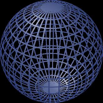
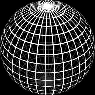
2 Spheres
3 GLUT void glutsolidsphere(gldouble radius, GLint slices, GLint stacks); void glutwiresphere(gldouble radius, GLint slices, GLint stacks);

4 Direct Method
5 GL_LINE_LOOP

6 Problems poles
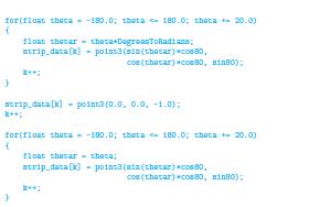
7 Use GL_TRIANGLE FAN
8 Method II
9 YAS (Yet Another Solution)

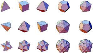
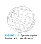
10 Platonic Solids
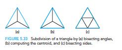
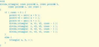
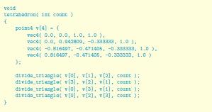
11 Procedure Create Platonic Solid Subdivide each face
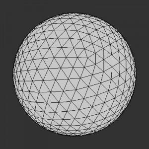
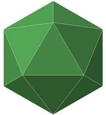
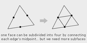
12 Think Sierpinski-like
13 Method III
14
15 Impostor Spheres
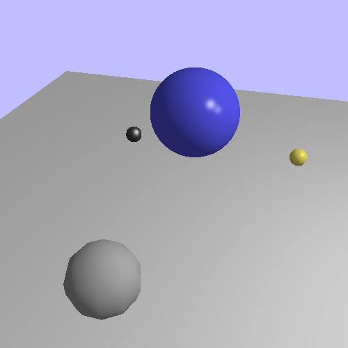
16 Impostors
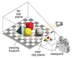
17 Clipping and Scan Conversion

18 Cohen Sutherland in 3D Use 6-bit outcodes When needed, clip line segment against planes
19 Liang-Barsky Clipping In (a): a 4 > a 3 > a 2 > a 1 Intersect right, top, left, bottom: shorten In (b): a 4 > a 2 > a 3 > a 1 Intersect right, left, top, bottom: reject

20 Polygon Clipping Not as simple as line segment clipping Clipping a line segment yields at most one line segment Clipping a polygon can yield multiple polygons Convex polygon is cool J 20
21 Fixes
22 Tessellation and Convexity Replace nonconvex (concave) polygons with triangular polygons (a tessellation) 22
23 Clipping as a Black Box Line segment clipping - takes in two vertices and produces either no vertices or vertices of a clipped segment 23
24 Pipeline Clipping - Line Segments Clipping side of window is independent of other sides Can use four independent clippers in a pipeline 24

25 Pipeline Clipping of Polygons Three dimensions: add front and back clippers Small increase in latency 25
26 Bounding Boxes Ue an axis-aligned bounding box or extent Smallest rectangle aligned with axes that encloses the polygon Simple to compute: max and min of x and y 26
27 Bounding boxes Can usually determine accept/reject based only on bounding box reject accept requires detailed clipping 27
28 Clipping vs. Visibility Clipping similar to hidden-surface removal Remove objects that are not visible to the camera Use visibility or occlusion testing early in the process to eliminate as many polygons as possible before going through the entire pipeline 28
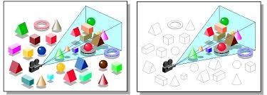
29 Clipping
 partially obscuring can draw independently Worst case complexity O(n 2 ) for n")
30 Hidden Surface Removal Object-space approach: use pairwise testing between polygons (objects) partially obscuring can draw independently Worst case complexity O(n 2 ) for n polygons 30

31 Better Still

32 Better Still
33 Painter s Algorithm Render polygons a back to front order so that polygons behind others are simply painted over B behind A as seen by viewer Fill B then A 33
34 Depth Sort Requires ordering of polygons first O(n log n) calculation for ordering Not all polygons front or behind all other polygons Order polygons and deal with easy cases first, harder later Polygons sorted by distance from COP 34
35 Easy Cases A lies behind all other polygons Can render Polygons overlap in z but not in either x or y Can render independently 35


36 Hard Cases Overlap in all directions but can one is fully on one side of the other cyclic overlap penetration 36
37 Back-Face Removal (Culling) face is visible iff 90 θ -90 equivalently cos θ 0 or v n 0 θ - plane of face has form ax + by +cz +d =0 - After normalization n = ( ) T + Need only test the sign of c - Will not work correctly if we have nonconvex objects 37
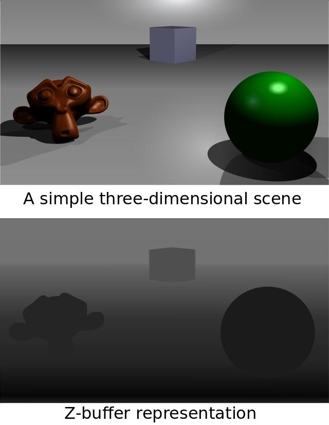
38 Image Space Approach Look at each ray (nm for an n x m frame buffer) Find closest of k polygons Complexity O(nmk) Ray tracing z-buffer 38
39 z-buffer Algorithm Use a buffer called z or depth buffer to store depth of closest object at each pixel found so far As we render each polygon, compare the depth of each pixel to depth in z buffer If less, place shade of pixel in color buffer and update z buffer 39
40 z-buffer for(each polygon P in the polygon list) do{ for(each pixel(x,y) that intersects P) do{ Calculate z-depth of P at (x,y) If (z-depth < z-buffer[x,y]) then{ z-buffer[x,y]=z-depth; COLOR(x,y)=Intensity of P at(x,y); } #If-programming-for alpha compositing: Else if (COLOR(x,y).opacity < 100%) then{ COLOR(x,y)=Superimpose COLOR(x,y) in front of Intensity of P at(x,y); } #Endif-programming-for } } display COLOR array.
41
42 Efficiency - Scanline As we move across a scan line, the depth changes satisfy aδx+bδy+cδz=0 Along scan line Δy = 0 Δz = - a c Δx In screen space Δx = 1 42

43 Scan-Line Algorithm Combine shading and hsr through scan line algorithm scan line i: no need for depth information, can only be in no or one polygon scan line j: need depth information only when in more than one polygon 43
44 Implementation Need a data structure to store Flag for each polygon (inside/outside) Incremental structure for scan lines that stores which edges are encountered Parameters for planes 44
45 Rasterization Rasterization (scan conversion) Determine which pixels that are inside primitive specified by a set of vertices Produces a set of fragments Fragments have a location (pixel location) and other attributes such color and texture coordinates that are determined by interpolating values at vertices Pixel colors determined later using color, texture, and other vertex properties

46 Diversion
47 Rendering Spheres
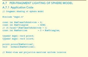
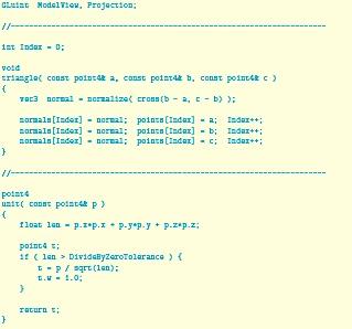
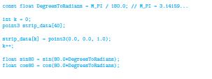
48 Spheres - Application
49 Sphere-Definition

50 Sphere-Lighting
51 VBOs & VAOs

52 Material Properties
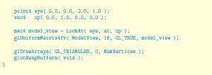
53 The Usual
54 Finally

55 But

56 Vertex Shader Object Space

57 Fragment Shader
58 Yet Another Way
59 Vertex Lighting Shaders I // vertex shader in vec4 vposition; in vec3 vnormal; out vec4 color; //vertex shade // light and material properties uniform vec4 AmbientProduct, DiffuseProduct, SpecularProduct; uniform mat4 ModelView; uniform mat4 Projection; uniform vec4 LightPosition; uniform float Shininess; 59
60 Vertex Lighting Shaders II void main() { // Transform vertex position into eye coordinates vec3 pos = (ModelView * vposition).xyz; vec3 L = normalize( LightPosition.xyz - pos ); vec3 E = normalize( -pos ); vec3 H = normalize( L + E ); // Transform vertex normal into eye coordinates vec3 N = normalize( ModelView*vec4(vNormal, 0.0) ).xyz; 60
61 Vertex Lighting Shaders II void main() { // Transform vertex position into eye coordinates vec3 pos = (ModelView * vposition).xyz; vec3 L = normalize( LightPosition.xyz - pos ); vec3 E = normalize( -pos ); vec3 H = normalize( L + E ); // Transform vertex normal into eye coordinates vec3 N = normalize( ModelView*vec4(vNormal, 0.0) ).xyz; 61
62 Vertex Lighting Shaders III // Compute terms in the illumination equation vec4 ambient = AmbientProduct; float Kd = max( dot(l, N), 0.0 ); vec4 diffuse = Kd*DiffuseProduct; float Ks = pow( max(dot(n, H), 0.0), Shininess ); vec4 specular = Ks * SpecularProduct; if( dot(l, N) < 0.0 ) specular = vec4(0.0, 0.0, 0.0, 1.0); gl_position = Projection * ModelView * vposition; } color = ambient + diffuse + specular; color.a = 1.0; 62
63 Vertex Lighting Shaders IV // fragment shader in vec4 color; void main() { gl_fragcolor = color; } 63 E. Angel and D. Shreiner: Interactive Computer Graphics 6E Addison-Wesley 2012
64 Scan-Line Rasterization
65 ScanConversion -Line Segments Start with line segment in window coordinates with integer values for endpoints Assume implementation has a write_pixel function Δy m = Δ x y = mx + h
66 DDA Algorithm Digital Differential Analyzer Line y=mx+ h satisfies differential equation dy/dx = m = Dy/Dx = y 2 -y 1 /x 2 -x 1 Along scan line Dx = 1 For(x=x1; x<=x2,ix++) { y+=m; display (x, round(y), line_color) }
67 Problem DDA = for each x plot pixel at closest y Problems for steep lines
68 Bresenham s Algorithm DDA requires one floating point addition per step Eliminate computations through Bresenham s algorithm Consider only 1 m 0 Other cases by symmetry Assume pixel centers are at half integers
69 Main Premise If we start at a pixel that has been written, there are only two candidates for the next pixel to be written into the frame buffer
70 Candidate Pixels 1 m 0 candidates last pixel Note that line could have passed through any part of this pixel
71 Decision Variable d = Δx(b-a) d is an integer d > 0 use upper pixel d < 0 use lower pixel -
72 Incremental Form Inspect d k at x = k d k+1 = d k 2Dy, if d k <0 d k+1 = d k 2(Dy- Dx), otherwise For each x, we need do only an integer addition and test Single instruction on graphics chips
73 Polygon Scan Conversion Scan Conversion = Fill How to tell inside from outside Convex easy Nonsimple difficult Odd even test Count edge crossings
74 Filling in the Frame Buffer Fill at end of pipeline Convex Polygons only Nonconvex polygons assumed to have been tessellated Shades (colors) have been computed for vertices (Gouraud shading) Combine with z-buffer algorithm March across scan lines interpolating shades Incremental work small
75 Using Interpolation C 1 C 2 C 3 specified by glcolor or by vertex shading C 4 determined by interpolating between C 1 and C 2 C 5 determined by interpolating between C 2 and C 3 interpolate between C 4 and C 5 along span C 1 scan line C 4 C 2 C 5 C 3 span

76 Scan Line Fill Can also fill by maintaining a data structure of all intersections of polygons with scan lines Sort by scan line Fill each span vertex order generated by vertex list desired order E. Angel and D. Shreiner: Interactive Computer Graphics 6E Addison-Wesley 2012

77 Data Structure
78 Aliasing Ideal rasterized line should be 1 pixel wide Choosing best y for each x (or visa versa) produces aliased raster lines E. Angel and D. Shreiner: Interactive Computer Graphics 6E Addison-Wesley 2012
79 Antialiasing by Area Averaging Color multiple pixels for each x depending on coverage by ideal line original antialiased magnified

80 Polygon Aliasing Aliasing problems can be serious for polygons Jaggedness of edges Small polygons neglected Need compositing so color of one polygon does not totally determine color of pixel All three polygons should contribute to color
81 Hierarchical Modeling


82 Cars, Robots, Solar System
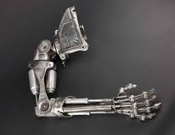
83 The Terminator
84 Our Goal J


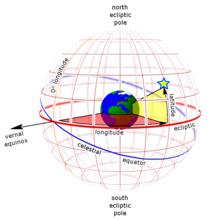
85 Heliocentric Coordinates Heliocentric ecliptic coordinates. The origin is the center of the Sun. The fundamental plane is the plane of the ecliptic. The primary direction (the x axis) is the vernal equinox. A right-handed convention specifies a y axis 90 to the east in the fundamental plane; the z axis points toward the north ecliptic pole. The reference frame is relatively stationary, aligned with the vernal equinox.
86 Inclinations


87 Axial Tilt

88 W. Pedia says To understand axial tilt, we employ the right-hand rule. When the fingers of the right hand are curled around in the direction of the planet's rotation, the thumb points in the direction of the north pole.
 is drawn perpendicular to the plane of each planet's orbit.")
89 Axial Tilts of Planets The axial tilt of three planets: Earth, Uranus, and Venus. Here, a vertical line (black) is drawn perpendicular to the plane of each planet's orbit. The angle between this line and the planet's north pole (red) is the tilt. The surrounding arrows (green) show the direction of the planet's rotation.
90 Ecliptic Coordinate System where \epsilon is the obliquity of the ecliptic.
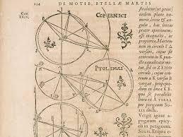
91 Roots
92 Back 2 Earth J
93 Instance Transformation Start with prototype object Each appearance of object in model is instance Must scale, orient, position Defines instance transformation 93
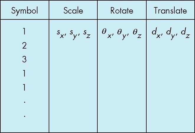
94 Symbol-Instance Table 94
95 Relationships Car Chassis + 4 identical wheels Two symbols Rate of forward motion function of rotational speed of wheels 95
96 Move The Car car(speed) { chassis() wheel(right_front); wheel(left_front); wheel(right_rear); wheel(left_rear); } 96
97 Graphs Composition of Car Set of nodes and edges (links) Edge connects a pair of nodes Directed or undirected Cycle: directed path that is a loop loop 97
98 Tree Composition of Car Graph in which each node (except the root) has exactly one parent node May have multiple children Leaf or terminal node: no children root node leaf node 98

99 Tree Model of Car 99

100 DAG Model All the wheels are identical Not much different than dealing with a tree 100
101 Robot Arm robot arm parts in their own coodinate systems 101
102 Articulated Models Parts connected at joints Specify state of model by joint angles 102
103 Relationships - Composition - Base - Lower Arm - Upper Arm 103
104 Base - Single angle determines position - Is cylinder
105 Lower Arm Attached to base Position depends on rotation of base Also translate relative to base, rotate about connecting joint Is cube
106 Upper Arm Upper arm attached to lower arm Its position depends on both base and lower arm Translate relative to lower arm and rotate about joint connecting to lower arm
107 Upper Arm Upper arm attached to lower arm Its position depends on both base and lower arm Translate relative to lower arm and rotate about joint connecting to lower arm
108 Do the same
109 Required Matrices 109
110 Base Rotation of base: R b Apply M = R b to base
111 Lower Arm Translate lower arm relative to base: T lu Rotate lower arm around joint: R lu Apply M = R b T lu R lu to lower arm
112 Upper Arm Translate upper arm relative to upper arm: T uu Rotate upper arm around joint: R uu Apply M = R b T lu R lu T uu R uu to upper arm
113 Simple Robot mat4 ctm; robot_arm() { ctm = RotateY(theta); base(); ctm *= Translate(0.0, h1, 0.0); ctm *= RotateZ(phi); lower_arm(); ctm *= Translate(0.0, h2, 0.0); ctm *= RotateZ(psi); upper_arm(); } 113

114 Tree Model of Robot Code shows relationships between parts of model Can change shape/texture w/o altering relationships 114

115 Possible Node Structure Code for drawing part or pointer to drawing function linked list of pointers to children matrix relating node to parent 115
116 Do the same
117 Generalizations
118 Generalizations Need to deal with multiple children How do we represent a more general tree? How do we traverse such a data structure? Animation How to use dynamically? Can we create and delete nodes during execution? 118
119 Breadth-First Tree 119
120 Solar System?

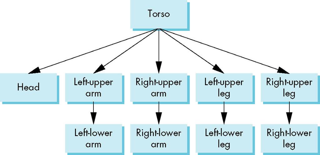
121 Humanoid Figure 121
122 Building the Model Implementation using quadrics: ellipsoids and cylinders Access parts through functions torso() left_upper_arm() Matrices describe position of node with respect to parent M lla positions leftlowerleg with respect to leftupperarm 122
123 Matrices Tree 123
124 Display and Traversal The position determined by 11 joint angles (two for the head and one for each other part) Display of the tree requires a graph traversal Visit each node once Display function at each node pertaining to part Applying correct transformation matrix for position and orientation 124
125 Transformation Matrices 10 relevant matrices M positions and orients entire figure through the torso which is the root node M h positions head with respect to torso M lua, M rua, M lul, M rul position arms and legs with respect to torso M lla, M rla, M lll, M rll position lower parts of limbs with respect to corresponding upper limbs 125
126 Stack-based Traversal Set model-view matrix to M and draw torso Set model-view matrix to MM h and draw head For left-upper arm need MM lua and so on No need recomputing Mm lua Use the matrix stack to store M and other matrices in tree traversal 126
127 Old Style GL Code figure() { PushMatrix() torso(); Rotate ( ); head(); PopMatrix(); PushMatrix(); Translate( ); Rotate( ); left_upper_arm(); PopMatrix(); PushMatrix(); 127 save present model-view matrix update model-view matrix for head recover original model-view matrix save it again update model-view matrix for left upper arm recover and save original model-view matrix again rest of code
128 Tree Data Structure Represent tree and algorithm to traverse tree We will use a left-child right sibling structure Uses linked lists Each node in data structure is two pointers Left: next node Right: linked list of children 128
129 In GLSL
130 In GLSL
131 Still Use
132 Left-Child Right-Sibling Tree 132
133 Tree node Structure At each node - Pointer to sibling Pointer to child Pointer to a function that draws the object represented by the node Homogeneous coordinate matrix to multiply on the right of the current model-view matrix Represents changes going from parent to node In OpenGL this matrix is a 1D array storing matrix by columns 133
134 C typedef struct treenode { mat4 m; void (*f)(); struct treenode *sibling; struct treenode *child; } treenode; 134
135 torso and head nodes treenode torso_node, head_node, lua_node, ; torso_node.m = RotateY(theta[0]); torso_node.f = torso; torso_node.sibling = NULL; torso_node.child = &head_node; head_node.m = translate(0.0, TORSO_HEIGHT +0.5*HEAD_HEIGHT, 0.0)*RotateX(theta[1])*RotateY(theta[2]); head_node.f = head; head_node.sibling = &lua_node; head_node.child = NULL; 135
136 Notes Position determined by 11 joint angles in theta[11] Animate by changing angles and redisplaying Form required matrices using Rotate and Translate 136
137 Preorder Traversal void traverse(treenode* root) { if(root==null) return; mvstack.push(model_view); model_view = model_view*root->m; root->f(); if(root->child!=null) traverse(root->child); model_view = mvstack.pop(); if(root->sibling!=null) traverse(root->sibling); } 137
138 Notes Save model-view matrix before multiplying it by node matrix Updated matrix applies to children but not to siblings Traversal applies to any left-child right-sibling tree Particular tree encoded in definition of individual nodes Order of traversal matters given state changes in the functions 138
139 Dynamic Trees Use pointers, the structure can be dynamic typedef treenode *tree_ptr; tree_ptr torso_ptr; torso_ptr = malloc(sizeof(treenode)); Definition of nodes and traversal are essentially the same as before but we can add and delete nodes during execution 139

140 The Real Thing 140
141 As Opposed
Hierarchical Models Week 9, Lecture 19
 CS Computer Graphics Objectives Hierarchical Models Week, Lecture Examine the limitations of linear modeling - Symbols and instances Introduce hierarchical models - Articulated models - Robots David Breen
Hierarchical Modeling. CS 432 Interactive Computer Graphics Prof. David E. Breen Department of Computer Science
 Hierarchical Modeling CS 432 Interactive Computer Graphics Prof. David E. Breen Department of Computer Science 1 Objectives Examine the limitations of linear modeling - Symbols and instances Introduce
FROM VERTICES TO FRAGMENTS. Lecture 5 Comp3080 Computer Graphics HKBU
 FROM VERTICES TO FRAGMENTS Lecture 5 Comp3080 Computer Graphics HKBU OBJECTIVES Introduce basic implementation strategies Clipping Scan conversion OCTOBER 9, 2011 2 OVERVIEW At end of the geometric pipeline,
Hierarchy I. Guoying Zhao 1 / 40
 Computer Graphics Hierarchy I Guoying Zhao 1 / 40 Hierarchical Modeling I Guoying Zhao 2 / 40 Objectives Examine the limitations of linear modeling Symbols and instances Introduce hierarchical models Articulated
Hierarchical Modeling and Scene Graphs
 Hierarchical Modeling and Scene Graphs Adapted from material prepared by Ed Angel Spring 2009 Objectives Examine the limitations of linear modeling Symbols and instances Introduce hierarchical models Articulated
Hierarchical Modeling and scene graphs
 Hierarchical Modeling and scene graphs Overview Examine the limitations of linear modeling Introduce hierarchical models Introduce Tree and DAG models Build a tree-structured model of a humanoid figure
Topics. From vertices to fragments
 Topics From vertices to fragments From Vertices to Fragments Assign a color to every pixel Pass every object through the system Required tasks: Modeling Geometric processing Rasterization Fragment processing
Hierarchical Modeling II. Ed Angel Professor of Computer Science, Electrical and Computer Engineering, and Media Arts University of New Mexico
 Hierarchical Modeling II Ed Angel Professor of Computer Science, Electrical and Computer Engineering, and Media Arts University of New Mexico Objectives Build a tree-structured model of a humanoid figure
Hierarchical Modeling and Scene Graphs
 Hierarchical Modeling and Scene Graphs Adapted from material prepared by Ed Angel Spring 2009 Objectives Examine the limitations of linear modeling Symbols and instances Introduce hierarchical models Articulated
Hierarchical Modelling
 Gregor Miller gregor{at}ece.ubc.ca Hierarchical Modelling Limitations of linear modelling Articulated models Tree and DAG models Traversal Strategies Instance Transformation Start with a prototype object
Pipeline implementation II
 Pipeline implementation II Overview Line Drawing Algorithms DDA Bresenham Filling polygons Antialiasing Rasterization Rasterization (scan conversion) Determine which pixels that are inside primitive specified
CS452/552; EE465/505. Clipping & Scan Conversion
 CS452/552; EE465/505 Clipping & Scan Conversion 3-31 15 Outline! From Geometry to Pixels: Overview Clipping (continued) Scan conversion Read: Angel, Chapter 8, 8.1-8.9 Project#1 due: this week Lab4 due:
Implementation III. Ed Angel Professor of Computer Science, Electrical and Computer Engineering, and Media Arts University of New Mexico
 Implementation III Ed Angel Professor of Computer Science, Electrical and Computer Engineering, and Media Arts University of New Mexico Objectives Survey Line Drawing Algorithms - DDA - Bresenham 2 Rasterization
Overview. Pipeline implementation I. Overview. Required Tasks. Preliminaries Clipping. Hidden Surface removal
 Overview Pipeline implementation I Preliminaries Clipping Line clipping Hidden Surface removal Overview At end of the geometric pipeline, vertices have been assembled into primitives Must clip out primitives
Clipping. Angel and Shreiner: Interactive Computer Graphics 7E Addison-Wesley 2015
 Clipping 1 Objectives Clipping lines First of implementation algorithms Clipping polygons (next lecture) Focus on pipeline plus a few classic algorithms 2 Clipping 2D against clipping window 3D against
Realtime 3D Computer Graphics Virtual Reality
 Realtime 3D Computer Graphics Virtual Reality From Vertices to Fragments Overview Overall goal recapitulation: Input: World description, e.g., set of vertices and states for objects, attributes, camera,
Hierarchical Modeling I. Angel and Shreiner: Interactive Computer Graphics 7E Addison-Wesley 2015
 Hierarchical Modeling I 1 Objectives Examine the limitations of linear modeling Symbols and instances Introduce hierarchical models Articulated models Robots Introduce Tree and DAG models 2 Instance Transformation
Lecture 17: Shading in OpenGL. CITS3003 Graphics & Animation
 Lecture 17: Shading in OpenGL CITS3003 Graphics & Animation E. Angel and D. Shreiner: Interactive Computer Graphics 6E Addison-Wesley 2012 Objectives Introduce the OpenGL shading methods - per vertex shading
Rendering the Teapot 1
 Rendering the Teapot 1 Utah Teapot 2 Angel and Shreiner: Interactive Computer Graphics 7E Addison-Wesley 2015 vertices.js var numteapotvertices = 306; var vertices = [ vec3(1.4, 0.0, 2.4), vec3(1.4, -0.784,
Objectives Shading in OpenGL. Front and Back Faces. OpenGL shading. Introduce the OpenGL shading methods. Discuss polygonal shading
 Objectives Shading in OpenGL Introduce the OpenGL shading methods - per vertex shading vs per fragment shading - Where to carry out Discuss polygonal shading - Flat - Smooth - Gouraud CITS3003 Graphics
Hierarchical Modeling
 Hierarchical Modeling Geometric Primitives Remember that most graphics APIs have only a few geometric primitives Spheres, cubes, triangles, etc These primitives are instanced in order to apply transforms
Incremental Form. Idea. More efficient if we look at d k, the value of the decision variable at x = k
 Idea 1 m 0 candidates last pixel Note that line could have passed through any part of this pixel Decision variable: d = x(a-b) d is an integer d < 0 use upper pixel d > 0 use lower pixel Incremental Form
Transformations. Rotation and Scaling
 Transformations In OpenGL, transformation are performed in the opposite order they are called 4 3 2 1 translate(1., 1.,.); rotatez(45.); scale(2., 2.,.); DrawSquare(.,., 1.); 4 3 2 1 scale(2., 2.,.); rotatez(45.);
CS354 Computer Graphics Character Animation and Skinning
 Slide Credit: Don Fussell CS354 Computer Graphics Character Animation and Skinning Qixing Huang April 9th 2018 Instance Transformation Start with a prototype object (a symbol) Each appearance of the object
CHAPTER 1 Graphics Systems and Models 3
 ?????? 1 CHAPTER 1 Graphics Systems and Models 3 1.1 Applications of Computer Graphics 4 1.1.1 Display of Information............. 4 1.1.2 Design.................... 5 1.1.3 Simulation and Animation...........
Computer Graphics (CS 543) Lecture 8a: Per-Vertex lighting, Shading and Per-Fragment lighting
 Lecture 8a: Per-Vertex lighting, Shading and Per-Fragment lighting") Computer Graphics (CS 543) Lecture 8a: Per-Vertex lighting, Shading and Per-Fragment lighting Prof Emmanuel Agu Computer Science Dept. Worcester Polytechnic Institute (WPI) Computation of Vectors To calculate
Computer Graphics (CS 543) Lecture 8a: Per-Vertex lighting, Shading and Per-Fragment lighting Prof Emmanuel Agu Computer Science Dept. Worcester Polytechnic Institute (WPI) Computation of Vectors To calculate
Computer Graphics (CS 543) Lecture 6a: Hierarchical 3D Models. Prof Emmanuel Agu. Computer Science Dept. Worcester Polytechnic Institute (WPI)
 Lecture 6a: Hierarchical 3D Models. Prof Emmanuel Agu. Computer Science Dept. Worcester Polytechnic Institute (WPI)") Computer Graphics (CS 543) Lecture 6a: Hierarchical 3D Models Prof Emmanuel Agu Computer Science Dept. Worcester Polytechnic Institute (WPI) Instance Transformation Start with unique object (a symbol)
Computer Graphics (CS 543) Lecture 6a: Hierarchical 3D Models Prof Emmanuel Agu Computer Science Dept. Worcester Polytechnic Institute (WPI) Instance Transformation Start with unique object (a symbol)
Rasterization, Depth Sorting and Culling
 Rasterization, Depth Sorting and Culling Rastrerzation How can we determine which pixels to fill? Reading Material These slides OH 17-26, OH 65-79 and OH 281-282, by Magnus Bondesson You may also read
Hierarchical Modeling. CS 432 Interactive Computer Graphics Prof. David E. Breen Department of Computer Science
 Hierarchical Modeling CS 432 Interactive Computer Graphics Prof. David E. Breen Department of Computer Science E. Angel and D. Shreiner: Interactive Computer Graphics 6E Addison-Wesley 2012 1 Objectives
Modeling Objects. Modeling. Symbol-Instance Table. Instance Transformation. Each appearance of the object in the model is an instance
 Modeling Objects Modeling Hierarchical Transformations Hierarchical Models Scene Graphs A prototype has a default size, position, and orientation You need to perform modeling transformations to position
From Vertices To Fragments-1
 From Vertices To Fragments-1 1 Objectives Clipping Line-segment clipping polygon clipping 2 Overview At end of the geometric pipeline, vertices have been assembled into primitives Must clip out primitives
Rasterization. Rasterization (scan conversion) Digital Differential Analyzer (DDA) Rasterizing a line. Digital Differential Analyzer (DDA)
 Digital Differential Analyzer (DDA) Rasterizing a line. Digital Differential Analyzer (DDA)") CSCI 420 Computer Graphics Lecture 14 Rasterization Jernej Barbic University of Southern California Scan Conversion Antialiasing [Angel Ch. 6] Rasterization (scan conversion) Final step in pipeline: rasterization
CSCI 420 Computer Graphics Lecture 14 Rasterization Jernej Barbic University of Southern California Scan Conversion Antialiasing [Angel Ch. 6] Rasterization (scan conversion) Final step in pipeline: rasterization
COMP371 COMPUTER GRAPHICS
 COMP371 COMPUTER GRAPHICS LECTURE 14 RASTERIZATION 1 Lecture Overview Review of last class Line Scan conversion Polygon Scan conversion Antialiasing 2 Rasterization The raster display is a matrix of picture
Lighting and Shading II. Angel and Shreiner: Interactive Computer Graphics 7E Addison-Wesley 2015
 Lighting and Shading II 1 Objectives Continue discussion of shading Introduce modified Phong model Consider computation of required vectors 2 Ambient Light Ambient light is the result of multiple interactions
Clipping and Scan Conversion
 15-462 Computer Graphics I Lecture 14 Clipping and Scan Conversion Line Clipping Polygon Clipping Clipping in Three Dimensions Scan Conversion (Rasterization) [Angel 7.3-7.6, 7.8-7.9] March 19, 2002 Frank
Fall CSCI 420: Computer Graphics. 7.1 Rasterization. Hao Li.
 Fall 2015 CSCI 420: Computer Graphics 7.1 Rasterization Hao Li http://cs420.hao-li.com 1 Rendering Pipeline 2 Outline Scan Conversion for Lines Scan Conversion for Polygons Antialiasing 3 Rasterization
CSCI 420 Computer Graphics Lecture 14. Rasterization. Scan Conversion Antialiasing [Angel Ch. 6] Jernej Barbic University of Southern California
![CSCI 420 Computer Graphics Lecture 14. Rasterization. Scan Conversion Antialiasing [Angel Ch. 6] Jernej Barbic University of Southern California](/thumbs/86/93458757.jpg "CSCI 420 Computer Graphics Lecture 14. Rasterization. Scan Conversion Antialiasing [Angel Ch. 6] Jernej Barbic University of Southern California") CSCI 420 Computer Graphics Lecture 14 Rasterization Scan Conversion Antialiasing [Angel Ch. 6] Jernej Barbic University of Southern California 1 Rasterization (scan conversion) Final step in pipeline:
CSCI 420 Computer Graphics Lecture 14 Rasterization Scan Conversion Antialiasing [Angel Ch. 6] Jernej Barbic University of Southern California 1 Rasterization (scan conversion) Final step in pipeline:
Renderer Implementation: Basics and Clipping. Overview. Preliminaries. David Carr Virtual Environments, Fundamentals Spring 2005
 INSTITUTIONEN FÖR SYSTEMTEKNIK LULEÅ TEKNISKA UNIVERSITET Renderer Implementation: Basics and Clipping David Carr Virtual Environments, Fundamentals Spring 2005 Feb-28-05 SMM009, Basics and Clipping 1
CS 130 Final. Fall 2015
 CS 130 Final Fall 2015 Name Student ID Signature You may not ask any questions during the test. If you believe that there is something wrong with a question, write down what you think the question is trying
Painter s HSR Algorithm
 Painter s HSR Algorithm Render polygons farthest to nearest Similar to painter layers oil paint Viewer sees B behind A Render B then A Depth Sort Requires sorting polygons (based on depth) O(n log n) complexity
EECE 478. Learning Objectives. Learning Objectives. Rasterization & Scenes. Rasterization. Compositing
 EECE 478 Rasterization & Scenes Rasterization Learning Objectives Be able to describe the complete graphics pipeline. Describe the process of rasterization for triangles and lines. Compositing Manipulate
Werner Purgathofer
 Einführung in Visual Computing 186.822 Visible Surface Detection Werner Purgathofer Visibility in the Rendering Pipeline scene objects in object space object capture/creation ti modeling viewing projection
Interactive Computer Graphics A TOP-DOWN APPROACH WITH SHADER-BASED OPENGL
 International Edition Interactive Computer Graphics A TOP-DOWN APPROACH WITH SHADER-BASED OPENGL Sixth Edition Edward Angel Dave Shreiner Interactive Computer Graphics: A Top-Down Approach with Shader-Based
graphics pipeline computer graphics graphics pipeline 2009 fabio pellacini 1
 graphics pipeline computer graphics graphics pipeline 2009 fabio pellacini 1 graphics pipeline sequence of operations to generate an image using object-order processing primitives processed one-at-a-time
Pipeline Operations. CS 4620 Lecture Steve Marschner. Cornell CS4620 Spring 2018 Lecture 11
 Pipeline Operations CS 4620 Lecture 11 1 Pipeline you are here APPLICATION COMMAND STREAM 3D transformations; shading VERTEX PROCESSING TRANSFORMED GEOMETRY conversion of primitives to pixels RASTERIZATION
graphics pipeline computer graphics graphics pipeline 2009 fabio pellacini 1
 graphics pipeline computer graphics graphics pipeline 2009 fabio pellacini 1 graphics pipeline sequence of operations to generate an image using object-order processing primitives processed one-at-a-time
CS559 Computer Graphics Fall 2015
 CS559 Computer Graphics Fall 2015 Practice Midterm Exam Time: 2 hrs 1. [XX Y Y % = ZZ%] MULTIPLE CHOICE SECTION. Circle or underline the correct answer (or answers). You do not need to provide a justification
Pipeline Operations. CS 4620 Lecture 14
 Pipeline Operations CS 4620 Lecture 14 2014 Steve Marschner 1 Pipeline you are here APPLICATION COMMAND STREAM 3D transformations; shading VERTEX PROCESSING TRANSFORMED GEOMETRY conversion of primitives
Computer Graphics. Bing-Yu Chen National Taiwan University The University of Tokyo
 Computer Graphics Bing-Yu Chen National Taiwan University The University of Tokyo Hidden-Surface Removal Back-Face Culling The Depth-Sort Algorithm Binary Space-Partitioning Trees The z-buffer Algorithm
Computer Graphics and GPGPU Programming
 Computer Graphics and GPGPU Programming Donato D Ambrosio Department of Mathematics and Computer Science and Center of Excellence for High Performace Computing Cubo 22B, University of Calabria, Rende 87036,
QUESTION BANK 10CS65 : COMPUTER GRAPHICS AND VISUALIZATION
 QUESTION BANK 10CS65 : COMPUTER GRAPHICS AND VISUALIZATION INTRODUCTION OBJECTIVE: This chapter deals the applications of computer graphics and overview of graphics systems and imaging. UNIT I 1 With clear
Institutionen för systemteknik
 Code: Day: Lokal: M7002E 19 March E1026 Institutionen för systemteknik Examination in: M7002E, Computer Graphics and Virtual Environments Number of sections: 7 Max. score: 100 (normally 60 is required
Einführung in Visual Computing
 Einführung in Visual Computing 186.822 Rasterization Werner Purgathofer Rasterization in the Rendering Pipeline scene objects in object space transformed vertices in clip space scene in normalized device
Announcements. Midterms graded back at the end of class Help session on Assignment 3 for last ~20 minutes of class. Computer Graphics
 Announcements Midterms graded back at the end of class Help session on Assignment 3 for last ~20 minutes of class 1 Scan Conversion Overview of Rendering Scan Conversion Drawing Lines Drawing Polygons
CS452/552; EE465/505. Lighting & Shading
 CS452/552; EE465/505 Lighting & Shading 2-17 15 Outline! More on Lighting and Shading Read: Angel Chapter 6 Lab2: due tonight use ASDW to move a 2D shape around; 1 to center Local Illumination! Approximate
From Vertices to Fragments: Rasterization. Reading Assignment: Chapter 7. Special memory where pixel colors are stored.
 From Vertices to Fragments: Rasterization Reading Assignment: Chapter 7 Frame Buffer Special memory where pixel colors are stored. System Bus CPU Main Memory Graphics Card -- Graphics Processing Unit (GPU)
Computer Graphics I Lecture 11
 15-462 Computer Graphics I Lecture 11 Midterm Review Assignment 3 Movie Midterm Review Midterm Preview February 26, 2002 Frank Pfenning Carnegie Mellon University http://www.cs.cmu.edu/~fp/courses/graphics/
Lessons Learned from HW4. Shading. Objectives. Why we need shading. Shading. Scattering
 Lessons Learned from HW Shading CS Interactive Computer Graphics Prof. David E. Breen Department of Computer Science Only have an idle() function if something is animated Set idle function to NULL, when
Visible Surface Detection Methods
 Visible urface Detection Methods Visible-urface Detection identifying visible parts of a scene (also hidden- elimination) type of algorithm depends on: complexity of scene type of objects available equipment
CSE528 Computer Graphics: Theory, Algorithms, and Applications
 CSE528 Computer Graphics: Theory, Algorithms, and Applications Hong Qin State University of New York at Stony Brook (Stony Brook University) Stony Brook, New York 11794--4400 Tel: (631)632-8450; Fax: (631)632-8334
Introduction to Computer Graphics with WebGL
 1 Introduction to Computer Graphics with WebGL Ed Angel Lighting in WebGL WebGL lighting Application must specify - Normals - Material properties - Lights State-based shading functions have been deprecated
Pipeline Operations. CS 4620 Lecture 10
 Pipeline Operations CS 4620 Lecture 10 2008 Steve Marschner 1 Hidden surface elimination Goal is to figure out which color to make the pixels based on what s in front of what. Hidden surface elimination
Orthogonal Projection Matrices. Angel and Shreiner: Interactive Computer Graphics 7E Addison-Wesley 2015
 Orthogonal Projection Matrices 1 Objectives Derive the projection matrices used for standard orthogonal projections Introduce oblique projections Introduce projection normalization 2 Normalization Rather
3D Rendering Pipeline (for direct illumination)
") Clipping 3D Rendering Pipeline (for direct illumination) 3D Primitives 3D Modeling Coordinates Modeling Transformation Lighting 3D Camera Coordinates Projection Transformation Clipping 2D Screen Coordinates
Clipping 3D Rendering Pipeline (for direct illumination) 3D Primitives 3D Modeling Coordinates Modeling Transformation Lighting 3D Camera Coordinates Projection Transformation Clipping 2D Screen Coordinates
GLOBAL EDITION. Interactive Computer Graphics. A Top-Down Approach with WebGL SEVENTH EDITION. Edward Angel Dave Shreiner
 GLOBAL EDITION Interactive Computer Graphics A Top-Down Approach with WebGL SEVENTH EDITION Edward Angel Dave Shreiner This page is intentionally left blank. Interactive Computer Graphics with WebGL, Global
Chapter 8: Implementation- Clipping and Rasterization
 Chapter 8: Implementation- Clipping and Rasterization Clipping Fundamentals Cohen-Sutherland Parametric Polygons Circles and Curves Text Basic Concepts: The purpose of clipping is to remove objects or
Computer Graphics. Bing-Yu Chen National Taiwan University
 Computer Graphics Bing-Yu Chen National Taiwan University Visible-Surface Determination Back-Face Culling The Depth-Sort Algorithm Binary Space-Partitioning Trees The z-buffer Algorithm Scan-Line Algorithm
Rasterization Computer Graphics I Lecture 14. Scan Conversion Antialiasing Compositing [Angel, Ch , ]
![Rasterization Computer Graphics I Lecture 14. Scan Conversion Antialiasing Compositing [Angel, Ch , ]](/thumbs/82/86455385.jpg "Rasterization Computer Graphics I Lecture 14. Scan Conversion Antialiasing Compositing [Angel, Ch , ]") 15-462 Computer Graphics I Lecture 14 Rasterization March 13, 2003 Frank Pfenning Carnegie Mellon University http://www.cs.cmu.edu/~fp/courses/graphics/ Scan Conversion Antialiasing Compositing [Angel,
15-462 Computer Graphics I Lecture 14 Rasterization March 13, 2003 Frank Pfenning Carnegie Mellon University http://www.cs.cmu.edu/~fp/courses/graphics/ Scan Conversion Antialiasing Compositing [Angel,
UNIT -8 IMPLEMENTATION
 UNIT -8 IMPLEMENTATION 1. Discuss the Bresenham s rasterization algorithm. How is it advantageous when compared to other existing methods? Describe. (Jun2012) 10M Ans: Consider drawing a line on a raster
Today s Agenda. Basic design of a graphics system. Introduction to OpenGL
 Today s Agenda Basic design of a graphics system Introduction to OpenGL Image Compositing Compositing one image over another is most common choice can think of each image drawn on a transparent plastic
Computer Graphics (CS 4731) Lecture 18: Lighting, Shading and Materials (Part 3)
 Lecture 18: Lighting, Shading and Materials (Part 3)") Computer Graphics (CS 4731) Lecture 18: Lighting, Shading and Materials (Part 3) Prof Emmanuel Agu Computer Science Dept. Worcester Polytechnic Institute (WPI) Recall: Flat Shading compute lighting once
Computer Graphics (CS 4731) Lecture 18: Lighting, Shading and Materials (Part 3) Prof Emmanuel Agu Computer Science Dept. Worcester Polytechnic Institute (WPI) Recall: Flat Shading compute lighting once
Computer Graphics (CS 543) Lecture 10: Rasterization and Antialiasing
 Lecture 10: Rasterization and Antialiasing") Computer Graphics (CS 543) Lecture 10: Rasterization and Antialiasing Prof Emmanuel Agu Computer Science Dept. Worcester Polytechnic Institute (WPI) Recall: Rasterization Rasterization (scan conversion)
Computer Graphics (CS 543) Lecture 10: Rasterization and Antialiasing Prof Emmanuel Agu Computer Science Dept. Worcester Polytechnic Institute (WPI) Recall: Rasterization Rasterization (scan conversion)
CSE328 Fundamentals of Computer Graphics: Concepts, Theory, Algorithms, and Applications
 CSE328 Fundamentals of Computer Graphics: Concepts, Theory, Algorithms, and Applications Hong Qin Stony Brook University (SUNY at Stony Brook) Stony Brook, New York 11794-4400 Tel: (631)632-8450; Fax:
Rasterization: Geometric Primitives
 Rasterization: Geometric Primitives Outline Rasterizing lines Rasterizing polygons 1 Rasterization: What is it? How to go from real numbers of geometric primitives vertices to integer coordinates of pixels
The University of Calgary
 The University of Calgary Department of Computer Science Final Examination, Questions ENEL/CPSC 555 Computer Graphics Time: 2 Hours Closed Book, calculators are permitted. The questions carry equal weight.
The Traditional Graphics Pipeline
 Last Time? The Traditional Graphics Pipeline Participating Media Measuring BRDFs 3D Digitizing & Scattering BSSRDFs Monte Carlo Simulation Dipole Approximation Today Ray Casting / Tracing Advantages? Ray
Rasterization, or What is glbegin(gl_lines) really doing?
 really doing?") Rasterization, or What is glbegin(gl_lines) really doing? Course web page: http://goo.gl/eb3aa February 23, 2012 Lecture 4 Outline Rasterizing lines DDA/parametric algorithm Midpoint/Bresenham s algorithm
Rasterization, or What is glbegin(gl_lines) really doing? Course web page: http://goo.gl/eb3aa February 23, 2012 Lecture 4 Outline Rasterizing lines DDA/parametric algorithm Midpoint/Bresenham s algorithm
Line Drawing. Foundations of Computer Graphics Torsten Möller
 Line Drawing Foundations of Computer Graphics Torsten Möller Rendering Pipeline Hardware Modelling Transform Visibility Illumination + Shading Perception, Interaction Color Texture/ Realism Reading Angel
Hidden Surface Removal
 Outline Introduction Hidden Surface Removal Hidden Surface Removal Simone Gasparini gasparini@elet.polimi.it Back face culling Depth sort Z-buffer Introduction Graphics pipeline Introduction Modeling Geom
The Traditional Graphics Pipeline
 Last Time? The Traditional Graphics Pipeline Reading for Today A Practical Model for Subsurface Light Transport, Jensen, Marschner, Levoy, & Hanrahan, SIGGRAPH 2001 Participating Media Measuring BRDFs
From Ver(ces to Fragments: Rasteriza(on
 From Ver(ces to Fragments: Rasteriza(on From Ver(ces to Fragments 3D vertices vertex shader rasterizer fragment shader final pixels 2D screen fragments l determine fragments to be covered l interpolate
Lets assume each object has a defined colour. Hence our illumination model is looks unrealistic.
 Shading Models There are two main types of rendering that we cover, polygon rendering ray tracing Polygon rendering is used to apply illumination models to polygons, whereas ray tracing applies to arbitrary
The Traditional Graphics Pipeline
 Final Projects Proposals due Thursday 4/8 Proposed project summary At least 3 related papers (read & summarized) Description of series of test cases Timeline & initial task assignment The Traditional Graphics
CEng 477 Introduction to Computer Graphics Fall 2007
 Visible Surface Detection CEng 477 Introduction to Computer Graphics Fall 2007 Visible Surface Detection Visible surface detection or hidden surface removal. Realistic scenes: closer objects occludes the
Line Drawing. Introduction to Computer Graphics Torsten Möller / Mike Phillips. Machiraju/Zhang/Möller
 Line Drawing Introduction to Computer Graphics Torsten Möller / Mike Phillips Rendering Pipeline Hardware Modelling Transform Visibility Illumination + Shading Perception, Color Interaction Texture/ Realism
Scan Conversion. Drawing Lines Drawing Circles
 Scan Conversion Drawing Lines Drawing Circles 1 How to Draw This? 2 Start From Simple How to draw a line: y(x) = mx + b? 3 Scan Conversion, a.k.a. Rasterization Ideal Picture Raster Representation Scan
Rasterization. CS 4620 Lecture Kavita Bala w/ prior instructor Steve Marschner. Cornell CS4620 Fall 2015 Lecture 16
 Rasterization CS 4620 Lecture 16 1 Announcements A3 due on Thu Will send mail about grading once finalized 2 Pipeline overview you are here APPLICATION COMMAND STREAM 3D transformations; shading VERTEX
Identifying those parts of a scene that are visible from a chosen viewing position, and only process (scan convert) those parts
 those parts") Visible Surface Detection Identifying those parts of a scene that are visible from a chosen viewing position, and only process (scan convert) those parts Two approaches: 1. Object space methods 2. Image
Visible Surface Detection Identifying those parts of a scene that are visible from a chosen viewing position, and only process (scan convert) those parts Two approaches: 1. Object space methods 2. Image
6.837 Introduction to Computer Graphics Assignment 5: OpenGL and Solid Textures Due Wednesday October 22, 2003 at 11:59pm
 6.837 Introduction to Computer Graphics Assignment 5: OpenGL and Solid Textures Due Wednesday October 22, 2003 at 11:59pm In this assignment, you will add an interactive preview of the scene and solid
Hierarchical Models. Roadmap. Importance of shadows. Importance of shadows. Importance of shadows. Importance of shadows
 CSCI 420 Computer Graphics Lecture 8 Hierarchical Models Projections and Shadows Hierarchical Models [Angel Ch. 8] Roadmap Last lecture: Viewing and projection Today: Shadows via projections Hierarchical
GLSL Introduction. Fu-Chung Huang. Thanks for materials from many other people
 GLSL Introduction Fu-Chung Huang Thanks for materials from many other people Programmable Shaders //per vertex inputs from main attribute aposition; attribute anormal; //outputs to frag. program varying
Computer Science 426 Midterm 3/11/04, 1:30PM-2:50PM
 NAME: Login name: Computer Science 46 Midterm 3//4, :3PM-:5PM This test is 5 questions, of equal weight. Do all of your work on these pages (use the back for scratch space), giving the answer in the space
Hidden Surfaces II. Week 9, Mon Mar 15
 University of British Columbia CPSC 314 Computer Graphics Jan-Apr 2010 Tamara Munzner Hidden Surfaces II Week 9, Mon Mar 15 http://www.ugrad.cs.ubc.ca/~cs314/vjan2010 ews yes, I'm granting the request
Computer Graphics. Rendering. by Brian Wyvill University of Calgary. cpsc/enel P 1
 Computer Graphics Rendering by Brian Wyvill University of Calgary cpsc/enel P Rendering Techniques Wire Frame Z Buffer Ray Tracing A Buffer cpsc/enel P 2 Rendering Visible Surface Determination Many Algorithms,
Three Main Themes of Computer Graphics
 Three Main Themes of Computer Graphics Modeling How do we represent (or model) 3-D objects? How do we construct models for specific objects? Animation How do we represent the motion of objects? How do
Course Title: Computer Graphics Course no: CSC209
 Course Title: Computer Graphics Course no: CSC209 Nature of the Course: Theory + Lab Semester: III Full Marks: 60+20+20 Pass Marks: 24 +8+8 Credit Hrs: 3 Course Description: The course coversconcepts of
CSE 167: Introduction to Computer Graphics Lecture #9: Visibility. Jürgen P. Schulze, Ph.D. University of California, San Diego Fall Quarter 2018
 CSE 167: Introduction to Computer Graphics Lecture #9: Visibility Jürgen P. Schulze, Ph.D. University of California, San Diego Fall Quarter 2018 Announcements Midterm Scores are on TritonEd Exams to be
CS184 : Foundations of Computer Graphics Professor David Forsyth Final Examination
 CS184 : Foundations of Computer Graphics Professor David Forsyth Final Examination (Total: 100 marks) Figure 1: A perspective view of a polyhedron on an infinite plane. Cameras and Perspective Rendering
CS602 Midterm Subjective Solved with Reference By WELL WISHER (Aqua Leo)
") CS602 Midterm Subjective Solved with Reference By WELL WISHER (Aqua Leo) www.vucybarien.com Question No: 1 What are the two focusing methods in CRT? Explain briefly. Page no : 26 1. Electrostatic focusing
CS602 Midterm Subjective Solved with Reference By WELL WISHER (Aqua Leo) www.vucybarien.com Question No: 1 What are the two focusing methods in CRT? Explain briefly. Page no : 26 1. Electrostatic focusing
COMP30019 Graphics and Interaction Scan Converting Polygons and Lines
 COMP30019 Graphics and Interaction Scan Converting Polygons and Lines Department of Computer Science and Software Engineering The Lecture outline Introduction Scan conversion Scan-line algorithm Edge coherence