ECE421: Electronics for Instrumentation
|
|
|
- Stephanie Fletcher
- 5 years ago
- Views:
Transcription
1 ECE421: Electronics for Instrumentation Lecture #8: Introduction to FEA & ANSYS Mostafa Soliman, Ph.D. March 23 rd 2015 Mostafa Soliman, Ph.D. 1
2 Outline Introduction to Finite Element Analysis Introduction to ANSYS 3/30/2015
3 The finite element method (FEM) is a numerical technique for solving a mathematical model of a physical problem. The FEM is a computer aided numerical technique for obtaining approximate numerical solutions to a set of equations of calculus that predict the response of physical systems subjected to external influences (like forces, pressure, temperature, voltage, etc). The FEM deals with the physical model instead of the lumped parameters mathematical model, see the second order system example below.
 m, b, and K are the lumped parameters of the system.")
4 Second order system: mass-spring-damper system m x bx Kx F(t) m, b, and K are the lumped parameters of the system.
5 MATLAB Modeling: F FEA Modeling: Force F F Red is minimum deflection Blue is maximum deflection
6 How FEA works: 1. A complex entity is broken up into continuous simple geometric shapes called Elements. 2. Elements are simple geometric shapes like line, triangles, rectangular, pyramids, cubs. 3. Each element has its own shape function which describe the relations among its vertices (Nodes). 4. Each Element in interconnected with its neighbor in all directions by means of Nodes. 5. Any load applied to this single element is distributed to its neighbor correspondingly based on its geometrical features (shape function). 6. The material properties of the complex entity or object are applied to the whole of these elements.
 the elements at the nodes to form an approximate system of equations for the whole structure. 4. Solve the system of equations involving unknown quantities at the nodes (e.g. displacement).")
7 FEA solution procedure: 1. Divide the structure into pieces (elements with nodes). 2. Describe the behavior of the physical quantities on each element. 3. Connect (assemble) the elements at the nodes to form an approximate system of equations for the whole structure. 4. Solve the system of equations involving unknown quantities at the nodes (e.g. displacement). 5. Calculate desired quantities (e.g. stress, strain) at selected elements.

8 Discretization and element types: Modeling and solution with FEA is not easy task hence it is based on solving huge number of equations. As a result, FEA software packages are used for calculations and visualization of the results. In next section we are going to introduce ANSYS as a FEA package.

9 ANSYS: ANSYS is a general-purpose software package based on the finite element analysis (FEA). ANSYS program has many finite element analysis capabilities, ranging from a simple, linear, static analysis to a complex, nonlinear, transient dynamic analysis. ANSYS program has a very interesting feature that is can couple different physics to find the solution, e.g. electrostatic/structural, thermal/structural, etc.
10 Typical ANSYS analysis has three distinct phases: Preprocessing phase: Create the Solid model and the Finite element model (meshed model), Define Material properties, Real constants, and Element type. Solution phase: Defining the analysis type, static, transient, modal, harmonic, etc Loads and constraints are applied to either solid model or finite element model, Solving the simultaneous set of equations that the finite element method generates. Postprocessing phase: Reviewing the results of an analysis. It is an important step in the analysis, because we are trying to understand how the applied loads affect the design, how good the finite element mesh is, and so on.
11 Launching ANSYS: Start > All Programs > ANSYS 12.0 > Mechanical APDL (ANSYS) You can run the ANSYS program in two modes: interactive mode (the default), You exchange information with the computer continuously. You can execute a command by selecting its menu path in the GUI or by typing it in directly. The ANSYS program processes the command in real time. Interactive mode allows you to use the GUI, online help, and various tools to create the engineering model in the graphics window and modify it as you work through the analysis. batch mode, You submit a file of commands to the ANSYS program. This command file may have been generated by a previous ANSYS session, by another program, or by creating a command file with an editor.
12
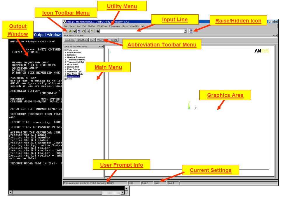
 Input Line: shows program prompt messages and allows to type in commands directly. (3) Toolbar: contains push buttons that execute commonly used ANSYS commands.")
13 (1) Utility Menu: contains functions that are available throughout the ANSYS session, such as file controls, selections, graphic controls, and parameters. (2) Input Line: shows program prompt messages and allows to type in commands directly. (3) Toolbar: contains push buttons that execute commonly used ANSYS commands. More push buttons can be made available if desired. (4) Main Menu: contains the primary ANSYS functions, organized by preprocessor, solution, general postprocessor, and design optimizer. It is from this menu that the vast majority of modeling commands are issued. (5) Graphics Windows: where graphics are shown and graphical picking can be made. It is here where the model in its various stages of construction and the ensuing results from the analysis can be viewed. The Output Window, displays text output from the program, such as listing of data, etc. It is usually positioned behind the Graphics Window and can be put to the front if necessary. Closing output window terminates ANSYS program without saving current data settings.
14 Database and Files: The database stores both your input data and ANSYS results data: - Input data: information to enter, such as dimensions, material properties, and load data. - Results data: quantities that ANSYS calculates, such as displacements, stresses and temperature. Defining the Jobname: Utility Menu > File> Change Jobname The jobname becomes the first part of the name of all files the analysis creates. (The extension or suffix for these files' names is a file identifier such as.db) By using a jobname for each analysis, you ensure that no files are overwritten. Typical files in Ansys: jobname.db,.dbb: Database file, binary. This file stores the geometry, boundary conditions, and any solutions. jobname.log: Log file, ASCII. Contains a log of every command issued during the session. jobname.err: Error file, ASCII. Contains all errors and warnings encountered during the session. jobname.rst,.rth,.rmg,.rfl: Results files, binary. Contains results data calculated by ANSYS during solution. Compatible across all supported platforms.

15 Defining an Analysis Title: Utility Menu> File> Change Title This will define a title for the analysis. ANSYS includes the title on all graphics displays and on the solution output Saving jobs: Utility Menu> File>Save as Jobname.db


16 Restoring jobs: Utility Menu> File> Resume from Exiting the program: Utility Menu> File> Exit

17 UNITS ANSYS does not assume a system of units for intended analysis. Except in magnetic field analyses, any system of units can be used so long as it is ensured that units are consistent for all input data. Units cannot be set directly from the GUI. In order to set units as the international system of units (SI) from Main Menu> Preprocessor Material Props Material Library Units
18 SYSTEM OF UNITS For micro-electromechanical systems (MEMS), it is best to set up problems in more convenient units since components may only be a few microns in size. For convenience, the following tables list the conversion factors from standard MKS units to µmks


19 Defining element types Main Menu> Preprocessor Element Type Add/Edit/Delete.
 Main Menu> Preprocessor Preprocessor Modeling Create Elements Element Attributes")
20 Defining element Attributes In case the model contains many element types and material properties, we need to link each element type with its own material number (or material property) Main Menu> Preprocessor Preprocessor Modeling Create Elements Element Attributes

21 Defining Material Properties We can define any number of material models, each material model is assigned to a certain number. Main Menu> Preprocessor Material Props Material Models

22 Creating Solid Model (Solid Modeling): 1. It is the process of creating solid models in ANSYS environment. 2. A solid model is defined by volumes, areas, lines, and keypoints. 3. Volumes are bounded by areas, areas by lines, and lines by keypoints. 4. Hierarchy of entities from low to high as keypoints < lines < areas < volumes 1. You cannot delete an entity if a higher-order entity is attached to it.
, which are then combined in some fashion to create the final shape. 2.")
23 Methods of Solid Modeling: There are two approaches to build the model: 1. Top-down modeling: starts with a definition of volumes (or areas), which are then combined in some fashion to create the final shape. 2. Bottom-up modeling: Starts with keypoints, from which you build up lines, areas, etc.

24 Methods of Solid Modeling: 3. Primitives: The volumes or areas that you initially define are called primitives, which are basic entities for the top-down method. 4. Work Plane: Working coordinates can move to any point in the working area to facilitate positioning the primitives. By default the WP coincides with the global origin. Utility Menu> WorkPlane> Offset WP by increment > Utility Menu> WorkPlane> Offset WP to > Utility Menu> WorkPlane> Align WP with> XYZ Locations >

25 Methods of Solid Modeling: 5. Boolean Operations: It is the process of combinations of geometric entities Main Menu > Preprocessor > Modeling > Operate > Booleans


26 Methods of Solid Modeling: 5. Boolean Operations: Common boundary
.")
27 Meshing the solid model (Finite Element Model): Main Menu > Preprocessor > Meshing > MeshTool Meshing Methods: There are two main meshing methods: free and mapped. Free Mesh a. Has no element shape restrictions. b. The mesh does not follow any pattern. c. Suitable for complex shaped areas and volumes. d. Volume meshes consist of high order tetrahedral (10 nodes). Mapped Mesh a. Restricts element shapes to quadrilaterals (areas) and hexahedra (volume) b. Typically has a regular pattern with obvious rows of elements. c. Suitable only for regular shapes such as rectangles and bricks.
28 Meshing the solid model (Finite Element Model): Main Menu > Preprocessor > Meshing > MeshTool Mesh density control Smart Sizing: By turning on Smart Sizing, and set the desired size level. Size level ranges from 1 (fine) to 10 (coarse), defaults to 6. Then mesh all volumes (or all areas) at once, rather than one-by-one. Global Element Sizing: Allows you to specify a maximum element edge length for the entire model (or number of divisions per line): MainMenu>Preprocessor>Meshing>SizeCntrls>ManualSize>Glo bal >Size Different entities can be meshed with different element size by using mesh attribute. Main Menu>Preprocessor>Meshing>Mesh Attributes

29 Analysis type: Main Menu > Solution > Analysis Type>

30 Applying loads and constrains: Main Menu > Solution > Define Load> Apply> Structural> Displacement> On Lines

31 Solve: Main Menu > Solution> Solve> Current LS
32 Main Menu > General Postproc> (POST1) Provides the results for only one time step (substep) Main Menu > TimeHist Postpro> (POST26) Provides the results at specific points in the model over all time steps. Postprocessing: 1. Lists or Plots nodal displacements and shows the deformation. 2. Lists Element forces and moments. 3. Lists or Plots Displacement, Stress, or Strain contour diagrams. 4. POST26 is used for transient, harmonic, and modal analyses. 5. POST1 can be used only to review the results of a steady state analysis or the results of only one substep of other analyses.
33 Calculate the spring stiffness (K) and the maximum stress in the MEMS-based cantilever shown below. Verify your calculations using ANSYS. 6 m F 18 m h L
34 area 1 area 2 Preprocessor: 1. Create area 1 and area 2 in the global coordinate system. 2. Glue (or add) area 1 and area Define the element type to be PLANE In the options of the element, select Plane strs w/thk 5. Define the real constant for PLANE 82 (thickness of the beam, 2 µm). 6. Define the material properties. 7. Mesh the whole structure. (refine the mesh) Solution: 1. Apply loads and solve current load step (LS).
35 area 1 area 2 POST1: 1. List displacement in x-direction of all nodes. 2. Plot displacement contour. 3. Plot deformation of the beam. (Animate as well) 4. Plot the stress contour on the plate.
Example Plate with a hole
 Course in ANSYS Example Plate with a hole A Objective: Determine the maximum stress in the x-direction for point A and display the deformation figure Tasks: Create a submodel to increase the accuracy of
Chapter 2. Structural Tutorial
 Chapter 2. Structural Tutorial Tutorials> Chapter 2. Structural Tutorial Static Analysis of a Corner Bracket Problem Specification Problem Description Build Geometry Define Materials Generate Mesh Apply
file://c:\documents and Settings\sala\Configuración local\temp\~hha54f.htm
 Página 1 de 26 Tutorials Chapter 2. Structural Tutorial 2.1. Static Analysis of a Corner Bracket 2.1.1. Problem Specification Applicable ANSYS Products: Level of Difficulty: Interactive Time Required:
ANSYS 5.6 Tutorials Lecture # 2 - Static Structural Analysis
 R50 ANSYS 5.6 Tutorials Lecture # 2 - Static Structural Analysis Example 1 Static Analysis of a Bracket 1. Problem Description: The objective of the problem is to demonstrate the basic ANSYS procedures
INTRODUCTION TO THE SYSTEM
 INTRODUCTION TO THE SYSTEM 1 INTRODUCTION TO THE SYSTEM 1. Introduction The ANSYS computer program is a large-scale multi-purpose finite element program, which may be used for solving several classes of
Finite Element Analysis using ANSYS Mechanical APDL & ANSYS Workbench
 Finite Element Analysis using ANSYS Mechanical APDL & ANSYS Workbench Course Curriculum (Duration: 120 Hrs.) Section I: ANSYS Mechanical APDL Chapter 1: Before you start using ANSYS a. Introduction to
Exercise 1. 3-Point Bending Using the GUI and the Bottom-up-Method
 Exercise 1 3-Point Bending Using the GUI and the Bottom-up-Method Contents Learn how to... 1 Given... 2 Questions... 2 Taking advantage of symmetries... 2 A. Preprocessor (Setting up the Model)... 3 A.1
NonLinear Analysis of a Cantilever Beam
 NonLinear Analysis of a Cantilever Beam Introduction This tutorial was created using ANSYS 7.0 The purpose of this tutorial is to outline the steps required to do a simple nonlinear analysis of the beam
Melting Using Element Death
 Melting Using Element Death Introduction This tutorial was completed using ANSYS 7.0 The purpose of the tutorial is to outline the steps required to use element death to model melting of a material. Element
Two Dimensional Truss
 Two Dimensional Truss Introduction This tutorial was created using ANSYS 7.0 to solve a simple 2D Truss problem. This is the first of four introductory ANSYS tutorials. Problem Description Determine the
ANSYS EXERCISE ANSYS 5.6 Temperature Distribution in a Turbine Blade with Cooling Channels
 I. ANSYS EXERCISE ANSYS 5.6 Temperature Distribution in a Turbine Blade with Cooling Channels Copyright 2001-2005, John R. Baker John R. Baker; phone: 270-534-3114; email: jbaker@engr.uky.edu This exercise
NonLinear Materials AH-ALBERTA Web:
 NonLinear Materials Introduction This tutorial was completed using ANSYS 7.0 The purpose of the tutorial is to describe how to include material nonlinearities in an ANSYS model. For instance, the case
Transient Thermal Conduction Example
 Transient Thermal Conduction Example Introduction This tutorial was created using ANSYS 7.0 to solve a simple transient conduction problem. Special thanks to Jesse Arnold for the analytical solution shown
Chapter 3. Thermal Tutorial
 Chapter 3. Thermal Tutorial Tutorials> Chapter 3. Thermal Tutorial Solidification of a Casting Problem Specification Problem Description Prepare for a Thermal Analysis Input Geometry Define Materials Generate
Exercise 2: Mesh Resolution, Element Shapes, Basis Functions & Convergence Analyses
 Exercise 2: Mesh Resolution, Element Shapes, Basis Functions & Convergence Analyses Goals In this exercise, we will explore the strengths and weaknesses of different element types (tetrahedrons vs. hexahedrons,
Example Cantilever beam
 Course in ANSYS Example0300 Example Cantilever beam Objective: Compute the maximum deflection and locate point of maximum deflection Tasks: How should this be modelled? Compare results with results obtained
Module 1.5: Moment Loading of a 2D Cantilever Beam
 Module 1.5: Moment Loading of a D Cantilever Beam Table of Contents Page Number Problem Description Theory Geometry 4 Preprocessor 7 Element Type 7 Real Constants and Material Properties 8 Meshing 9 Loads
Module 1.6: Distributed Loading of a 2D Cantilever Beam
 Module 1.6: Distributed Loading of a 2D Cantilever Beam Table of Contents Page Number Problem Description 2 Theory 2 Geometry 4 Preprocessor 7 Element Type 7 Real Constants and Material Properties 8 Meshing
COMPUTER AIDED ENGINEERING. Part-1
 COMPUTER AIDED ENGINEERING Course no. 7962 Finite Element Modelling and Simulation Finite Element Modelling and Simulation Part-1 Modeling & Simulation System A system exists and operates in time and space.
Module 1.2: Moment of a 1D Cantilever Beam
 Module 1.: Moment of a 1D Cantilever Beam Table of Contents Page Number Problem Description Theory Geometry Preprocessor 6 Element Type 6 Real Constants and Material Properties 7 Meshing 9 Loads 10 Solution
CHAPTER 1. Introduction
 ME 475: Computer-Aided Design of Structures 1-1 CHAPTER 1 Introduction 1.1 Analysis versus Design 1.2 Basic Steps in Analysis 1.3 What is the Finite Element Method? 1.4 Geometrical Representation, Discretization
CHAPTER 8 FINITE ELEMENT ANALYSIS
 If you have any questions about this tutorial, feel free to contact Wenjin Tao (w.tao@mst.edu). CHAPTER 8 FINITE ELEMENT ANALYSIS Finite Element Analysis (FEA) is a practical application of the Finite
Bell Crank. Problem: Joseph Shigley and Charles Mischke. Mechanical Engineering Design 5th ed (New York: McGraw Hill, May 2002) page 87.
 page 87.") Problem: A cast-iron bell-crank lever, depicted in the figure below is acted upon by forces F 1 of 250 lb and F 2 of 333 lb. The section A-A at the central pivot has a curved inner surface with a radius
Problem: A cast-iron bell-crank lever, depicted in the figure below is acted upon by forces F 1 of 250 lb and F 2 of 333 lb. The section A-A at the central pivot has a curved inner surface with a radius
5. Shell Reinforcement According To Eurocode 2
 5. Shell Reinforcement According To Eurocode Applicable CivilFEM Product: All CivilFEM Products Level of Difficulty: Moderate Interactive Time Required: 5 minutes Discipline: Concrete Shell Reinforcement
FINITE ELEMENT ANALYSIS LABORATORY MANUAL ANSYS. Course Instructor: Dr. R.Ganesan
 FINITE ELEMENT ANALYSIS MECH 460 LABORATORY MANUAL ANSYS Course Instructor: Dr. R.Ganesan Prepared by A. Zabihollah Approved by Dr. R. Ganesan Winter 2007 Table of Contents 1. INTRODUCTION.3 1.1 Starting
ANSYS Tutorials. Table of Contents. Grady Lemoine
 ANSYS Tutorials Grady Lemoine Table of Contents Example 1: 2-D Static Stress Analysis in ANSYS...2 Example 2: 3-D Static Stress Analysis...5 Example 3: 2-D Frame With Multiple Materials and Element Types...10
ANSYS. Geometry. Material Properties. E=2.8E7 psi v=0.3. ansys.fem.ir Written By:Mehdi Heydarzadeh Page 1
 Attention: This tutorial is outdated, you will be redirected automatically to the new site. If you are not redirected, click this link to the confluence site. Problem Specification Geometry Material Properties
Course in. FEM ANSYS Classic
 Course in Geometric modeling Modeling Programme for Lesson: Modeling considerations Element Type Real Constants Material Properties Sections Geometry/Modeling WorkPlane & Coordinate systems Keypoints Lines
TWO-DIMENSIONAL PROBLEM OF THE THEORY OF ELASTICITY. INVESTIGATION OF STRESS CONCENTRATION FACTORS.
 Ex_1_2D Plate.doc 1 TWO-DIMENSIONAL PROBLEM OF THE THEORY OF ELASTICITY. INVESTIGATION OF STRESS CONCENTRATION FACTORS. 1. INTRODUCTION Two-dimensional problem of the theory of elasticity is a particular
Lecture # 5 Modal or Dynamic Analysis of an Airplane Wing
 Lecture # 5 Modal or Dynamic Analysis of an Airplane Wing Problem Description This is a simple modal analysis of a wing of a model airplane. The wing is of uniform configuration along its length and its
Coupled Structural/Thermal Analysis
 Coupled Structural/Thermal Analysis Introduction This tutorial was completed using ANSYS 7.0 The purpose of this tutorial is to outline a simple coupled thermal/structural analysis. A steel link, with
Institute of Mechatronics and Information Systems
 EXERCISE 4 Free vibrations of an electrical machine model Target Getting familiar with the fundamental issues of free vibrations analysis of a simplified model of an electrical machine, with the use of
Structural static analysis - Analyzing 2D frame
 Structural static analysis - Analyzing 2D frame In this tutorial we will analyze 2D frame (see Fig.1) consisting of 2D beams with respect to resistance to two different kinds of loads: (a) the downward
Module 3: Buckling of 1D Simply Supported Beam
 Module : Buckling of 1D Simply Supported Beam Table of Contents Page Number Problem Description Theory Geometry 4 Preprocessor 7 Element Type 7 Real Constants and Material Properties 8 Meshing 9 Solution
[ ] u 1. ME309 Homework #2 $ % & u = 1 s 2 " # u 2. s,u. A,E constant along length. 4Etc
![[ ] u 1. ME309 Homework #2 $ % & u = 1 s 2 # u 2. s,u. A,E constant along length. 4Etc](/thumbs/73/69550715.jpg "[ ] u 1. ME309 Homework #2 $ % & u = 1 s 2 # u 2. s,u. A,E constant along length. 4Etc") ME09 Homework # OBJECTIVES: Introduction to convergence issues and modeling approaches Postprocessing procedures Element selection Experience with shape functions and stiffness terms NOTES: Problems 1and
ME09 Homework # OBJECTIVES: Introduction to convergence issues and modeling approaches Postprocessing procedures Element selection Experience with shape functions and stiffness terms NOTES: Problems 1and
Course in ANSYS. Example Truss 2D. Example0150
 Course in ANSYS Example0150 Example Truss 2D Objective: Compute the maximum deflection Tasks: Display the deflection figure? Topics: Topics: Start of analysis, Element type, Real constants, Material, modeling,
ANSYS Mechanical APDL Tutorials
 ANSYS Mechanical APDL Tutorials ANSYS, Inc. Southpointe 275 Technology Drive Canonsburg, PA 15317 ansysinfo@ansys.com http://www.ansys.com (T) 724-746-3304 (F) 724-514-9494 Release 13.0 November 2010 ANSYS,
Structural modal analysis - 2D frame
 Structural modal analysis - 2D frame Determine the first six vibration characteristics, namely natural frequencies and mode shapes, of a structure depicted in Fig. 1, when Young s modulus= 27e9Pa, Poisson
Structural static analysis - Analyzing 2D frame
 Structural static analysis - Analyzing 2D frame In this tutorial we will analyze 2D frame (see Fig.1) consisting of 2D beams with respect to resistance to two different kinds of loads: (a) the downward
Structural modal analysis - 2D frame
 Structural modal analysis - 2D frame Determine the first six vibration characteristics, namely natural frequencies and mode shapes, of a structure depicted in Fig. 1, when Young s modulus= 27e9Pa, Poisson
ANSYS Element. elearning. Peter Barrett October CAE Associates Inc. and ANSYS Inc. All rights reserved.
 ANSYS Element Selection elearning Peter Barrett October 2012 2012 CAE Associates Inc. and ANSYS Inc. All rights reserved. ANSYS Element Selection What is the best element type(s) for my analysis? Best
Exercise 1: Axle Structural Static Analysis
 Exercise 1: Axle Structural Static Analysis The purpose of this exercise is to cover the basic functionality of the Mechanical Toolbar (MTB) in the context of performing an actual analysis. Details of
Course in ANSYS. Example0153. ANSYS Computational Mechanics, AAU, Esbjerg
 Course in Example0153 Example Offshore structure F Objective: Display the deflection figure and von Mises stress distribution Tasks: Import geometry from IGES. Display the deflection figure? Display the
Linear and Nonlinear Analysis of a Cantilever Beam
 LESSON 1 Linear and Nonlinear Analysis of a Cantilever Beam P L Objectives: Create a beam database to be used for the specified subsequent exercises. Compare small vs. large displacement analysis. Linear
Module 1: Introduction to Finite Element Analysis. Lecture 4: Steps in Finite Element Analysis
 25 Module 1: Introduction to Finite Element Analysis Lecture 4: Steps in Finite Element Analysis 1.4.1 Loading Conditions There are multiple loading conditions which may be applied to a system. The load
Appendix B: Creating and Analyzing a Simple Model in Abaqus/CAE
 Getting Started with Abaqus: Interactive Edition Appendix B: Creating and Analyzing a Simple Model in Abaqus/CAE The following section is a basic tutorial for the experienced Abaqus user. It leads you
Statically Indeterminate Beam
 Problem: Using Castigliano's Theorem, determine the deflection at point A. Neglect the weight of the beam. W 1 N/m B 5 cm H 1 cm 1.35 m Overview Anticipated time to complete this tutorial: 45 minutes Tutorial
Dhanalakshmi College Of Engineering
 Dhanalakshmi College Of Engineering Manimangalam, Tambaram, Chennai 601 301 DEPARTMENT OF MECHANICAL ENGINEERING ME 6711 SIMULATION AND ANALYSIS LABORATORY VII SEMESTER - R 2013 LABORATORY MANUAL Name
Latch Spring. Problem:
 Problem: Shown in the figure is a 12-gauge (0.1094 in) by 3/4 in latching spring which supports a load of F = 3 lb. The inside radius of the bend is 1/8 in. Estimate the stresses at the inner and outer
Course in ANSYS. Example0410. ANSYS Computational Mechanics, AAU, Esbjerg
 Course in Example0410 Example Frame 2D Objective: Compute the harmonic response Tasks: Perform a modal analysis Display the mode shapes Perform a harmonic analysis Topics: Topics: Start of analysis, Element
Bracket (Modal Anslysis)
") (Modal Anslysis) Chapter Overview The sample session described in this chapter demonstrates a simple linear static and dynamic analysis on a steel bracket. The bracket restrains a vertical pipe. The bracket
(Modal Anslysis) Chapter Overview The sample session described in this chapter demonstrates a simple linear static and dynamic analysis on a steel bracket. The bracket restrains a vertical pipe. The bracket
CHAPTER 4. Numerical Models. descriptions of the boundary conditions, element types, validation, and the force
 CHAPTER 4 Numerical Models This chapter presents the development of numerical models for sandwich beams/plates subjected to four-point bending and the hydromat test system. Detailed descriptions of the
Element Order: Element order refers to the interpolation of an element s nodal results to the interior of the element. This determines how results can
 TIPS www.ansys.belcan.com 鲁班人 (http://www.lubanren.com/weblog/) Picking an Element Type For Structural Analysis: by Paul Dufour Picking an element type from the large library of elements in ANSYS can be
Ansys Mechanical APDL
 Ansys Mechanical APDL Day 1: FEA and ANSYS 9.00 12.00 About ANSYS, What is FEA?, Instructor Example Getting Started 12.00 1.00 Interactive Vs. Batch Mode, Starting ANSYS, Product Launcher, ANSYS Workbench,
SDC. Engineering Analysis with COSMOSWorks. Paul M. Kurowski Ph.D., P.Eng. SolidWorks 2003 / COSMOSWorks 2003
 Engineering Analysis with COSMOSWorks SolidWorks 2003 / COSMOSWorks 2003 Paul M. Kurowski Ph.D., P.Eng. SDC PUBLICATIONS Design Generator, Inc. Schroff Development Corporation www.schroff.com www.schroff-europe.com
IJMH - International Journal of Management and Humanities ISSN:
 EXPERIMENTAL STRESS ANALYSIS SPUR GEAR USING ANSYS SOFTWARE T.VADIVELU 1 (Department of Mechanical Engineering, JNTU KAKINADA, Kodad, India, vadimay28@gmail.com) Abstract Spur Gear is one of the most important
Release 10. Kent L. Lawrence. Mechanical and Aerospace Engineering University of Texas at Arlington SDC PUBLICATIONS
 ANSYS Release 10 Tutorial Kent L. Lawrence Mechanical and Aerospace Engineering University of Texas at Arlington SDC PUBLICATIONS Schroff Development Corporation www.schroff.com www.schroff-europe.com
Super Elastic Alloy Eyeglass Frame Design Using the ANSYS Workbench Environment
 Super Elastic Alloy Eyeglass Frame Design Using the ANSYS Workbench Environment Peter R. Barrett, P.E. Computer Aided Engineering Associates Inc. Patrick Cunningham Computer Aided Engineering Associates
Aufgabe 1: Dreipunktbiegung mit ANSYS Workbench
 Aufgabe 1: Dreipunktbiegung mit ANSYS Workbench Contents Beam under 3-Pt Bending [Balken unter 3-Pkt-Biegung]... 2 Taking advantage of symmetries... 3 Starting and Configuring ANSYS Workbench... 4 A. Pre-Processing:
ANSYS Tutorial Release 11.0
 ANSYS Tutorial Release 11.0 Structural & Thermal Analysis Using the ANSYS Release 11.0 Environment Kent L. Lawrence Mechanical and Aerospace Engineering University of Texas at Arlington SDC PUBLICATIONS
ANSYS Workbench Guide
 ANSYS Workbench Guide Introduction This document serves as a step-by-step guide for conducting a Finite Element Analysis (FEA) using ANSYS Workbench. It will cover the use of the simulation package through
Finite Element Method using Pro/ENGINEER and ANSYS
 Finite Element Method using Pro/ENGINEER and ANSYS Notes by R.W. Toogood The transfer of a model from Pro/ENGINEER to ANSYS will be demonstrated here for a simple solid model. Model idealizations such
Generative Part Structural Analysis Fundamentals
 CATIA V5 Training Foils Generative Part Structural Analysis Fundamentals Version 5 Release 19 September 2008 EDU_CAT_EN_GPF_FI_V5R19 About this course Objectives of the course Upon completion of this course
Course in ANSYS. Example0505. ANSYS Computational Mechanics, AAU, Esbjerg
 Course in Example0505 Example Plate Objective: Compute the buckling load Tasks: How should this be modelled? Compare results with results obtained from norm calculations? Topics: Element type, Real constants,
SIMULATION CAPABILITIES IN CREO
 SIMULATION CAPABILITIES IN CREO Enhance Your Product Design with Simulation & Using digital prototypes to understand how your designs perform in real-world conditions is vital to your product development
6. Results Combination in Hexagonal Shell
 6. Results Combination in Hexagonal Shell Applicable CivilFEM Product: All CivilFEM Products Level of Difficulty: Moderate Interactive Time Required: 0 minutes Discipline: Load combinations results Analysis
Figure E3-1 A plane struss structure under applied loading. Start MARC Designer. From the main menu, select STATIC STRESS ANALYSIS.
 Example 3 Static Stress Analysis on a Plane Truss Structure Problem Statement: In this exercise, you will use MARC Designer software to carry out a static stress analysis on a simple plane truss structure,
Ansys Lab Frame Analysis
 Ansys Lab Frame Analysis Analyze the highway overpass frame shown in Figure. The main horizontal beam is W24x162 (area = 47.7 in 2, moment of inertia = 5170 in 4, height = 25 in). The inclined members
An Overview of Computer Aided Design and Finite Element Analysis
 An Overview of Computer Aided Design and Finite Element Analysis by James Doane, PhD, PE Contents 1.0 Course Overview... 4 2.0 General Concepts... 4 2.1 What is Computer Aided Design... 4 2.1.1 2D verses
ME 442. Marc/Mentat-2011 Tutorial-1
 ME 442 Overview Marc/Mentat-2011 Tutorial-1 The purpose of this tutorial is to introduce the new user to the MSC/MARC/MENTAT finite element program. It should take about one hour to complete. The MARC/MENTAT
LAB MANUAL. Dharmapuri ME6711-SIMULATION AND ANALYSIS. Regulation : Branch : B.E. Mechanical Engineering
 Dharmapuri 636 703 LAB MANUAL Regulation : Branch : 2013 B.E. Mechanical Engineering Year & Semester : IV Year / VII Semester ME6711-SIMULATION AND ANALYSIS Varuvan Vadivelan Institute of Technology, Dharmapuri
3. Check by Eurocode 3 a Steel Truss
 TF 3. Check by Eurocode 3 a Steel Truss Applicable CivilFEM Product: All CivilFEM Products Level of Difficulty: Moderate Interactive Time Required: 40 minutes Discipline: Structural Steel Analysis Type:
Creating and Analyzing a Simple Model in Abaqus/CAE
 Appendix B: Creating and Analyzing a Simple Model in Abaqus/CAE The following section is a basic tutorial for the experienced Abaqus user. It leads you through the Abaqus/CAE modeling process by visiting
NX Advanced FEM. Benefits
 Advanced FEM fact sheet Siemens PLM Software www.siemens.com/plm Summary Advanced FEM software is a comprehensive multi-cad finite element modeling and results visualization product that is designed to
ME 345: Modeling & Simulation. Introduction to Finite Element Method
 ME 345: Modeling & Simulation Introduction to Finite Element Method Examples Aircraft 2D plate Crashworthiness 2 Human Heart Gears Structure Human Spine 3 F.T. Fisher, PhD Dissertation, 2002 Fluid Flow
Case Study 2: Piezoelectric Circular Plate
 Case Study 2: Piezoelectric Circular Plate PROBLEM - 3D Circular Plate, kp Mode, PZT4, D=50mm x h=1mm GOAL Evaluate the operation of a piezoelectric circular plate having electrodes in the top and bottom
Workshop 15. Single Pass Rolling of a Thick Plate
 Introduction Workshop 15 Single Pass Rolling of a Thick Plate Rolling is a basic manufacturing technique used to transform preformed shapes into a form suitable for further processing. The rolling process
Creo Simulate 3.0 Tutorial
 Creo Simulate 3.0 Tutorial Structure and Thermal Roger Toogood, Ph.D., P. Eng. SDC PUBLICATIONS Better Textbooks. Lower Prices. www.sdcpublications.com Powered by TCPDF (www.tcpdf.org) Visit the following
ME 475 FEA of a Composite Panel
 ME 475 FEA of a Composite Panel Objectives: To determine the deflection and stress state of a composite panel subjected to asymmetric loading. Introduction: Composite laminates are composed of thin layers
2: Static analysis of a plate
 2: Static analysis of a plate Topics covered Project description Using SolidWorks Simulation interface Linear static analysis with solid elements Finding reaction forces Controlling discretization errors
Lecture 3 : General Preprocessing. Introduction to ANSYS Mechanical Release ANSYS, Inc. February 27, 2015
 Lecture 3 : General Preprocessing 16.0 Release Introduction to ANSYS Mechanical 1 2015 ANSYS, Inc. February 27, 2015 Chapter Overview In this chapter we cover basic preprocessing operations that are common
Exercise 1: 3-Pt Bending using ANSYS Workbench
 Exercise 1: 3-Pt Bending using ANSYS Workbench Contents Starting and Configuring ANSYS Workbench... 2 1. Starting Windows on the MAC... 2 2. Login into Windows... 2 3. Start ANSYS Workbench... 2 4. Configuring
NEi FEA. IRONCAD Advanced FEA. IRONCAD Advanced FEA. NEi FEA
 2011 Overview has been designed as a universal, adaptive and user-friendly graphical user interface for geometrical modeling, data input and visualization of results for all types of numerical simulation
Introduction to FEM Modeling
 Total Analysis Solution for Multi-disciplinary Optimum Design Apoorv Sharma midas NFX CAE Consultant 1 1. Introduction 2. Element Types 3. Sample Exercise: 1D Modeling 4. Meshing Tools 5. Loads and Boundary
Lesson 6: Assembly Structural Analysis
 Lesson 6: Assembly Structural Analysis In this lesson you will learn different approaches to analyze the assembly using assembly analysis connection properties between assembly components. In addition
Course in ANSYS. Example0601. ANSYS Computational Mechanics, AAU, Esbjerg
 Course in Example0601 Example Turbine Blade Example0601 2 Example Turbine Blade Objective: Solve for the temperature distribution within the 6mm thick turbine blade, with 2mm x 6mm rectangular cooling
NX Advanced FEM. fact sheet
 Advanced FEM fact sheet www.ugs.com Summary Advanced FEM is a comprehensive multi-cad finite element modeling and results visualization product that is designed to meet the needs of experienced CAE analysts.
Guidelines for proper use of Plate elements
 Guidelines for proper use of Plate elements In structural analysis using finite element method, the analysis model is created by dividing the entire structure into finite elements. This procedure is known
Course in ANSYS. Example0154. ANSYS Computational Mechanics, AAU, Esbjerg
 Course in Example0154 Example Frame 2D E = 210000N/mm 2 n = 0.3 L= 1000mm H = 1000mm a = 20mm b = 50mm c = 400mm F = 10000N I = 208333N/mm 4 Example0154 2 Example Frame 2D Objective: Compute the maximum
Coupled Analysis of FSI
 Coupled Analysis of FSI Qin Yin Fan Oct. 11, 2008 Important Key Words Fluid Structure Interface = FSI Computational Fluid Dynamics = CFD Pressure Displacement Analysis = PDA Thermal Stress Analysis = TSA
Instructions for Muffler Analysis
 Instructions for Muffler Analysis Part 1: Create the BEM mesh using ANSYS Specify Element Type Preprocessor > Element Type > Add/Edit/Delete Add Shell Elastic 4 Node 181 Close Specify Geometry Preprocessor
Prescribed Deformations
 u Prescribed Deformations Outline 1 Description 2 Finite Element Model 2.1 Geometry Definition 2.2 Properties 2.3 Boundary Conditions 2.3.1 Constraints 2.3.2 Prescribed Deformation 2.4 Loads 2.4.1 Dead
Introduction to Abaqus. About this Course
 Introduction to Abaqus R 6.12 About this Course Course objectives Upon completion of this course you will be able to: Use Abaqus/CAE to create complete finite element models. Use Abaqus/CAE to submit and
PTC Newsletter January 14th, 2002
 PTC Email Newsletter January 14th, 2002 PTC Product Focus: Pro/MECHANICA (Structure) Tip of the Week: Creating and using Rigid Connections Upcoming Events and Training Class Schedules PTC Product Focus:
Institute of Mechatronics and Information Systems
 EXERCISE 2 Free vibrations of a beam arget Getting familiar with the fundamental issues of free vibrations analysis of elastic medium, with the use of a finite element computation system ANSYS. Program
Interface with FE programs
 Page 1 of 47 Interdisciplinary > RFlex > Flexible body Interface Interface with FE programs RecurDyn/RFlex can import FE model from ANSYS, NX/NASTRAN, MSC/NASTRAN and I-DEAS. Figure 1 RecurDyn/RFlex Interface
An Explanation on Computation of Fracture Mechanics Parameters in ANSYS
 University of Tennessee Space Institute Department of Mechanical, Aerospace & Biomedical Engineering Fracture Mechanics Course (ME 524) An Explanation on Computation of Fracture Mechanics Parameters in
FEA Applications I MET 415 Review Course Structure: 15 week course Weekly Schedule 50 minute lecture 2.5 hour laboratory 50 minute lecture
 FEA Applications I MET 415 Review Course Structure: 15 week course Weekly Schedule 50 minute lecture 2.5 hour laboratory 50 minute lecture Goal: Obtain feedback from Industry Users on course presentation
Practical modeling of diaphragm walls and foundation rafts with piles part I
 Practical modeling of diaphragm walls and foundation rafts with piles part I FE mesh This example concerns modeling of a deep excavation protected by concrete wall an then by a construction of foundation
Multi-Step Analysis of a Cantilever Beam
 LESSON 4 Multi-Step Analysis of a Cantilever Beam LEGEND 75000. 50000. 25000. 0. -25000. -50000. -75000. 0. 3.50 7.00 10.5 14.0 17.5 21.0 Objectives: Demonstrate multi-step analysis set up in MSC/Advanced_FEA.