Aerospace Sheetmetal Design
|
|
|
- Irene Barnett
- 5 years ago
- Views:
Transcription
1 Aerospace Sheetmetal Design Page 1 Overview Conventions What's New? Getting Started Entering the Aerospace SheetMetal Design Workbench Defining the Aerospace SheetMetal Parameters Creating a Web from a Sketch Creating a Surfacic Flange on a Web Creating a First Cutout Extracting Drawings from the Aerospace SheetMetal Design Part User Tasks Managing the Default Parameters Editing the Sheet and Tool Parameters Computing the Bend Allowance Defining the Compensations Creating a Web Creating a Surfacic Flange Creating a Joggle Creating Swept Walls Creating a Flange Creating a Hem Creating a Tear Drop Creating a User Flange Unfolding Folded/Unfolded View Access Concurrent Access Creating a CutOut Creating a Hole Creating Stamping Features Creating a Flanged Hole Creating a Bead Creating a Circular Stamp Creating a Surface Stamp Creating a Flanged Cutout Creating a Stiffening Rib Creating a Curve Stamp Creating a Local Corner Relief Creating Constraints Mapping Elements
2 Creating Corners Creating Chamfers Patterning Creating Rectangular Patterns Creating Circular Patterns Creating User-Defined Patterns Reference Elements Creating Points Creating Lines Creating Planes Displaying Characteristic Curves Looking For Aerospace SheetMetal Features Browsing the Sheetmetal Catalog Integration With Part Design Workbench Description Menu Bar Aerospace SheetMetal Toolbar Stampings Toolbar Constraints Toolbar Reference Elements Toolbar Specification Tree Customizing For Aerospace Sheet Metal Design Customizing Standards Files To Define Design Tables Customizing General Settings Customizing Standards Files To Define Methods for Compensations Glossary Index Page 2
3 Overview Page 3 Welcome to the Aerospace SheetMetal Design User's Guide. This guide is intended for users who need to become quickly familiar with the Aerospace SheetMetal Design Version 5 product. This overview provides the following information: Aerospace SheetMetal Design in a Nutshell Before Reading this Guide Getting the Most Out of this Guide Accessing Sample Documents Conventions Used in this Guide Aerospace SheetMetal Design in a Nutshell The Aerospace Sheetmetal Design workbench provides an associative feature-based modeling, making it possible to design sheetmetal parts in concurrent engineering between an unfolded or folded part representation. Aerospace Sheetmetal allows you to define a part using predefined features. Both folded geometry and flattened geometry can be computed from the feature specifications. The Aerospace SheetMetal Design User's Guide has been designed to show you how to design aerospace sheet metal parts of varying levels of complexity. Before Reading this Guide Before reading this guide, you should be familiar with basic Version 5 concepts such as document windows, standard and view toolbars. Therefore, we recommend that you read the Infrastructure User's Guide that describes generic capabilities common to all Version 5 products. It also describes the general layout of V5 and the interoperability between workbenches. You may also like to read the following complementary product guides, for which the appropriate license is required: Part Design User's Guide: explains how to design precise 3D mechanical parts. Generative Drafting User's Guide: explains how to generate drawings from 3D parts and assembly definitions. Getting the Most Out of this Guide
4 To get the most out of this guide, we suggest that you start reading and performing the step-by-step Getting Started tutorial. Page 4 Once you have finished, you should move on to the next sections, which explain how to handle more detailed capabilities of the product. The Workbench Description section, which describes the Aerospace SheetMetal Design workbench will also certainly prove useful. Accessing Sample Documents To perform the scenarios, you will be using sample documents contained in the online\aslug\samples folder. When samples belong to capabilities common to different SheetMetal products, those samples will be found in the online\cfysa\samples\sheetmetal folder. For more information about this, refer to Accessing Sample Documents in the Infrastructure User's Guide. Conventions Used in this Guide To learn more about the conventions used in this guide (as well as in other user's guides), refer to the Conventions section.
5 Conventions Page 5 Certain conventions are used in CATIA, ENOVIA & DELMIA documentation to help you recognize and understand important concepts and specifications. Graphic Conventions The three categories of graphic conventions used are as follows: Graphic conventions structuring the tasks Graphic conventions indicating the configuration required Graphic conventions used in the table of contents Graphic Conventions Structuring the Tasks Graphic conventions structuring the tasks are denoted as follows: This icon... Identifies... estimated time to accomplish a task a target of a task the prerequisites the start of the scenario a tip a warning information basic concepts methodology reference information information regarding settings, customization, etc. the end of a task functionalities that are new or enhanced with this Release. allows you to switch back the full-window viewing mode. Graphic Conventions Indicating the Configuration Required Graphic conventions indicating the configuration required are denoted as follows:
6 Page 6 This icon... Indicates functions that are... specific to the P1 configuration specific to the P2 configuration specific to the P3 configuration Graphic Conventions Used in the Table of Contents Graphic conventions used in the table of contents are denoted as follows: This icon... Gives access to... Site Map Split View mode What's New? Overview Getting Started Basic Tasks User Tasks or the Advanced Tasks Workbench Description Customizing Reference Methodology Glossary Index Text Conventions The following text conventions are used: The titles of CATIA, ENOVIA and DELMIA documents appear in this manner throughout the text. File -> New identifies the commands to be used. Enhancements are identified by a blue-colored background on the text. How to Use the Mouse The use of the mouse differs according to the type of action you need to perform.
7 Use this mouse button... Whenever you read... Page 7 Select (menus, commands, geometry in graphics area,...) Click (icons, dialog box buttons, tabs, selection of a location in the document window,...) Double-click Shift-click Ctrl-click Check (check boxes) Drag Drag and drop (icons onto objects, objects onto objects) Drag Move Right-click (to select contextual menu)
8 What's New? Page 8 Enhanced Functionalities New parameters and options available for flanged hole The Flanged Hole Definition dialog box has been redesigned to provide more parameters and options. New parameters and options available for flange The interface of the Flange dialog box has been redesigned to provide additional possibilities. New parameters and options available for hem The interface of the Hem Definition dialog box has been redesigned to provide additional possibilities. New parameters and options available for tear drop The interface of the Tear Drop Definition dialog box has been redesigned to provide additional possibilities.
9 Getting Started Page 9 Before getting into the detailed instructions for using Version 5 CATIA - Aerospace Sheet Metal Design, the following tutorial provides a step-by-step scenario demonstrating how to use key functionalities. The main tasks proposed in this section are: All together, these tasks should take about 20 minutes to complete.

10 Entering the Aerospace SheetMetal Design Workbench Page 10 The Aerospace Sheet Metal Design functions are available when you are in the Part environment. Several functions are integrated from the Part Design workbench. This task shows how to enter the workbench. Choose the Mechanical Design -> Aerospace Sheet Metal Design item from the Start menu. The Aerospace Sheet Metal toolbar is displayed and ready to use.
11 Page 11 You may add the Aerospace Sheet Metal Design workbench to your Favorites, using the Tools -> Customize item. For more information, refer to the Infrastructure User's Guide. If you wish to use the whole screen space for the geometry, remove the specification tree clicking off the View -> Specifications menu item or pressing F3.
12 Defining the Aerospace SheetMetal Design Parameters Page 12 This task shows you how to configure the Aerospace SheetMetal parameters. 1. Click the Sheet Metal Parameters icon. The Sheet Metal Parameters dialog box is displayed. 2. Change the Thickness if needed. 3. Change the Minimum Bend Radius if needed. The Minimum Bend radius defines the minimum internal radius allowing the creation of a bend. 4. Select the Bend Extremities tab.

13 Page Select Tangent in the Bend Extremities combo list. An alternative is to select the bend type in the graphical combo list. 6. Click OK to validate the parameters and close the dialog box. The Sheet Metal Parameters feature is added in the specification tree. The other two tabs are not used in this scenario.
14 Creating a Web from a Sketch Page 14 This section explains how to create a web. The web is the main feature of an Aerospace Sheetmetal Design part: there is always one (and only one) web. 1. Click the Sketcher icon. 2. Select the xy plane. 3. Click the Rectangle icon in the Profile toolbar to create the contour of the web. 4. Click to create the first point and drag the cursor. 5. Click to create the second point: the rectangle profile is displayed. 6. Click the Exit workbench to return to the 3D world. 7. Click the Web icon. The Web definition dialog box is displayed.

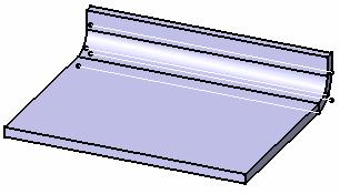
15 Page Select the sketch you just created as the support of the web. A preview of the web appears. 9. Click OK to create the web. Here is the web.
16 Page 16 You can click the Sketcher icon to edit the sketch.
17 Creating a Surfacic Flange on a Web Page 17 This section explains how to create a surfacic flange on a web, that is a feature which enables to stiffen the part. The web is still open from the previous task. 1. Click the Surfacic flange icon. The Surfacic Flange definition dialog box is displayed. 2. Choose the web as the Base Feature. 3. Choose the yz plane as support.


18 Page Click Preview to see the surfacic flange. 5. Click OK to create the surfacic flange. Here is the surfacic flange.
19 Creating a CutOut Page 19 In this task, you will learn how to: open a sketch on an existing face define a contour on the face in order to create a cutout. You can create a cutout defined either by a sketch or an open geometry. The surfacic flange is still open from the previous task. 1. Select the surface from the geometry area to define the working plane. 2. Click the Sketcher icon. 3. Click the Elongated Hole icon to create the contour. To access the oblong profile, click the black triangle on the Rectangle icon. It displays a secondary toolbar. 4. Click to create the first point and drag the cursor. 5. Click to create the second point. The first semi-axis of the profile is created. 6. Drag the cursor and click to create the third point. The second semi-axis is created and the oblong profile is displayed.

20 Page Click the CutOut icon. The CutOut Definition dialog box is displayed and a cutout is previewed with default parameters. The vectors show the side and the direction of the cutout.
21 Page Select the Dimension type to define the limit of your cutout. 9. Click Ok. Here is your cutout.

22 Extracting Drawings from the Aerospace SheetMetal Design Part Page 22 This task shows how to create the Aerospace SheetMetal Design Part views in the Generative Drafting workbench. The Sheet Metal part is displayed. 1. Click or select File -> New Select the Drawing type and click OK. The Generative Drafting workbench is launched. The New Drawing dialog box opens. 3. Click OK. For more information about this workbench, refer to Generative Drafting User's Guide. 4. The drawing sheet appears. 5. Tile the windows horizontally using the Window -> Tile Horizontally menu item. 6. Select the Unfolded View icon in the Projections toolbar from Generative Drafting Workbench.

23 Page 23 This icon is added to the Projections toolbar provided the Sheet Metal workbench is present. 7. Choose the xy plane in the Sheet Metal specification tree. The unfolded view is displayed with the bends axes and limits. Eventually, the Drafting sheet looks like this:
24 User Tasks Page 24 Managing the Default Parameters Creating a Web Creating a Surfacic Flange Creating a Joggle Creating Swept Walls Unfolding Creating a CutOut Creating a Hole Creating Stamping Features Creating a Local Corner Relief Creating Constraints Mapping Elements Creating Corners Creating Chamfers Patterning Reference Elements Displaying Characteristic Curves Looking For Aerospace SheetMetal Features Browsing the Sheetmetal Catalog Integration With Part Design
25 Managing the Default Parameters Page 25 This section explains and illustrates how to use or modify various kinds of features. The table below lists the information you will find. Using Aerospace Sheetmetal Design assumes that you are in a CATPart document. Edit the parameters: select the Parameters tab and define the element thickness and bend radius values. Compute the bend allowance: select the Bend Allowance tab and define the allowance value (K factor). Define the compensations: select the Compensations tab and define the compensations for the joggle and the sides. Please refer to the Customizing chapter to define the Sheet Standards Files.
26 Editing the Sheet and Tool Parameters This section explains how to change the different sheet metal parameters needed to create your first feature. Page Click the Sheet Metal Parameters icon. The Sheet Metal Parameters dialog box is displayed. 2. Change the Thickness if needed. 3. Change the Minimum Bend Radius if needed. The Minimum Bend radius defines the minimum internal radius allowing the creation of a bend. 4. Change the Default Bend Radius if needed. To do this, you need to deactivate the formula first by clicking the formula icon. The Default Bend Radius corresponds to the internal radius and is linked by default to the creation of the surfacic flanges. You can set the value to 0 to create bend with no radius. If using the DIN standard, the KFactor automatically sets to 0 as well. Convention dictates that the inner angle between the two elements is used to define the bend. It can vary from 0deg to 180deg exclusive. This angle is constant and the bend axis is rectilinear. 5. Click OK to validate the Sheet Metal Parameters. The Standard field displays the Standard to use with the part, if implemented. The name of this standard file is defined in a Design Table. When the Check all the bend radii button is checked, and you click OK in the Sheet Metal Parameters dialog box, existing bend radii are checked and a list displays all surfacic flanges or bends that do not use the minimum Bend Radius value as defined in step 3. Therefore, they will not be modified. Parameters can be defined in a Design Table. To do so, press the Sheet Standards Files... button to access to the company defined standards, if need be. For more information, refer to the Customizing Standard Files section. All parameters hereafter, or only some of them, can be defined in this Design Table: Sheet Metal Parameters Column associated in the Design TableDefinition Standard in Sheet Metal ParametersSheetMetalStandard sheet reference name Thickness Thickness sheet thickness Minimum Bend Radius MinimumBendRadius minimum bend radius Default Bend Radius DefaultBendRadius default bend radius K Factor KFactor neutral fiber position Radius Table RadiusTable path to the file with all available radii Whenever both Radius Table and Default Bend Radius are defined in the Design Table, only the Radius Table will be taken into account for the bend creation. Standard Names For Holes Column associated in the Design Table Definition Clearance Hole ClearanceHoleStd path to the Clearance Hole Standard file Index Hole IndexHoleStd path to the Index Hole Standard file Manufacturing Hole ManufacturingHoleStd path to the Manufacturing Hole Standard file Fastener Hole FastenerHoleStd path to the Fastener Hole Standard file


27 Page 27 Standard Names For Stamps Column associated in the Design Table Definition Flanged Hole ExtrudedHoleStd path to the Flanged Hole Standard file Bead BeadStd path to the Bead Standard file Circular Stamp CircularStampStd path to the Circular Stamp Standard file Surface Stamp SurfaceStampStd path to the Surface Stamp Standard file Flanged CutOut FlangedCutoutStd path to the Flanged CutOut Standard file Curve Stamp CurveStampStd path to the Curve Stamp Standard file When a parameter refers to a path, another sub-design Table will be associated to the corresponding feature. 1. Here is an example for the use of a bend allowance table: Main Sheet Metal Parameters Design Table Radius Table For Thickness 2 This table defines available all bend radii for a thickness of 2 mm. A design table will be created on the Default Bend Radius of the Sheet Metal Parameters and on the Radius of each bend. Bend Table for Thickness 2 and Bend Radius 1 Whenever a bend is created, a radius table will be associated. If the configuration "Bend Radius = 1mm" is selected, a new design table (the Bend Table) will be created from BendTableT2R1.xls in order to compute the bend allowance. According to the open angle, the bend deduction will be read in the Allowance column or interpolated if necessary. 2. Here is an example for the use of a hole standard file: Main Sheet Metal Parameters Design Table Hole Standard Whenever a hole is created, a design table will associate its radius with a standard name. 3. Here is an example for the use of a stamp standard file: Main Sheet Metal Parameters Design Table
28 Page 28 Whenever a stamp is created, a design table will associate its dimension with a standard name. Surface Stamp Curve Stamp Circular Stamp Bead Flanged Cutout Flanged Hole Stiffening Rib


29 Computing the Bend Allowance Page 29 This section explains the calculations related to folding/unfolding operations. 1. Click the SheetMetal Parameters icon. The Sheet Metal Parameters dialog box is displayed. The fourth tab concerns the bend allowance. Bend Allowance The bend allowance corresponds to the unfolded bend width. bend < 90deg bend > 90deg L is the total unfolded length A and B the dimensioning lengths as defined on the above figure. They are similar to the DIN definition. K Factor Physically, the neutral fiber represents the limit between the material compressed area inside the bend and the extended area outside the bend. Ideally, it is represented by an arc located inside the thickness and centered on the bend axis.
30 The K factor defines the neutral fiber position: Page 30 W = α * (R + k * T) where: W is the bend allowance R the inner bend radius T the sheet metal thickness α the inner bend angle in radians. If β is the opening bend angle in degrees: α = π * (180 - β) / 180 When you define the sheet metal parameters, a literal feature defines the default K Factor and a formula is applied to implement the DIN standard. This standard is defined for thin steel parts. Therefore the K Factor value ranges between 0 and 0.5. The DIN definition for the K factor slightly differs. W = α * (R + k' * T/2) Therefore k' = 2 * k and ranges from 0 to 1. This formula can be deactivated or modified by right-clicking in the K factor field and choosing an option from the contextual menu. It can be re-activated by clicking the Apply DIN button. Moreover, the limit values can also be modified. When a bend is created, its own K Factor literal is created. Two cases may then occur: a. If the Sheet Metal K Factor has an activated formula using the default bend radius as input parameter, the same formula is activated on the bend K Factor replacing the default bend radius by the local bend radius as input. b. In all other cases, a formula "equal to the Sheet Metal K Factor" is activated on the local bend K Factor. This formula can also be deactivated or modified. Bend Deduction When the bend is unfolded, the sheet metal deformation is thus represented by the bend deduction V, defined by the formula: L = A + B + V (refer to the previous definitions). Therefore the bend deduction is related to the K factor using the following formula: V = α * (R + k * T) - 2 * (R + T) * tan ( min(π/2,α) / 2)
31 Page 31 This formula is used by default. However, it is possible to define bend tables on the sheet metal parameters. These tables define samples: thickness, bend radius, open angle, and bend deduction. In this case, the bend deduction is located in the appropriate bend table, matching thickness, bend radius, and open angle. If no accurate open angle is found, an interpolation will be performed. When updating the bend, the bend deduction is first computed using the previously defined rules. Then the bend allowance is deduced using the following formula: W = V + 2 * (R + T) * tan ( min(π/2,α) / 2) When the bend deduction is read in the bend table, the K factor is not used.

32 Defining the Compensations Page 32 This section shows how to select the appropriate method to define compensations when flattening a flange or a flange with joggles. Compensation is a modification of the standard calculation of the unfolding process which intends to best represent the material behavior. You first need to define which method you want to apply by customizing design tables. To do so, proceed as explained in Customizing Standards Files To Define Methods for Compensations. 1. Click the SheetMetal Parameters icon. The Sheet Metal Parameters dialog box is displayed. 2. Click the Compensations tab. 3. In the Joggle combo list, select the method as defined in the SheetMetal Standard files: None: no compensation is applied Method 1 (= Method V4) Method 2 If the method you chose is not the one defined in the SheetMetal Standard Files, a warning message is issued prompting you to select another file.

33 Page 33 You can click the information icon to display a schema explaining both methods. More information is available in Customizing Standards Files To Define Methods for Compensations. 4. In the Flange Sides combo list, select how the sides will be computed: None: no compensation is applied Manual: Angle: the deformation is computed according to an angle Manual: Length: the deformation is computed according to a length 5. Click OK in the dialog box to validate the compensations parameters.
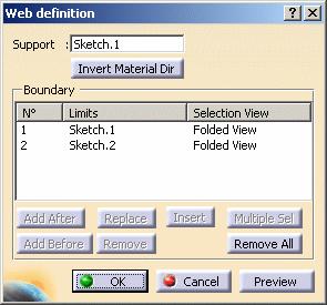
34 Creating a Web Page 34 This section explains how to create a web, that is the main feature of an Aerospace SheetMetal Design part. Open the Web1.CATPart document. 1. Click the Web icon. The Web definition dialog box is displayed. 2. In the Support field, select the support geometry in the specification tree. It can either be: a plane (example from the Web from open geometry open body). The Material Direction is displayed, perpendicular to the geometrical support. You can reverse the direction by clicking the arrow.


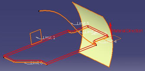
35 Page 35 a closed sketch (example from the Web from closed sketches open body). In our example, there are two closed sketches: the web will be calculated on the smallest part of the second sketch. The Material Direction is displayed, perpendicular to the geometrical support. You can reverse the direction by clicking the arrow.
 one or more sketches The elements must be selected consecutively.")
36 Page 36 You can click the Invert Material Dir button to reverse the material direction of the web. 3. In the Boundary field, in the case of an open geometry, select the elements that limit the support geometry. It can either be: a list of elements (curves, surfaces, or planes) one or more sketches The elements must be selected consecutively. They are displayed in the Boundary frame, in the order you have just chosen them, as well as in the 3D geometry.
37 Page 37
 add a limit before the selected limit (Add Before)")
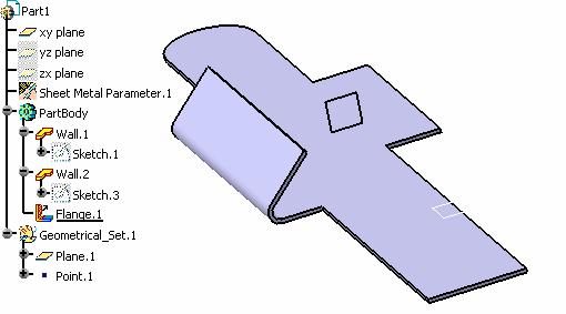
38 Page 38 When a closed profile can be built, a light preview of the web is available. Otherwise, click Preview. You can modify the selection by selecting an existing limit and using the following buttons to: add a limit after the selected limit (Add After) add a limit before the selected limit (Add Before) replace a limit (Replace) remove a limit (Remove) select a limit more than one time (Insert) select several limits to modify the existing limit (Multiple Sel). This option is available once you have selected Add After: the Limits to Add dialog box appears to let you select the limits. remove all limits (Remove All) Once you have modified the selection, a light preview is available. You can click the Preview button to display the result of the web. When the contour is defined by a list of geometrical elements, the following operations are performed: the curves are projected on the web geometrical support the surfaces are intersected with the web geometrical support 4. Click OK. The web (identified as Web.xxx) is created and the specification tree is updated accordingly.
. Sketch.")
39 Page 39 Features are aggregated under the web (identified as Web.xxx) so that they can be selected for a later use. The sketches are aggregated under the web (identified as Web.xxx). Sketch.1 is displayed in No Show mode as it was only used to create the web.
40 Creating a Surfacic Flange Page 40 This section explains how to create a surfacic flange on a web, or an existing surfacic flange (in that case, their fillets must not intersect). Open the SurfacicFlange1.CATPart document. Create a web as shown in the previous task. Here are the different elements taken into account when creating a surfacic flange: Base Feature Support EOP Sides and Corners Process Compensations 1. Click the Surfacic Flange icon. The Surfacic Flange definition dialog box is displayed.

41 Page 41 Base Feature In the Base Feature tab, the Bend Radius is of Constant type. It is set to the default bend radius of the part. 2. You can modify the fillet Radius value by changing the driving equation: click the icon. The Formula Editor dialog box opens, you can modify the dictionary and the parameters. Or you may need to deactivate the formula using the contextual menu on the field and choosing Formula -> Deactivate before editing the value. 3. Choose the web as the Base Feature. Once you chose the base feature, the Support tab automatically displays. Support 4. In the Support tab, choose the surfacic flange's geometrical support. It can either be a surface, a plane or a curve. Make sure the support is big enough to be able to later define an EOP with a length from OML. The OML is a curve created by intersecting the flange support and a plane perpendicular to the web and normal to the OML.
, computed at the intersection between the support surface and the web plane.")
42 Page 42 Exact: the selected support is to be used for the creation of the surfacic flange. Approximation: the support surface is approximated using a ruled surface. This ruled surface is defined from two curves: the OML (in light blue), computed at the intersection between the support surface and the web plane. a curve parallel to the OML (in pink), computed at a distance equal to the approximation length This mode enables you to compute the maximum deviation between the support geometry and the approximated surface. Angle: the support of the surfacic flange can also be defined by a line, a curve, an angle or the edge of a base feature. The angle is constant and you can change its value using the spinners. You can modify the Support Length generated by the curve and the angle. By default, the length is set to ten times the EOP (Edge of Part) length. If the default EOP length is higher than 100mm, you need to modify the surface length.
43 Page 43 The red angle is the angle taken into account when creating the surfacic flange. 5. Define the vectors' directions. The vectors show the Base Feature Direction, the Direction and the Material Direction according to the direction of the geometrical support of the surfacic flange. You can modify the directions by clicking the arrows. The surfaces (or curves) used to define the support surface must be continuous in point and tangency.
 tab, you can define either: a length from OML (Outer Mold Line): length between the curve defining the top of the surfacic flange and the OML, an element FD (Folded):")
44 Page 44 EOP 6. In the EOP (Edge Of Part) tab, you can define either: a length from OML (Outer Mold Line): length between the curve defining the top of the surfacic flange and the OML, an element FD (Folded): boundary element (either a surface that intersects with its surface, or a sketch, or a wire projected on its surface), an element FP (Flat Pattern): curve or sketch defining the flattened contour of the surfacic flange. The element FP must be included within the limits of the surfacic flange support when folded. 7. Click OK. The Surfacic Flange (identified as Surfacic Flange.xxx) is created and the specification tree is updated accordingly.
45 Page 45 Surfacic Flange with a length from OML of 15 mm Surfacic Flange with Plane.2 (in pink) as Element FD

46 Page 46 Surfacic Flange with EOP FP (in light blue) as Element FP Unfolded view of the Surfacic Flange with EOP FP as Element FP. See Unfolding.
 none: no")
: curve defining the flattened contour of the flange.")
47 Page 47 Sides and Corners In the Sides and Corners tab, you can choose to define the following elements: sides (intersection between the Base Feature and a curve) as: standard: they are automatically defined at the web limit and the perpendicular plans are kept (in this case, the user does not have to define them) none: no side computed (only the EOP will define the contour of the Flange) element FD (Folded): they are defined by a folded geometrical element (curve, plane or surface). element FP (Flat Pattern): curve defining the flattened contour of the flange. Surfacic Flange defined with a Length from OML of 10mm, and Side 1 and 2 as Standard
48 Page 48 Surfacic Flange defined with EOP FD as Element FD, and Side 1 and 2 as None Folded view of the Surfacic Flange with EOP FP as Element FP, Side 1 FP and Side 2 FP (in light brown) as Side 1 and Side 2. See Unfolding.

49 Page 49 Unfolded view of the Surfacic Flange with EOP FP as Element FP, Side 1 FP and Side 2 FP (in light brown) as Side 1 and Side 2. See Unfolding. a. The following examples show two cases of a flange defined by an EOP FP or FD and Sides as None. There is an intersection between the EOP and the web support -> the Surfacic Flange can be computed

50 Page 50 There is no intersection between the EOP and the web support -> the Surfacic Flange cannot be computed b. The following examples show two cases of a flange defined by an element FD as the EOP and Standard sides. There is an intersection between the EOP and the side -> the Surfacic Flange can be computed

51 Page 51 There is no intersection between the EOP and the side -> the Surfacic Flange cannot be computed c. The following examples show two cases of a flange defined by an element FP as the EOP and Standard sides. There is an intersection between the OML and the EOP -> the Surfacic Flange can be computed

52 Page 52 There is no intersection between the OML and the EOP -> the Surfacic Flange cannot be computed d. The following examples show three cases of a flange defined by an element FD as the side. There is an intersection between the Element FD and the OML and between the side and the EOP -> the Surfacic Flange can be computed


53 Page 53 There is an intersection between the side and the OML but no intersection between the side and the EOP -> the Surfacic Flange cannot be computed There is an intersection between the side and the EOP but no intersection between the side and the OML - > the Surfacic Flange cannot be computed e. The following examples show three cases of a flange defined by an element FD as the side.
54 Page 54 There is an intersection between the side and the EOP and between the side and the OML - > the Surfacic Flange can be computed There is an intersection between the side and the OML but no intersection between the side and the EOP -> the Surfacic Flange cannot be computed

55 Page 55 There is an intersection between the side and the EOP but no intersection between the side and the OML - > the Surfacic Flange cannot be computed Standard sides are calculated on the first profile of a web that did not undergo any modifications. Any modification on the web will not be taken into account to create the surfacic flange's sides. For example, if you create a cutout on the web, then create a surfacic flange with standard sides, the latter will be calculated from the web's profile without the cutout (please note that the cutout's role is not to redefine the web) For optimization reasons, we advise you to first create a sketch with the desired shape, then create the surfacic flange. The example above shows a Surfacic Flange with standard sides calculated from the web modified by a cutout (the cutout, shown in blue, is ignored)
 corners (profile defined between the EOP and the sides) as: none: no corner computed (only the")
 The example above shows a Surfacic Flange defined with Sides 1 and 2 as Standard, and Corners 1 and 2 of 10mm")
56 Page 56 The example above shows a Surfacic Flange with standard sides calculated from the web defined entirely by a sketch (shown in blue) corners (profile defined between the EOP and the sides) as: none: no corner computed (only the EOP is able to define the contour of the Surfacic Flange) corner: between the side and the EOP (defined with a radius value) The example above shows a Surfacic Flange defined with Sides 1 and 2 as Standard, and Corners 1 and 2 of 10mm each.

57 Page 57 In the case the user does not define a surfacic flange side, the latter is automatically computed at the Web limit, perpendicular to the OML. In the case no corner is defined, the side and the EOP are simply relimiting each other. The sides of the fillet are continuous in tangency with the contour of the web and the sides of the surfacic flange. Process In the Process tab, you can define the: Manufacturing process: Hydropressed BreakFormed K_Factor: you can modify the K Factor as defined in the SheetMetal Parameters dialog box by changing the driving equation. Click the icon. The Formula Editor dialog box opens, you can modify the dictionary and the parameters. Or you may need to deactivate the formula using the contextual menu on the field and choosing Formula -> Deactivate before editing the value. You can also choose to display the characteristic curves either on the folded view (Show curves in folded views), and/or on the flattened view (Show curves in flattened view) of the part.

58 Page 58 Compensations In the Compensations tab, you can define compensations for the: Joggle: check the Apply Compensation button when creating or editing the joggle. See Creating a Joggle for further information. Standard files and methods must be previously defined from the SheetMetal Parameters dialog box to have access to the Apply Compensation button. Surfacic Flange Sides (Side 1 and Side 2). Define the type: None: no compensation is applied Manual: Angle: the deformation is computed according to an angle Manual: Length: the deformation is computed according to a length parallel to the BTL. Define the Angle in the case of a Manual: Angle compensation. A negative angle adds material, and a positive angle removes material. Define the Length in the case of a Manual: Length compensation
59 Page 59 The values of the modification are the angles A1 and A2.
 shows that material will be added to the sides.")
60 Page 60 Compensations can be created either on the folded or flattened part, but they only apply on the flattened part. Compensations can be modified independently on each flange. The + sign (in yellow in the 3D geometry) shows that material will be added to the sides. Unfolded Surfacic Flange defined with Corners 1 and 2 of 10mm each, and no compensation for Side 1 and Side 2

61 Page 61 Unfolded Surfacic Flange defined with Corners 1 and 2 of 10mm each, a Manual: Angle compensation of - 20deg for Side 1 and no compensation for Side 2 Unfolded Surfacic Flange defined with Corners 1 and 2 of 10mm each, a Manual: Angle compensation of 20deg for Side 1 and - 10deg for Side 2

62 Creating a Joggle Page 62 This task explains how to create a joggle, that is a feature which causes the surfacic flange to be locally deformed. The joggle is a feature which cannot exist alone, it is always defined on a surfacic flange. Open the Joggle1.CATPart document. Create a surfacic flange as shown in the previous task. 1. Click the Joggle icon. 2. Select the surfacic flange as the support. The Support of the joggle is not automatically set to the last created surfacic flange. 3. Choose a plane as the joggle plane, here we choose Plane3. The blue curve defines the boundary of the web. The vectors show you the joggle directions: - The vector on the surfacic flange support determines the depth direction - The vector on the joggle plane determines the side on which the joggle is to be created In case there are several intersections between the surfacic flange and the plane, the closest intersection is chosen.
 The dotted lines must remain inside the blue curve.")

63 Page 63 You can click the the joggle parameters to be defined. icon to display a schema showing 4. You can modify the following parameters of the joggle by clicking the up and down arrows. depth: offset from the support surface (shown as dotted lines) The dotted lines must remain inside the blue curve. runout: length of the offset, between the original surface of the surfacic flange and the new surface (joggle) clearance: length added to the offset at the joggle starting plane start radius: fillet between the runout and the surfacic flange end radius: fillet between the runout and the offset 5. Click OK. The joggle (identified as Joggle.xxx) is created and the specification tree is updated accordingly. If you modify the depth, the runout adjusts automatically. You can reverse the runout direction either by clicking the red arrow or by clicking the Invert Runout Dir button in the dialog box. You can reverse the depth direction either by clicking the red arrow or by clicking the Invert Depth Dir button in the dialog box. Applying Compensations You can apply compensations when creating the surfacic flange or editing the joggle. Compensations can be created either on the folded or flattened part, but they only apply on the flattened part. Open the Joggle2.CATPart document for a single joggle, Joggle.3CATPart for a twin joggle, and Joggle4.CATPart for a double joggle. Standard Files must have been previously imported and a method for compensations defined.

64 Page Double-click the surfacic flange supporting the joggle to edit it. 2. In the Compensations tab, click the Apply Compensations button. On a single joggle Unfolded single joggle without compensations Unfolded single joggle with compensations relying on Method 1 Unfolded single joggle with compensations relying on Method 2


65 Page 65 On a twin joggle Unfolded twin joggle without compensations Unfolded twin joggle with compensations relying on Method 1 Unfolded twin joggle with compensations relying on Method 2 On a double joggle Unfolded double joggle without compensations
66 Page 66 Unfolded double joggle with compensations relying on Method 1 Unfolded double joggle with compensations relying on Method 2


67 Creating Swept Walls Page 67 This section explains and illustrates how to create and use various kinds of swept walls, i.e. walls based on a given contour that is swept along a spine. Create a flange: select a spine, and set the radius, length, and angle values. Create a hem: select a spine, and set the radius, and length values. Create a tear drop: select a spine, and set the radius, and length values. Create a swept flange: select a spine, and a user-defined profile Selecting the Spine Whatever the type of the swept wall you wish to create, you first need to select one or more contiguous edges to make up the spine along which the contour, either pre- or user-defined, is to be swept. You can: manually select one, or more, edge(s) Selection without propagation Resulting flange without propagation select one edge and click the Tangency Propagation button: all contiguous and tangent edges are selected. In this case, would you need to remove one edge, you need to manually select it. Remember that only extremity edges can be removed without breaking the continuity between edges.


68 Page 68 Selection with propagation Resulting flange with propagation

69 Creating a Flange Page 69 This task explains how to generate a flange from a spine and a profile. For the Generative Sheetmetal Design workbench, open the NEWSweptWall01.CATPart document. For the Aerospace SheetMetal Design workbench, open the Aero_SweptWall01.CATPart document. 1. Select the Flange icon in the Swept Walls sub-toolbar. The Flange Definition dialog box is displayed. Note that the image in the right-hand pane of the dialog box is updated as you choose your parameters and options, and provides a graphical explanation about the current selection. By default, the icon which is pre-selected next to the Angle field corresponds to an acute angle for the Generative Sheetmetal Design workbench, and to an obtuse angle for the Aerospace SheetMetal Design workbench. 2. Select the edge as shown in red.
70 Page 70 The Spine field is updated with the selected edge. You can use the Remove All button to remove the selected edge(s). You can use the Propagate button to select all tangentially contiguous edges forming the spine. The drop-down list offers two choices: Basic: the flange is created along the whole support. Relimited: the flange is created within limits you define on the support (points, for example). 3. Leave Basic selected. Selecting Relimited updates the dialog with two new fields (Limit 1 and Limit 2) to let you specify the flange limits. You can then select as the limits two points, two planar faces, a point and a planar face, or a point and a vertex, as shown below, for example. Note that right-clicking in the Limit 1 and Limit 2 fields lets you create the limits (points, plane) or choose the X, Y or Z plane on-the-fly.

71 Page Choose the flange parameters: Enter 15mm in the Length field. Use the icons next to the field to specify the type of length. Note that the length is always computed using the lowest external point of the flange. Enter 45deg in the Angle field. Use the icons next to the field to specify whether the angle is acute or obtuse. Enter 2mm in the Radius field. 5. Check the Trim Support option to trim the selected edge. The Trim Support option only works in the case of a planar support. You cannot select Relimited and Trim Support at once. Indeed, lateral cuts in the sheet metal part are currently not supported when the support is trimmed (i.e. the flange must be created from one edge of the sheet metal part to the other). 6. Click the Reverse Direction button to reverse the direction of the flange. 7. Click the Invert Material Side button to invert the material side. (This option is only available when the Trim Support option is checked, otherwise it is deactivated.) 8. Click the More button to display the Bend Allowance tab allowing you to locally redefine the bend allowance settings. You may need to deactivate the formula using the contextual menu on the field and choosing Formula -> Deactivate before editing the value.


72 Page 72 In this case, the new K Factor value overrides the value set in the Sheet Metal Parameters. A preview of the flange to be created is displayed in the geometry area. 9. When you are satisfied with the result, click OK to create the flange. The flange is created and the feature is added to the specification tree.
73 Page 73

74 Creating a Hem Page 74 This task explains how to generate a hem from a spine and a profile. The NEWSweptWall01.CATPart document is still open from the previous task. If not, open the NEWSweptWall02.CATPart document from the samples directory. 1. Select the Hem icon in the Swept Walls subtoolbar. The Hem Definition dialog box opens. Note that the image in the right-hand pane of the dialog box is updated as you choose your parameters and options, and provides a graphical explanation about the current selection. 2. Select the edge as shown.
75 Page 75 The Spine field is updated with the selected edge. You can use the Remove All button to remove the selected edge(s). You can use the Propagate button to select all tangentially contiguous edges forming the spine. The drop-down list offers two choices: Basic: the hem is created along the whole support. Relimited: the hem is created within limits you define on the support (points, for example). 3. Leave Basic selected. Selecting Relimited updates the dialog with two new fields (Limit 1 and Limit 2) to let you specify the hem limits. You can then select as the limits two points, two planar faces, a point and a planar face, or a point and a vertex, for example. Note that right-clicking in the Limit 1 and Limit 2 fields lets you create the limits (points, plane) or choose the X, Y or Z plane on-the-fly. 4. Enter 3mm in the Length field, and 2mm in the Radius field. 5. Check the Trim Support option to trim the selected edge. The Trim Support option only works in the case of a planar support.

76 Page 76 You cannot select Relimited and Trim Support at once. Indeed, lateral cuts in the sheet metal part are currently not supported when the support is trimmed (i.e. the hem must be created from one edge of the sheet metal part to the other). 6. Click the Reverse Direction button to reverse the direction of the hem. 7. Click the More button to display the Bend Allowance tab allowing you to locally redefine the bend allowance settings. You may need to deactivate the formula using the contextual menu on the field and choosing Formula -> Deactivate before editing the value. In this case, the new K Factor value overrides the value set in the Sheet Metal Parameters. A preview of the hem to be created is displayed in the geometry area.

77 Page When you are satisfied with the result, click OK to create the hem. The hem is created and the feature is added to the specification tree.
78 Creating a Tear Drop Page 78 This task explains how to generate a tear drop from a spine and a profile. The NEWSweptWall01.CATPart document is still open from the previous task. If not, open the NEWSweptWall03.CATPart document from the samples directory. 1. Select the Tear Drop icon in the Swept Walls sub-toolbar. The Tear Drop Definition dialog box opens. Note that the image in the right-hand pane of the dialog box is updated as you choose your parameters and options, and provides a graphical explanation about the current selection. 2. Select the edge as shown in red.

79 Page 79 The Spine field is updated with the selected edge. You can use the Remove All button to remove the selected edge(s). You can use the Propagate button to select all tangentially contiguous edges forming the spine. The drop-down list offers two choices: Basic: the tear drop is created along the whole support. Relimited: the tear drop is created within limits you define on the support (points, for example). 3. Leave Basic selected. Selecting Relimited updates the dialog with two new fields (Limit 1 and Limit 2) to let you specify the tear drop limits. You can then select as the limits two points, two planar faces, a point and a planar face, or a point and a vertex, for example. Note that right-clicking in the Limit 1 and Limit 2 fields lets you create the limits (points, plane) or choose the X, Y or Z plane on-the-fly. 4. Enter 8mm in the Length field, and 3mm in the Radius field. 5. Check the Trim Support option to trim the selected edge. The Trim Support option only works in the case of a planar support.
80 Page 80 You cannot select Relimited and Trim Support at once. Indeed, lateral cuts in the sheet metal part are currently not supported when the support is trimmed (i.e. the tear drop must be created from one edge of the sheet metal part to the other). 6. Click the Reverse Direction button to reverse the direction of the tear drop. 7. Click the More>> button to display the Bend Allowance tab allowing you to locally redefine the bend allowance settings. You may need to deactivate the formula using the contextual menu on the field and choosing Formula -> Deactivate before editing the value. In this case, the new K Factor value overrides the value set in the Sheet Metal Parameters. A preview of the tear drop to be created is displayed in the geometry area.

81 Page When you are satisfied with the result, click OK to create the tear drop. The tear drop is created and the feature is added to the specification tree.


82 Creating a User Flange Page 82 This task explains how to generate a user flange from a spine and a user-defined profile. The NEWSweptWall01.CATPart document is still open from the previous task. If not, open the NEWSweptWall04.CATPart document from the samples directory. 1. Select the User Flange icon in the Swept Walls subtoolbar. The User Defined Flange Definition dialog box opens. 2. Using the Sketcher icon, define a profile in the yz plane as shown below: Then quit the Sketcher, using the Exit icon. 3. Select the edge and the profile, as shown in red.
83 Page 83 The dialog box looks like this: 4. Click the More button to display the Bend Allowance tab allowing you to locally redefine the bend allowance settings. You may need to deactivate the formula using the contextual menu on the field and choosing Formula -> Deactivate before editing the value.


84 Page 84 In this case, the new K Factor value overrides the value set in the Sheet Metal Parameters. 5. Click OK to create the user flange. The feature is added in the specification tree.
85 Page 85 Use the Remove All button to remove the selected edge(s). Use the Propagate button to select all tangentially contiguous edges forming the spine.
86 Unfolding Page 86 Unfolded Aerospace Sheet Metal parts can be displayed in two ways: Folded/Unfolded View Access Concurrent Access Each Aerospace Sheet Metal feature is created in a given view: folded, or unfolded. Editing a feature must be done in its definition view. If not, a message is automatically issued, prompting you to change views, before editing the feature.

87 Folded/Unfolded View Access Page 87 This task shows how to unfold the part. 1. Click the Unfold icon. The part is unfolded according to the reference wall plane or web, as shown below. 2. Click this icon again to refold the part for the next task. In Sheetmetal Design, bend limits and stamping are now displayed in the unfolded view. However, cutouts created on stamps are not. When designing in context, if a CATProduct document contains several Sheetmetal parts, only one part can be visualized in the unfolded view at a time.
88 Concurrent Access Page 88 This functionality is P2 for Sheetmetal Design. This task explains how to display the Sheet Metal part in two windows: one with the folded view, one with the unfolded view. Any modification in one window. is displayed in the other window. 1. Click the Multi-view icon The part is unfolded in a second window. 2. Choose the Window -> Tile Horizontally menu item. Both windows are tiled. Activate the window in which you want to work.
89 Page 89 Any modification in one view is taken into account in the other view enabling the user to make modifications in the best possible context. In the multi-view mode as in the standard unfolded view, all constraints are displayed in the geometrical views. Once in the Multi-view mode, the standard icon Unfold is not longer available. The Multi-view function is not available from a standard unfolded view. Only parts with bends can be unfolded. Cutting faces and open faces are not displayed in Multi-view mode (Sheetmetal Design)
90 Creating a Cutout Page 90 This task explains how to create a cutout. Creating a cutout consists in extruding a profile and removing the material resulting from the extrusion. You can create a cutout defined either by a sketch or an open geometry. Open the CutOut1.CATPart document. 1. Click the CutOut icon. 2. Select a profile. The CutOut Definition dialog box is displayed and a cutout is previewed with default parameters. The vectors show the side and the direction of the cutout.
91 Page 91 Once the sketch is selected, you can modify it by clicking the Sketcher icon. 3. Select the type. Several limit types are available: Dimension: the cutout depth is defined by the value measured along the direction. The depth corresponds to the web thickness. Please refer to Editing the Sheet and Tool Parameters. Up to next: the limit is the first face the application detects while extruding the profile. This face must stops the whole extrusion, not only a portion of it, and the hole goes through material. Up to last: the application will limit the cutout onto the last possible face encountered by the extrusion. 9. Select the profile you created using the sketcher (here Sketch.2). It can be either a sketch containing one or more shapes, a wire, or a part. The Reverse Side option lets you choose between removing the material defined within the profile, which is the application's default behavior, or the material surrounding the profile. The Reverse Direction option allows you to invert the direction of the extrusion pointed by the arrow.
 is created and the specification tree is updated accordingly. 11.")
.")
92 Page Click OK. The cutout (identified as Cutout.xxx) is created and the specification tree is updated accordingly. 11. Click More>> to display the maximum information. The Direction is already selected (Sketch.2). If not, it must be perpendicular to the web. 12. Select the Support (here we chose the web).
93 Page 93 Once the Reference Direction and the Objects Support fields are filled in, the selection can be modified but cannot be cleared. Cutouts can be created directly on the unfolded view of the part. You can use the Catalog icon to open the Catalog Browser. May you want to create a cutout on an overlapping element or a bend with radius=0, either choose the top skin of the element (as shown in the picture above), or unfold the part to create the cutout. Refer to Component Catalog Editor documentation to have further information on how to use catalogs. Refer to the Create a Pocket task in the Part Design User's Guide for further details on how to create cutouts.

94 Creating a Hole Page 94 This task shows you how to create a hole, that consists in removing material from a body. Open the Hole1.CATPart document. 1. Click the Hole icon. The Hole definition dialog box opens. 2. Select the Point that will be the center of the hole. It can be either a sketch containing one or more points, or a point, or several points. The point can be selected anywhere in the geometry, not necessarily on a surface. In that case, an orthogonal projection will be performed. You can also directly click the surface: a point will be created under the pointer. To deselect a point, click it in the specification tree. 3. Select the Support object where the hole will be positioned. The support can be different from the support where the point lies. In that case, an orthogonal projection will be performed.
95 The hole is previewed with default parameters. Page Select hole type: Clearance: defined with a center (point) and a radius Index: used to measure and validate parts Manufacturing: used for manufacturing (for example to fasten a part on an equiment Fastener: used as a rivet Hole types do not affect the hole geometry. 5. Define the value for the diameter of the hole in the Diameter field. If you change the Radius value using the spinners, the preview of the hole automatically updates. However, if you enter a value directly in the field, you need to click the Apply button to update the preview. 6. Click OK to validate. The hole (identified as Hole.xxx) is created and the specification tree is updated accordingly.

96 Page 96 To have further information on Standard Files..., please refer to the Customizing section. Holes can be created on the flattened part and on the bend in case of a flange.
97 Creating Stamping Features Page 97 This section explains and illustrates how to create and use various kinds of stamps. The table below lists the information you will find. Create a flanged hole: select a point on a face, and set the stamping parameters. Create a bead: select a profile, and set the stamping parameters. Create a circular stamp: select a point on a face, and set the stamping parameters. Create a surface stamp: select a sketch, and set the stamping parameters. Create a flanged cutout: select a profile, and set the stamping parameters. Create a stiffening rib: select the external surface of the bend, and set the stamping parameters. Create a curve stamp: select a sketch, and set the stamping parameters.
98 Creating a Flanged Hole Page 98 This task shows you how to create a flanged hole by specifying the punch geometrical parameters. For the Generative Sheetmetal Design workbench, open the NEWStamping.CATPart document. For the Aerospace SheetMetal Design workbench, open the Aero_Stamping.CATPart document. 1. Click the Flanged Hole icon. 2. Click the surface where you want to place the hole. A grid is displayed to help you position the flanged hole. The Flanged Hole Definition dialog box is displayed, providing default values.

99 Page 99 Note that the image in the right-hand pane of the dialog box is updated as you choose your parameters and options, and provides a graphical explanation about the current selection. Also note that the options available in the dialog box are updated according to the items selected in the Definition Type area. 3. Choose the diameter that should be dimensioned from the Parameters choice list: Major Diameter Minor Diameter Two Diameters (major and minor diameters) Punch & Die 4. Specify whether the flanged hole should be created without a cone (i.e. only with the filleted portion of the flanged hole) or with a cone (i.e. with the filleted portion of the flanged hole and with a cone).
100 Page 100 Note that selecting the Without cone option disables the Height H field, as the height is automatically computed in this case. 5. If you want to use a standard, click the Standard File button and browse to select a standard file. In this case, the standard parameters will be used, and you do not need to specify the flanged hole parameters. You can skip the next step. 6. Choose the flanged hole parameters: In the Height H field, specify the height value for the flanged hole. Use the icon next to the field to specify the reference from which the height is defined: or. In the Radius R field, specify the radius value for the flanged hole external curvature. Use the icon next to the field to disable this option. In the Angle A field, specify the angle value for the flanged hole. This option is not available for the Two Diameters or Punch & Die parameters, as the angle is automatically computed in these cases. In the Diameter D field, specify the major diameter value for the flanged hole. This option is not available for the Minor Diameter parameter, as the major diameter is automatically computed in this case. In the Diameter d field, specify the minor diameter value for the flanged hole. This option is not available for the Major Diameter parameter, as the minor diameter is automatically computed in this case.
 is created and the specification tree is updated accordingly.")
101 Page Click Preview to preview the flanged hole. 8. Click OK to validate. The flanged hole (identified as Flanged Hole.xxx) is created and the specification tree is updated accordingly. Flanged hole viewed from the front

102 Page 102 Flanged hole viewed from the back Refer to the Customizing Standard Files chapter for more information about defining the Standards Files.

103 Creating a Bead Page 103 This task shows you how to create a bead, that is a local deformation in the web. Open the NEWStamping6.CATPart document. If you use the Aerospace SheetMetal Design workbench, open the Aero_Stamping6.CATPart document. 1. Click the Bead icon. 2. Select the spine profile where you want to place the bead. The Bead definition dialog box is displayed, providing default values. 3. Change the value in the different fields, if needed: Height H Radius R Section Radius R1 (corresponding to the cross section value) End Radius R2 The Sketch is automatically set to the sketch you chose.
 is created and the specification tree is updated accordingly. The vector cannot be reverted until the bead spine is defined.")
104 Page 104 The vector for the direction of the bead is shown in the model and a preview of the bead appears and a vector shows its direction. 4. Click Apply to preview the bead. 5. Click OK to validate. The bead (identified as Bead.xxx) is created and the specification tree is updated accordingly. The vector cannot be reverted until the bead spine is defined. You can use 0 as the Radius value to deactivate the Radius R value, and to create the bead without a fillet. Please refer to the Customizing Standard Files chapter to define the Standards Files.


105 Creating a Circular Stamp Page 105 This task shows you how to create a point stamp by specifying the punch geometrical parameters. Open the NEWStamping.CATPart document from the samples directory. If you use the Aerospace SheetMetal Design workbench, open the Aero_Stamping.CATPart document. 1. Click the Circular Stamp icon. 2. Select a point on the top face. A grid is displayed to help you position the circular stamp. The Circular Stamp Definition dialog box opens, providing default values. 3. Change the value in the different fields, if needed: Height H Radius R1 Radius R2 Angle A Diameter D 4. Click Apply to preview the circular stamp. 5. Click OK to validate. The circular stamp (identified as Circular Stamp.xxx) is created and the specification tree is updated accordingly.


106 Page 106 You can use 0 as the Radius value to deactivate the Radius R and Radius R2 values, and to create the point stamp without a fillet. Please refer to the Customizing Standard Files chapter to define the Standards Files.


107 Creating a Surface Stamp Page 107 This task shows you how to create a surface stamp by specifying the punch geometrical parameters. Open the NEWStamping4.CATPart document from the samples directory. If you use the Aerospace SheetMetal Design workbench, open the Aero_Stamping4.CATPart document. 1. Click the Surface Stamp icon. 2. Select Sketch-for-Surface-Stamp, the profile previously defined. The Surface Stamp Definition dialog box opens, providing default values. 3. Change the value in the different fields, if needed: Height H Radius R1 Radius R2 Angle A 4. Click Apply to preview the surface stamp. 5. Click OK to validate. The surface stamp (identified as Surface Stamp.xxx) is created and the specification tree is updated accordingly.


108 Page 108 You can use 0 as the Radius value to deactivate the Radius R1 value, and to create the surface stamp without a fillet. Please refer to the Customizing Standard Files chapter to define the Standards Files.
109 Creating a Flanged Cutout Page 109 This task shows you how to create a flanged cutout by specifying the punch geometrical parameters. Open the NEWStamping8.CATPart document. If you use the Aerospace SheetMetal Design workbench, open the Aero_Stamping8.CATPart document. 1. Click the Flanged Cutout icon. 2. Select a profile. The Flanged Cutout Definition dialog box is displayed, providing default values. 3. Change the value in the different fields, if needed: Height H Radius R Angle A 4. Click Apply to preview the flanged cutout. 5. Click OK to validate. The flanged cutout (identified as Flanged Cutout.xxx) is created and the specification tree is updated accordingly.


110 Page 110 You can use 0 as the Radius value to deactivate the Radius R value, and to create the flanged cutout without a fillet. Please refer to the Customizing Standard Files chapter to define the Standards Files.

111 Creating a Stiffening Rib Page 111 This task shows you how to create a stiffness rib by specifying the punch geometrical parameters. Open the NEWStamping7.CATPart document from the samples directory. If you use the Aerospace SheetMetal Design workbench, open the Aero_Stamping7.CATPart document. 1. Click the Stiffness Rib icon. 2. Select the external surface of Bend.1, where you want to place a stiffener. Note that the stiffener will always be centered on the bend radius, wherever the point may be along the curve. A grid is displayed. The Stiffening Rib Definition dialog box opens, providing default values. 3. Change the value in the different fields, if needed: Length L Radius R1 Radius R2 Angle A 4. Click Apply to preview the stiffness rib. 5. Click OK to validate. The stiffening rib (identified as Stiffnening Rib.xxx) is created and the specification tree is updated accordingly.


112 Page 112 You can use 0 as the Radius value to deactivate the Radius R1 value, and to create the stiffening rib without a fillet. Please refer to the Customizing Standard Files chapter to define the Standards Files.


113 Creating a Curve Stamp Page 113 This task shows you how to create a curve stamp by specifying the punch geometrical parameters. Open the NEWStamping3.CATPart document. If you use the Aerospace SheetMetal Design workbench, open the Aero_Stamping3.CATPart document. 1. Click the Curve Stamp icon. 2. Select Sketch-for-Curve-Stamp, the curve previously defined. The Curve Stamp Definition dialog box opens, providing default values. 3. Change the value in the different fields, if needed: Height H: the total height Radius R1: the outer bend radius Radius R2: the inner bend radius Angle A: the stamping draft angle Length L: the stamps' maximum width 4. Click Apply to preview the curve stamp.
 is created and the specification tree is updated accordingly.")

114 Page Click OK to validate. The curve stamp (identified as Curve Stamp.xxx) is created and the specification tree is updated accordingly. You can use 0 as the Radius value to deactivate the Radius R and Radius R2 values, and to create the curve stamp without a fillet. Check the Obround option to round off the edges of the curve stamp. Obround option checked Obround option unchecked Please refer to the Customizing Standard Files chapter to define the Standards Files.

 A notch was defined on the web profile between the two fillets' flanges; so that flanges do not intersect.")
115 Creating a Local Corner Relief Page 115 This task explains how to define a corner relief locally on a set of supports. Open the NEWCornerRelief01.CATPart document from the samples directory. The part needs to be unfolded prior to creating the corner relief. 1. Click the Corner Relief icon. The Corner Relief Definition dialog box is displayed. 2. Select the supports on which a corner relief should be created (here we chose Flange.1 and Flange.2) A notch was defined on the web profile between the two fillets' flanges; so that flanges do not intersect. This operation enables to prepare the web as to create the flanges that will be later used to define the corner relief. By default the User Profile is active in the Corner Relief Definition dialog box.


116 Page Select the sketch, directly in the 3D geometry. As soon as the sketch has been selected, the Sketcher icon is displayed in the dialog box allowing you to edit the selected sketch, if needed. The red arrow lets you choose the direction of matter to remove. Click it to reverse the direction. 2. Click OK in the Corner Relief Definition dialog box. You can use the Catalog icon to open the Catalog Browser. For more information on catalogs, please refer to the Using Catalogs chapter in the CATIA Infrastructure User Guide. Select the Circular Profile using the down arrow.


117 Page Define the default radius: it is equal to the bend radius + the thickness. In our example, we defined a radius of 15 mm. By default the corner relief center is located at the intersection of the bend axes. You can select a point as the circle's center. 2. Select the vertex between the two flanges: it will be the center of the corner relief. 3. Click OK in the Corner Relief Definition dialog box. The created element (identified as Corner Relief.xxx) is added to the specification tree. 3. Fold the part to check the corner relief in 3D.


118 Page 118 Folded user corner relief Folded circular corner relief The Supports Redefinition button enables to redefine the supports' sides thus adding matter to these supports. In that case, the created element (identified as Corner Relief.xxx) appears before the supports in the specification tree. Please note that checking this button means that the corner relief replaces the flange's side. This side must therefore exists: when creating the flange, do not define the side as None.


119 Page 119 Unfolded user corner relief with redefined supports Folded user corner relief with redefined supports The image besides shows two flanges creating with Angle as support type. The two blue dotted lines represent the limits of the unfolded flanges. The creation of a corner relief with supports redefined will not be created as it is not be located within the limits of the unfolded flanges.

120 Creating Constraints Page 120 This task shows how to set geometric constraints on geometric elements. Such a constraint forces a limitation. For example, a geometric constraint might require that two lines be parallel. To set a constraint between elements: 1. Multi-select two or three elements to be constrained. 2. Click the Constraint defined in dialog box icon. The Constraint Definition dialog box appears indicating the types of constraint you can set between the selected elements. 3. Select one of the available options to specify that the corresponding constraint should be made. 4. Click OK. The corresponding constraint symbol appears on the geometry.

121 To set a constraint on a single element: Page Select the element to be constrained. 2. Click the Constraint icon. The corresponding constraint symbol appears on the geometry.

. If you use SheetMetal Design, open the Mapping1.CATPart document. If you use Generative Sheetmetal Design, open the NEWMapping1.")
122 Mapping Elements Page 122 This task shows how to create curves or points from a sketch (as designed using the Sketcher) or from existing curves or points, onto a Sheet Metal part; and to fold/unfold it, just as other Sheet Metal elements. This is especially useful when: you want to generate a logotype you want to define an area for chemical milling you want to create a cutout (pocket) to solve the overlapping of walls for example (the overlapping can be checked with the Sheet Metal Production product). If you use SheetMetal Design, open the Mapping1.CATPart document. If you use Generative Sheetmetal Design, open the NEWMapping1.CATPart document. If you use Aerospace SheetMetal Design, open the Aero_Mapping.CATPart document. 1. Click the Sketcher icon, select the wall onto which the curve should lie, and draw the sketch you wish. This is the sketch that will be mapped onto the part. 2. Exit the Sketcher. The 3D part looks like this:


123 Page Make sure the sketch is selected, and click the Point or Curve Mapping icon. The Elements To Map definition dialog box is displayed. It indicates which elements have been selected for mapping. You can manage the list of elements: to remove an element, select it from the list and use the Clear selection contextual menu to add an element, select it directly in the geometry. Order in the list does not matter. 4. Select the Mapping Context, that is the element of the part on which the curve should be generated when folding or unfolding. The Mapping Context is not necessarily the support element on which the element to be mapped has been drawn. Indeed, by default, the Mapping Context is the last Sheet Metal feature that has been created or modified, that is the current feature in the specification tree. 5. Click OK. A curve is created and added in the specification tree. Folded view of the curve mapping Unfolded view of the curve mapping You can select several sketches/curves/points to be mapped at a time. Mapped curves can be created across several walls and bends.
.")
 and/or Concave Edge(s). For the purpose of this scenario, leave both options selected.")

124 Creating Corners Page 124 This task shows how to create one or more corner(s) on a Sheet Metal part, that is to round off sharp edges, much like a fillet between two faces of a Part Design body. This corner creation operation can be performed indifferently on the folded or unfolded view, and only one support (i.e. the corner when previewed should not lie over two supports). Open the Corner1.CATPart document. If you use Aerospace SheetMetal Design, open the Corner_Aero1.CATPart document. 1. Click the Corner icon. The Corner dialog box is displayed. 2. Set the radius value. 3. Choose the type of edge you wish to round off: Convex Edge(s) and/or Concave Edge(s). For the purpose of this scenario, leave both options selected. Once you have selected an edge, you can no longer modify the chosen options (they are grayed out), unless you cancel the selection. 4. Click to select a convex edge on a part. As soon as you selected one edge, the dialog box is updated and the Select All button changes to Cancel Selection. The corner is previewed on the edge, with the current radius value.

125 Page Click to select a concave edge on a part. The corner is previewed on the edge, with the current radius value. 6. Click Cancel Selection then click the Select All button. All edges of the part are selected and the corners previewed. 7. Click OK in the dialog box. All sharp edges of the part are rounded off to create smooth corners.
 field of the dialog box is updated.")
126 Page 126 To deselect an edge, simply click it again. For quick selection in a complex part, you can select all edges with the Select All check button, then deselect one or two edges. When you select an edge that is not sharp, such as the edge between a wall and a bend for example, a warning is issued. As you select more edges, the Edge(s) field of the dialog box is updated. When using the Select All button, you select all edges present at the time. If when modifying the part, new edges are created, these will not be automatically rounded off.
.")
127 Creating Chamfers Page 127 This task shows how to create one or more chamfer(s) on a Sheet Metal part, that is to cut off, or fill in sharp edges of Sheet Metal parts. This chamfer creation operation can be performed indifferently on the folded or unfolded view, and only one support (i.e. the chamfer when previewed should not lie over two supports). Open the Corner1.CATPart document. If you use Aerospace SheetMetal Design, open the Corner_Aero1.CATPart document. 1. Click the Chamfer icon. The Chamfer Definition dialog box is displayed. You can choose the type of edge you wish to chamfer: using the Select All button, you can select all convex edges on the part any edge you select manually. 2. Leave the Convex Edge(s) option selected. 3. Select a sharp edge on a part. If you want to create a longitudinal chamfer, you can select a single long edge. This allows you to create a welding chamfer, for example. The chamfer is previewed on the edge. As soon as you selected one edge, the dialog box is updated and the Select All button changes to Cancel Selection.
128 Page Choose a chamfer mode. You can either enter: two lengths: these lengths are computed from the selected edge on both sides. Here, we chose two lengths of 10mm. a length value and an angle: the length is computed on one side of the edge and the angle from the chamfer's limit on the same side. Here, we chose a length of 10mm and an angle of 60deg. You can use the Reverse button to inverse all edges' side, on which the values are taken into account. 4. Click Cancel Selection then click the Select All button. All sharp edges of the part are selected, the Select All button taking into account the chosen type and the chamfers previewed.
129 Page Click OK in the dialog box. All sharp edges of the part are cut off or filled in.
 field of the dialog box is updated.")
130 Page 130 To deselect an edge, simply click it again. For quick selection in a complex part, you can select all edges with the Select All button, then deselect one or two edges. When you select an edge that is not sharp, such as the edge between a wall and a bend for example, a warning is issued. As you select more edges, the Edge(s) field of the dialog box is updated. When using the Select All button, you select all edges present at the time. If when modifying the part, new edges are created, these will not be automatically chamfered.
131 Patterning Page 131 This section explains and illustrates how to create various kinds of patterns on Aerospace Sheet Metal parts. Create rectangular patterns: select the element to be duplicated, set the patterning type, and its parameters, and the reference direction Create circular patterns: select the element to be duplicated, set the axial reference parameters, the reference direction, and possibly the crown definition Create user-defined patterns: select the element to be duplicated, and the positioning sketch and anchor point To have further information about patterns, refer to Part Design User's Guide.
 Aerospace Sheetmetal Design patterns These features must lie on a unique and planar")
132 Creating Rectangular Patterns Page 132 In this task, you are going to create rectangular cutouts according to a pattern. These features make the creation process easier. You can only duplicate the following items: cutouts holes beads flanged holes stamps (except stiffening ribs) Aerospace Sheetmetal Design patterns These features must lie on a unique and planar surface. Open the RectangularPattern1.CATPart document. 1. Select the rectangular cutout you want to duplicate. 2. Click the Rectangular Pattern icon.
133 The Rectangular Pattern Definition dialog box is displayed. Each tab is dedicated to a direction to define the location of the duplicated feature. Page Set the specification for the First Direction by selecting the first edge (Edge.2) as shown, to specify the first direction of creation. An arrow is displayed on the flange. The Reverse button enables to modify the direction. You can also click the arrow in the 3D geometry. 4. Keep the Instances & Spacing options to define the parameters. Choosing these parameters types dims the Length field because the application no longer needs this specification to space the instances.
134 You can set the duplication parameters by choosing the number of instances, the spacing between instances, or the total length of the zone filled with instances. Three options are available: Page 134 Instances & Length: the spacing between instances is automatically computed based on the number of instances and the specified total length Instances & Spacing: the total length is automatically computed based on the number of instances and the specified spacing value Spacing & Length: the number of instances is automatically computed to fit the other two parameters. For each of these cases only two fields are active, allowing you to define the correct value. If you set Instances & Length or Spacing & Length parameters, note that you cannot define the length by using formulas. Patterns should not go beyond the surface (this can be checked using the preview). 5. Enter 2 as the number of instances you wish to obtain in the first direction. 6. Define the spacing along the grid: enter 30mm. Defining the spacing along the grid and the length of your choice, would make the application compute the number of possible instances and space them at equal distances. 7. Now, click the Second Direction tab to define the other parameters. Note that defining a second direction is not compulsory. Creating a rectangular pattern defining only one direction is possible. 8. Select the second edge (Edge.3), as shown, to define the second direction. 9. Keep the Instances & Spacing option: enter 8 and 10 mm in the appropriate fields. Additional cutouts have been aligned along this second direction.


135 Page Click OK to repeat the cutouts. After the update, the part looks like this:
136 Page Select this icon to unfold the part: The pattern is updated on the unfolded view. 12. Click the More>> button to display further options. The Simplified representation option lets you lighten the pattern geometry, when more than 10 instances are generated in one direction. What you need to do is just check the option, and click Preview. The system automatically simplifies the geometry: You can also specify the instances you do not want to see by double-clicking the dots. These instances are then represented in dashed lines during the pattern definition and then are no longer visible after validating the pattern creation. The specifications remain unchanged, whatever the number of instances you view. This option is particularly useful for patterns including a large number of instances.
137 Page 137
 Aerospace Sheetmetal Design patterns These features must lie on a unique and planar")
138 Creating Circular Patterns Page 138 In this task, you are going to create circular cutouts according to a pattern. These features make the creation process easier. You can only duplicate the following items: cutouts holes beads flanged holes stamps (except stiffening ribs) Aerospace Sheetmetal Design patterns These features must lie on a unique and planar surface. Open the CircularPatterns1.CATPart document. 1. Select the circular cutout you want to duplicate. 2. Click the Circular Pattern icon. The Circular Pattern Definition dialog box is displayed. 3. Define the Axial Reference by choosing the Parameters type, and reference direction.


139 Page 139 Instance(s) & total angle: the number of patterns as specified in the instances field are created, in the specified direction, and evenly spread out over the total angle. Instance(s) & angular spacing: the number of patterns as specified in the instances field are created in the specified direction, each separated from the previous/next one of the angular angle value.


140 Page 140 Angular spacing & total angle: as many patterns as possible are created over the total angle, each separated from the previous/next one of the angular angle value. Complete crown: the number of patterns as specified in the instances field are created over the complete circle (360deg).


141 Page 141 If you set Instance(s) & total angle or Angular spacing & total angle parameters, note that you cannot define the length by using formulas. 4. Click the Reference element and select the element defining the rotation axis. Here select the face on which lies the circular cutout. To define a direction, you can select an edge or a planar face. Should you select the face of a web, the rotation axis would be normal to that face. Click the Reverse button to inverse the rotation direction. Now you are going to add a crown to this pattern. 5. Click the Crown Definition tab, and choose which parameters you wish to define the crown. This figure may help you define these parameters:
 spacing and crown thickness: you define the distance between each circle and the crown thickness, and the")

142 Circle(s) and crown thickness: you define the number of circles and they are spaced out evenly over the specified crown thickness Circle(s) and circle spacing: you define the number of circles and the distance between each circle, the crown thickness being computed automatically Circle(s) spacing and crown thickness: you define the distance between each circle and the crown thickness, and the number of circles is automatically computed. For example, using the values described above for the Angular spacing & total angle option, you could define the crown as: Page 142 Note that one of the pattern goes beyond the flange (this can be checked using the preview). You can delete instances of your choice when creating or editing a pattern. To do so, just select the points materializing instances in the pattern preview. The instance is deleted, but the point remains, as you may wish to click it again to add the instance to the pattern definition again. 6. Click the More>> button to display further options:

143 Page 143 Using these options, you can change the position of the selected cutout within the crown. For example, if you set the Row in angular direction parameter to 4, this is what you obtain: the initially selected cutout is the fourth instance, based on the rotation direction, of the pattern. Typically, in this case, you might want to edit the pattern and click again the instance that you removed above, to get a full pattern. The Simplified representation option lets you lighten the pattern geometry, when more than 10 instances are generated in one direction. What you need to do is just check the option, and click Preview. The system automatically simplifies the geometry: You can also specify the instances you do not want to see by double-clicking them. These instances are then represented in dashed lines during the pattern definition and then are no longer visible after validating the pattern creation. The specifications remain unchanged, whatever the number of instances you view. This option is particularly useful for patterns including a large number of instances. When checking the Radial alignment of instances, all instances have the same orientation as the original feature. When unchecked, all instances are normal to the lines tangent to the circle. 7. Click OK to create the pattern.

144 Creating User-Defined Patterns Page 144 The User Pattern command lets you duplicate a feature, such as a sketch, a cutout, a stamp, or any other feature as many times as you wish at the locations of your choice. Locating instances consists in specifying anchor points. These points are sketches. You can only duplicate the following items: cutouts holes beads flanged holes stamps (except stiffening ribs) Aerospace Sheetmetal Design patterns These features must lie on a unique and planar surface. Open the UserPatterns1.CATPart document. 1. Select the feature to be duplicated. Here we selected the cutout. 2. Click the User Pattern icon. The User Pattern Definition dialog box is displayed.

 to indicate a new reference location. 5.")
145 Page Select 'Sketch 3' in the specification tree and click Preview. The sketch contains the points you need to locate the duplicated cutouts. By default, the application positions each instance with respect to the center of gravity of the element to be duplicated. To change this position, use the anchor field: click the anchor field and select a vertex or a point. 4. Click inside the Anchor field and select the point (Point.1) to indicate a new reference location. 5. You can then click the points corresponding to the pattern instances to be removed. Patterns should not go beyond the surface (this can be checked using the preview).


146 Page Click OK in the User Pattern Definition dialog box. Cutouts are created at the points of the sketch. Would you need to unfold the part using the icon, you would notice that the pattern is updated. Please be careful concerning the content of the sketch selected to locate the instances of the User Pattern. The sketch should only include the points locating the instances of the selected reference feature. Therefore it is useful to create a point as "Construction Element" corresponding to the reference feature (in case of constraints for example), so that the instances are different from this feature.
147 Reference Elements Page 147 You can create wireframe elements within the Aerospace Sheetmetal Design workbench: Create points: click this icon, choose the point creation type, and specify parameters Create lines: click this icon, choose the line creation type, and specify parameters Create planes: click this icon, choose the plane creation type, and specify parameters

148 Creating Points Page 148 This task shows the various methods for creating points: by coordinates on a curve on a plane on a surface at a circle center tangent point on a curve between Open the Points3D-1.CATPart document. 1. Click the Point icon. The Point Definition dialog box appears. 2. Use the combo to choose the desired point type. Coordinates Enter the X, Y, Z coordinates in the current axis-system. Optionally, select a reference point. The corresponding point is displayed. When creating a point within a user-defined axis-system, note that the Coordinates in absolute axissystem check button is added to the dialog box, allowing you to be define, or simply find out, the point's coordinates within the document's default axis-system. If you create a point using the coordinates method and an axis system is already defined and set as current, the point's coordinates are defined according to current the axis system. As a consequence, the point's coordinates are not displayed in the specification tree. The axis system must be different from the absolute axis.

149 Page 149 On curve Select a curve Optionally, select a reference point. If this point is not on the curve, it is projected onto the curve. If no point is selected, the curve's extremity is used as reference. Select an option point to determine whether the new point is to be created: at a given distance along the curve from the reference point a given ratio between the reference point and the curve's extremity. Enter the distance or ratio value. If a distance is specified, it can be: a geodesic distance: the distance is measured along the curve an Euclidean distance: the distance is measured in relation to the reference point (absolute value). The corresponding point is displayed. If the reference point is located at the curve's extremity, even if a ratio value is defined, the created point is always located at the end point of the curve.
150 You can also: click the Nearest extremity button to display the point at the nearest extremity of the curve. click the Middle Point button to display the mid-point of the curve. use the Reverse Direction button to display: the point on the other side of the reference point (if a point was selected originally) the point from the other extremity (if no point was selected originally). Page 150 click the Repeat object after OK if you wish to create equidistant points on the curve, using the currently created point as the reference, as described in Creating Multiple Points in the Wireframe and Surface User's Guide. You will also be able to create planes normal to the curve at these points, by checking the Create normal planes also button, and to create all instances in a new geometrical set by checking the Create in a new geometrical set button. If the button is not checked the instances are created in the current geometrical set. If the curve is infinite and no reference point is explicitly given, by default, the reference point is the projection of the model's origin If the curve is a closed curve, either the system detects a vertex on the curve that can be used as a reference point, or it creates an extremum point, and highlights it (you can then select another one if you wish) or the system prompts you to manually select a reference point. Extremum points created on a closed curve are now aggregated under their parent command and put in no show in the specification tree.

151 On plane Select a plane. Page 151 Optionally, select a point to define a reference for computing coordinates in the plane. If no point is selected, the projection of the model's origin on the plane is taken as reference. Optionally, select a surface on which the point is projected normally to the plane. If no surface is selected, the behavior is the same. Furthermore, the reference direction (H and V vectors) is computed as follows: With N the normal to the selected plane (reference plane), H results from the vectorial product of Z and N (H = Z^N). If the norm of H is strictly positive then V results from the vectorial product of N and H (V = N^H). Otherwise, V = N^X and H = V^N. Would the plane move, during an update for example, the reference direction would then be projected on the plane. Click in the plane to display a point.


152 Page 152 On surface Select the surface where the point is to be created. Optionally, select a reference point. By default, the surface's middle point is taken as reference. You can select an element to take its orientation as reference direction or a plane to take its normal as reference direction. You can also use the contextual menu to specify the X, Y, Z components of the reference direction. Enter a distance along the reference direction to display a point. Circle center Select a circle, circular arc, or ellipse. A point is displayed at the center of the selected element.


153 Tangent on curve Select a planar curve and a direction line. Page 153 A point is displayed at each tangent. The Multi-Result Management dialog box is displayed because several points are generated. Click YES: you can then select a reference element, to which only the closest point is created. Click NO: all the points are created. Between Select any two points. Enter the ratio, that is the percentage of the distance from the first selected point, at which the new point is to be. You can also click Middle Point button to create a point at the exact midpoint (ratio = 0.5). Use the Reverse direction button to measure the ratio from the second selected point.
154 Page 154 If the ratio value is greater than 1, the point is located on the virtual line beyond the selected points. 3. Click OK to create the point. The point (identified as Point.xxx) is added to the specification tree.
155 Creating Lines Page 155 This task shows the various methods for creating lines: point to point point and direction angle or normal to curve tangent to curve normal to surface bisecting It also shows you how to automatically reselect the second point. Open the Lines1.CATPart document. 1. Click the Line icon. The Line Definition dialog box appears. 2. Use the drop-down list to choose the desired line type. A line type will be proposed automatically in some cases depending on your first element selection. Point - Point This command is only available with the Generative Shape Design 2 product. Select two points.
, the result may be unstable.")
156 A line is displayed between the two points. Proposed Start and End points of the new line are shown. Page 156 If needed, select a support surface. In this case a geodesic line is created, i.e. going from one point to the other according to the shortest distance along the surface geometry (blue line in the illustration below). If no surface is selected, the line is created between the two points based on the shortest distance. If you select two points on closed surface (a cylinder for example), the result may be unstable. Therefore, it is advised to split the surface and only keep the part on which the geodesic line will lie. The geodesic line is not available with the Wireframe and Surface workbench.

 must already exist on the selected support. Point - Direction Select a reference Point and a Direction line.")
157 Page 157 Specify the Start and End points of the new line, that is the line endpoint location in relation to the points initially selected. These Start and End points are necessarily beyond the selected points, meaning the line cannot be shorter than the distance between the initial points. Check the Mirrored extent option to create a line symmetrically in relation to the selected Start and End points. The projections of the 3D point(s) must already exist on the selected support. Point - Direction Select a reference Point and a Direction line. A vector parallel to the direction line is displayed at the reference point. Proposed Start and End points of the new line are shown.
 must already exist on the selected support.")
158 Page 158 Specify the Start and End points of the new line. The corresponding line is displayed. The projections of the 3D point(s) must already exist on the selected support. Angle or Normal to curve Select a reference Curve and a Support surface containing that curve.


159 - If the selected curve is planar, then the Support is set to Default (Plane). Page If an explicit Support has been defined, a contextual menu is available to clear the selection. Select a Point on the curve. Enter an Angle value. A line is displayed at the given angle with respect to the tangent to the reference curve at the selected point. These elements are displayed in the plane tangent to the surface at the selected point. You can click on the Normal to Curve button to specify an angle of 90 degrees. Proposed Start and End points of the line are shown. Specify the Start and End points of the new line. The corresponding line is displayed.


160 Page 160 Click the Repeat object after OK if you wish to create more lines with the same definition as the currently created line. In this case, the Object Repetition dialog box is displayed, and you key in the number of instances to be created before pressing OK. As many lines as indicated in the dialog box are created, each separated from the initial line by a multiple of the angle value. You can select the Geometry on Support check box if you want to create a geodesic line onto a support surface. The figure below illustrates this case. Geometry on support option not checked Geometry on support option checked This line type enables to edit the line's parameters. Refer to Editing Parameters to find out how to display these parameters in the 3D geometry.
: a vector tangent to the curve is displayed at the selected point.")
. - If an explicit Support has been defined, a contextual menu is available to clear the selection.")
161 Tangent to curve Page 161 Select a reference Curve and a point or another Curve to define the tangency. if a point is selected (mono-tangent mode): a vector tangent to the curve is displayed at the selected point. If a second curve is selected (or a point in bitangent mode), you need to select a support plane. The line will be tangent to both curves. - If the selected curve is a line, then the Support is set to Default (Plane). - If an explicit Support has been defined, a contextual menu is available to clear the selection. When several solutions are possible, you can choose one (displayed in red) directly in the geometry, or using the Next Solution button. Line tangent to curve at a given point Line tangent to two curves Specify Start and End points to define the new line. The corresponding line is displayed.


162 Page 162 Normal to surface Select a reference Surface and a Point. A vector normal to the surface is displayed at the reference point. Proposed Start and End points of the new line are shown. Specify Start and End points to define the new line. The corresponding line is displayed.


163 Page 163 Bisecting Select two lines. Their bisecting line is the line splitting in two equals parts the angle between these two lines. Select a point as the starting point for the line. By default it is the intersection of the bisecting line and the first selected line.
. The corresponding bisecting line, is displayed.")
164 Page 164 Select the support surface onto which the bisecting line is to be projected, if needed. Specify the line's length in relation to its starting point (Start and End values for each side of the line in relation to the default end points). The corresponding bisecting line, is displayed. You can choose between two solutions, using the Next Solution button, or directly clicking the numbered arrows in the geometry. 3. Click OK to create the line. The line (identified as Line.xxx) is added to the specification tree. Regardless of the line type, Start and End values are specified by entering distance values or by using the graphic manipulators. Start and End values should not be the same. Select the Length Type: Length: the line will be defined according to the Start and End points values Infinite: the line will be infinite Infinite Start Point: the line will be infinite from the Start point Infinite End Point: the line will be infinite from the End point By default, the Length type is selected. The Start and/or the End points values will be greyed out when one of the Infinite options is chosen. Check the Mirrored extent option to create a line symmetrically in relation to the selected Start point. In most cases, you can select a support on which the line is to be created. In this case, the selected point(s) is projected onto this support. You can reverse the direction of the line by either clicking the displayed vector or selecting the Reverse Direction button (not available with the point-point line type).


165 Page 165 Automatic Reselection This capability is only available with the Point-Point line method. 1. Double-click the Line icon. The Line dialog box is displayed. 2. Create the first point. The Reselect Second Point at next start option appears in the Line dialog box. 3. Check it to be able to later reuse the second point. 4. Create the second point. 5. Click OK to create the first line. The Line dialog box opens again with the first point initialized with the second point of the first line. 6. Click OK to create the second point. 7. Click OK to create the second line, and so on. To stop the repeat action, simply uncheck the option or click Cancel in the Line dialog box.

166 CreatingPlanes Page 166 This task shows the various methods for creating planes: offset from a plane parallel through point angle/normal to a plane through three points through two lines through a point and a line through a planar curve normal to a curve tangent to a surface from its equation mean through points Open the Planes1.CATPart document. 1. Click the Plane icon. The Plane Definition dialog box appears. 2. Use the combo to choose the desired Plane type. Once you have defined the plane, it is represented by a red square symbol, which you can move using the graphic manipulator. Offset from plane Select a reference Plane then enter an Offset value. A plane is displayed offset from the reference plane.

, each separated from the initial plane")
167 Page 167 Use the Reverse Direction button to reverse the change the offset direction, or simply click on the arrow in the geometry. Click the Repeat object after OK if you wish to create more offset planes. In this case, the Object Repetition dialog box is displayed, and you key in the number of instances to be created before pressing OK. As many planes as indicated in the dialog box are created (including the one you were currently creating), each separated from the initial plane by a multiple of the Offset value. Parallel through point Select a reference Plane and a Point.


168 Page 168 A plane is displayed parallel to the reference plane and passing through the selected point. Angle or normal to plane Select a reference Plane and a Rotation axis. This axis can be any line or an implicit element, such as a cylinder axis for example. To select the latter press and hold the Shift key while moving the pointer over the element, then click it. Enter an Angle value.

, each separated from")

169 Page 169 A plane is displayed passing through the rotation axis. It is oriented at the specified angle to the reference plane. Click the Repeat object after OK if you wish to create more planes at an angle from the initial plane. In this case, the Object Repetition dialog box is displayed, and you key in the number of instances to be created before pressing OK. As many planes as indicated in the dialog box are created (including the one you were currently creating), each separated from the initial plane by a multiple of the Angle value. Here we created five planes at an angle of 20 degrees. This plane type enables to edit the plane's parameters. Refer to Editing Parameters to find out how to display these parameters in the 3D geometry. Through three points Select three points.


170 Page 170 The plane passing through the three points is displayed. You can move it simply by dragging it to the desired location. Through two lines Select two lines. The plane passing through the two line directions is displayed. When these two lines are not coplanar, the vector of the second line is moved to the first line location to define the plane's second direction.


171 Check the Forbid non coplanar lines button to specify that both lines be in the same plane. Page 171 Through point and line Select a Point and a Line. The plane passing through the point and the line is displayed.

172 Page 172 Through planar curve Select a planar Curve. The plane containing the curve is displayed. Tangent to surface Select a reference Surface and a Point.


173 Page 173 A plane is displayed tangent to the surface at the specified point. Normal to curve Select a reference Curve. You can select a Point. By default, the curve's middle point is selecte.


174 Page 174 A plane is displayed normal to the curve at the specified point. Mean through points Select three or more points to display the mean plane through these points. It is possible to edit the plane by first selecting a point in the dialog box list then choosing an option to either: Remove the selected point Replace the selected point by another point.


175 Page 175 Equation Enter the A, B, C, D components of the Ax + By + Cz = D plane equation. Select a point to position the plane through this point, you are able to modify A, B, and C components, the D component becomes grayed. Use the Normal to compass button to position the plane perpendicular to the compass direction. Use the Parallel to screen button to parallel to the screen current view. 3. Click OK to create the plane. The plane (identified as Plane.xxx) is added to the specification tree.
176 Displaying Characteristic Curves Page 176 This task shows you how to manage characteristic curves. Characteristic curves are displayed in the folded view of the part, as well as in the flattened view. They can be selected, though not edited, and be used as a support (to create points for example), A surfacic flange or a stamp with a fillet must be created. The following curves can be computed: OML: Outer Mold Line Intersection between external surfaces of the feature (before filleting) and the part IML: Inner Mold Line Intersection between internal surfaces of the feature (before filleting) and the part Computed only on a hydropressed flange BTL: Bent Tangent Line Limits of the fillet They must be computed on the following features: Surfacic Flange: the following curves are computed on both folded and flattened view (as defined in the Process tab of the Surfacic Flange Definition dialog box) BTL (two BTL for each limit of the fillet) OML IML Stamps with an internal cutout (flanged hole, flanged cutout, etc): the following curves are computed on both folded and flattened view BTL on the base feature IML (in no show in the folded view) OML (in no show in the folded view) Stamps without an internal cutout (bead, curve stamp, etc): the following curve is computed on both folded and flattened view BTL on the base feature Open the CharacteristicCurves1.CATPart document. Here is an example with two surfacic flanges, a bead and a flanged hole. All characteristic curves are put in show in the following images. Characteristic curves computed on the folded view

177 Page 177 Characteristic curves computed on the flattened view
178 Page 178 If you want to edit and modify a curve color, select it in the 3D geometry, right-click and choose the Properties contextual command. In the Properties dialog box, select the Graphic tab to access the graphic properties of the curve.

179 Page 179 Looking For Aerospace SheetMetal Features This task shows how to use the Search capabilities on Aerospace SheetMetal Features, in order to detect any specific kind of feature. Open the PowerCopyStart.CATPart document. 1. Select the Edit -> Search menu item. The Search dialog box is displayed. 2. From the Type Workbench list choose Sheet Metal. You can then display the list of Aerospace Sheet Metal Design features from the Type list:

180 Page Select the type of feature you wish to find within the open.catpart document. Here we chose Joggle. 4. Click the Search button. The list of all elements of the selected type is displayed in the Objects found field: You can select an element from the list, it will be highlighted in the geometry area. To find out more on the search capabilities, refer to Selecting Using the Search... Command (General Mode) and Selecting Using the Search... Command (Favorites and Advanced Modes) from the Infrastructure User's Guide.

181 Browsing the SheetMetal Catalog Page 181 This task explains how to browse the SheetMetal catalog and instantiate its components. The catalog enables to store the available profiles, therefore providing a method to position the profile in the part. This command is available with the CutOut and the Corner Relief functionalities. Let's take an example with the CutOut functionality. For more information on catalogs, please refer to the Using Catalogs chapter in the CATIA Infrastructure User Guide. Open the CutOut1.CATPart document. 1. Once in the CutOut Definition dialog box, click the Catalog icon. 2. Double-click a family from the list to display its components. Here we chose the UserFeature_Family.
182 Page Click a component to see its preview. Here we chose Slot_Contour. 4. Click the Table>> button to show/hide the catalog descriptions and keywords. By default, the table is hidden. 5. Instantiate the component by double-clicking it.

183 Page 183 The Insert Object dialog box is displayed. 6. Select the required inputs: plane, point, and axis. 7. Click Preview to see the resulting profile in the 3D geometry. 8. Click OK in the Insert dialog box.
184 Page 184 The selected profile appears in the Selection field. 9. Click OK. The created element (identified as Cutout.xxx) is added to the specification tree. You may need to reverse the direction of the cutout to create it. Once the profile is instantiated in the default catalog, its path is automatically set in the Standard Profiles Catalog Files field. See Customizing General Settings. A new panel now allows you to select alternate document access methods. See Opening Existing Documents Using the Browse Panel in CATIA Infrastructure User Guide.

185 Integration With Part Design Page 185 You can open the Integration1.CATPart document. In a CATPart document, you may have Part Design features and Aerospace Sheet Metal features according to the following rules: Part Design features can be created before Aerospace Sheet Metal features. a Part Design feature can also be created after Aerospace Sheet Metal features as long as the part is in folded view. in the unfolded view, the Part Design feature will not be displayed. it is no longer possible to create Aerospace Sheet Metal features after this last Part Design feature in folded view. 1. Create a web and a flange. 2. Switch to Part Design workbench. 3. Launch the Sketcher and draw an oblique line in the yz plane. 4. Click the icon to create a Stiffener. 5. Switch to the Aerospace Sheet Metal workbench. 6. Click the Unfold icon.


186 Page 186 The stiffener is not displayed on the unfolded view. To add a new Aerospace Sheet Metal feature, select the Flange for example and right-click the Define In Work Object item. The new Aerospace Sheet Metal feature will be added after the Flange but before the Stiffener.

187 Workbench Description Page 187 The Aerospace Sheet Metal Design application window looks like this: Click the hotspots to display the related documentation. Menu Bar Aerospace SheetMetal Toolbar Stampings Toolbar Constraints Toolbar Reference Elements Toolbar Specification Tree
188 Menu Bar Page 188 The various menus and menu commands that are specific to Aerospace Sheetmetal Design are described below. Start File Edit View Insert Tools Windows Help Tasks corresponding to general menu commands are described in the Infrastructure User's Guide. Refer to the Menu Bar section. Edit The Edit menu lets you manipulate selected objects. Refer to the Infrastructure User's Guide and Part Design User's Guide. View The View menu lets you view document contents Refer to the Infrastructure User's Guide. The Search capability is available. Insert For... See... ContainerSketcherMenu Refer to the Sketcher User's Guide. Sheet Metal Parameters... Managing the Default Parameters Web... Surfacic Flange... Joggle... Swept Walls Fold/Unfold views management Creating a Web Creating a Surfacic Flange Creating a Joggle Insert -> Swept Walls Insert -> Unfold CutOut... Creating a Cutout


189 Page 189 Hole... Stampings Corner Relief... Shape Mapping Corner/Chamfer Pattern Constraint Creating a Hole Insert -> Stampings Creating a Local Corner Relief Mapping Elements Insert -> Corner/Chamfer Insert -> Pattern Setting Constraints in the Part Design User's Guide Insert -> Swept Walls For... Flange Hem Tear Drop User Flange See... Creating a Flange Creating a Hem Creating a Tear Drop Creating a Swept Flange Insert -> Unfold For... Unfold... Multi Viewer... See... Folded/Unfolded View Access Concurrent Access Insert -> Stampings

190 Page 190 For... Flanged Hole... Bead... Circular Stamp... Surface Stamp... Flanged CutOut... Curve Stamp... Stiffening Rib... See... Creating a Flanged Hole Creating a Bead Creating a Circular Stamp Creating a Surface Stamp Creating a Flanged Cutout Creating a Curve Stamp Creating a Stiffening Rib Insert -> Corner/Chamfer For... Corner... Chamfer... See... Creating Corners Creating Chamfers Insert -> Pattern For... Rectangular Pattern... Circular Pattern... User Pattern... See... Creating Rectangular Patterns Creating Circular Patterns Creating User-Defined Patterns
191 Aerospace SheetMetal Toolbar Page 191 The Aerospace Sheet Metal Toolbar contains the following tools: See Managing the Default Parameters See Creating a Web See Creating a Surfacic Flange See Creating a Joggle See Creating Swept Walls See Unfolding the Part See Creating a Cutout See Creating a Hole See Creating Stamping Features See Creating a Corner Relief See Mapping Elements
192 Page 192 See Creating Corners See Creating Chamfers See Creating Patterns
193 Stampings Toolbar Page 193 The Stampings toolbar contains the following tools: See Creating a Flanged Hole See Creating a Bead See Creating a Circular Stamp See Creating a Surface Stamp See Creating a Flanged Cutout See Creating a Stiffening Rib See Creating a Curve Stamp
194 Constraints Toolbar Page 194 The Constraints Toolbar contains the following tools: See Setting Constraints from the Part Design User's Guide
195 Reference Elements Toolbar Page 195 The Reference Elements Toolbar contains the following tools: See Creating Points See Creating Lines See Creating Planes
196 Specification Tree Page 196 Within the Aerospace Sheetmetal Design workbench, you can generate a number of features that are identified in the specification tree by the following icons. Further information on general symbols in the specification tree are available in Symbols Used in the Specification Tree. Sketch Corner Relief Sheet Metal Parameters Mapping Web Corner Surfacic Flange Chamfer Joggle Rectangular Pattern Flange Circular Pattern Hem User-Defined Pattern Tear Drop Point Swept Flange Line Cutout Plane Hole Flanged Hole Bead Circular Stamp Surface Stamp
197 Page 197 Flanged Cutout Curve Stamp Stiffening Rib
198 Page 198 Customizing For Aerospace Sheet Metal Design This section describes how to customize different settings specific to the Aerospace Sheet Metal Design workbench. The settings described here deal with permanent setting customization. Customizing Standards Files To Define Design Tables Customizing General Settings Customizing Standards Files To Define Methods for Compensations

199 Customizing Standards Files To Define Design Tables Page 199 This section describes how to customize settings. The task described here deals with permanent setting customizing. Using Sheet Metal Standards Files This task explains how to access company standards files in order to access and define design tables. Open a new document. 1. Click the Sheet Metal Parameters icon. The Sheet Metal Parameters dialog box opens. 2. Select the Sheet Standards Files... button. The File Selection window is displayed. 3. Indicate the path to the Sheet Metal table. These files are available under.txt format or.xls format (only for NT and Windows)


200 Page Click Open. In the Sheet Metal Parameters dialog box, the Design Table icon appears opposite the Thickness and Bend radius fields. The parameters are now in gray, indicating that you can no longer modify the values. 5. Click the Thickness Design Table icon and select the line containing the appropriate parameters (for example Line 1). Using the Tools -> Options -> General -> Document tab, Other Folders option, you can specify where the files are located. Refer to Document. This scenario can work when the.catpart document and all reference table files (Design & Radius) are located in the same directory. This directory is the current one when the Design table is created, and also when the.catpart is open. However, generally speaking, you must reference the complete path indicating where the radius table files are to be found in the RadiusTable column. In this case, regardless of the current directory, the correct tables are located when re-opening the.catpart document. 6. Click OK. The parameter values are updated in the Sheet Metal Parameters dialog box.


201 Page Click the Bend Radius Design Table icon. 8. Select line 2 and click OK. The parameter values are updated in the Sheet Metal Parameters dialog box. 9. Create a flange. The Flange definition dialog box reflects the modification for the Radius. The default mode, that is to say the formula: Bend Radius = Part Radius is deactivated.

202 Page 202 Using the Sheet Metal Design Tables: Steps 1 to 4 are identical. 5. Click the Design Table icon and select a line. 6. Click OK. The parameter values are updated in the Sheet Metal Parameters dialog box. At that time, the parameters Thickness and Bend radius are driven by the design table. They are now in gray, indicating that you can no longer modify the values. Note that if you create a bend, there is no design table: it's the formula which is used. To disable the access to design tables: Select the Tools -> Options -> Part -> Display tab and check Relations: the Design Table icon is displayed in the specification tree. Right-click this icon: the contextual menu appears. Select SheetMetal Thickness Table object -> Deactivate The relation is no longer used but still exists. It can be activated at any time.
SheetMetal Design Version 5 Release 13. SheetMetal Design
 SheetMetal Design Page 1 Overview Conventions What's New? Getting Started Entering the Workbench Defining the Parameters Creating the First Wall Creating the Side Walls Creating a Cutout Creating Automatic
Aerospace Sheet Metal Design
 CATIA V5 Training Foils Aerospace Sheet Metal Design Version 5 Release 19 January 2009 EDU_CAT_EN_ASL_FF_V5R19 1 About this course Objectives of the course Upon completion of this course you will be able
Aerospace Sheet Metal Design
 CATIA V5 Training Foils Aerospace Sheet Metal Design Version 5 Release 19 January 2009 EDU_CAT_EN_ASL_FI_V5R19 1 About this course Objectives of the course Upon completion of this course you will be able
COPYRIGHT DASSAULT SYSTEMES Version 5 Release 19 January 2009 EDU-CAT-EN-ASL-FS-V5R19
 CATIA Training CATIA Aerospace Sheet Metal Design Detailed Steps COPYRIGHT DASSAULT SYSTEMES Version 5 Release 19 January 2009 EDU-CAT-EN-ASL-FS-V5R19 Table of Contents Additional Exercise: Aerostructure...3
Electrical Harness Flattening
 Electrical Harness Flattening Overview Conventions What's New? Getting Started Accessing the Electrical Harness Flattening Workbench Defining the Harness Flattening Parameters Extracting Data Flattening
Equipment Support Structures
 Equipment Support Structures Overview Conventions What's New? Getting Started Setting Up Your Session Creating a Simple Structural Frame Creating Non-uniform Columns Creating Plates with Openings Bracing
Equipment Support Structures
 Page 1 Equipment Support Structures Preface Using This Guide Where to Find More Information Conventions What's New? Getting Started Setting Up Your Session Creating a Simple Structural Frame Creating Non-uniform
Electrical 3D Design & Documentation
 Electrical 3D Design & Documentation Page 1 Overview Conventions User Tasks Using Electrical 3D Design & Documentation Entering the Electrical Assembly Design Workbench Entering the Electrical Part Design
Electrical Harness Installation
 Electrical Harness Installation Page 1 Overview Conventions What's New? Getting Started Entering the Workbench Setting Up the Options Creating a Bundle Segment Document Creating Construction Points Defining
Fastening Review Overview Basic Tasks DMU Fastening Review Interoperability Workbench Description Customizing Index
 Fastening Review Overview Conventions Basic Tasks Displaying Joined Parts in a Balloon Running the Fastening Rules Analysis Reporting Creating Structural Reports Creating Flat Reports DMU Fastening Review
Prismatic Machining Overview What's New Getting Started User Tasks
 Prismatic Machining Overview Conventions What's New Getting Started Enter the Workbench Create a Pocketing Operation Replay the Toolpath Create a Profile Contouring Operation Create a Drilling Operation
Electrical Library Version 5 Release 13. Electrical Library
 Electrical Library Page 1 Overview Conventions What's New? Getting Started Entering the Electrical Part Design Workbench Defining a Single Insert Connector Defining a Cavity Connection Point Entering Electrical
Electrical Wire Routing
 Electrical Wire Routing Page 1 Overview Conventions What's New? Getting Started Accessing the Workbench Creating the Bundle Selecting Systems with External Data Routing Wires from External Data User Tasks
DMU Space Engineering Assistant User Guide
 DMU Space Engineering Assistant User Guide Overview Conventions What's New? Getting Started User Tasks Setting Up Your Session Running an Interference Analysis Workbench Description DMU Space Engineering
Structure Preliminary Layout
 Structure Preliminary Layout Overview Conventions What's New? Getting Started Setting Up Your Session Defining the Hull Form Setting Up Your Grid Creating Molded Forms Creating a Compartment Creating Boundaries
DMU Space Engineering Assistant User Guide
 Page 1 DMU Space Engineering Assistant User Guide Overview Conventions What's New? Getting Started User Tasks Setting Up Your Session Running a Interference Workbench Description DMU Space Engineering
Circuit Board Design Version 5 Release 13. Circuit Board Design
 Circuit Board Design Page 1 Overview Conventions What's New? Getting Started Accessing the Circuit Board Workbench Creating a Board Pocket and Holes Constraint Area Exporting Data Importing Data User Tasks
DMU Engineering Analysis Review
 Page 1 DMU Engineering Analysis Review Preface Using This Guide Where to Find More Information Conventions What's New? Getting Started Inserting a CATAnalysis Document Using DMU Space Analysis From CATAnalysis
DMU Engineering Analysis Review
 DMU Engineering Analysis Review Overview Conventions What's New? Getting Started Entering DMU Engineering Analysis Review Workbench Generating an Image Visualizing Extrema Generating a Basic Analysis Report
FreeStyle Shaper & Optimizer
 FreeStyle Shaper & Optimizer Preface What's New Getting Started Basic Tasks Advanced Tasks Workbench Description Customizing Glossary Index Dassault Systèmes 1994-99. All rights reserved. Preface CATIA
Create Complex Surfaces
 Create Complex Surfaces In this lesson, you will be introduced to the functionalities available in the Generative Surface Design workbench. Lesson content: Case Study: Surface Design Design Intent Stages
Preface. Version 5 Release 5. Mold Tooling Design
 Version 5 Release 5 Mold Tooling Design Preface Getting Started Basic Tasks Advanced Tasks Customization Workbench Description Glossary Index Preface The CATIA Version 5 Mold Tooling Design application
Getting Started. The main tasks described in this section are the following:
 Getting Started Getting Started Before getting into the detailed instructions for using Interactive Drafting workbench, the following tutorial aims at giving you a feel of what you can do with the product.
NC Manufacturing Verification
 NC Manufacturing Verification Overview Conventions What's New? User Tasks Accessing NC Manufacturing Verification Comparing the Machined Stock Part and the Design Part Pick Point Analysis in Video Mode
Advanced Meshing Tools
 Page 1 Advanced Meshing Tools Preface Using This Guide More Information Conventions What's New? Getting Started Entering the Advanced Meshing Tools Workbench Defining the Surface Mesh Parameters Setting
Lesson 4: Surface Re-limitation and Connection
 Lesson 4: Surface Re-limitation and Connection In this lesson you will learn how to limit the surfaces and form connection between the surfaces. Lesson contents: Case Study: Surface Re-limitation and Connection
CATIA Electrical Space Reservation TABLE OF CONTENTS
 TABLE OF CONTENTS Introduction...1 Manual Format...2 Electrical Reservations...3 Equipment Reservations...5 Pathway Reservations...31 Advanced Reservations...49 Reservation Analysis...67 Clash...69 Sectioning...73
Tolerance Analysis of Deformable Assembly
 Tolerance Analysis of Deformable Assembly Overview Conventions What's New? Getting Started Entering the Workbench Creating a New Analysis Importing the Assembly Definition Computing a Tolerance Analysis
Structure Preliminary Layout
 Page 1 Structure Preliminary Layout Preface Using This Guide Where to Find More Information What's New? Getting Started Setting Up Your Session Defining the Hull Form Setting Up Your Grid Creating Molded
Sheet Metal Overview. Chapter. Chapter Objectives
 Chapter 1 Sheet Metal Overview This chapter describes the terminology, design methods, and fundamental tools used in the design of sheet metal parts. Building upon these foundational elements of design,
Mechanical Design V5R19 Update
 CATIA V5 Training Foils Mechanical Design V5R19 Update Version 5 Release 19 August 2008 EDU_CAT_EN_MD2_UF_V5R19 1 About this course Objectives of the course Upon completion of this course you will be able
CATIA V5-6R2015 Product Enhancement Overview
 Click to edit Master title style CATIA V5-6R2015 Product Enhancement Overview John Montoya, PLM Technical Support March 2015 1 2010 Inceptra LLC. All rights reserved. Overview of Enhanced Products Overview
CATIA V5 Parametric Surface Modeling
 CATIA V5 Parametric Surface Modeling Version 5 Release 16 A- 1 Toolbars in A B A. Wireframe: Create 3D curves / lines/ points/ plane B. Surfaces: Create surfaces C. Operations: Join surfaces, Split & Trim
Lesson 3: Surface Creation
 Lesson 3: Surface Creation In this lesson, you will learn how to create surfaces from wireframes. Lesson Contents: Case Study: Surface Creation Design Intent Stages in the Process Choice of Surface Sweeping
FreeStyle Shaper Optimizer & Profiler
 FreeStyle Shaper Optimizer & Profiler Page 1 Preface Using This Guide More Information What's New? Getting Started Starting the FreeStyle Workbench Creating a First Surface Editing the Surface Creating
NC Manufacturing Verification
 NC Manufacturing Verification Page 1 Preface Using This Guide Where to Find More Information Conventions What's New? User Tasks Accessing NC Manufacturing Verification Comparing the Machined Stock Part
Inventor 201. Work Planes, Features & Constraints: Advanced part features and constraints
 Work Planes, Features & Constraints: 1. Select the Work Plane feature tool, move the cursor to the rim of the base so that inside and outside edges are highlighted and click once on the bottom rim of the
Additional Exercises. You will perform the following exercises to practice the concepts learnt in this course:
 Additional Exercises You will perform the following exercises to practice the concepts learnt in this course: Master Exercise : Mobile Phone Plastic Bottle Exercise 1 Master Exercise : Mobile Phone In
Publication Number spse01695
 XpresRoute (tubing) Publication Number spse01695 XpresRoute (tubing) Publication Number spse01695 Proprietary and restricted rights notice This software and related documentation are proprietary to Siemens
Structural & Thermal Analysis Using the ANSYS Workbench Release 12.1 Environment
 ANSYS Workbench Tutorial Structural & Thermal Analysis Using the ANSYS Workbench Release 12.1 Environment Kent L. Lawrence Mechanical and Aerospace Engineering University of Texas at Arlington SDC PUBLICATIONS
Solidworks 2006 Surface-modeling
 Solidworks 2006 Surface-modeling (Tutorial 2-Mouse) Surface-modeling Solid-modeling A- 1 Assembly Design Design with a Master Model Surface-modeling Tutorial 2A Import 2D outline drawing into Solidworks2006
CATIA Surface Design
 CATIA V5 Training Exercises CATIA Surface Design Version 5 Release 19 September 2008 EDU_CAT_EN_GS1_FX_V5R19 Table of Contents (1/2) Creating Wireframe Geometry: Recap Exercises 4 Creating Wireframe Geometry:
Product Structure Version 5 Release 13. Product Structure
 Product Structure Page 1 Site Map Preface Conventions What's New? Basic Tasks Entering the Product Structure Workbench Opening a CATProduct with a Progress Bar Selecting Products only Selecting Modes Inserting
Publication Number spse01695
 XpresRoute (tubing) Publication Number spse01695 XpresRoute (tubing) Publication Number spse01695 Proprietary and restricted rights notice This software and related documentation are proprietary to Siemens
Module 4A: Creating the 3D Model of Right and Oblique Pyramids
 Inventor (5) Module 4A: 4A- 1 Module 4A: Creating the 3D Model of Right and Oblique Pyramids In Module 4A, we will learn how to create 3D solid models of right-axis and oblique-axis pyramid (regular or
Knowledge Advisor Overview What's New? Getting Started User Tasks
 Knowledge Advisor Overview Conventions What's New? Getting Started Using Parameters Using Formulas Using Rules Using Checks User Tasks Working with Parameters Creating a Parameter Introducing Parameters
DMU Space Analysis Version 5 Release 13. DMU Space Analysis
 Page 1 DMU Space Analysis Preface Using This Guide More Information Conventions What's New? Getting Started Setting Up Your Session Measuring Minimum Distances Sectioning Detecting Clashes Measuring Between
Structure Design Administration
 CATIA V5 Training Exercises Structure Design Administration Version 5 Release 19 January 2009 EDU_CAT_EN_SRA_AX_V5R19 1 Table of Contents Step 1: Creating a New Project 3 Do It Yourself 4 Step 2: Adding
Module 1B: Parallel-Line Flat Pattern Development of Sheet- Metal Folded Model Wrapping the 3D Space of A Truncated Right Prism
 Inventor (5) Module 1B: 1B- 1 Module 1B: Parallel-Line Flat Pattern Development of Sheet- Metal Folded Model Wrapping the 3D Space of A Truncated Right Prism In this Module, we will learn how to create
Module 4B: Creating Sheet Metal Parts Enclosing The 3D Space of Right and Oblique Pyramids With The Work Surface of Derived Parts
 Inventor (5) Module 4B: 4B- 1 Module 4B: Creating Sheet Metal Parts Enclosing The 3D Space of Right and Oblique Pyramids With The Work Surface of Derived Parts In Module 4B, we will learn how to create
Shape Sculptor Version 5 Release 13. Shape Sculptor
 Shape Sculptor Page 1 Overview Using This Guide Where to Find More Information What's New? Getting Started Entering the Workbench Importing a Polygonal Mesh Decimating a Polygonal Mesh User Tasks Input
Electrical Cableway Routing
 Electrical Cableway Routing Preface Using This Guide What's New? Getting Started Entering the Workbench Placing a Hanger Routing a Loft Through Hangers Placing a Conduit on a Run Saving Documents Updating
Basic Electrodes. CimatronE 8.5 Tutorial
 Basic Electrodes CimatronE 8.5 Tutorial Table of Contents Electrodes... 1 Attachment... 1 Electrodes Introduction... 1 Attachment... 1 Blank & Electrode UCS... 7 Blank & Electrode UCS... 7 Extension...
Swept Blend Creates a quilt using swept blend geometry.
 Swept Blend Creates a quilt using swept blend geometry. 1 A surface can be defined by a set of cross-sections located at various points along a controlling Spine Curve. In Pro/SURFACE, this is known as
Autodesk Inventor Design Exercise 2: F1 Team Challenge Car Developed by Tim Varner Synergis Technologies
 Autodesk Inventor Design Exercise 2: F1 Team Challenge Car Developed by Tim Varner Synergis Technologies Tim Varner - 2004 The Inventor User Interface Command Panel Lists the commands that are currently
Compartment and Access
 Compartment and Access Preface Using This Guide What's New? Getting Started Entering the Workbench Set Correct Working Units and Grid Saving Documents User Tasks Creating/Modifying Wall Systems Building
Piping Design. Site Map Preface Getting Started Basic Tasks Advanced Tasks Customizing Workbench Description Index
 Piping Design Site Map Preface Getting Started Basic Tasks Advanced Tasks Customizing Workbench Description Index Dassault Systèmes 1994-2001. All rights reserved. Site Map Piping Design member member
DMU Optimizer Overview What's New? Getting Started User Tasks
 DMU Optimizer Overview Conventions What's New? Getting Started Starting a Session Generating a Silhouette Generating a Wrapping Generating a Thickness Generating an Offset Generating a Free Space User
Knowledge Expert Overview What's New? Getting Started Basic Tasks Advanced Tasks Reference
 Knowledge Expert Overview Conventions What's New? Getting Started Creating an Expert Check Creating an Expert Rule Basic Tasks About RuleBases Storing a Rule Base in a Catalog Using a Rule Base Stored
Compartment and Access
 Compartment and Access Page 1 Preface Using This Guide What's New? Getting Started Entering the Workbench Set Correct Working Units and Grid Saving Documents User Tasks Creating/Modifying Wall Systems
Structural & Thermal Analysis using the ANSYS Workbench Release 11.0 Environment. Kent L. Lawrence
 ANSYS Workbench Tutorial Structural & Thermal Analysis using the ANSYS Workbench Release 11.0 Environment Kent L. Lawrence Mechanical and Aerospace Engineering University of Texas at Arlington SDC PUBLICATIONS
SOLIDWORKS 2018 Reference Guide
 SOLIDWORKS 2018 Reference Guide A comprehensive reference guide with over 250 standalone tutorials David C. Planchard, CSWP, SOLIDWORKS Accredited Educator SDC PUBLICATIONS Better Textbooks. Lower Prices.
Exercise Guide. Published: August MecSoft Corpotation
 VisualCAD Exercise Guide Published: August 2018 MecSoft Corpotation Copyright 1998-2018 VisualCAD 2018 Exercise Guide by Mecsoft Corporation User Notes: Contents 2 Table of Contents About this Guide 4
TRAINING SESSION Q3 2016
 There are 6 main topics in this training session which is focusing on 3D Import and 2D Drawing Tips and Tricks in IRONCAD. Content 3D modeling kernels... 2 3D Import... 3 Direct Face Modeling... 5 Unfold
SolidWorks Implementation Guides. User Interface
 SolidWorks Implementation Guides User Interface Since most 2D CAD and SolidWorks are applications in the Microsoft Windows environment, tool buttons, toolbars, and the general appearance of the windows
SPEOS CAA V5 Based Optical Shape Design V13.0
 SPEOS CAA V5 Based Optical Shape Design V13.0 Table of Contents Getting Started... 5 Changing the User Interface Language... 5 Managing Documents... 5 Features... 6 Parabolic Surface... 7 Parabolic Surface
3 AXIS STANDARD CAD. BobCAD-CAM Version 28 Training Workbook 3 Axis Standard CAD
 3 AXIS STANDARD CAD This tutorial explains how to create the CAD model for the Mill 3 Axis Standard demonstration file. The design process includes using the Shape Library and other wireframe functions
SolidWorks 2013 Part II - Advanced Techniques
 SolidWorks 2013 Part II - Advanced Techniques Parts, Surfaces, Sheet Metal, SimulationXpress, Top-Down Assemblies, Core and Cavity Molds Paul Tran CSWE, CSWI Supplemental Files SDC PUBLICATIONS Schroff
WILDFIRE 4.0. Sheetmetal Assembly of a Bucket. Yves Gagnon, M.A.Sc. SDC
 INTRODUCTION TO PRO/SHEETMETAL WILDFIRE 4.0 Sheetmetal Assembly of a Bucket Yves Gagnon, M.A.Sc. SDC PUBLICATIONS Schroff Development Corporation www.schroff.com www.schroff-europe.com Estimated time:
Electrical System Functional Definition
 Electrical System Functional Definition Overview Conventions What's New? Getting Started Creating a New System Creating Equipment Creating Connectors Creating a Signal Connecting Saving Your System User
Module 5: Creating Sheet Metal Transition Piece Between a Square Tube and a Rectangular Tube with Triangulation
 1 Module 5: Creating Sheet Metal Transition Piece Between a Square Tube and a Rectangular Tube with Triangulation In Module 5, we will learn how to create a 3D folded model of a sheet metal transition
CATIA P3 Version 5-6 Release 2013 Product Enhancement Overview
 CATIA P3 Version 5-6 Release 2013 Product Enhancement Overview This document lists both new and enhanced product functionality for the current release. Infrastructure ENOVIA-CATIA Interoperability Installation
Education Curriculum Surface Design Specialist
 Education Curriculum Surface Design Specialist Invest your time in imagining next generation designs. Here s what we will teach you to give shape to your imagination. CATIA Surface Design Specialist CATIA
SOLIDWORKS 2019 Advanced Techniques
 SOLIDWORKS 2019 Advanced Techniques Mastering Parts, Surfaces, Sheet Metal, SimulationXpress, Top Down Assemblies, Core & Cavity Molds Paul Tran CSWE, CSWI SDC PUBLICATIONS Better Textbooks. Lower Prices.
Module 1: Basics of Solids Modeling with SolidWorks
 Module 1: Basics of Solids Modeling with SolidWorks Introduction SolidWorks is the state of the art in computer-aided design (CAD). SolidWorks represents an object in a virtual environment just as it exists
SolidWorks 2014 Part II - Advanced Techniques
 SolidWorks 2014 Part II - Advanced Techniques Parts, Surfaces, Sheet Metal, SimulationXpress, Top-Down Assemblies, Core and Cavity Molds Paul Tran CSWE, CSWI SDC PUBLICATIONS Better Textbooks. Lower Prices.
Feature-based CAM software for mills, multi-tasking lathes and wire EDM. Getting Started
 Feature-based CAM software for mills, multi-tasking lathes and wire EDM www.featurecam.com Getting Started FeatureCAM 2015 R3 Getting Started FeatureCAM Copyright 1995-2015 Delcam Ltd. All rights reserved.
Mastercam X6 for SolidWorks Toolpaths
 Chapter 14 Spinning Top Mastercam X6 for SolidWorks Toolpaths A. Insert Handle in New Assembly. Step 1. Click File Menu > New, click Assembly and OK. Step 2. Click Browse in the Property Manager, Fig.
Multi-Pockets Machining
 CATIA V5 Training Foils Multi-Pockets Machining Version 5 Release 19 January 2009 EDU_CAT_EN_MPG_FF_V5R19 1 About this course Objectives of the course Upon completion of this course you will be able to
Glider. Wing. Top face click Sketch. on the Standard Views. (S) on the Sketch toolbar.
 on the Sketch toolbar.") Chapter 5 Glider Wing 4 Panel Tip A. Open and Save As "WING 4 PANEL". Step 1. Open your WING BLANK file. Step 2. Click File Menu > Save As. Step 3. Key-in WING 4 PANEL for the filename and press ENTER.
Chapter 5 Glider Wing 4 Panel Tip A. Open and Save As "WING 4 PANEL". Step 1. Open your WING BLANK file. Step 2. Click File Menu > Save As. Step 3. Key-in WING 4 PANEL for the filename and press ENTER.
Introduction to SolidWorks Basics Materials Tech. Wood
 Introduction to SolidWorks Basics Materials Tech. Wood Table of Contents Table of Contents... 1 Book End... 2 Introduction... 2 Learning Intentions... 2 Modelling the Base... 3 Modelling the Front... 10
Battery Holder. Chapter 9. Boat. A. Front Extrude. Step 1. Click File Menu > New, click Part and OK. SolidWorks 10 BATTERY HOLDER AA BOAT Page 9-1
 Chapter 9 Boat Battery Holder A. Front Extrude. Step 1. Click File Menu > New, click Part and OK. AA Step 2. Click Front (plane) in the Feature Manager and click Sketch from the Content toolbar, Fig. 1.
403 - Getting the Most Out of Sheet Metal Modeling
 4 th Generation VLC courtesy of Edison2 403 - Getting the Most Out of Sheet Metal Modeling Jeff Walker, Product Planning Manager, #SEU13 Agenda: 403 - Getting the Most Out of Sheet Metal Modeling Who am
Parametric Modeling. With. Autodesk Inventor. Randy H. Shih. Oregon Institute of Technology SDC PUBLICATIONS
 Parametric Modeling With Autodesk Inventor R10 Randy H. Shih Oregon Institute of Technology SDC PUBLICATIONS Schroff Development Corporation www.schroff.com www.schroff-europe.com 2-1 Chapter 2 Parametric
Constructing treatment features
 Constructing treatment features Publication Number spse01530 Constructing treatment features Publication Number spse01530 Proprietary and restricted rights notice This software and related documentation
Autodesk Inventor 6 Essentials Instructor Guide Chapter Four: Creating Placed Features Chapter Outline This chapter provides instruction on the follow
 Chapter Four: Creating Placed Features Chapter Outline This chapter provides instruction on the following topics and provides exercises for students to practice their skills. Day Two Topic: How to create
GDL Toolbox 2 Reference Manual
 Reference Manual Archi-data Ltd. Copyright 2002. New Features Reference Manual New Save GDL command Selected GDL Toolbox elements can be exported into simple GDL scripts. During the export process, the
Autodesk Inventor 2016 Learn by doing. Tutorial Books
 Autodesk Inventor 2016 Learn by doing Tutorial Books Copyright 2015 Kishore This book may not be duplicated in any way without the express written consent of the publisher, except in the form of brief
WILDFIRE 3.0. Sheetmetal Assembly of a Bucket. Yves Gagnon, M.A.Sc. SDC
 INTRODUCTION TO PRO/SHEETMETAL WILDFIRE 3.0 Sheetmetal Assembly of a Bucket Yves Gagnon, M.A.Sc. SDC PUBLICATIONS Schroff Development Corporation www.schroff.com www.schroff-europe.com Estimated time:
Alibre Design Tutorial - Simple Revolve Translucent Glass Lamp Globe
 Alibre Design Tutorial - Simple Revolve Translucent Glass Lamp Globe Part Tutorial Exercise 2: Globe-1 In this Exercise, We will set System Parameters first. Then, in sketch mode, we will first Outline
Electrical System Functional Definition
 Electrical System Functional Definition Preface What's New? Getting Started Basic Tasks Advanced Tasks Workbench Description Customizing Glossary Index Dassault Systèmes 1994-2000. All rights reserved.
SOLIDWORKS 2016: A Power Guide for Beginners and Intermediate Users
 SOLIDWORKS 2016: A Power Guide for Beginners and Intermediate Users The premium provider of learning products and solutions www.cadartifex.com Table of Contents Dedication... 3 Preface... 15 Part 1. Introducing
Skateboard. Hanger. in the Feature Manager and click Sketch on the Context toolbar, Fig. 1. Fig. 2
 Chapter 3 Skateboard Hanger A. Sketch1 Lines. Step 1. Click File Menu > New, click Part Metric and OK. Step 2. Click Right Plane in the Feature Manager and click Sketch on the Context toolbar, Fig. 1.
Module 6B: Creating Poly-Conic Sheet Metal Pieces for a Spherical Space
 1 Module 6B: Creating Poly-Conic Sheet Metal Pieces for a Spherical Space In Module 6B, we will learn how to create a folded 3D model of an approximate 2D flat pattern for a 120-inch or 10-foot diameter
Adding Fillet, Shell, and Draft Features
 Learn how to: Adding Fillet, Shell, and Draft Features I-DEAS Tutorials: Fundamental Skills add draft features add fillet features use the Ball Corner Fillet option add shell features Before you begin...
SOLIDWORKS: Lesson III Patterns & Mirrors. UCF Engineering
 SOLIDWORKS: Lesson III Patterns & Mirrors UCF Engineering Solidworks Review Last lesson we discussed several more features that can be added to models in order to increase their complexity. We are now
Using NX Sheet Metal for Design and Manufacture
 Using NX Sheet Metal for Design and Manufacture Dave Walker, NX Industry Product Manager Restricted Siemens AG 2017 Realize innovation. NX Sheet Metal Vision and Value Vision Design for fabrication, within
Autodesk Inventor - Basics Tutorial Exercise 1
 Autodesk Inventor - Basics Tutorial Exercise 1 Launch Inventor Professional 2015 1. Start a New part. Depending on how Inventor was installed, using this icon may get you an Inch or Metric file. To be
Chapter 4 Feature Design Tree
 4-1 Chapter 4 Feature Design Tree Understand Feature Interactions Use the FeatureManager Design Tree Modify and Update Feature Dimensions Perform History-Based Part Modifications Change the Names of Created
What's New in VCarve Pro 8.5
 What's New in VCarve Pro 8.5 A quick start guide for VCarve Pro upgraders Copyright Vectric Ltd. Document V.1.0 Contents CONTENTS... 2 OVERVIEW... 3 ENHANCED & EXTENDED DRAWING TOOLS... 4 NEW TOOLPATH