Finite Element Course ANSYS Mechanical Tutorial Tutorial 3 Cantilever Beam
|
|
|
- Jeffry Caldwell
- 5 years ago
- Views:
Transcription
1 Problem Specification Finite Element Course ANSYS Mechanical Tutorial Tutorial 3 Cantilever Beam Consider the beam in the figure below. It is clamped on the left side and has a point force of 8kN acting downward on the right end of the beam. The beam has a length of 4 meters, width of meters and height of meters (cross-section is a square). Additionally, the beam is composed of a material which has a Young's Modulus of 2.8x10^10 Pa. Using ANSYS, calculate the following: 1. Deformation of the beam 2. Maximum bending stress along the beam 3. Bending moment along the beam Pre-Analysis Step 1: Start-up & preliminary set-up We'll start by carrying out hand calculations to predict the expected maximum bending stress and deformation. We'll later compare the ANSYS values to these hand-calculation results. Calculate the Maximum Bending Stress at x=0m The maximum bending stress is calculated using Euler-Bernoulli beam theory. 1
2 Calculate the Total Deformation at x=4m 2

3 Start-Up Optimizing Monitor Real Estate This tutorial is specially configured, so the user can have both the tutorial and ANSYS open at the same time as shown below. It will be beneficial to have both ANSYS and your internet browser displayed on your monitor. Your internet browser should consume approximately one third of the screen width while ANSYS should take the other two thirds. Open ANSYS Workbench Click on the Start button, then click on All Programs. Depending on where you are attempting to access ANSYS, it may be under ANSYS 13.0, ANSYS, or Class. Once you locate ANSYS click on the the workbench button,. It may take some time for ANSYS to open. Once ANSYS opens your computer monitor should look comparable to the image below. 3
 button,, and drag it")
 button over to the Project Schematic")
4 . Static Structural Analysis System The problem at hand is a static structural problem, so click and hold down the mouse button on the Static Structural (ANSYS) button,, and drag it over to the project schematic window. When you begin to drag the Static Structural (ANSYS) button over to the Project Schematic window a green dashed box should appear as seen in the image below. 4


5 Drag the Static Structural (ANSYS) button into the green box until it turns red and has the text "Create standalone system" within it, then release the mouse button. Change the name of the project to Cantilever and your workbench window should look similar to the image below. Engineering Data The specific properties of our material needs to be inputted into ANSYS. Start by right clicking on Engineering Data and then clicking on Edit.. as seen below. 5


6 At this point a new window will open. Under Outline of Schematic A2: Engineering Data there will be a box with text inside that says "Click here to add a new material". We'll call our material "Cornellian". Click on that box and type in Cornellian and then press enter. 6


7 Now, expand the Linear Elastic tab on the left and double click on Isotropic Elasticity. Now, the properties of "Cornellian" need to be entered. Set the Young's Modulus to2.8e10 Pascals and set Poisson's Ratio to 0.4. Note that the stiffness matrix for the beam element is independent of the Poisson's Ratio. Hence the solution will not change if a different Poisson's Ratio is used. The material "Cornellian" will be assigned to our model in a later step. Here we have just input its Young's Modulus and Poisson's ratio. At this point the project can be returned to. Click on the Return to Project button, at the top. Saving It would be of best interest, to save the project at this point. Click on the "Save As.." button,, which is located on the top of the Workbench window. Save the project as "Cantilever" in a suitable folder. When you save in ANSYS a file and a folder 7

8 will be created. For instance if you save as "Cantilever", a "cantilever.wbpj" file and a folder called "cantilever_files" will appear. In order to reopen the ANSYS files in the future you will need both the ".wbpj" file and the folder. If you do not have BOTH, you will not be able to access your project. Enter the Preprocessor module Step 2: Geometry For users of ANSYS 15.0, follow the following procedures for turning on the Auto Constraint feature before creating sketches in DesignModeler. It is very important to check that the Auto Constraints feature is turned on before creating any sketches in DesignModeler. Otherwise, vertices and lines in your sketches will not be coincident with the coordinate axes. This can cause problems in your solution later on. The Auto Constraint feature is not turned on by default in ANSYS This tip demonstrates how to turn on the Auto Constraint feature in DesignModeler. Procedure Before creating a sketch, click on the "sketching" tab. 8


9 Next, click on Contraints and keep scrolling untill Auto Contraints appear. Finally, click on Auto Contraints and check the boxes next to Global and Cursor. Okay, all set! Have fun sketching and modelling! 9

10 Overview The process we'll follow is: 1. Sketch a line representing the undeformed neutral axis of the beam. 2. Turn this "line sketch" into a "line body". Only "bodies" can be meshed in ANSYS. 3. Define the beam cross-section and assign it to the "line body". ANSYS will then use the crosssection geometry to calculate the moment of inertia while forming the beam element stiffness matrices. Initial settings In order to make sure the geometry data gets transferred to the Model a couple of steps must be taken; First, right click on Geometry then click on Properties. Under Properties of Schematic A3: Geometry expand Basic Geometry Options and check the box to the right of Line Bodies as seen below. If you are using a later version such as ANSYS 15.0, you can skip this step. Double-click on the geometry button, ; in the Project Schematic area, which should launch the Design Modeler in ANSYS. A window should pop up asking for units. Units are in meters, so select Meters and press Ok. A folder called A: Static Structural 10


11 (ANSYS) should be expanded in the tree outline of the Design Modeler; If it is not expanded, then expand it now. Proper Orientation Click once on the XYPlane button, ; Next, click once on the royal blue Z vector (displayed below) which should be in the bottom right section of the Design Modeler window. Now, you should be looking directly at the XY plane and the axes in the bottom right corner should be oriented as they are in the image below. 11
12 Line Sketching First instinct is to make a rectangular solid as a model for our cantilever. This would create 3D elements which would be one way of modeling the beam. Here we will use a different modeling approach using 1D beam elements. In effect, we are only modeling the neutral axis of the beam and calculating its deformation directly. All other results such as bending stress and bending moment are derived from the deformation of the neutral axis. Let's create a line corresponding to the undeformed neutral axis. Click once on thesketching tab,, which appears at the bottom of the Tree Outline. Click once on the Line button,, in the Draw tab,, that automatically appears. Then place the mouse cursor directly over the origin of the XY plane until a P appears (the P indicates that the cursor is co-incident with the Point at the origin). If you don't see the P, you need to turn on the Auto Constraint feature as shown here. This step is necessary in version 15.0 as noted at the top of this page. In other versions, the Auto Constraint feature is turned on by default. Once the P appears then click once on the mouse. Next, move the mouse over to the right so it lies somewhere on the positive x axis; Prior, to clicking again make sure that a C appears (the C indicates that the cursor is Co-incident with the horizontal axis). You should now have a line that starts at the origin and terminates somewhere on the positive axis. At this point, the dimension of the line needs to be specified, so click once on the Dimensions tab,. Click on the line and place the dimension as shown below. You should see a dimension labeled H1 above the horizontal line as shown below. Note that there is an Undo button in the sketching mode that you can use if you make a mistake. 12


13 Now, the length of the line will be manually edited. Underneath the Sketching Toolboxes there will be a column called Details View. In Details View there is a subcategory called Dimensions: 1. Change the numerical value of H1 to 4 meters and press enter. Line Body The next step is to turn our "line sketch" into a "line body". In ANSYS, only "bodies" can be meshed. In order to do this click on Concept which will be on top of the Design Modeler window, then click on Lines from Sketches, as can be seen in the following picture. 13

14 Next, click on the blue horizontal line that you drew. The blue horizontal line should have changed from blue to yellow as can be seen below. In the Details View column a yellow box to the right of Base Objects should be highlighted in yellow. Click on the yellow box and then click apply. Then, click on thegenerate button Modeler. ; it is located on the top left portion of the Design 14


15 Cross Section Now, the beam cross section will be defined. First go to Concept then click on Cross Section then finally click on Rectangular, as shown below. Now, the width and height of the cross section need to be defined; Under "Details View" set B to meters and set H to meters, as can be seen below: 15

16 Then click on the Generate button,. move dimensions This is an optional step that will only change the way the cross-section is displayed, so you can choose to skip it. You can right click on the dimension and select Move Dimensions and move the dimensions closer to the cross section. The cross section will be easier to see if you click on the zoom to fit tool. Assign the Cross Section to the Line Body Now the defined cross section will be assigned to the line body. ANSYS will then use this cross-section to calculate the moment of inertia while forming the element stiffness matrices. First, expand "1 Part, 1 Body" which is located in the Tree Outline. Next, click on Line Body, and there should be a yellow box to the right of Cross Section under the Details of Line Body. Click on the yellow box and select rect1 as seen below. 16


17 Verify Geometry We can visualize the beam in 3D by getting ANSYS to wrap the cross-section around the line in the display. Click on View > Cross Section Solids, as shown below; If you click on the 1 Cross Section,, in the Tree Outline and then click on the light blue dot,, you should now see a three dimensionally rendered beam in an isometric view. Note that this is merely a visualization; our beam model is only a line. 17

18 At this point, the Design Modeler window can be closed. Then, click on Save. 18

19 Step 3: Mesh Open the Model Right click on model button, shown below., in the Workbench window then click onedit... as Expand "Model (A4)",, if it is not already expanded. Specify the Element Size Begin by clicking once on mesh,. Next, expand sizing under Details of "Mesh" if it is not already expanded. To create ten elements along the beam, set the element size to 4m/10 = 0.4m. Then, click on Update,. 19

20 At this point you should see a similar image to the one below. The mesh is composed of ten elements. 20


21 The mesh has now been set. Note In the above mesh view, ANSYS is wrapping the cross-section around the line elements. To view the line elements and the corresponding nodes, click onview and uncheck Thick Shells and Beams. ANSYS will calculate the displacements and slopes at the nodes shown in this view. Step 4: Physics Setup Assign Material Properties The material Cornellian that was created earlier needs to be applied to the beam. In order to do so, expand Geometry,. Next, click once on Line Body,, which will appear underneath Geometry. Then expand Material which is located under Details of Line Body. Then click on the arrow on the far right and change the specified material to Cornellian as shown below. Now ANSYS will use the correct Young's Modulus while forming the element stiffness matrices. 21

22 Fix The Left Side of the Beam First, click on the box in the Outline Window. Next, click on the vertex pointer option,, which is on the top of the Setup window. Next, click on the left edge of the line body. A green box should appear on the left end of the line body as seen below. Now, right click on the Static Structural folder, then click Insert and then select Fixed Support as shown in the image below. 22

23 This will set the x and y displacements as well as the slope to zero for the node at the left end of the neutral axis. Apply a Point Force to The Right Side of The Beam Once again, click on the vertex pointer option,, but now click the right edge of the line body. A green box should now appear on the right side of the line body as seen below. Right click on the Static Structural folder again, then click Insert and this time select Force as shown below. 23


24 At this point, there should be a Details of "Force" window in the lower left corner of the Setup window. Expand Definition if it is not already expanded and then changedefine by to Components as seen below. Now, click on the box to the right of Y Component without clicking the Y component button and change the force to -8000N. That is, you should NOT check the box to the left of Y Component. Your Details of "Force" window should now look very similar to the following image. You should also see the following downward facing red arrow on the right side of the line body. The fixed end and the point force have now been applied. Leave the Setup window open for the next step. Save the project. 24

25 Step 5: Numerical Solution Choosing Results We next specify what results we'd like to look at. Note that these results can also be specified after we solve the model. First, click on the solution button,, in the workbench window. Next, right click on the Solution (A6) folder, then click insert, then click Beam Tool and finally click Beam Tool as shown in the image below. 25

26 Then, right click on the Beam Tool folder that you have just added, then click on Insert, then click on Beam Tool > Deformation > Total as displayed below. 26

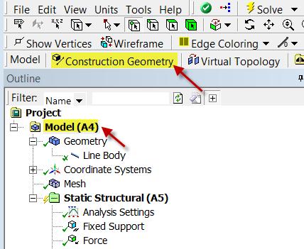
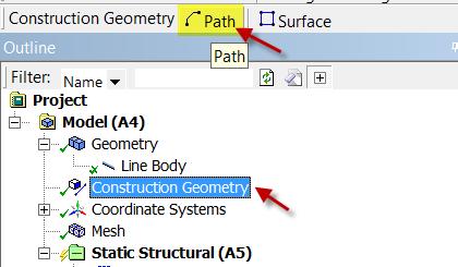
27 Next, right click on the Beam Tool folder, then click on Insert, then click on Beam Tool > Stress > Maximum Bending Stress as shown below. Bending Moment along the Beam Now, we will set up a result object for the bending moment along the beam. We will do this by setting up a "path" along the line body. To set up a path, click on in the Outline window. This will launch the Model toolbar in the Menu Bar. In the Model toolbar, press Construction Geometry Tool bar, then press to create a path. which will bring up the 27
28 28

29 In the Details window, notice that the default path type is Two Points. We need to change that to Edge. Next, using the Edge Selection filter select the line body in the Graphicswindow. Back in the Details of "Path" window, select Geometry > Apply. Rename it "neutral axis". 29


30 Now that we have created the path, we need to create a solution object that gives the bending moment along the path. Click on in the Outline window to bring up the solution menu, then select Beam Results > Bending Moment. 30


31 In the Details of "Total Bending Moment" window, change Scoping Method to Path. Next, define the Path parameter to neutral axis (the path we created). Directional Bending Moment We would also like to look at the bending moment in a specific direction. Repeat the above steps to setup another bending moment results object. In the details window of the new bending moment, change the type to Directional Bending Momentinstead of the default Total Bending Moment. Change the orientation to Z axis. Solve In order to solve, click on the solve button,, which is located near the top of the Setup window. ANSYS will obtain the numerical solution where the ANSYS solver will form the stiffness matrix for each beam element, assemble them into the global stiffness matrix and invert it to get the nodal displacements and slopes. It will then extract the requested results and populate the results objects in the tree. 31


32 Step 6: Numerical Results Total Deformation First, examine the total deformation by clicking on the Total Deformation object in the tree. Turn on the Undeformed Wireframe as shown below. With 10 line elements, you should see the following output for the total deformation. If you turn off View > Thick Shells and Beams, you will see the deformation of the line elements. The 3D beam view is constructed from this. The maximum deformation is m which matches the hand-calculation value from the Pre-Analysis. When ANSYS displays the beam deformation, it just connects the displacements at nodes by straight lines. The display ignores the fact that we also have the slope at the nodes. So you'll see an unphysical-looking kinked line in the deformation display. This is a shortcoming of the display, not of the underlying beam element formulation. You'll see the displayed deformed shape getting smoother as you refine the mesh. 32


33 The beam deformation can be animated by clicking on the play button,, which is located underneath the beam deformation results. This will interpolate between the initial undeformed and final deformed configurations. Maximum Bending Stress In order to examine the maximum bending stress first expand the Beam Tool folder,, which is located under "Solution(A6)". Next, click on the Maximum Bending Stress button,. Note that in this display, ANSYS shows the same value across the cross-section. This visualization is misleading. The maximum bending stress occurs only at the top fiber. The value that ANSYS reports is MPa which matches the value from thepre- Analysis exactly. Bending Moment To view the bending moment along the beam, click Total Bending Moment in theoutline window. You should see the following in the graphics window. 33


34 Also notice that the values were plotted in a graph in the Graph window and also displayed in a table. The values can be exported into a Excel or text file by right-clicking on the table. In the above, pay close attention to maximum and minimum values of the bending moment. At the left end, the bending moment is Nm; the calculation for moment is So this checks out. We also notice that the minimum moment E-10 Nm. Because this value is over 1E-14 smaller that the largest value, it can be assumed to be zero to machine precision. Directional Bending Moment To view the directional bending moment along the beam, click Directional Bending Moment in the Outline window. You should see the following in the graphics window. The Directional Bending Moment gives us the sign along with the magnitude. 34

35 Step 7: Verification and Validation Verification of Maximum Bending Stress and Maximum Total Deformation We have already noted that the ANSYS results compare well to our hand calculations obtained using Euler-Bernoulli beam theory in the pre-analysis. The ANSYS simulation gave MPa for the maximum bending stress and the calculation in the preanalysis yielded MPa. The ANSYS simulation gave m for the total deformation of the beam at x=4 while the calculation from the pre-analysis yielded m. The ANSYS results closely match the hand calculations from the preanalysis. This is one way to verify the solution. Mesh Refinement Another way to verify the solution of a numerical method is to examine the convergence of the solution as the mesh is refined. Generally, the numerical solution should converge to the exact solution as the mesh is refined. In order to refine the mesh, first click on the Mesh tab,, in the tree outline. Next, expand Sizing indetails of Mesh. The mesh will be refined by adjusting the Element Size. The length of the beam is 4 m so if you want n elements then you will need to set the "Element Size" to (4m/n). For instance, if you wanted 20 elements the "Element Size" should be set to (4m/20)=0.2m. After you 35
36 have changed the Element Size to your preference, click on the Solve button,, to recalculate the solution with the new mesh. The table below displays the outputs of the ANSYS simulation for a mesh of 2 elements and a mesh of 10 elements. Total Deformation (m) Theory Values x10^6 2 Element FEA x10^6 10 Element FEA x10^6 Maximum Bending Stress Pa As one can see from the table above the results do not change as the mesh is refined. The reason that the results do not change is as follows: the exact solution for cantilever beam deformation is cubic and for this setup ANSYS uses element BEAM 188 which also uses cubic interpolation. Thus, for the simple cantilever beam setup the numerical method converges very quickly. 36
Module 1.7W: Point Loading of a 3D Cantilever Beam
 Module 1.7W: Point Loading of a 3D Cantilever Beam Table of Contents Page Number Problem Description 2 Theory 2 Workbench Analysis System 4 Engineering Data 5 Geometry 6 Model 11 Setup 13 Solution 14 Results
Module 1.3W Distributed Loading of a 1D Cantilever Beam
 Module 1.3W Distributed Loading of a 1D Cantilever Beam Table of Contents Page Number Problem Description 2 Theory 2 Workbench Analysis System 4 Engineering Data 5 Geometry 6 Model 11 Setup 13 Solution
Finite Element Course ANSYS Mechanical Tutorial Tutorial 4 Plate With a Hole
 Problem Specification Finite Element Course ANSYS Mechanical Tutorial Tutorial 4 Plate With a Hole Consider the classic example of a circular hole in a rectangular plate of constant thickness. The plate
ANSYS Workbench Guide
 ANSYS Workbench Guide Introduction This document serves as a step-by-step guide for conducting a Finite Element Analysis (FEA) using ANSYS Workbench. It will cover the use of the simulation package through
Practice to Informatics for Energy and Environment
 Practice to Informatics for Energy and Environment Part 3: Finite Elemente Method Example 1: 2-D Domain with Heat Conduction Tutorial by Cornell University https://confluence.cornell.edu/display/simulation/ansys+-+2d+steady+conduction
Appendix B: Creating and Analyzing a Simple Model in Abaqus/CAE
 Getting Started with Abaqus: Interactive Edition Appendix B: Creating and Analyzing a Simple Model in Abaqus/CAE The following section is a basic tutorial for the experienced Abaqus user. It leads you
Aufgabe 1: Dreipunktbiegung mit ANSYS Workbench
 Aufgabe 1: Dreipunktbiegung mit ANSYS Workbench Contents Beam under 3-Pt Bending [Balken unter 3-Pkt-Biegung]... 2 Taking advantage of symmetries... 3 Starting and Configuring ANSYS Workbench... 4 A. Pre-Processing:
Exercise 1: 3-Pt Bending using ANSYS Workbench
 Exercise 1: 3-Pt Bending using ANSYS Workbench Contents Starting and Configuring ANSYS Workbench... 2 1. Starting Windows on the MAC... 2 2. Login into Windows... 2 3. Start ANSYS Workbench... 2 4. Configuring
Creating and Analyzing a Simple Model in Abaqus/CAE
 Appendix B: Creating and Analyzing a Simple Model in Abaqus/CAE The following section is a basic tutorial for the experienced Abaqus user. It leads you through the Abaqus/CAE modeling process by visiting
CE366/ME380 Finite Elements in Applied Mechanics I Fall 2007
 CE366/ME380 Finite Elements in Applied Mechanics I Fall 2007 FE Project 1: 2D Plane Stress Analysis of acantilever Beam (Due date =TBD) Figure 1 shows a cantilever beam that is subjected to a concentrated
Introduction To Finite Element Analysis
 Creating a Part In this part of the tutorial we will introduce you to some basic modelling concepts. If you are already familiar with modelling in Pro Engineer you will find this section very easy. Before
Module 1.5: Moment Loading of a 2D Cantilever Beam
 Module 1.5: Moment Loading of a D Cantilever Beam Table of Contents Page Number Problem Description Theory Geometry 4 Preprocessor 7 Element Type 7 Real Constants and Material Properties 8 Meshing 9 Loads
Module 1.6: Distributed Loading of a 2D Cantilever Beam
 Module 1.6: Distributed Loading of a 2D Cantilever Beam Table of Contents Page Number Problem Description 2 Theory 2 Geometry 4 Preprocessor 7 Element Type 7 Real Constants and Material Properties 8 Meshing
Exercise 1. 3-Point Bending Using the Static Structural Module of. Ansys Workbench 14.0
 Exercise 1 3-Point Bending Using the Static Structural Module of Contents Ansys Workbench 14.0 Learn how to...1 Given...2 Questions...2 Taking advantage of symmetries...2 A. Getting started...3 A.1 Choose
Module 1.7: Point Loading of a 3D Cantilever Beam
 Module 1.7: Point Loading of a D Cantilever Beam Table of Contents Page Number Problem Description Theory Geometry 4 Preprocessor 6 Element Type 6 Material Properties 7 Meshing 8 Loads 9 Solution 15 General
FOUNDATION IN OVERCONSOLIDATED CLAY
 1 FOUNDATION IN OVERCONSOLIDATED CLAY In this chapter a first application of PLAXIS 3D is considered, namely the settlement of a foundation in clay. This is the first step in becoming familiar with the
Module 1.2: Moment of a 1D Cantilever Beam
 Module 1.: Moment of a 1D Cantilever Beam Table of Contents Page Number Problem Description Theory Geometry Preprocessor 6 Element Type 6 Real Constants and Material Properties 7 Meshing 9 Loads 10 Solution
Torsional-lateral buckling large displacement analysis with a simple beam using Abaqus 6.10
 Torsional-lateral buckling large displacement analysis with a simple beam using Abaqus 6.10 This document contains an Abaqus tutorial for performing a buckling analysis using the finite element program
Tutorial 1: Welded Frame - Problem Description
 Tutorial 1: Welded Frame - Problem Description Introduction In this first tutorial, we will analyse a simple frame: firstly as a welded frame, and secondly as a pin jointed truss. In each case, we will
Analysis Steps 1. Start Abaqus and choose to create a new model database
 Source: Online tutorials for ABAQUS Problem Description The two dimensional bridge structure, which consists of steel T sections (b=0.25, h=0.25, I=0.125, t f =t w =0.05), is simply supported at its lower
Chapter 6. Concept Modeling. ANSYS, Inc. Proprietary Inventory # May 11, ANSYS, Inc. All rights reserved.
 Chapter 6 Concept Modeling 6-1 Contents Concept Modeling Creating Line Bodies Modifying i Line Bodies Cross Sections Cross Section Alignment Cross Section Offset Surfaces From Lines Surfaces From Sketches
ME 442. Marc/Mentat-2011 Tutorial-1
 ME 442 Overview Marc/Mentat-2011 Tutorial-1 The purpose of this tutorial is to introduce the new user to the MSC/MARC/MENTAT finite element program. It should take about one hour to complete. The MARC/MENTAT
Visit the following websites to learn more about this book:
 Visit the following websites to learn more about this book: 6 Introduction to Finite Element Simulation Historically, finite element modeling tools were only capable of solving the simplest engineering
Structural static analysis - Analyzing 2D frame
 Structural static analysis - Analyzing 2D frame In this tutorial we will analyze 2D frame (see Fig.1) consisting of 2D beams with respect to resistance to two different kinds of loads: (a) the downward
Learning Module 8 Shape Optimization
 Learning Module 8 Shape Optimization What is a Learning Module? Title Page Guide A Learning Module (LM) is a structured, concise, and self-sufficient learning resource. An LM provides the learner with
SETTLEMENT OF A CIRCULAR FOOTING ON SAND
 1 SETTLEMENT OF A CIRCULAR FOOTING ON SAND In this chapter a first application is considered, namely the settlement of a circular foundation footing on sand. This is the first step in becoming familiar
ES 230 Strengths Intro to Finite Element Modeling & Analysis Homework Assignment 2
 ES 230 Strengths Intro to Finite Element Modeling & Analysis Homework Assignment 2 In this homework assignment you will use your rapidly developing ANSYS skill set to model and analyze three different
Structural static analysis - Analyzing 2D frame
 Structural static analysis - Analyzing 2D frame In this tutorial we will analyze 2D frame (see Fig.1) consisting of 2D beams with respect to resistance to two different kinds of loads: (a) the downward
Module 3: Buckling of 1D Simply Supported Beam
 Module : Buckling of 1D Simply Supported Beam Table of Contents Page Number Problem Description Theory Geometry 4 Preprocessor 7 Element Type 7 Real Constants and Material Properties 8 Meshing 9 Solution
Chapter 3 Analysis of Original Steel Post
 Chapter 3. Analysis of original steel post 35 Chapter 3 Analysis of Original Steel Post This type of post is a real functioning structure. It is in service throughout the rail network of Spain as part
FINITE ELEMENT ANALYSIS OF A PLANAR TRUSS
 Problem Description: FINITE ELEMENT ANALYSIS OF A PLANAR TRUSS Instructor: Professor James Sherwood Revised: Dimitri Soteropoulos Programs Utilized: Abaqus/CAE 6.11-2 This tutorial explains how to build
Pro MECHANICA STRUCTURE WILDFIRE 4. ELEMENTS AND APPLICATIONS Part I. Yves Gagnon, M.A.Sc. Finite Element Analyst & Structural Consultant SDC
 Pro MECHANICA STRUCTURE WILDFIRE 4 ELEMENTS AND APPLICATIONS Part I Yves Gagnon, M.A.Sc. Finite Element Analyst & Structural Consultant SDC PUBLICATIONS Schroff Development Corporation www.schroff.com
Exercise 2: Mesh Resolution, Element Shapes, Basis Functions & Convergence Analyses
 Exercise 2: Mesh Resolution, Element Shapes, Basis Functions & Convergence Analyses Goals In this exercise, we will explore the strengths and weaknesses of different element types (tetrahedrons vs. hexahedrons,
NonLinear Analysis of a Cantilever Beam
 NonLinear Analysis of a Cantilever Beam Introduction This tutorial was created using ANSYS 7.0 The purpose of this tutorial is to outline the steps required to do a simple nonlinear analysis of the beam
Verification of Laminar and Validation of Turbulent Pipe Flows
 1 Verification of Laminar and Validation of Turbulent Pipe Flows 1. Purpose ME:5160 Intermediate Mechanics of Fluids CFD LAB 1 (ANSYS 18.1; Last Updated: Aug. 1, 2017) By Timur Dogan, Michael Conger, Dong-Hwan
Simulation and Validation of Turbulent Pipe Flows
 Simulation and Validation of Turbulent Pipe Flows ENGR:2510 Mechanics of Fluids and Transport Processes CFD LAB 1 (ANSYS 17.1; Last Updated: Oct. 10, 2016) By Timur Dogan, Michael Conger, Dong-Hwan Kim,
Finite Element Analysis using ANSYS Mechanical APDL & ANSYS Workbench
 Finite Element Analysis using ANSYS Mechanical APDL & ANSYS Workbench Course Curriculum (Duration: 120 Hrs.) Section I: ANSYS Mechanical APDL Chapter 1: Before you start using ANSYS a. Introduction to
Finite Element Analysis Using Creo Simulate 4.0
 Introduction to Finite Element Analysis Using Creo Simulate 4.0 Randy H. Shih SDC PUBLICATIONS Better Textbooks. Lower Prices. www.sdcpublications.com Powered by TCPDF (www.tcpdf.org) Visit the following
FINITE ELEMENT ANALYSIS OF A PROPPED CANTILEVER BEAM
 FINITE ELEMENT ANALYSIS OF A PROPPED CANTILEVER BEAM Problem Description: Instructor: Professor James Sherwood Revised: Venkat Putcha, Dimitri Soteropoulos Programs Utilized: HyperMesh Desktop 12.0, OptiStruct,
FEA BENDING, TORSION, TENSION, and SHEAR TUTORIAL in CATIA
 1 FEA BENDING, TORSION, TENSION, and SHEAR TUTORIAL in CATIA This tutorial shows the basics of a solid bending, torsional, tension, and shear FEA (Finite Elemental Analysis) model in CATIA. Torsion - page
Start AxisVM by double-clicking the AxisVM icon in the AxisVM folder, found on the Desktop, or in the Start, Programs Menu.
 1. BEAM MODEL Start New Start AxisVM by double-clicking the AxisVM icon in the AxisVM folder, found on the Desktop, or in the Start, Programs Menu. Create a new model with the New Icon. In the dialogue
ME Optimization of a Frame
 ME 475 - Optimization of a Frame Analysis Problem Statement: The following problem will be analyzed using Abaqus. 4 7 7 5,000 N 5,000 N 0,000 N 6 6 4 3 5 5 4 4 3 3 Figure. Full frame geometry and loading
Exercise 1. 3-Point Bending Using the GUI and the Bottom-up-Method
 Exercise 1 3-Point Bending Using the GUI and the Bottom-up-Method Contents Learn how to... 1 Given... 2 Questions... 2 Taking advantage of symmetries... 2 A. Preprocessor (Setting up the Model)... 3 A.1
ANSYS AIM Tutorial Structural Analysis of a Plate with Hole
 ANSYS AIM Tutorial Structural Analysis of a Plate with Hole Author(s): Sebastian Vecchi, ANSYS Created using ANSYS AIM 18.1 Problem Specification Pre-Analysis & Start Up Analytical vs. Numerical Approaches
ANSYS. Geometry. Material Properties. E=2.8E7 psi v=0.3. ansys.fem.ir Written By:Mehdi Heydarzadeh Page 1
 Attention: This tutorial is outdated, you will be redirected automatically to the new site. If you are not redirected, click this link to the confluence site. Problem Specification Geometry Material Properties
FINITE ELEMENT ANALYSIS OF A PROPPED CANTILEVER BEAM
 FINITE ELEMENT ANALYSIS OF A PROPPED CANTILEVER BEAM Problem Description: Instructor: Professor James Sherwood Revised: Venkat Putcha, Dimitri Soteropoulos, Sanjay Nainani Programs Utilized: HyperMesh
The Generate toolbar has convenient tools to create typical structural shapes.
 Frame Analysis Using Multiframe 1. The software is on the computers in the College of Architecture in Programs under the Windows Start menu (see https://wikis.arch.tamu.edu/display/helpdesk/computer+accounts
CHAPTER 8 FINITE ELEMENT ANALYSIS
 If you have any questions about this tutorial, feel free to contact Wenjin Tao (w.tao@mst.edu). CHAPTER 8 FINITE ELEMENT ANALYSIS Finite Element Analysis (FEA) is a practical application of the Finite
Finite Element Method. Chapter 7. Practical considerations in FEM modeling
 Finite Element Method Chapter 7 Practical considerations in FEM modeling Finite Element Modeling General Consideration The following are some of the difficult tasks (or decisions) that face the engineer
Abaqus/CAE (ver. 6.12) Vibrations Tutorial
 Vibrations Tutorial") Abaqus/CAE (ver. 6.12) Vibrations Tutorial Problem Description The two dimensional bridge structure, which consists of steel T sections, is simply supported at its lower corners. Determine the first 10
Abaqus/CAE (ver. 6.12) Vibrations Tutorial Problem Description The two dimensional bridge structure, which consists of steel T sections, is simply supported at its lower corners. Determine the first 10
Exercise 2: Bike Frame Analysis
 Exercise 2: Bike Frame Analysis This exercise will analyze a new, innovative mountain bike frame design under structural loads. The objective is to determine the maximum stresses in the frame due to the
Exercise 2: Bike Frame Analysis
 Exercise 2: Bike Frame Analysis This exercise will analyze a new, innovative mountain bike frame design under structural loads. The objective is to determine the maximum stresses in the frame due to the
FEA of Composites Classical Lamination Theory Example 1
 FEA of Composites Classical Lamination Theory Example 1 22.514 Instructor: Professor James Sherwood Author: Dimitri Soteropoulos Revised by Jacob Wardell Problem Description: A four layer [0/90] s graphite-epoxy
In part 2, we demonstrate the following additional topics:
 Problem description In this problem, we analyze a simple beam structure. Each part of this lesson shows the solution of one of the analyses. In part 1, we demonstrate the following topics: Starting up/shutting
Two Dimensional Truss
 Two Dimensional Truss Introduction This tutorial was created using ANSYS 7.0 to solve a simple 2D Truss problem. This is the first of four introductory ANSYS tutorials. Problem Description Determine the
Lab#5 Combined analysis types in ANSYS By C. Daley
 Engineering 5003 - Ship Structures I Lab#5 Combined analysis types in ANSYS By C. Daley Overview In this lab we will model a simple pinned column using shell elements. Once again, we will use SpaceClaim
Advance Design. Tutorial
 TUTORIAL 2018 Advance Design Tutorial Table of Contents About this tutorial... 1 How to use this guide... 3 Lesson 1: Preparing and organizing your model... 4 Step 1: Start Advance Design... 5 Step 2:
Generative Part Structural Analysis Fundamentals
 CATIA V5 Training Foils Generative Part Structural Analysis Fundamentals Version 5 Release 19 September 2008 EDU_CAT_EN_GPF_FI_V5R19 About this course Objectives of the course Upon completion of this course
Workshop 15. Single Pass Rolling of a Thick Plate
 Introduction Workshop 15 Single Pass Rolling of a Thick Plate Rolling is a basic manufacturing technique used to transform preformed shapes into a form suitable for further processing. The rolling process
Abaqus/CAE (ver. 6.9) Vibrations Tutorial
 Vibrations Tutorial") Abaqus/CAE (ver. 6.9) Vibrations Tutorial Problem Description The two dimensional bridge structure, which consists of steel T sections, is simply supported at its lower corners. Determine the first 10
Abaqus/CAE (ver. 6.9) Vibrations Tutorial Problem Description The two dimensional bridge structure, which consists of steel T sections, is simply supported at its lower corners. Determine the first 10
Introduction to Finite Element Analysis using ANSYS
 Introduction to Finite Element Analysis using ANSYS Sasi Kumar Tippabhotla PhD Candidate Xtreme Photovoltaics (XPV) Lab EPD, SUTD Disclaimer: The material and simulations (using Ansys student version)
Abaqus CAE Tutorial 1: 2D Plane Truss
 ENGI 7706/7934: Finite Element Analysis Abaqus CAE Tutorial 1: 2D Plane Truss Lab TA: Xiaotong Huo EN 3029B xh0381@mun.ca Download link for Abaqus student edition: http://academy.3ds.com/software/simulia/abaqus-student-edition/
Module 4A: Creating the 3D Model of Right and Oblique Pyramids
 Inventor (5) Module 4A: 4A- 1 Module 4A: Creating the 3D Model of Right and Oblique Pyramids In Module 4A, we will learn how to create 3D solid models of right-axis and oblique-axis pyramid (regular or
Simulation of Turbulent Flow around an Airfoil
 1. Purpose Simulation of Turbulent Flow around an Airfoil ENGR:2510 Mechanics of Fluids and Transfer Processes CFD Lab 2 (ANSYS 17.1; Last Updated: Nov. 7, 2016) By Timur Dogan, Michael Conger, Andrew
Installation Guide. Beginners guide to structural analysis
 Installation Guide To install Abaqus, students at the School of Civil Engineering, Sohngaardsholmsvej 57, should log on to \\studserver, whereas the staff at the Department of Civil Engineering should
Verification and Validation of Turbulent Flow around a Clark-Y Airfoil
 1 Verification and Validation of Turbulent Flow around a Clark-Y Airfoil 1. Purpose ME:5160 Intermediate Mechanics of Fluids CFD LAB 2 (ANSYS 19.1; Last Updated: Aug. 7, 2018) By Timur Dogan, Michael Conger,
Appendix: To be performed during the lab session
 Appendix: To be performed during the lab session Flow over a Cylinder Two Dimensional Case Using ANSYS Workbench Simple Mesh Latest revision: September 18, 2014 The primary objective of this Tutorial is
Prescribed Deformations
 u Prescribed Deformations Outline 1 Description 2 Finite Element Model 2.1 Geometry Definition 2.2 Properties 2.3 Boundary Conditions 2.3.1 Constraints 2.3.2 Prescribed Deformation 2.4 Loads 2.4.1 Dead
Structural & Thermal Analysis using the ANSYS Workbench Release 11.0 Environment. Kent L. Lawrence
 ANSYS Workbench Tutorial Structural & Thermal Analysis using the ANSYS Workbench Release 11.0 Environment Kent L. Lawrence Mechanical and Aerospace Engineering University of Texas at Arlington SDC PUBLICATIONS
TUTORIAL 7: Stress Concentrations and Elastic-Plastic (Yielding) Material Behavior Initial Project Space Setup Static Structural ANSYS ZX Plane
 Material Behavior Initial Project Space Setup Static Structural ANSYS ZX Plane") TUTORIAL 7: Stress Concentrations and Elastic-Plastic (Yielding) Material Behavior In this tutorial you will learn how to recognize and deal with a common modeling issues involving stress concentrations
TUTORIAL 7: Stress Concentrations and Elastic-Plastic (Yielding) Material Behavior In this tutorial you will learn how to recognize and deal with a common modeling issues involving stress concentrations
Supersonic Flow Over a Wedge
 SPC 407 Supersonic & Hypersonic Fluid Dynamics Ansys Fluent Tutorial 2 Supersonic Flow Over a Wedge Ahmed M Nagib Elmekawy, PhD, P.E. Problem Specification A uniform supersonic stream encounters a wedge
In-plane principal stress output in DIANA
 analys: linear static. class: large. constr: suppor. elemen: hx24l solid tp18l. load: edge elemen force node. materi: elasti isotro. option: direct. result: cauchy displa princi stress total. In-plane
Lateral Loading of Suction Pile in 3D
 Lateral Loading of Suction Pile in 3D Buoy Chain Sea Bed Suction Pile Integrated Solver Optimized for the next generation 64-bit platform Finite Element Solutions for Geotechnical Engineering 00 Overview
Structural & Thermal Analysis Using the ANSYS Workbench Release 12.1 Environment
 ANSYS Workbench Tutorial Structural & Thermal Analysis Using the ANSYS Workbench Release 12.1 Environment Kent L. Lawrence Mechanical and Aerospace Engineering University of Texas at Arlington SDC PUBLICATIONS
Simulation of Turbulent Flow over the Ahmed Body
 1 Simulation of Turbulent Flow over the Ahmed Body ME:5160 Intermediate Mechanics of Fluids CFD LAB 4 (ANSYS 18.1; Last Updated: Aug. 18, 2016) By Timur Dogan, Michael Conger, Dong-Hwan Kim, Maysam Mousaviraad,
WORKSHOP 6.3 WELD FATIGUE USING NOMINAL STRESS METHOD. For ANSYS release 14
 WORKSHOP 6.3 WELD FATIGUE USING NOMINAL STRESS METHOD For ANSYS release 14 Objective: In this workshop, a weld fatigue analysis on a VKR-beam with a plate on top using the nominal stress method is demonstrated.
ANSYS 5.6 Tutorials Lecture # 2 - Static Structural Analysis
 R50 ANSYS 5.6 Tutorials Lecture # 2 - Static Structural Analysis Example 1 Static Analysis of a Bracket 1. Problem Description: The objective of the problem is to demonstrate the basic ANSYS procedures
Tutorial. Spring Foundation
 Page i Preface This tutorial provides an example on how to model a spring foundation using BRIGADE/Plus. Page ii Contents 1 OVERVIEW... 1 2 GEOMETRY... 1 3 MATERIAL AND SECTION PROPERTIES... 2 4 STEP DEFINITION...
Wall thickness= Inlet: Prescribed mass flux. All lengths in meters kg/m, E Pa, 0.3,
 Problem description Problem 30: Analysis of fluid-structure interaction within a pipe constriction It is desired to analyze the flow and structural response within the following pipe constriction: 1 1
NonLinear Materials AH-ALBERTA Web:
 NonLinear Materials Introduction This tutorial was completed using ANSYS 7.0 The purpose of the tutorial is to describe how to include material nonlinearities in an ANSYS model. For instance, the case
Introduction And Overview ANSYS, Inc. All rights reserved. 1 ANSYS, Inc. Proprietary
 Introduction And Overview 2006 ANSYS, Inc. All rights reserved. 1 ANSYS, Inc. Proprietary The ANSYS Workbench represents more than a general purpose engineering tool. It provides a highly integrated engineering
AMPS First Tutorial. Version 3.0, June, 2005
 AMPS First Tutorial Version 3.0, June, 2005 Copyright AMPS Technologies Company 2004-2005 Table of Contents 3D Beam Modeling Tutroial... 1 A Cantilever Block Beam Tutorial... 1 Create a Solid Beam Model...
TUTORIAL#3. Marek Jaszczur. Boundary Layer on a Flat Plate W1-1 AGH 2018/2019
 TUTORIAL#3 Boundary Layer on a Flat Plate Marek Jaszczur AGH 2018/2019 W1-1 Problem specification TUTORIAL#3 Boundary Layer - on a flat plate Goal: Solution for boudary layer 1. Creating 2D simple geometry
Analysis of a silicon piezoresistive pressure sensor
 Analysis of a silicon piezoresistive pressure sensor This lab uses the general purpose finite element solver COMSOL to determine the stress in the resistors in a silicon piezoresistive pressure sensor
TUTORIAL 2. OBJECTIVE: Use SolidWorks/COSMOS to model and analyze a cattle gate bracket that is subjected to a force of 100,000 lbs.
 TUTORIAL 2 OBJECTIVE: Use SolidWorks/COSMOS to model and analyze a cattle gate bracket that is subjected to a force of 100,000 lbs. GETTING STARTED: 1. Open the SolidWorks program. 2. Open a new part file.
Simulation of Laminar Pipe Flows
 Simulation of Laminar Pipe Flows 57:020 Mechanics of Fluids and Transport Processes CFD PRELAB 1 By Timur Dogan, Michael Conger, Maysam Mousaviraad, Tao Xing and Fred Stern IIHR-Hydroscience & Engineering
Workbench Tutorial Flow Over an Airfoil, Page 1 ANSYS Workbench Tutorial Flow Over an Airfoil
 Workbench Tutorial Flow Over an Airfoil, Page 1 ANSYS Workbench Tutorial Flow Over an Airfoil Authors: Scott Richards, Keith Martin, and John M. Cimbala, Penn State University Latest revision: 17 January
Abaqus CAE Tutorial 6: Contact Problem
 ENGI 7706/7934: Finite Element Analysis Abaqus CAE Tutorial 6: Contact Problem Problem Description In this problem, a segment of an electrical contact switch (steel) is modeled by displacing the upper
Finite Element Analysis Using NEi Nastran
 Appendix B Finite Element Analysis Using NEi Nastran B.1 INTRODUCTION NEi Nastran is engineering analysis and simulation software developed by Noran Engineering, Inc. NEi Nastran is a general purpose finite
Problem description. The FCBI-C element is used in the fluid part of the model.
 Problem description This tutorial illustrates the use of ADINA for analyzing the fluid-structure interaction (FSI) behavior of a flexible splitter behind a 2D cylinder and the surrounding fluid in a channel.
3D SolidWorks Tutorial
 ROCHESTER INSTITUTE OF TECHNOLOGY MICROELECTRONIC ENGINEERING 3D SolidWorks Tutorial Dr. Lynn Fuller webpage: http://people.rit.edu/lffeee Electrical and Microelectronic Engineering Rochester Institute
EXAMPLE 1. Static Analysis of Cantilever Column (Fixed-Base Column)
") EXAMPLE 1 Static Analysis of Cantilever Column (Fixed-Base Column) Calculate the top displacement, axial force, shear force and bending moment diagrams for the fixed base column described in the figure
EXAMPLE 1 Static Analysis of Cantilever Column (Fixed-Base Column) Calculate the top displacement, axial force, shear force and bending moment diagrams for the fixed base column described in the figure
Beams. Lesson Objectives:
 Beams Lesson Objectives: 1) Derive the member local stiffness values for two-dimensional beam members. 2) Assemble the local stiffness matrix into global coordinates. 3) Assemble the structural stiffness
Abaqus/CAE Axisymmetric Tutorial (Version 2016)
") Abaqus/CAE Axisymmetric Tutorial (Version 2016) Problem Description A round bar with tapered diameter has a total load of 1000 N applied to its top face. The bottom of the bar is completely fixed. Determine
Abaqus/CAE Axisymmetric Tutorial (Version 2016) Problem Description A round bar with tapered diameter has a total load of 1000 N applied to its top face. The bottom of the bar is completely fixed. Determine
Introduction to MSC.Patran
 Exercise 1 Introduction to MSC.Patran Objectives: Create geometry for a Beam. Add Loads and Boundary Conditions. Review analysis results. MSC.Patran 301 Exercise Workbook - Release 9.0 1-1 1-2 MSC.Patran
Important Note - Please Read:
 Important Note - Please Read: This tutorial requires version 6.01 or later of SAFE to run successfully. You can determine what version of SAFE you have by starting the program and then clicking the Help
Autodesk Inventor - Basics Tutorial Exercise 1
 Autodesk Inventor - Basics Tutorial Exercise 1 Launch Inventor Professional 2015 1. Start a New part. Depending on how Inventor was installed, using this icon may get you an Inch or Metric file. To be
SAFI Sample Projects. Design of a Steel Structure. SAFI Quality Software Inc. 3393, chemin Sainte-Foy Ste-Foy, Quebec, G1X 1S7 Canada
 SAFI Sample Projects Design of a Steel Structure SAFI Quality Software Inc. 3393, chemin Sainte-Foy Ste-Foy, Quebec, G1X 1S7 Canada Contact: Rachik Elmaraghy, P.Eng., M.A.Sc. Tel.: 1-418-654-9454 1-800-810-9454
A pipe bend is subjected to a concentrated force as shown: y All dimensions in inches. Material is stainless steel.
 Problem description A pipe bend is subjected to a concentrated force as shown: y 15 12 P 9 Displacement gauge Cross-section: 0.432 18 x 6.625 All dimensions in inches. Material is stainless steel. E =
Lab Practical - Finite Element Stress & Deformation Analysis
 Lab Practical - Finite Element Stress & Deformation Analysis Part A The Basics In this example, some of the basic features of a finite element analysis will be demonstrated through the modelling of a simple