CHAPTER 3 RETINAL OPTIC DISC SEGMENTATION
|
|
|
- Cameron Horn
- 5 years ago
- Views:
Transcription
1 60 CHAPTER 3 RETINAL OPTIC DISC SEGMENTATION 3.1 IMPORTANCE OF OPTIC DISC Ocular fundus images provide information about ophthalmic, retinal and even systemic diseases such as hypertension, diabetes, macular degeneration and arteriosclerosis. Detection of normal and abnormal features in retinal images is fundamental and helpful for automatic understanding of these images. Precise localization of the optic disc boundary is an important sub-problem of higher level problems in ophthalmic image processing. Optic disc is a bright yellowish disc with a whitish central cupping through which the central retinal artery and vein pass. Location of optic disc is an important issue in retinal image analysis as it is a significant landmark feature to locate anatomical components in retinal images for vessel tracking and for registering changes within the OD region. Localizing the disc is often necessary to differentiate the disc from other features of the retina and it is a prerequisite for computation of some important diagnostic indices for hypertensive retinopathy based on vasculature. Identification of outer boundary of the optic disc may allow ophthalmologists to quantitatively assess changes in the optic disc over time. OD segmentation is fundamental for establishing a frame of reference within the retinal image and is thus important for any image analysis application. Segmentation is also relevant for automated diagnosis of other ophthalmic pathologies and usually refers to the subsequent task of
2 61 determining the contour of the disc. An important information in digital fundus images is to differentiate between left and right eye. Automated localization of the optic nerve head is particularly important in making a diagnosis of glaucoma because the main symptoms in these cases are the links between the optic nerve, cupping parameters and differences in symmetry between the eyes. This chapter is organized as follows. In section 3.2, an automatic retinal optic disc segmentation algorithm using Differential Windowing (DW) technique in the polar coordinate domain is described. Section 3.3 describes the experimental set up used in the detection of OD. Experimental results for disc boundary extraction are presented in section 3.4. In section 3.5, results of the technique are compared with existing methods in terms of accuracy for few images. 3.2 PROPOSED DW OPTIC DISC SEGMENTATION ALGORITHM Anatomical structures of fundus images include optic disc, optic cup, blood vessels, macula and fovea. Change in the shape, color or depth of the optic disc is an indicator of various ophthalmic pathologies especially for glaucoma. Although OD has well defined features and characteristics, localizing the optic disc automatically and in a robust manner is not a straight forward process, since the appearance of OD may vary significantly due to retinal diseases and the disc size also varies from one person to another. Detection is critical due to the geometric relationship that exists between the vasculature and the position of the optic disc in the retina. Optic disc detection remains a problematic task due to hue changes within the optic disc boundary. OD segmentation is difficult since some parts of the disc boundary are not well defined and some parts are partly obscured by the
3 62 blood vessels in the retinal image which makes the disc shape more complicated. General purpose algorithms often fail to segment the optic disc due to fuzzy boundaries, inconsistent image contrast or missing edge features. Disc boundary detection is therefore aimed to correctly segment the OD by detecting the boundary between the retina and the nerve head. Flow diagram of the proposed DW disc segmentation algorithm is shown in Figure 3.1. Input image Mask generation Optic cup point detection ROI circle localization Left or right eye Blood vessel erasure Cartesian to Polar conversion Optic disc boundary Polar to Cartesian conversion Polygon closing Figure 3.1 Flow diagram to segment optic disc
 with maximum value, the technique is known as")

4 63 Differential Windowing technique is a combination of edge detection and local maxima finding. As edge detection involves difference operation and maxima finding refers to identifying the window (region) with maximum value, the technique is known as differential window. OD boundary is detected using the following steps. Color fundus image shown in Figure 3.2 is used as the input image. Figure 3.2 Input image Mask Generation Mask generation aims to label the pixels belonging to the circular retinal fundus region in the entire image and exclude the background of the image from further calculations and processing. (a) (b) Figure 3.3 Mask generation


5 64 a) Retinal images are acquired in Red Green Blue (RGB) mode by fundus camera. Green plane is considered for OD extraction since it provides better contrast between the optic disc and the retinal tissue. Region with intensity greater than 5% of the average intensity in the green plane is selected. As optic disc is the brightest anatomical structure in a retinal image, the highest intensity pixels that contain areas in the optic disc are chosen. A binary mask shown in Figure 3.3(a) is generated initially and it is the result of thresholding operation. b) Erosion is performed with a circular window of radius equal to half the optic disc width. This operation will remove the isolated pixels with high intensity. Figure 3.3(b) is the result of erosion operation (circular window) done on the threshold image. Figure 3.3(b) represents a mask used for the Region of Interest (ROI). This mask is used since the disc region will not be present at the edges of the mask. Image Preprocessing Preprocessing highlights the optic disc region from the background region. c) Image opening is then performed with a circular window of radius equal to the optic disc width and it is shown in Figure 3.4(a). d) Opened image subtracted from the input image is shown in Figure 3.4(b). (a) (b) Figure 3.4 Image preprocessing
. f) Maximum value point that gives the optic cup point is shown in Figure 3.5(b) (a) (b) Figure 3.")
 and ROI region is shown in Figure 3.6(b).")
6 65 Optic cup point detection e) Average filtering is done with a circular window of radius 5% of the disc width to cover the entire optic disc region as shown in Figure 3.5(a). f) Maximum value point that gives the optic cup point is shown in Figure 3.5(b) (a) (b) Figure 3.5 Optic cup point detection ROI Circle Localization The circle parameters are set and the Region of Interest (ROI) is clipped as the bounding rectangle of the circle. ROI circle radius is set as 1.5 times the disc width parameter as in Figure 3.6(a) and ROI region is shown in Figure 3.6(b). (a) (b) Figure 3.6 ROI circle localization

 Left Eye (b) Right Eye Figure 3.7 Identification of left and right eye For a left (right) eye, the blood vessel convergence happens to the left (right) side of the detected optic cup point.")
7 66 Left or Right Eye Identification g) Blood vessels are extracted in the ROI. If blood vessels converge to the left, it is left eye. Else, it is right eye. i. Image closing is done with optic disc width. ii. Image subtraction of the closed image from the input image is performed. iii. In the subtracted image, if the mean value of left half image is greater (smaller) than the right half, then it is left (right) eye as shown in Figures 3.7(a) and 3.7(b). (a) Left Eye (b) Right Eye Figure 3.7 Identification of left and right eye For a left (right) eye, the blood vessel convergence happens to the left (right) side of the detected optic cup point. The direction of theta is set. iv. For left eye, theta is measured in counter clock-wise direction. v. For right eye, theta is measured in clock-wise direction as given in Figure 3.8.

8 67 Figure 3.8 Direction of theta Blood Vessel Erasure Dilation is performed followed by erosion operation in the ROI image. A circular window of maximum vessel width as radius is used for dilation and erosion. The impact of blood vessels in the optic disc and cup region is removed using morphological operations as in Figure 3.9. Figure 3.9 Blood vessel erasure Cartesian to Polar Conversion The circle with optic cup point as center and 1.5 times the disc width as radius is converted from cartesian to polar coordinate system along the positive theta direction as shown in Figure In the polar coordinate system, the radial and angular resolution in terms of the disc width is given as radial resolution = 1.5 disc width (3.1) angular resolution = 3 disc width (3.2)
9 68 Figure 3.10 Image representation in Cartesian to Polar form Figure 3.11 Cartesian to Polar conversion In Figure 3.10, (x-axis) represents the angular shift of the pixels under study from the horizontal direction and R (y-axis) represents the distance of the pixels under study from the detected optic cup point. Figure 3.11 describes the experimental result obtained during the image conversion. Optic disc boundary extraction Left and right eyes are identified using the optic cup point. Differential windowing (DW) technique is performed in the polar converted image and it is represented as in Figure Figure 3.12 Representation of DW technique
10 69 In order to identify the first point on the OD boundary, zero degree axis is chosen initially as there are no blood vessel interruption along this axis. Once the first point is identified, tracing of further points becomes easier. Here x represents the columns (horizontal direction) and y represents the rows (vertical direction). To obtain the OD boundary, window regions of size r X c are analyzed at the upper side and lower side of the search pixel. I Lower (x,y) represents mean intensity of a small window below the detected optic disc boundary in the previous iteration. I Upper (x,y) represents mean intensity of a small window above the detected optic disc boundary in the previous iteration. Aim is to find the boundary that maximizes the difference between I Upper (x,y) and I Lower (x,y) as represented in Figure In each iteration, the windows for I Lower (x,y) and I Upper (x,y) progresses in the forward direction of theta. The window size used is r X (2c + 1) and w is the increment in the horizontal direction for each new point. (2m + 1) represents the search space in the vertical direction. Totally 21 pixels (m=10) are searched with the centre of the search space as the detected boundary point from the previous column (previous theta value).this is done as the new boundary point of the current column will not vary far away from the previous boundary point of previous column. From the initial boundary point, DW operation is done at each degrees of the radial axis to obtain the OD boundary at each column of the polar converted image. If the i th point on the optic disc boundary has coordinates (x i, y i ), the (i+1) th point, (x i+1, y i+1 ), is computed iteratively as x = x + w (3.3) y = arg [ max I (x, y) I (x, y) ] (3.4)
11 70 (3.5) (3.6) OD is characterized by high intensity pixels. It has bright pixels on one side and less bright pixels on the other side. In the search space of 21 pixels, pixels with high intensity value has to be found. So the difference between average value of the upper window and lower window is found. Maximum of this difference value contributes to the disc boundary point and a point is obtained for each column as shown in Figure w is the increment in the direction for each new point. The column gets updated, x i becomes x i +w and the row depends on the pixel. Procedure is repeated for 1, 2 360, to get the entire boundary region. Figure 3.13 OD boundary extraction Polar to Cartesian Conversion In the fundus image transformed to a polar coordinate, image columns and rows correspond to angle and distance from the center of the optic disc respectively. After polar processing, the resultant image may then be transformed back to rectangular coordinates as shown in Figure 3.14 to generate a closed contour and to retain the rectangular shape of the image so that accurate measurements can be done on the identified features. Figure 3.14 Polar to Cartesian conversion
12 71 Polygon Closing Contour boundary detected in the polar coordinate system need not be a continuous closed boundary, when converted back to cartesian coordinate system. So, to create connected closed boundary, polygon closing is performed. The closed polygon in Figure 3.15 represents the optic disc boundary. Figure 3.15 Polygon closing 3.3 EXPERIMENTAL SETUP Algorithm tested on the database images from Digital Retinal Images for Vessel Extraction (DRIVE) database is given in Table 3.1. Images were acquired using a Canon CR5 non mydriatic 3 CCD camera with a 45 FOV. Each image was captured using 8 bits per color plane at 768 X 584 pixels. The FOV of each image is circular with a diameter of approximately 540 pixels. The images used in this technique are hand labeled by the observers trained by the ophthalmologists. Using the proposed technique, the optic disc was localized correctly in all the 40 images and the contour of the optic disc was found accurately. Though the contrast of the image is too low in few of the images, boundary of the optic disc was detected correctly. The proposed algorithm was developed in Matlab 7.8 Image processing toolbox. Table 3.1 lists the values of the different primary and derived parameters used in the proposed algorithm.


 10")


13 72 Table 3.1 Parameters used in the disc segmentation Parameter Value in Pixels Disc Width 200 Maximum Vessel Width 25 Average filtering Window radius 10 ROI Circle Radius 300 Blood Vessel Erasure: Window radius 25 Polar Coordinate: Radial Resolution 300 Polar Coordinate: Angular Resolution 1885 Differential filtering: search space parameter m 10 Differential filtering: window size parameter r (rows) 10 Differential filtering: window size parameter c (columns) 25 Differential filtering: Horizontal increment w EXPERIMENTAL RESULTS For a left eye, the blood vessel converges to the left side of the detected optic cup point as shown in Figure Figure 3.16 Few sample results for optic cup point detection in left eye


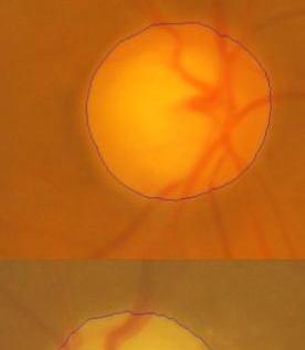
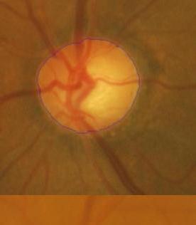
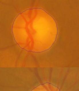
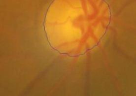
14 73 For a right eye, the blood vessel converges to the right side of the detected optic cup point as shown in Figure Figure 3.17 Few sample results for optic cup point detection in right eye in Figure Sample results of disc boundary extraction for 28 images are shown


15 74 Figure 3.18 Few sample results for optic disc boundary detection 3.5 PERFORMANCE ANALYSIS OF OPTIC DISC BOUNDARY DETECTION The proposed method was tested on a dataset which includes normal and abnormal retinal images collected from Aravind eye hospital, Madurai. Fundus images used in this work are captured by Topcon TRC50 EX mydriatic fundus camera under a fixed protocol with a 50 field of view, centered on the optic disc with a dimension of 1900 x1600 pixels at 24 bits true color images. Table 3.2 shows an accuracy measure for boundary localization for thirty real time retinal images. For each image ground truth was collected from two glaucoma experts and to compensate for inter observer
16 75 marking variations, an average boundary is obtained for each image by averaging the boundaries from the two experts. The optic disc boundary manually marked by an experienced ophthalmologist is set to be ground truth. Table 3.2 Accuracy for optic disc boundary detection Image ( ) (G ) Accuracy (%) value in pixels value in pixels A
17 76 An effective measure to evaluate the accuracy of detected optic disc boundary is calculated using the Equation (3.7). A = n ( D) n( D) (3.7) G corresponds to the pixels in the ground truth and D refers to the pixels in the detected optic disc region and n the no of pixels in the region. Assuming ideal case, the detected boundary region D will exactly match with the ground truth boundary G. In this case A becomes 1, and percentage becomes 100. As the detected boundary deviates from the ground truth, A value decreases from 100. The numerator in Equation (3.7) is an indicator of degree of correctness of detected boundary and denominator is an indicator of degree of incorrectness of detected boundary. As the inaccuracy in detected boundary increases, the numerator decreases and denominator increases, thus the overall value A decreases. Thus Equation (3.7) is a good indicator of boundary mismatch between ground truth boundary and detected boundary. Optic disc boundary obtained using DW technique is experimented for 30 real time images and an average accuracy of 97.9 % is achieved. STARE, DRIVE, DIARETDB0, DIARETDB1 are the four publicly available databases used to evaluate the accuracy of the proposed technique. Databases are a) STARE Database (81 images, 605 X 700 pixels) b) DRIVE Database (40 images, 565 X 584 pixels) c) Standard Diabetic Retinopathy Database Calibration Level 0 (DIARETDB0) (130 images, 1500 X 1152 pixels) and d) Standard Diabetic Retinopathy Database Calibration Level 1 (DIARETDB1) (89 images,1500 X 1152 pixels). A comparison of the windowing technique with Maximum Local Variation Method (MLVM), Hough Transform (HT) and Gradient Vector Flow (GVF) snake method in terms of boundary accuracy are shown in Table 3.3.
18 77 Table 3.3 Comparison of average accuracy for detecting optic disc boundary Database No of images MLVM HT GVF DW Accuracy (%) STARE DRIVE DIARETDB DIARETDB Average accuracy for 340 images Accuracy of OD boundary detected using DW technique are compared with the results of MLVM, HT and GVF snake method referred from Giri Babu Kande et al (2009) and are shown from Figure 3.19 to Figure Accuracy(%) Accuracy 0 MLVM HT GVF DW Images Figure 3.19 OD boundary detection for STARE database
19 78 Accuracy(%) Accuracy 90 MLVM HT GVF DW Images Figure 3.20 OD boundary detection for DRIVE database Accuracy(%) MLVM HT GVF DW Images Accuracy Figure 3.21 OD boundary detection for DIARETDB0 database
20 Accuracy(%) Accuracy 75 MLVM HT GVF DW Images Figure 3.22 OD boundary detection for DIARETDB1 database Accuracy(%) MLVM HT GVF DW 0 STARE DRIVE DIARETDB0 DIARETDB1 Images Figure 3.23 Comparison of average accuracy for four databases In order to evaluate the performance of DW technique, the results are compared with the state of results obtained from MLVM, HT and GVF technique as shown in Figure DW technique achieved a success rate of 98.7% in STARE, 100% in DRIVE, 97.7% in DIARETDB0 and 98.8% in
21 80 DIARETDB1 database. DW algorithm achieved an average success rate of 98.5%, that is the OD was correctly detected in 335 images out of 340 images tested, compared to an average accuracy of 89.7% in MLVM method, 87% in HT method and 94.4% in GVF snake method. DW method takes an average time of 5 seconds per image for computation. Classical segmentation algorithms like thresholding, edge detection and region growing techniques cannot find the optic disc boundary correctly as they do not incorporate the edge smoothness and continuity properties. Local variation technique described by Sinthanayothin et al (1999) used the variance of intensity between the adjacent pixels and the blood vessels and detected OD with a specificity of 99.1% and produces incorrect localization for fundus images with a large area of white lesions. In 2D circular HT, the dimensions of the normal circular histogram are reduced from 3 to 2 dimensions by assuming that the approximate OD radius is known. Computations in this technique depend on the number of edge pixels and the number of radii to be matched. During the whole process of finding the centre s and radii, circular Hough Transform has to be iterated each time with the different circles of different radii and some inaccuracies could occur. In the snake based approach, to fit active contour on to the optic disc, the initial contour must be placed near the optic disc boundary, otherwise it leads to wrong convergence. This method captures a range of shape and image variations, but the segmentation accuracy is sensitive to the contour initialization and had a difficulty in progressing into boundary concavities. In gradient vector flow snakes, contour is initialized either manually or automatically and deformation in the contour takes place under the influence of energy term defined on the image gradient or as a post processing step. Snakes initialized automatically with GVF as an external force has to choose various regularization parameters of GVF and snake parameters manually, to represent the smoothness and accuracy of the desired
22 81 boundary. Inspite of its robustness to initialization and increased range of capture, the method takes a long time to converge to object contours. In the proposed DW technique, representation of the images in polar coordinates facilitates the description of local image regions in terms of their radial and tangential characteristics to find a closed contour in the region of interest. The technique detects the boundary correctly though the disc is interrupted by strongly visible blood vessels. The method does not impose any constraints or lead to false positive and false negative points and hence provides an accurate boundary tracing with no loss of data. 3.6 SUMMARY Reliable and automated extraction of optic disc parameters can be a valuable diagnostic assisting resource for clinicians. Much of the prior work has focused on optic disc boundary detection, however the blood vessel occlusion problem has not been well solved. The proposed work has made a few contributions by proposing a novel approach to disc boundary detection which solves the problem of blood vessel occlusions. Optic disc segmentation in the polar coordinate domain gives significant results for the four databases and works with a high accuracy for the real time images. Hough transform has 3-dimensional parameter space such as (x, y, z) coordinate of the center of the ellipse, minor-axis radius and major-axis radius. A higher-dimensional parameter space HT is slow, because of the accumulator array updation with more parameters. Snake based methods for optic disc boundary extractions are slow because the computation of the snake boundary is an iterative process. The proposed method is non-iterative and computationally fast since it does not use any accumulator array. Methodologies for efficient automatic optic disc localization and left and right eye detection using DW technique have been presented in this work. Optic disc boundary was detected in 335 images and the success rate was found to be 98.5%. Left and right eye was
23 82 localized with 100% accuracy. DW algorithm works well even though the input retinal image is in a low contrast condition. The developed methodology has been checked to be independent and stable regardless of image resolution making it possible to work with poor resolution images. The main advantage of this method is that the OD s are detected even though the boundary of the optic disc is not continuous or blurred. When compared to the other approaches like MLVM, HT and GVF, DW technique can detect the disc boundary exactly even though the disc has many distracters. Edge detection and local maxima finding makes the proposed approach robust to blood vessel occlusions, ill defined edges, fuzzy shapes due to pathological changes and noises while maintaining the accuracy. Techniques employed in this system are capable of tracing boundaries of the optic disc sharply with exact contours and helps in improving the diagnostic accuracy thereby reducing the workload of ophthalmologists.
CHAPTER-4 LOCALIZATION AND CONTOUR DETECTION OF OPTIC DISK
 CHAPTER-4 LOCALIZATION AND CONTOUR DETECTION OF OPTIC DISK Ocular fundus images can provide information about ophthalmic, retinal and even systemic diseases such as hypertension, diabetes, macular degeneration
CHAPTER 4 OPTIC CUP SEGMENTATION AND QUANTIFICATION OF NEURORETINAL RIM AREA TO DETECT GLAUCOMA
 83 CHAPTER 4 OPTIC CUP SEGMENTATION AND QUANTIFICATION OF NEURORETINAL RIM AREA TO DETECT GLAUCOMA 4.1 INTRODUCTION Glaucoma damages the optic nerve cells that transmit visual information to the brain.
On the main screen top left side enter your name and specify if you are a clinician or not.
 Document name: SOP_VAMPIRE_ANNOTATION_TOOL Title: VAMPIRE-Annotation Tool Author: Ilaria Pieretti Version: 10 10 Background: VAMPIRE (Vascular Assessment and Measurement Platform for Images of the Retina)
AN ADAPTIVE REGION GROWING SEGMENTATION FOR BLOOD VESSEL DETECTION FROM RETINAL IMAGES
 AN ADAPTIVE REGION GROWING SEGMENTATION FOR BLOOD VESSEL DETECTION FROM RETINAL IMAGES Alauddin Bhuiyan, Baikunth Nath and Joselito Chua Computer Science and Software Engineering, The University of Melbourne,
Tutorial 8. Jun Xu, Teaching Asistant March 30, COMP4134 Biometrics Authentication
 Tutorial 8 Jun Xu, Teaching Asistant csjunxu@comp.polyu.edu.hk COMP4134 Biometrics Authentication March 30, 2017 Table of Contents Problems Problem 1: Answer The Questions Problem 2: Daugman s Method Problem
Gopalakrishna Prabhu.K Department of Biomedical Engineering Manipal Institute of Technology Manipal University, Manipal, India
 00 International Journal of Computer Applications (0975 8887) Automatic Localization and Boundary Detection of Optic Disc Using Implicit Active Contours Siddalingaswamy P. C. Department of Computer science
THE quantification of vessel features, such as length, width,
 1200 IEEE TRANSACTIONS ON MEDICAL IMAGING, VOL. 25, NO. 9, SEPTEMBER 2006 Segmentation of Retinal Blood Vessels by Combining the Detection of Centerlines and Morphological Reconstruction Ana Maria Mendonça,
Geometry-Based Optic Disk Tracking in Retinal Fundus Videos
 Geometry-Based Optic Disk Tracking in Retinal Fundus Videos Anja Kürten, Thomas Köhler,2, Attila Budai,2, Ralf-Peter Tornow 3, Georg Michelson 2,3, Joachim Hornegger,2 Pattern Recognition Lab, FAU Erlangen-Nürnberg
Blood vessel tracking in retinal images
 Y. Jiang, A. Bainbridge-Smith, A. B. Morris, Blood Vessel Tracking in Retinal Images, Proceedings of Image and Vision Computing New Zealand 2007, pp. 126 131, Hamilton, New Zealand, December 2007. Blood
Segmentation of the Optic Disc, Macula and Vascular Arch
 Chapter 4 Segmentation of the Optic Disc, Macula and Vascular Arch M.Niemeijer, M.D. Abràmoff and B. van Ginneken. Segmentation of the Optic Disc, Macula and Vascular Arch in Fundus Photographs. IEEE Transactions
Critique: Efficient Iris Recognition by Characterizing Key Local Variations
 Critique: Efficient Iris Recognition by Characterizing Key Local Variations Authors: L. Ma, T. Tan, Y. Wang, D. Zhang Published: IEEE Transactions on Image Processing, Vol. 13, No. 6 Critique By: Christopher
CHAPTER 6 DETECTION OF MASS USING NOVEL SEGMENTATION, GLCM AND NEURAL NETWORKS
 130 CHAPTER 6 DETECTION OF MASS USING NOVEL SEGMENTATION, GLCM AND NEURAL NETWORKS A mass is defined as a space-occupying lesion seen in more than one projection and it is described by its shapes and margin
Chapter 5. Effective Segmentation Technique for Personal Authentication on Noisy Iris Images
 110 Chapter 5 Effective Segmentation Technique for Personal Authentication on Noisy Iris Images Automated authentication is a prominent goal in computer vision for personal identification. The demand of
Laboratory of Applied Robotics
 Laboratory of Applied Robotics OpenCV: Shape Detection Paolo Bevilacqua RGB (Red-Green-Blue): Color Spaces RGB and HSV Color defined in relation to primary colors Correlated channels, information on both
HOUGH TRANSFORM CS 6350 C V
 HOUGH TRANSFORM CS 6350 C V HOUGH TRANSFORM The problem: Given a set of points in 2-D, find if a sub-set of these points, fall on a LINE. Hough Transform One powerful global method for detecting edges
THE Segmentation of retinal image structures has
 1 Segmentation of Blood Vessels and Optic Disc in Retinal Images Ana Salazar-Gonzalez, Djibril Kaba, Yongmin Li and Xiaohui Liu Abstract Retinal image analysis is increasingly prominent as a non-intrusive
Quantitative Three-Dimensional Imaging of the Posterior Segment with the Heidelberg Retina Tomograph
 Quantitative Three-Dimensional Imaging of the Posterior Segment with the Heidelberg Retina Tomograph Heidelberg Engineering GmbH, Heidelberg, Germany Contents 1 Introduction... 1 2 Confocal laser scanning
Fovea and Optic Disk Detection and Key Performance Indicators Process Automation
 UNIVERSITY OF COIMBRA FACULTY OF SCIENCE AND TECHNOLOGY CRITICAL HEALTH S.A. Fovea and Optic Disk Detection and Key Performance Indicators Process Automation José Manuel Neves Pinão Coimbra, July 2011
CHAPTER 3 BLOOD VESSEL SEGMENTATION
 47 CHAPTER 3 BLOOD VESSEL SEGMENTATION Blood vessels are an internal part of the blood circulatory system and they provide the nutrients to all parts of the eye. In retinal image, blood vessel appears
IRIS SEGMENTATION OF NON-IDEAL IMAGES
 IRIS SEGMENTATION OF NON-IDEAL IMAGES William S. Weld St. Lawrence University Computer Science Department Canton, NY 13617 Xiaojun Qi, Ph.D Utah State University Computer Science Department Logan, UT 84322
Unsurpassed Wide Field Image Quality
 Unsurpassed Wide Field Image Quality EIDON TrueColor Confocal Scanner The latest technology to disclose new imaging quality to eye care professionals in all clinical practices. Many diagnosis of ocular
Image Processing Fundamentals. Nicolas Vazquez Principal Software Engineer National Instruments
 Image Processing Fundamentals Nicolas Vazquez Principal Software Engineer National Instruments Agenda Objectives and Motivations Enhancing Images Checking for Presence Locating Parts Measuring Features
Computer-aided Diagnosis of Retinopathy of Prematurity
 Computer-aided Diagnosis of Retinopathy of Prematurity Rangaraj M. Rangayyan, Faraz Oloumi, and Anna L. Ells Department of Electrical and Computer Engineering, University of Calgary Alberta Children's
Automated Vessel Shadow Segmentation of Fovea-centred Spectral-domain Images from Multiple OCT Devices
 Automated Vessel Shadow Segmentation of Fovea-centred Spectral-domain Images from Multiple OCT Devices Jing Wu a, Bianca S. Gerendas a, Sebastian M. Waldstein a, Christian Simader a and Ursula Schmidt-Erfurth
Types of Edges. Why Edge Detection? Types of Edges. Edge Detection. Gradient. Edge Detection
 Why Edge Detection? How can an algorithm extract relevant information from an image that is enables the algorithm to recognize objects? The most important information for the interpretation of an image
Digital Image Processing and Pattern Recognition Techniques for the Analysis of Fundus Images of the Retina
 Digital Image Processing and Pattern Recognition Techniques for the Analysis of Fundus Images of the Retina Rangaraj M. Rangayyan Department of Electrical and Computer Engineering University of Calgary
Chapter 3 Image Registration. Chapter 3 Image Registration
 Chapter 3 Image Registration Distributed Algorithms for Introduction (1) Definition: Image Registration Input: 2 images of the same scene but taken from different perspectives Goal: Identify transformation
Retinal Blood Vessel Segmentation via Graph Cut
 2010 11th Int. Conf. Control, Automation, Robotics and Vision Singapore, 7-10th December 2010 Retinal Blood Vessel Segmentation via Graph Cut Ana G. Salazar-Gonzalez, Yongmin Li and Xiaohui Liu Department
Segmentation and Localization of Optic Disc using Feature Match and Medial Axis Detection in Retinal Images
 Biomedical & Pharmacology Journal Vol. 8(1), 391-397 (2015) Segmentation and Localization of Optic Disc using Feature Match and Medial Axis Detection in Retinal Images K. PRADHEPA, S.KARKUZHALI and D.MANIMEGALAI
EE368 Project: Visual Code Marker Detection
 EE368 Project: Visual Code Marker Detection Kahye Song Group Number: 42 Email: kahye@stanford.edu Abstract A visual marker detection algorithm has been implemented and tested with twelve training images.
IRIS recognition II. Eduard Bakštein,
 IRIS recognition II. Eduard Bakštein, edurard.bakstein@fel.cvut.cz 22.10.2013 acknowledgement: Andrzej Drygajlo, EPFL Switzerland Iris recognition process Input: image of the eye Iris Segmentation Projection
DETECTING THE OPTIC DISC BOUNDARY AND MACULA REGION IN DIGITAL FUNDUS IMAGES USING BIT-PLANE SLICING, EDGE DIRECTION, AND WAVELET TRANSFORM TECHNIQUES
 DETECTING THE OPTIC DISC BOUNDARY AND MACULA REGION IN DIGITAL FUNDUS IMAGES USING BIT-PLANE SLICING, EDGE DIRECTION, AND WAVELET TRANSFORM TECHNIQUES Bijee Lakshman 1 and R. Radha 2 1 Department of Computer
OBJECT detection in general has many applications
 1 Implementing Rectangle Detection using Windowed Hough Transform Akhil Singh, Music Engineering, University of Miami Abstract This paper implements Jung and Schramm s method to use Hough Transform for
Identifying and Reading Visual Code Markers
 O. Feinstein, EE368 Digital Image Processing Final Report 1 Identifying and Reading Visual Code Markers Oren Feinstein, Electrical Engineering Department, Stanford University Abstract A visual code marker
Segmentation of the Optic Disk in Color Eye Fundus Images Using an Adaptive Morphological Approach
 Segmentation of the Optic Disk in Color Eye Fundus Images Using an Adaptive Morphological Approach Daniel Welfer a, Jacob Scharcanski,a, Cleyson M. Kitamura b, Melissa M. Dal Pizzol b, Laura W. B. Ludwig
Extraction of Features from Fundus Images for Glaucoma Assessment
 Extraction of Features from Fundus Images for Glaucoma Assessment YIN FENGSHOU A thesis submitted in partial fulfillment for the degree of Master of Engineering Department of Electrical & Computer Engineering
Range Imaging Through Triangulation. Range Imaging Through Triangulation. Range Imaging Through Triangulation. Range Imaging Through Triangulation
 Obviously, this is a very slow process and not suitable for dynamic scenes. To speed things up, we can use a laser that projects a vertical line of light onto the scene. This laser rotates around its vertical
International Journal of Advance Engineering and Research Development. Iris Recognition and Automated Eye Tracking
 International Journal of Advance Engineering and Research Development Scientific Journal of Impact Factor (SJIF): 4.72 Special Issue SIEICON-2017,April -2017 e-issn : 2348-4470 p-issn : 2348-6406 Iris
4.5 VISIBLE SURFACE DETECTION METHODES
 4.5 VISIBLE SURFACE DETECTION METHODES A major consideration in the generation of realistic graphics displays is identifying those parts of a scene that are visible from a chosen viewing position. There
EE795: Computer Vision and Intelligent Systems
 EE795: Computer Vision and Intelligent Systems Spring 2012 TTh 17:30-18:45 WRI C225 Lecture 04 130131 http://www.ee.unlv.edu/~b1morris/ecg795/ 2 Outline Review Histogram Equalization Image Filtering Linear
Lecture 15: Segmentation (Edge Based, Hough Transform)
") Lecture 15: Segmentation (Edge Based, Hough Transform) c Bryan S. Morse, Brigham Young University, 1998 000 Last modified on February 3, 000 at :00 PM Contents 15.1 Introduction..............................................
Lecture 15: Segmentation (Edge Based, Hough Transform) c Bryan S. Morse, Brigham Young University, 1998 000 Last modified on February 3, 000 at :00 PM Contents 15.1 Introduction..............................................
Review Article Optic Disc and Optic Cup Segmentation Methodologies for Glaucoma Image Detection: A Survey
 Hindawi Publishing Corporation Journal of Ophthalmology Volume 2015, Article ID 180972, 28 pages http://dx.doi.org/10.1155/2015/180972 Review Article Optic Disc and Optic Cup Segmentation Methodologies
A Quadrature Filter Approach for Registration Accuracy Assessment of Fundus Images
 A Quadrature Filter Approach for Registration Accuracy Assessment of Fundus Images Kedir M. Adal 1,3, Rosalie Couvert, D.W.J. Meijer, Jose P. Martinez 2, Koenraad A. Vermeer 1, L.J. van Vliet 3 1 Rotterdam
3D-OBJECT DETECTION METHOD BASED ON THE STEREO IMAGE TRANSFORMATION TO THE COMMON OBSERVATION POINT
 3D-OBJECT DETECTION METHOD BASED ON THE STEREO IMAGE TRANSFORMATION TO THE COMMON OBSERVATION POINT V. M. Lisitsyn *, S. V. Tikhonova ** State Research Institute of Aviation Systems, Moscow, Russia * lvm@gosniias.msk.ru
09/11/2017. Morphological image processing. Morphological image processing. Morphological image processing. Morphological image processing (binary)
") Towards image analysis Goal: Describe the contents of an image, distinguishing meaningful information from irrelevant one. Perform suitable transformations of images so as to make explicit particular shape
Towards image analysis Goal: Describe the contents of an image, distinguishing meaningful information from irrelevant one. Perform suitable transformations of images so as to make explicit particular shape
Polar coordinate interpolation function G12.1
 Polar coordinate interpolation function G12.1 On a Turning Center that is equipped with a rotary axis (C-axis), interpolation between the linear axis X and the rotary axis C is possible by use of the G12.1-function.
Image Processing
 Image Processing 159.731 Canny Edge Detection Report Syed Irfanullah, Azeezullah 00297844 Danh Anh Huynh 02136047 1 Canny Edge Detection INTRODUCTION Edges Edges characterize boundaries and are therefore
AUTOMATIC OPTIC DISK DETECTION FROM LOW CONTRAST RETINAL IMAGES OF ROP INFANT USING GVF SNAKE
 AUTOMATIC OPTIC DISK DETECTION FROM LOW CONTRAST RETINAL IMAGES OF ROP INFANT USING GVF SNAKE Viranee Thongnuch * and Bunyarit Uyyanonvara * Received: Jan 22, 2007; Revised: Jun 19, 2007; Accepted: Jun
CS 223B Computer Vision Problem Set 3
 CS 223B Computer Vision Problem Set 3 Due: Feb. 22 nd, 2011 1 Probabilistic Recursion for Tracking In this problem you will derive a method for tracking a point of interest through a sequence of images.
Image Resizing Based on Gradient Vector Flow Analysis
 Image Resizing Based on Gradient Vector Flow Analysis Sebastiano Battiato battiato@dmi.unict.it Giovanni Puglisi puglisi@dmi.unict.it Giovanni Maria Farinella gfarinellao@dmi.unict.it Daniele Ravì rav@dmi.unict.it
A biometric iris recognition system based on principal components analysis, genetic algorithms and cosine-distance
 Safety and Security Engineering VI 203 A biometric iris recognition system based on principal components analysis, genetic algorithms and cosine-distance V. Nosso 1, F. Garzia 1,2 & R. Cusani 1 1 Department
Motion Analysis. Motion analysis. Now we will talk about. Differential Motion Analysis. Motion analysis. Difference Pictures
 Now we will talk about Motion Analysis Motion analysis Motion analysis is dealing with three main groups of motionrelated problems: Motion detection Moving object detection and location. Derivation of
LANE DEPARTURE WARNING SYSTEM FOR VEHICLE SAFETY
 LANE DEPARTURE WARNING SYSTEM FOR VEHICLE SAFETY 1 K. Sravanthi, 2 Mrs. Ch. Padmashree 1 P.G. Scholar, 2 Assistant Professor AL Ameer College of Engineering ABSTRACT In Malaysia, the rate of fatality due
CS443: Digital Imaging and Multimedia Binary Image Analysis. Spring 2008 Ahmed Elgammal Dept. of Computer Science Rutgers University
 CS443: Digital Imaging and Multimedia Binary Image Analysis Spring 2008 Ahmed Elgammal Dept. of Computer Science Rutgers University Outlines A Simple Machine Vision System Image segmentation by thresholding
Automatic Graph-Based Method for Classification of Retinal Vascular Bifurcations and Crossovers
 6th International Conference on Computer and Knowledge Engineering (ICCKE 2016), October 20-21 2016, Ferdowsi University of Mashhad Automatic Graph-Based Method for Classification of Retinal Vascular Bifurcations
Carmen Alonso Montes 23rd-27th November 2015
 Practical Computer Vision: Theory & Applications 23rd-27th November 2015 Wrap up Today, we are here 2 Learned concepts Hough Transform Distance mapping Watershed Active contours 3 Contents Wrap up Object
Segmentation of Blood Vessels and Optic Disc In
 International Refereed Journal of Engineering and Science (IRJES) ISSN (Online) 2319-183X, (Print) 2319-1821 Volume 5, Issue 5 (May 2016), PP.24-33 Segmentation of Blood Vessels and Optic Disc In Kota
Anno accademico 2006/2007. Davide Migliore
 Robotica Anno accademico 6/7 Davide Migliore migliore@elet.polimi.it Today What is a feature? Some useful information The world of features: Detectors Edges detection Corners/Points detection Descriptors?!?!?
Automatic Optic Disk Segmentation in Presence of Disk Blurring
 Automatic Optic Disk Segmentation in Presence of Disk Blurring Samra Irshad 1( ), Xiaoxia Yin 2, Lucy Qing Li 3,4, and Umer Salman 5 1 The Superior College, University Campus, Lahore, Pakistan sam.ershad@yahoo.com
IJIRST International Journal for Innovative Research in Science & Technology Volume 1 Issue 10 March 2015 ISSN (online):
:") IJIRST International Journal for Innovative Research in Science & Technology Volume 1 Issue 10 March 2015 ISSN (online): 2349-6010 Counting of Micro-Organisms for Medical Diagnosis using Image Processing
IJIRST International Journal for Innovative Research in Science & Technology Volume 1 Issue 10 March 2015 ISSN (online): 2349-6010 Counting of Micro-Organisms for Medical Diagnosis using Image Processing
Lecture 9: Hough Transform and Thresholding base Segmentation
 #1 Lecture 9: Hough Transform and Thresholding base Segmentation Saad Bedros sbedros@umn.edu Hough Transform Robust method to find a shape in an image Shape can be described in parametric form A voting
Medical images, segmentation and analysis
 Medical images, segmentation and analysis ImageLab group http://imagelab.ing.unimo.it Università degli Studi di Modena e Reggio Emilia Medical Images Macroscopic Dermoscopic ELM enhance the features of
Rasipuram , India. University, Mettu, Ethipio.
 ISSN: 0975-766X CODEN: IJPTFI Available Online through Research Article www.ijptonline.com DETECTION OF GLAUCOMA USING NOVEL FEATURES OF OPTICAL COHERENCE TOMOGRAPHY IMAGE T. R. Ganesh Babu 1, Pattanaik
Automated segmentation methods for liver analysis in oncology applications
 University of Szeged Department of Image Processing and Computer Graphics Automated segmentation methods for liver analysis in oncology applications Ph. D. Thesis László Ruskó Thesis Advisor Dr. Antal
Macula Precise Localization Using Digital Retinal Angiographies
 Macula Precise Localization Using Digital Retinal Angiographies C.MARIÑO, S. PENA, M.G.PENEDO, M. ORTEGA, J. ROUCO, A. POSE-REINO, M. PENA Grupo de Visión Artificial y Reconocimiento de Patrones University
How to Use the Luminit LSD Scatter Model
 How to Use the Luminit LSD Scatter Model Summary: This article describes the characteristics and use of Luminit s LSD scatter model in OpticStudio. The scatter model presented here is the idealized scatter
CS 231A Computer Vision (Winter 2014) Problem Set 3
 Problem Set 3") CS 231A Computer Vision (Winter 2014) Problem Set 3 Due: Feb. 18 th, 2015 (11:59pm) 1 Single Object Recognition Via SIFT (45 points) In his 2004 SIFT paper, David Lowe demonstrates impressive object recognition
CS 231A Computer Vision (Winter 2014) Problem Set 3 Due: Feb. 18 th, 2015 (11:59pm) 1 Single Object Recognition Via SIFT (45 points) In his 2004 SIFT paper, David Lowe demonstrates impressive object recognition
Median Filter Algorithm Implementation on FPGA for Restoration of Retina Images
 Median Filter Algorithm Implementation on FPGA for Restoration of Retina Images Priyanka CK, Post Graduate Student, Dept of ECE, VVIET, Mysore, Karnataka, India Abstract Diabetic Retinopathy is one of
The Dual-Bootstrap Iterative Closest Point Algorithm With Application to Retinal Image Registration
 IEEE TRANSACTIONS ON MEDICAL IMAGING, VOL. 22, NO. 11, NOVEMBER 2003 1379 The Dual-Bootstrap Iterative Closest Point Algorithm With Application to Retinal Image Registration Charles V. Stewart*, Chia-Ling
MOVING OBJECT DETECTION USING BACKGROUND SUBTRACTION ALGORITHM USING SIMULINK
 MOVING OBJECT DETECTION USING BACKGROUND SUBTRACTION ALGORITHM USING SIMULINK Mahamuni P. D 1, R. P. Patil 2, H.S. Thakar 3 1 PG Student, E & TC Department, SKNCOE, Vadgaon Bk, Pune, India 2 Asst. Professor,
Feature Extraction and Image Processing, 2 nd Edition. Contents. Preface
 , 2 nd Edition Preface ix 1 Introduction 1 1.1 Overview 1 1.2 Human and Computer Vision 1 1.3 The Human Vision System 3 1.3.1 The Eye 4 1.3.2 The Neural System 7 1.3.3 Processing 7 1.4 Computer Vision
SUMMARY: DISTINCTIVE IMAGE FEATURES FROM SCALE- INVARIANT KEYPOINTS
 SUMMARY: DISTINCTIVE IMAGE FEATURES FROM SCALE- INVARIANT KEYPOINTS Cognitive Robotics Original: David G. Lowe, 004 Summary: Coen van Leeuwen, s1460919 Abstract: This article presents a method to extract
CHAPTER 5 MOTION DETECTION AND ANALYSIS
 CHAPTER 5 MOTION DETECTION AND ANALYSIS 5.1. Introduction: Motion processing is gaining an intense attention from the researchers with the progress in motion studies and processing competence. A series
CIRCULAR MOIRÉ PATTERNS IN 3D COMPUTER VISION APPLICATIONS
 CIRCULAR MOIRÉ PATTERNS IN 3D COMPUTER VISION APPLICATIONS Setiawan Hadi Mathematics Department, Universitas Padjadjaran e-mail : shadi@unpad.ac.id Abstract Geometric patterns generated by superimposing
Counting Particles or Cells Using IMAQ Vision
 Application Note 107 Counting Particles or Cells Using IMAQ Vision John Hanks Introduction To count objects, you use a common image processing technique called particle analysis, often referred to as blob
Real-time Detection of Illegally Parked Vehicles Using 1-D Transformation
 Real-time Detection of Illegally Parked Vehicles Using 1-D Transformation Jong Taek Lee, M. S. Ryoo, Matthew Riley, and J. K. Aggarwal Computer & Vision Research Center Dept. of Electrical & Computer Engineering,
SUPPLEMENTARY FILE S1: 3D AIRWAY TUBE RECONSTRUCTION AND CELL-BASED MECHANICAL MODEL. RELATED TO FIGURE 1, FIGURE 7, AND STAR METHODS.
 SUPPLEMENTARY FILE S1: 3D AIRWAY TUBE RECONSTRUCTION AND CELL-BASED MECHANICAL MODEL. RELATED TO FIGURE 1, FIGURE 7, AND STAR METHODS. 1. 3D AIRWAY TUBE RECONSTRUCTION. RELATED TO FIGURE 1 AND STAR METHODS
2D rendering takes a photo of the 2D scene with a virtual camera that selects an axis aligned rectangle from the scene. The photograph is placed into
 2D rendering takes a photo of the 2D scene with a virtual camera that selects an axis aligned rectangle from the scene. The photograph is placed into the viewport of the current application window. A pixel
Comparison of Vessel Segmentations using STAPLE
 Comparison of Vessel Segmentations using STAPLE Julien Jomier, Vincent LeDigarcher, and Stephen R. Aylward Computer-Aided Diagnosis and Display Lab The University of North Carolina at Chapel Hill, Department
Fuzzy C-means Clustering For Retinal Layer Segmentation On High Resolution OCT Images
 Fuzzy C-means Clustering For Retinal Layer Segmentation On High Resolution OCT Images Markus A. Mayer1,2, Ralf P. Tornow3, Joachim Hornegger1, Friedrich E. Kruse3 1 Chair of Pattern Recognition, 2 Graduate
Optic disk feature extraction via modified deformable model technique for glaucoma analysis
 Pattern Recognition ( ) www.elsevier.com/locate/pr Optic disk feature extraction via modified deformable model technique for glaucoma analysis Juan Xu a,, Opas Chutatape b, Eric Sung c, Ce Zheng d, Paul
Optical Verification of Mouse Event Accuracy
 Optical Verification of Mouse Event Accuracy Denis Barberena Email: denisb@stanford.edu Mohammad Imam Email: noahi@stanford.edu Ilyas Patanam Email: ilyasp@stanford.edu Abstract Optical verification of
Segmentation algorithm for monochrome images generally are based on one of two basic properties of gray level values: discontinuity and similarity.
 Chapter - 3 : IMAGE SEGMENTATION Segmentation subdivides an image into its constituent s parts or objects. The level to which this subdivision is carried depends on the problem being solved. That means
Auto-Digitizer for Fast Graph-to-Data Conversion
 Auto-Digitizer for Fast Graph-to-Data Conversion EE 368 Final Project Report, Winter 2018 Deepti Sanjay Mahajan dmahaj@stanford.edu Sarah Pao Radzihovsky sradzi13@stanford.edu Ching-Hua (Fiona) Wang chwang9@stanford.edu
CHAPTER 1 Introduction 1. CHAPTER 2 Images, Sampling and Frequency Domain Processing 37
 Extended Contents List Preface... xi About the authors... xvii CHAPTER 1 Introduction 1 1.1 Overview... 1 1.2 Human and Computer Vision... 2 1.3 The Human Vision System... 4 1.3.1 The Eye... 5 1.3.2 The
Detecting Wedge Shaped Defects in Polarimetric Images of the Retinal Nerve Fiber Layer.
 Detecting Wedge Shaped Defects in Polarimetric Images of the Retinal Nerve Fiber Layer. Koen Vermeer 1, Frans Vos 1,3, Hans Lemij 2, and Albert Vossepoel 1 1 Pattern Recognition Group, Delft University
Robust Ring Detection In Phase Correlation Surfaces
 Griffith Research Online https://research-repository.griffith.edu.au Robust Ring Detection In Phase Correlation Surfaces Author Gonzalez, Ruben Published 2013 Conference Title 2013 International Conference
SPECIAL TECHNIQUES-II
 SPECIAL TECHNIQUES-II Lecture 19: Electromagnetic Theory Professor D. K. Ghosh, Physics Department, I.I.T., Bombay Method of Images for a spherical conductor Example :A dipole near aconducting sphere The
Figure 1: Workflow of object-based classification
 Technical Specifications Object Analyst Object Analyst is an add-on package for Geomatica that provides tools for segmentation, classification, and feature extraction. Object Analyst includes an all-in-one
Using Edge Detection in Machine Vision Gauging Applications
 Application Note 125 Using Edge Detection in Machine Vision Gauging Applications John Hanks Introduction This application note introduces common edge-detection software strategies for applications such
8/3/2017. Contour Assessment for Quality Assurance and Data Mining. Objective. Outline. Tom Purdie, PhD, MCCPM
 Contour Assessment for Quality Assurance and Data Mining Tom Purdie, PhD, MCCPM Objective Understand the state-of-the-art in contour assessment for quality assurance including data mining-based techniques
Edges and Binary Images
 CS 699: Intro to Computer Vision Edges and Binary Images Prof. Adriana Kovashka University of Pittsburgh September 5, 205 Plan for today Edge detection Binary image analysis Homework Due on 9/22, :59pm
Massachusetts Institute of Technology. Department of Computer Science and Electrical Engineering /6.866 Machine Vision Quiz I
 Massachusetts Institute of Technology Department of Computer Science and Electrical Engineering 6.801/6.866 Machine Vision Quiz I Handed out: 2004 Oct. 21st Due on: 2003 Oct. 28th Problem 1: Uniform reflecting
EPSRC Centre for Doctoral Training in Industrially Focused Mathematical Modelling
 EPSRC Centre for Doctoral Training in Industrially Focused Mathematical Modelling More Accurate Optical Measurements of the Cornea Raquel González Fariña Contents 1. Introduction... 2 Background... 2 2.
N.Priya. Keywords Compass mask, Threshold, Morphological Operators, Statistical Measures, Text extraction
 Volume, Issue 8, August ISSN: 77 8X International Journal of Advanced Research in Computer Science and Software Engineering Research Paper Available online at: www.ijarcsse.com A Combined Edge-Based Text
Babu Madhav Institute of Information Technology Years Integrated M.Sc.(IT)(Semester - 7)
(Semester - 7)") 5 Years Integrated M.Sc.(IT)(Semester - 7) 060010707 Digital Image Processing UNIT 1 Introduction to Image Processing Q: 1 Answer in short. 1. What is digital image? 1. Define pixel or picture element?
5 Years Integrated M.Sc.(IT)(Semester - 7) 060010707 Digital Image Processing UNIT 1 Introduction to Image Processing Q: 1 Answer in short. 1. What is digital image? 1. Define pixel or picture element?
doi: /
 Yiting Xie ; Anthony P. Reeves; Single 3D cell segmentation from optical CT microscope images. Proc. SPIE 934, Medical Imaging 214: Image Processing, 9343B (March 21, 214); doi:1.1117/12.243852. (214)
Statistical Approach to a Color-based Face Detection Algorithm
 Statistical Approach to a Color-based Face Detection Algorithm EE 368 Digital Image Processing Group 15 Carmen Ng Thomas Pun May 27, 2002 Table of Content Table of Content... 2 Table of Figures... 3 Introduction:...
Issues with Curve Detection Grouping (e.g., the Canny hysteresis thresholding procedure) Model tting They can be performed sequentially or simultaneou
 Model tting They can be performed sequentially or simultaneou") an edge image, nd line or curve segments present Given the image. in Line and Curves Detection 1 Issues with Curve Detection Grouping (e.g., the Canny hysteresis thresholding procedure) Model tting They
an edge image, nd line or curve segments present Given the image. in Line and Curves Detection 1 Issues with Curve Detection Grouping (e.g., the Canny hysteresis thresholding procedure) Model tting They
MEDICAL IMAGE NOISE REDUCTION AND REGION CONTRAST ENHANCEMENT USING PARTIAL DIFFERENTIAL EQUATIONS
 MEDICAL IMAGE NOISE REDUCTION AND REGION CONTRAST ENHANCEMENT USING PARTIAL DIFFERENTIAL EQUATIONS Miguel Alemán-Flores, Luis Álvarez-León Departamento de Informática y Sistemas, Universidad de Las Palmas