Autodesk 123D Beta5 Overview
|
|
|
- Alberta Hunter
- 5 years ago
- Views:
Transcription

1 Autodesk 123D Beta5 Overview Welcome. This overview document for Autodesk 123D will assist you in developing your understanding of the software and how you can use it to create your design ideas. Designing in Autodesk 123D... 2 Overall Process... 4 User Interface... 5 Navigation... 8 Selection... 8 Adding Placed Features to the Model Design... 9 Creating 3D Model Geometry Using Sketches Geometric Constraints Precise Input Units Creating 3D Models Using Primitives Directly Edit the Model Geometry Combine Using Dimensions or Assembly Constraints to Incorporate Design Intent Import Document your Design Share Your Designs Autodesk 123D Beta 5 1


2 Designing in Autodesk 123D When you design in 123D, you create solid models that are an electronic representation of your ideas. 123D enables you to create precise models in both size and structure, in the units and precision that you require. If your design consists of separate parts, you can represent the relationship of those individual parts by combining the separate components into an assembly. From your design, you are able to view the relationship of the different component parts and make physical objects from your design ideas. In the following illustration, two different views of the same design consisting of multiple separate components are shown. By having separate components, you electronically organize the solid bodies of the design to match the intended physical world. Along with enabling you to organize your design, having separate components enables you to easily set the material and color and control the visibility of each individual component. After you complete your design in 123D, the physical versions of the designed parts can be created manually or directly from the solid model. To directly create a physical part from the solid model version, you can export the solid to a file that can then be used by computer controlled machines. The part can be created using processes like stereo lithography (also known as rapid prototyping or STL), water jet cutting, or CNC machining. If you are using the STL process, you can select to have an entire assembly of parts created or just a single part. Along with being able to create highly precise models and create assembly structures of multiple components, you can also have the model display in near realistic terms. The way you look at the model can be set to a perspective view; you can set the material, color, and appearance of the part or part faces; have shadows cast onto parts and onto the ground; have a reflection of the design shown on the ground; and set the environment or background image. In the following illustration on the left, the assembly design is shown using default materials and colors with a plain solid color background and an orthographic view. On the right, the same assembly design is shown with materials and visual settings applied, shadows and reflections being cast in an environment, and the view set to perspective. 2


3 You have a lot of flexibility in how you create the solid models that represent your designs. 123D enables you to create 3D primitives, parametric features, and sketches that you convert into 3D shapes. You can use these creation methods in any combination to shape the solid model. The following illustrations show four basic primitive shapes and then a model that was created entirely using those primitive shapes. As you can see, the shape of the model consists of some primitives adding volume and other primitives removing volume. In the next illustration, the base shape of the solid model was created from a 2D sketch that was extruded. The generated shape was further refined with the addition of a rounded top edge and beveled inside edge. Autodesk 123D Beta 5 3


4 123D will let you start with very rough generic shapes and then use various methods to modify the shape or size and add details. A primary editing method is to do direct model edits. The direct model edit method enables you to modify the design regardless of how the 3D geometry was initially created. In the following illustration, a more freeform and complex shape was created by directly manipulating the faces and edges of a simple box primitive, using smart features such as editing edges and symmetry. The edits consisted of moving the edges of the end face close toward the middle, pulling that end face out and rotating it back, and editing the position of the top edges. Overall Process If you are new to 3D modeling, the basic workflow is to create an initial shape with volume (either using Primitives or by making 3D shapes from sketches) and then refine that shape using the Combine tools or sketches drawn of faces that help remove or add volume. Another way to refine the design is to directly adjust the initial volume s size and shape by manipulating edges or faces of the initial shape. The following illustration shows the progression of the design as it went from a standard primitive solid shape to a more complex shape. Along the way, volume was added and removed to the initial solid and the general size and shape was directly modified. 4

5 The concept of Assembly and components is a very important one in 123D. Unlike design applications that are structured around layering systems, 123D offers a structure of an assembly consisting of many components that one can reuse, repeat, copy, paste, combine, put in relationships, etc., so you can create different variations or easily evaluate a design model. This structure is clearly displayed in the Browser that additionally offers easy selection and visibility controls for the individual components as well as their individual features (to view and control the individual features of a component, select the toggle Features to on above the Browser). User Interface Any time you start using a new software application, you must become comfortable with the user interface and the methods for starting commands, the workflows for creating your work, and the ways you can view your work. 123D has a streamlined and simplified user interface that makes it easy and quick to become comfortable with the user interface. The following illustration identifies and describes the primary aspects of the Autodesk 123D user interface. Autodesk 123D Beta 5 5

6 Application Menu: Used to access additional application related commands, such as application options, saving design files as a specific file type, accessing existing content, and printing the design. Quick Access Toolbar: Use the commands located here to create a new file, open, or save a design. Also use to undo previous actions or redo an undo. Command (Main) toolbar: This toolbar contains the tools for creating and modifying the model geometry. The use of this toolbar is two parts. You click once on the toolbar to display the commands within that category. You then click the command you want to start. View Cube: You use the View Cube to change the direction you are viewing your design from and quickly access standard orthogonal views Navigation toolbar: Use the commands on this toolbar to dynamically adjust the viewing of the design and to change how the design is viewed graphically. Click Customize on the toolbar to toggle on additional commands so you can set the display to include shadows and reflections, and the shading settings. Status Bar: Toggle on or off the options on the status bar to control things like the display of geometric constraints, precise dimension entry, sketch grid, and have sketch geometry snap to the grid. Snap Bar (Units): This option can be toggled on within the Application Options dialog box. This dialog box is accessed by clicking Options on the Application menu. The Snap Bar enables you to specify the units that you are working in and what the snap distance is when creating geometry. By default, the snap value adjusts to the first division on the Snap Bar scale. If you zoom into or out of the view, the snap remains at a reasonable value. Browser: The browser displays the structure of your assembly and its individual parts. These contents may include the organization of components and the listing of sketches, assembly constraints, and annotation planes. The browser can be a primary area where you go to access editing options, control the display of aspects of the design and use it to make selection of components. Canvas: This is the area where your design is displayed as you create and modify it. 6

7 Along with the different elements of the user interface, 123D also has various context sensitive tools and options available while you are working in-canvas. These in-canvas interface options enable you to follow a heads-up approach where you access commands and options right at the location where your cursor is currently located. Depending on what you have selected or what command is active, you may have in-canvas toolbars display that enable you to select options, select specific geometry, or enter exact values. For some commands, manipulators will display that enable you to set the size or position of the geometry by clicking and dragging the manipulator. The following illustration shows an example of the in-canvas menu and manipulators as a sketch profile is being extruded (in this case, drawing a box and then sketching a profile on one of its sides). When you select the sketched shape, the in-canvas menu options first display as single icons. By hovering the cursor over the icon, a list of additional options for that menu item will display. When you are creating a feature, the relevant fields and options also display in-canvas. In this example the distance value for the extrusion is shown along with the options for setting the direction and type of operation. The distance is set by dragging the arrow manipulator. The angle can be set by dragging the arc arrows after clicking the sphere. Whatever tool you choose to use, always look up for additional icons, pills or menus that appear next to the mouse as they guide you through the process, or offer the additional selection or tool options. Commands and options are also available in a marking menu or shortcut menu. The marking menu and shortcut menu is accessed by using the right mouse button. When you click the right mouse button in canvas, the marking menu and/or shortcut menu will display depending on what is active or selected. If you right-click, only the marking menu is active. In the case of a right-click and drag, the command option that is in that section of the click and drag will be run when the right mouse button is released. An alternative technique to execute a command in the marking menu involves gesture behavior. This is useful when you are very familiar with the marking menu layout and need a faster way to execute commands. So before using gesture behavior, a little practice with the marking menu to develop some muscle memory around the layout of the marking menu is helpful. A gesture consists of starting the marking menu (right mouse down), immediately dragging the cursor to the location of the intended marking menu wedge and releasing the right mouse button before the entire marking Autodesk 123D Beta 5 7

. This is the fastest way to get to your commands.")
8 menu is displayed. If these operations are completed within 250 milliseconds, only the selected wedge is briefly displayed to confirm that the operation was performed. During the drag gesture, a trail is visible in the canvas, showing the cursor path. When you release the cursor, the selected wedge is displayed for a brief time span. The command corresponding to this wedge then gets executed. In the following illustration on the left, the marking menu and shortcut menu is shown when nothing is selected and no command is active. On the right, one of the commands on the marking menu is being accessed through a gesture (right-click and drag). This is the fastest way to get to your commands. Navigation Beyond using the View Cube or the Navigation bar for orbiting and reorienting the 3D view of your model, you can also change the viewing angle and distance by directly using the mouse. Scrolling the mouse wheel zooms the display in and out while clicking and dragging the mouse wheel pans the display. To orbit the display using the mouse you just need to press SHIFT while clicking and dragging the mouse wheel. You can zoom, pan, and orbit all the while working in a different command. Selection Mechanical designs often have many objects in the canvas, which can make selecting the appropriate object difficult if traditional selection methods (windows selection as example) are applied. 123D offers two ways of selecting items: - Browser selection: we strongly recommend reaching to the browser for main selections of components or individual features. The browser lists all components and even the individual features of the components. - In-Canvas selection: when selecting an entity with the mouse, a selection glyph appears, offering different options that make it easier to select obscured or difficult-to-select geometry. These options are accessible 8


 and after the addition of fillets (2 nd image) or chamfers (3 rd image).")

9 through a glyph which can be seen when you hover the cursor over a face/edge, and include select ByDepth, Parents, and Neighbor. Windows selection, typical for other 2D and 3D programs, does not currently exist in 123D. Adding Placed Features to the Model Design Adding rounded or beveled edges, holes, and hollowed out parts to a modeled geometry are referred to as placed features. Fillets and chamfers are added to the outside or inside edge of your model. A fillet creates a radius between the faces that create the selected edge. A chamfer adds an angled face between the faces that create the selected edge. In the following illustration, the same part is shown before (1 st image) and after the addition of fillets (2 nd image) or chamfers (3 rd image). Hole features are parametrically created features that are placed on existing model geometry. You can create hole features with a number of different options, such as simple, counter bore, and counter sink. In the following illustration, two different views of the same part show examples of the different types of holes that you can add to your designs. With the Shell command, you can remove material from an existing part and create a cavity in the part by specifying a wall thickness for the faces. Generally, you select at least one face on the part to be removed from the shell feature, leaving the remaining faces as the shell walls. This is particularly practical for both digital Autodesk 123D Beta 5 9


10 modeling of real shapes with wall thickness as well as for 3D printing that uses less material and produces lighter objects. In the following illustration, The model is shown before and after adding a shell feature. Notice that the one face was set not to shell (which enables us to view inside the part) and how the wall thickness is consistent through the part. And here a vase shape that has been initially modeled as solid full revolve and then applied shell to it. ACCESSING FEATURES When you want to add a placed feature to your design, you have two primary locations where you can start the commands. Those two locations are the Create category of the command toolbar or the Solid Features shortcut menu that displays on the right mouse click. 10


11 Command Toolbar > Create In-Canvas Shortcut Menu If you want to chamfer or fillet an edge of the model, you can also access the commands from the in-canvas menu after selecting that edge. After you select a model edge, the in-canvas menu displays the icon for the Fillet command. Click that icon to start the Fillet command. Hover over that icon to expand the menu so you can select any one of the commands in that menu. Autodesk 123D Beta 5 11


12 Placed features are parametric features. This means that they are listed in the browser and can have their values modified after creation. The features are not automatically displayed in the browser. To have them display in the browser, click the Toggle Features on the Browser title bar. You change the values of a placed feature by doubleclicking the feature in the browser and then entering a new value in the value field. In the following illustration on the left, the hole feature is shown being double-clicked in the browser to activate it for editing. On the right, that activated hole is shown being modified by clicking and dragging its manipulators. 12

13 Creating 3D Model Geometry Using Sketches Sometimes for the geometry you want to create, it is easier or required that you create a sketched feature. Sketched features are 3D features that are created from an existing 2D sketch. When you create a sketched feature, you begin by first creating the sketch or profile for the 3D feature. For simple sketched features, this profile usually represents a 2D section of the 3D feature being created. For more complex sketched features, multiple sketches can be created and used within one sketched feature. In the following illustration, the base shape of the part was easily created from the initial input sketch. Creating this shape from primitive shapes would have taken the creation of multiple shapes. When you create a sketched feature, you create solid model volumes that add, remove, or are an intersection of any existing solid body. The sketched feature can be an extrusion, revolution, loft or sweep of the sketch. A profile or path sketch can consist of objects such as points, lines, arcs, circles, and splines. You can use several methods to create closed shapes. You can use tools such as the rectangle, circle, or polygon, or you can constrain sketch geometry so that separate sketch elements come together to create a closed shape. At times you may need to create sketch geometry that is not closed, for example, a path for a sweep or loft feature. Sketching Guidelines Follow these guidelines for successful sketching: Keep the sketch simple. Repeat simple shapes to build more complex shapes. Draw the profile sketch roughly to size and shape. Use 2D constraints to stabilize the sketch shape before setting size. Use closed loops for profiles. Autodesk 123D Beta 5 13


14 The following illustrations show different model shapes being created from sketched geometry. Each feature uses the exact same ellipse as a base. Creating additional sketches and sketch geometry can generate very complex geometry with very simple inputs. The sequence of the methods illustrated in the images below are: Extrusion, Loft, Revolution, and Spline One more detail. During the extrusion of certain sketch shape, let s say a rectangle, and before finishing the height for the box, you will notice a red dot under the yellow arrow for extrusion. If you position your mouse over the red point, a taper manipulator will display a circle, dragging along which you can taper the shape of the cube. 14


15 Geometric Constraints When you are sketching geometry, the geometry is controlled by geometric constraints and sized by numeric values. As you create geometry in 123D, some geometric constraints are applied automatically. The easiest way to view what geometric constraints are applied to sketch geometry is to toggle on the display of geometric constraints. You toggle on the display of geometric constraints on the status bar. You can remove a geometric constraint by selecting it when it is displayed and then pressing DELETE. Autodesk 123D Beta 5 15


16 To manually add a geometric constraint to sketch geometry, you select the sketch geometry and then the required geometric constraint from the in-canvas display. If you want to apply a geometric constraint between two pieces of sketch geometry, you need to press CTRL while you select the second piece of geometry. After both objects are selected, you can then select the required geometric constraint. Precise Input As you sketch the geometry, if you have Precise Input enabled, you can enter exact distances to define its size. After the geometry is created, you can adjust its size by double-clicking the sketch geometry and then entering the required value. Units The units of the model are defined and can be changed in the Snap bar. The visual control of the Snap bar display is in the Applications menu, under Options. 16


17 Creating 3D Models Using Primitives There are eight different primitive shapes that you can create dynamically; they are box, pyramid, wedge, cone, cylinder, torus, sphere and polyhedron. You access the creation of all of these primitives from the Command toolbar. You first click Primitives on the toolbar and then you click the primitive you want to create. Change image When you create a primitive solid, you start its creation by defining its base shape and orientation. The plane where you start sketching determines the orientation of the solid body. The result of creating the primitive will either be adding it to the solid body of the active component, cut the volume, or be a resultant of the intersection of what exists and what is being created. While you are creating a primitive, you can interactively drag its size an approximate distance, use snap to set its size, enter exact values, or select existing geometry to help define its size. To enter an exact size, the status bar option Precise Input must be enabled. Autodesk 123D Beta 5 17

 or by hovering over a visible plane or face.")
18 In the following illustration, a box is being created with a precise size. The value fields are displayed because Precise Input is enabled. The distances are snapping to an exact increment because the Sketch Grid Mode option is also enabled. The orientation of the primitive is dependent on the initial sketch plane. The possible planes that you can sketch on include one of the three origin planes, on a work plane, or on any flat face on any existing model geometry. You set the orientation of the initial sketch by either pressing Tab to cycle through the origin planes (x,y,z) or by hovering over a visible plane or face. After the base solid has been created, any resulting shape after creating a primitive can be the addition, subtraction or intersection of the primitive s volume to the initial solid volume. You also have the option of creating a new component. By default 123D does its best to guess if it should add or remove the volume. You switch the operation through the in-canvas menu during the creation of that primitive. 18

. After a new value is entered, the number of sides changes and then you drag the height.")

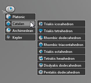
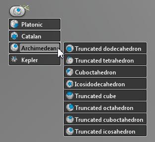
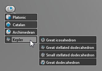
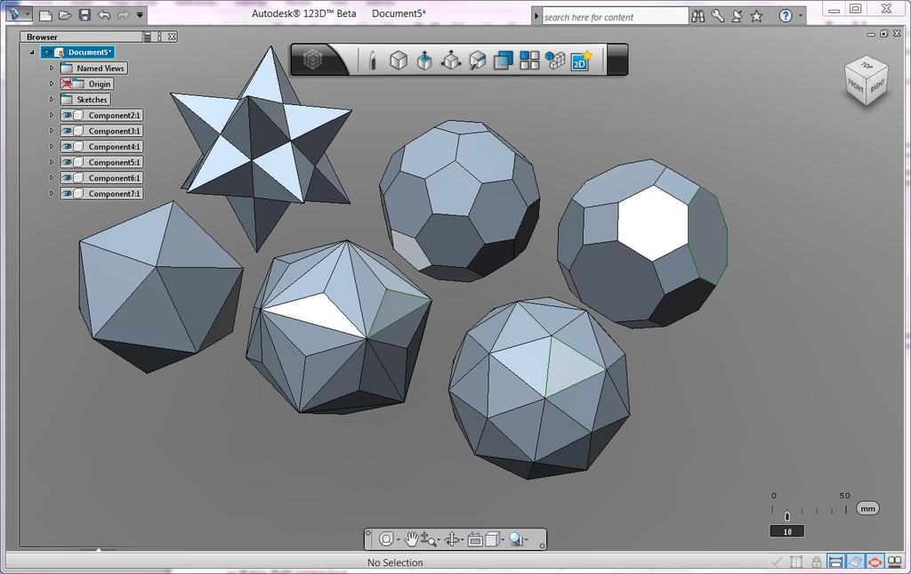
19 Placing the primitives is quite straight forward, however here are a few further details on some of them. Pyramid: The default set pyramid base is 3 sided, but you can change this to 4, 5, etc., by entering new values in the field that dispalys the number of sides (to access that field, click on Tab key while dragging the base shape). After a new value is entered, the number of sides changes and then you drag the height. By changing the numbers of the base you can get any of the shapes in the following figure. Polyhedra Quite an amazing array of really complex shapes can be made with few clicks, using the Polyhedra tool. 123D supports 4 base types of Polyhedrons: Platonic, Catalan, Archimedes and Kepler, each of which contains subshapes. Autodesk 123D Beta 5 19
20 20


21 Directly Edit the Model Geometry After you have created the initial solid model for a design, you can resize and reshape the design by directly manipulating that solid body. The resizing and reshaping is done by using the Press/Pull, Move, or Edge Edit command. You use the Press/Pull command to change the size of a part by pulling a part face away from the part or pushing the face into the part. By doing this edit, you end up offsetting the face from its initial position to a new location. Press/Pull can invoke two additional commands: Fillet and Extrude. If, while in the Press/Pull command, you select a model edge, a fillet starts on that edge. If you select a sketch closed profile, an extrude starts on that profile. The Move command enables you to move or rotate model geometry or entire components. When you move or rotate model geometry, you can change the position and orientation of one or more faces or edges. In the following illustration, two views of a cylinder with a taper are shown during and after the moving of the top circular edge. Autodesk 123D Beta 5 21


22 You start the Press/Pull and Move commands from the Press/Pull category of the command toolbar, the marking menu, or in-canvas menu. The Move command is also accessible from the Browser and upon selecting any component in it Command Toolbar > Create In Canvas Shortcut Menu Marking Menu You can use the Edit Edge command to reshape a model by changing the position of points along an edge. After you select an edge to edit, points display on that edge. The number of points along a selected edge depends on the shape of the edge. Additional points can be added at any location along the edge. Through the use of this command, you can easily create very complex model shapes. In the following illustration, the shape of the model was dramatically changed just by editing two edges that were created by splitting the flat face with a rectangle shape. If the model shape you are modifying is symmetric, prior to editing an edge you can enable and define a Symmetry plane. After defining the symmetry plane, as you edit one edge the same edit occurs to the symmetrical edge. 22


 and finally pick (recommended to do from the browser) first the body that will be affected, and")
23 You start the Edit Edge command from the Freeform category of the command toolbar or the in-canvas menu. Command Toolbar > Create In-Canvas Menu Combine Another way to arrive to desired forms is combining different bodies and parts. This is done using the Combine toolset that you can access from the context menu, right click, under the Solid features. The combine command will prompt a glyph, that when expanded offers three Boolean actions: Join, Cut, and Intersect. The workflow is to first select the command (Combine), than pick the glyph and select which type of combine (Join, Intersect or Cut) and finally pick (recommended to do from the browser) first the body that will be affected, and second the one that will perform the action. You finalize the action with OK on the right click. In the example below, the action of cut is performed, first picking the Box and then the Torus and finish with OK. Autodesk 123D Beta 5 23


24 If you switched the order of selection and first picked on the torus and then on the box, the result would have been a torus sliced in its half by the box. Using Dimensions or Assembly Constraints to Incorporate Design Intent After you have created model geometry or multiple components in a design, you have the option of creating and including additional design intent. The design intent can be in the form of dimensions or assembly constraints. Dimensions are added using the Dimension command and constraints are added using the Assemble command. You start the Dimension or Assemble command from the Design Intent category of the command toolbar or the shortcut menu. Command Toolbar > Design Intent In-Canvas Shortcut Menu Dimensions that are added between geometry in the same solid model can drive the size of that model geometry. When you first add a dimension to a model, that dimension is initially driven by the selected geometry. This means that the dimension value is a reflection of the current distance or angle. After you have added a dimension, 24


25 you can use that dimension to drive the geometry size or position by editing the dimension value. To edit the value of a dimension, with no command active you just double-click the current dimension value and enter the required value. A dimension that has been edited is automatically locked so it continues to drive the geometry. When a dimension is locked, the size or angle of the dimensioned geometry will remain that value even if you attempt to do a direct edit of the geometry. In the following illustration, the linear dimension for the material thickness is shown being edited and the results of that edit. The value for a locked dimension displays in bold text. A locked dimension also displays a Lock glyph when the cursor is positioned over that dimension. An Unlock glyph indicates the dimension is not locked and is therefore driven by the geometry. By clicking the glyph, you can toggle the lock for that dimension. If you add a dimension between separate components in a design, that dimension will only be a driven dimension. When a dimension is added to a model, it is placed on a flat plane based on the selected geometry. That flat plane is called an Annotation Plane. Depending on what geometry is selected to dimension, there may be multiple Autodesk 123D Beta 5 25


26 planes that dimension can be created in. Prior to setting the position of the dimension value, you cycle through the available planes by pressing TAB. Each annotation plane that is created for a dimension is added to the browser under Annotation Planes. These browser entries enable you to toggle on and off the visibility of the dimensions and delete all dimensions on that annotation plane. When your design consists of multiple parts, you can incorporate your intention of how the components relate to each other by adding assembly constraints. An assembly constraint is a defined relationship between the geometry on one component and the geometry on another component. The general workflow is to start the Assemble command, select the geometry on the component you want to move, select geometry on the second component, ensure the required constraint type is active, and enter the offset distance or angle. The types of assembly constraint relationships are mate, flush, angle, align, center, and tangent. The type of constraint that will be available to use will depend on the geometry you select. The available constraining options will be different if you select flat faces on both components versus selecting circular edges on both components. To change the type of constraint to use, after selecting the geometry on one or both components, you select the constraint type from the in canvas list. The offset distance or angle value is also entered in canvas. Each assembly constraint you add is listed in the browser under Assembly Constraints. The two components that were selected are listed below the constraint. By right-clicking the constraint in the browser, you access the options for editing, suppressing, and deleting the constraint. 26
, STEP (only up to version 7.0), SAT, IGES, OBJ, SKP, 123C, STL, DXF (3D).")
 123D can read them, display them, resize and reposition but not geometrically edit them.")
27 Import You can incorporate other designs that you already have, that you downloaded for free from 123Dapp.com or elsewhere, or purchased. 123D supports import of the following file types: 123D, DWG (3D), STEP (only up to version 7.0), SAT, IGES, OBJ, SKP, 123C, STL, DXF (3D). It is important to understand that 123D is a solid modeler and will only be able to fully edit imported models as long as they are solid models. If the imported models are meshes (usually coming from SketchUp, Blender, Max, Maya, Modo etc) 123D can read them, display them, resize and reposition but not geometrically edit them. The purpose of those models would be either to serve as scenes and props for enhancing the environment for visualization or to add to the 123D native model for the purposes of 3D printing. 123D currently does not read surfaces. The base of the ring below was made natively in 123D and the sheep is a mesh model, downloaded from 123Dapp.com, placed on top of the ring, resized and positioned and then all together saved as STL to be sent to a 3D printer. Autodesk 123D Beta 5 27

 You can select objects in the")

28 Document your Design Aside from the dimension tools that help drive your designs as well as document them, 123D has ways to measure quantity, mass, volume, perimeter etc. of the shapes/materials used in your design. Measure The Measure command provides two important functions: Provide geometry information (distance, angle, area, and so on). Populate input boxes with measurement. Access the measure command in the fly out of any input box (right click anywhere in the canvas, you will find Measure in the list) You can select objects in the browser or in the graphics window when using measure. You can also use filters to control which geometry types are eligible for selection. The filter appears on the flyout menu after the Measure command is invoked. Depending on what you selected (a face, an entire body etc.) you can get different valuable information about the size, volume, mass, perimeters of the selected entities. These values can be copied to the clipboard and pasted elsewhere for reuse. 28

29 Share Your Designs After you have completed your design, you may want to share it with others so they can view it, send it to a service so one or more parts can be machined or rapid prototyped, or print it for your use. Each of these tasks is initiated from the Application menu. Image To create an image file of what you see in canvas, go to the Application menu and click Publish > Image. You then specify the type of image file you want to create and the image setting to use. Save 3D files By clicking Save As, you have the option of saving the design file as a different file type. You can save to the following file formats: native 123D, STL, SAT, DWG, DXF, IGES, VMRL or STEP file. For 3D printing, you will need to select the STL or VMRL file type. (STL is the de facto standard format for 3D printing; VMRL serves as a file format for color 3D printing, something STL format does not do). When you use the Save As option to save a design file as an STL file, the entire contents of that file are saved to that STL file. If your design consists of multiple components and you want to save just one component that is in a design of multiple components to an STL file, in the browser right-click that component. In the shortcut menu click Save As. You then set the save as file type to STL. The current STL export is ASCII export. While 123D reads both the ASCII and binary version of STL, it currently only exports in ASCII. Note: STL saves both 123D natively created geometry as well as any imported mesh geometry. While the STL output of model exclusively modeled in 123D is watertight solid for 3d printing, when a mesh has been imported into a 123D file, the resulting STL might not be 3D printing ready if the mesh import had issues such as gaps or water tightness. Publish 2D Sheets Autodesk 123D Beta 5 29

30 To communicate designs to others, document design or connect with some fabbing machines, one needs to create 2D vector drawings of the designs. 123D supports creation of 2D sheets for documentation drawings and for printing. The current capabilities of this first version of the 2D sheet tool include: Creation of sheets in various standard sizes Ability to create multiple sheets (all appear as separate nodes in the browser) Placing standard views on the sheet (Top, Bottom, Left, Right, Front, Back, and Isometric views) Setting various scales per model view Setting graphic appearance per view Edit properties of each view after they have been placed Currently 123D does not support adding any annotations or text. The proposed workflow for creating final 2D sheets is to create a sheet in 123D and once the sheets is ready and is active, publish it using the Publish function to either AutoCAD WS or to AutoCAD DWG where you can add text, dimensions etc. (to clarify: Save AS DWG saves only 3D entities. Publish to AutoCAD DWG publishes the 2D layout sheet). You have two choices for workflows of finalizing 2D sheets: Publish 2D sheet to AutoCAD WS or DWG: Publish to AutoCAD WS (a FREE online view, edit and share drafting and documentation service available at where one can then add Text, Dimensions, annotations, make a sheet layout with lines, etc. (Be sure, once it is published to AutoCAD WS, in the AutoCAD WS environment to switch to View tab, Layouts and there change the view to 2D Layout sheets so to see the exact sheet you made in 123D.) You can also simply publish to AutoCAD DWG which will save a 2D DWG file on your desktop and then use any 2D CAD editor to add text, dimensions etc. or manually upload later to AutoCAD WS 30
31 Enjoy using Autodesk 123D Beta5! Autodesk, AutoCAD and 123D are registered trademarks or trademarks of Autodesk, Inc., and/or its subsidiaries and/or affiliates in the USA and/or other countries. All other brand names, product names, or trademarks belong to their respective holders. Autodesk reserves the right to alter product and services offerings, and specifications and pricing at any time without notice, and is not responsible for typographical or graphical errors that may appear in this document Autodesk, Inc. All rights reserved. Autodesk 123D Beta 5 31
Autodesk Fusion 360 Training: The Future of Making Things Attendee Guide
 Autodesk Fusion 360 Training: The Future of Making Things Attendee Guide Abstract After completing this workshop, you will have a basic understanding of editing 3D models using Autodesk Fusion 360 TM to
3D Design with 123D Design
 3D Design with 123D Design Introduction: 3D Design involves thinking and creating in 3 dimensions. x, y and z axis Working with 123D Design 123D Design is a 3D design software package from Autodesk. A
3D Modeling and Design Glossary - Beginner
 3D Modeling and Design Glossary - Beginner Align: to place or arrange (things) in a straight line. To use the Align tool, select at least two objects by Shift left-clicking on them or by dragging a box
Autodesk Inventor Design Exercise 2: F1 Team Challenge Car Developed by Tim Varner Synergis Technologies
 Autodesk Inventor Design Exercise 2: F1 Team Challenge Car Developed by Tim Varner Synergis Technologies Tim Varner - 2004 The Inventor User Interface Command Panel Lists the commands that are currently
This is the opening view of blender.
 This is the opening view of blender. Note that interacting with Blender is a little different from other programs that you may be used to. For example, left clicking won t select objects on the scene,
Parametric Modeling. With. Autodesk Inventor. Randy H. Shih. Oregon Institute of Technology SDC PUBLICATIONS
 Parametric Modeling With Autodesk Inventor R10 Randy H. Shih Oregon Institute of Technology SDC PUBLICATIONS Schroff Development Corporation www.schroff.com www.schroff-europe.com 2-1 Chapter 2 Parametric
SOLIDWORKS 2016: A Power Guide for Beginners and Intermediate Users
 SOLIDWORKS 2016: A Power Guide for Beginners and Intermediate Users The premium provider of learning products and solutions www.cadartifex.com Table of Contents Dedication... 3 Preface... 15 Part 1. Introducing
1.1: Introduction to Fusion 360
 .: Introduction to Fusion 360 Fusion 360 is a cloud- based CAD/CAM tool for collaborative product development. The tools in Fusion enable exploration and iteration on product ideas and collaboration within
Autodesk Fusion 360: Model. Overview. Modeling techniques in Fusion 360
 Overview Modeling techniques in Fusion 360 Modeling in Fusion 360 is quite a different experience from how you would model in conventional history-based CAD software. Some users have expressed that it
Autodesk Inventor - Basics Tutorial Exercise 1
 Autodesk Inventor - Basics Tutorial Exercise 1 Launch Inventor Professional 2015 1. Start a New part. Depending on how Inventor was installed, using this icon may get you an Inch or Metric file. To be
Tips and tricks. AutoCAD 2010
 Tips and tricks AutoCAD 2010 Parametric Drawing Powerful new parametric drawing functionality in AutoCAD 2010 enables you to dramatically increase productivity by constraining drawing objects based on
SOLIDWORKS 2016 and Engineering Graphics
 SOLIDWORKS 2016 and Engineering Graphics An Integrated Approach Randy H. Shih SDC PUBLICATIONS Better Textbooks. Lower Prices. www.sdcpublications.com Powered by TCPDF (www.tcpdf.org) Visit the following
SolidWorks 2013 and Engineering Graphics
 SolidWorks 2013 and Engineering Graphics An Integrated Approach Randy H. Shih SDC PUBLICATIONS Schroff Development Corporation Better Textbooks. Lower Prices. www.sdcpublications.com Visit the following
3D ModelingChapter1: Chapter. Objectives
 Chapter 1 3D ModelingChapter1: The lessons covered in this chapter familiarize you with 3D modeling and how you view your designs as you create them. You also learn the coordinate system and how you can
An Introduction to Autodesk Inventor 2012 and AutoCAD Randy H. Shih SDC PUBLICATIONS. Schroff Development Corporation
 An Introduction to Autodesk Inventor 2012 and AutoCAD 2012 Randy H. Shih SDC PUBLICATIONS www.sdcpublications.com Schroff Development Corporation Visit the following websites to learn more about this book:
Lesson 1 Parametric Modeling Fundamentals
 1-1 Lesson 1 Parametric Modeling Fundamentals Create Simple Parametric Models. Understand the Basic Parametric Modeling Process. Create and Profile Rough Sketches. Understand the "Shape before size" approach.
Solid Modeling: Part 1
 Solid Modeling: Part 1 Basics of Revolving, Extruding, and Boolean Operations Revolving Exercise: Stepped Shaft Start AutoCAD and use the solid.dwt template file to create a new drawing. Create the top
Autodesk Inventor 2019 and Engineering Graphics
 Autodesk Inventor 2019 and Engineering Graphics An Integrated Approach Randy H. Shih SDC PUBLICATIONS Better Textbooks. Lower Prices. www.sdcpublications.com Powered by TCPDF (www.tcpdf.org) Visit the
An Introduction to Autodesk Inventor 2010 and AutoCAD Randy H. Shih SDC PUBLICATIONS. Schroff Development Corporation
 An Introduction to Autodesk Inventor 2010 and AutoCAD 2010 Randy H. Shih SDC PUBLICATIONS Schroff Development Corporation www.schroff.com 2-1 Chapter 2 Parametric Modeling Fundamentals Create Simple Extruded
An Introduction to Autodesk Inventor 2013 and AutoCAD
 An Introduction to Autodesk Inventor 2013 and AutoCAD 2013 Randy H. Shih SDC PUBLICATIONS Schroff Development Corporation Better Textbooks. Lower Prices. www.sdcpublications.com Visit the following websites
Parametric Modeling with UGS NX 4
 Parametric Modeling with UGS NX 4 Randy H. Shih Oregon Institute of Technology SDC PUBLICATIONS Schroff Development Corporation www.schroff.com www.schroff-europe.com 2-1 Chapter 2 Parametric Modeling
COMPUTER AIDED ARCHITECTURAL GRAPHICS FFD 201/Fall 2013 HAND OUT 1 : INTRODUCTION TO 3D
 COMPUTER AIDED ARCHITECTURAL GRAPHICS FFD 201/Fall 2013 INSTRUCTORS E-MAIL ADDRESS OFFICE HOURS Özgür Genca ozgurgenca@gmail.com part time Tuba Doğu tubadogu@gmail.com part time Şebnem Yanç Demirkan sebnem.demirkan@gmail.com
AUTODESK FUSION 360 Designing a RC Car Body
 AUTODESK FUSION 360 Designing a RC Car Body Abstract This project explores how to use the sculpting tools available in Autodesk Fusion 360 Ultimate to design the body of a RC car. John Helfen john.helfen@autodesk.com
SpaceClaim Professional The Natural 3D Design System. Advanced Technology
 SpaceClaim Professional The Natural 3D Design System SpaceClaim Professional is the 3D productivity tool for engineers who contribute to the design and manufacture of mechanical products across a broad
Parametric Modeling with. Autodesk Fusion 360. First Edition. Randy H. Shih SDC. Better Textbooks. Lower Prices.
 Parametric Modeling with Autodesk Fusion 360 First Edition Randy H. Shih SDC PUBLICATIONS Better Textbooks. Lower Prices. www.sdcpublications.com Powered by TCPDF (www.tcpdf.org) Visit the following websites
solidthinking Inspired Tutorials 2009 solidthinking, Inc. for Mac
 solidthinking Inspired Tutorials 2009 solidthinking, Inc. for Mac Table of Contents Quick Start Tutorials 3 Tutorial 11: Simple... Bridge 4 Tutorial 22: Desk... 12 Tutorial 33: Bookcase... 35 2 1 Quick
SolidWorks Implementation Guides. User Interface
 SolidWorks Implementation Guides User Interface Since most 2D CAD and SolidWorks are applications in the Microsoft Windows environment, tool buttons, toolbars, and the general appearance of the windows
Parametric Modeling. with. Autodesk Inventor Randy H. Shih. Oregon Institute of Technology SDC
 Parametric Modeling with Autodesk Inventor 2009 Randy H. Shih Oregon Institute of Technology SDC PUBLICATIONS Schroff Development Corporation www.schroff.com Better Textbooks. Lower Prices. 2-1 Chapter
Autodesk Fusion 360: Introduction. Overview
 Overview Fusion 360 is a cloud-based CAD/CAM tool for collaborative product development. The tools in Fusion enable exploration and iteration on product ideas and collaboration within a product development
Chapter 2 Parametric Modeling Fundamentals
 2-1 Chapter 2 Parametric Modeling Fundamentals Create Simple Extruded Solid Models Understand the Basic Parametric Modeling Procedure Create 2-D Sketches Understand the "Shape before Size" Approach Use
solidthinking Environment...1 Modeling Views...5 Console...13 Selecting Objects...15 Working Modes...19 World Browser...25 Construction Tree...
 Copyright 1993-2009 solidthinking, Inc. All rights reserved. solidthinking and renderthinking are trademarks of solidthinking, Inc. All other trademarks or service marks are the property of their respective
User Guide. for. JewelCAD Professional Version 2.0
 User Guide Page 1 of 121 User Guide for JewelCAD Professional Version 2.0-1 - User Guide Page 2 of 121 Table of Content 1. Introduction... 7 1.1. Purpose of this document... 7 2. Launch JewelCAD Professional
Chapter 2 Parametric Modeling Fundamentals
 2-1 Chapter 2 Parametric Modeling Fundamentals Create Simple Extruded Solid Models Understand the Basic Parametric Modeling Procedure Create 2-D Sketches Understand the Shape before Size Approach Use the
Exercise Guide. Published: August MecSoft Corpotation
 VisualCAD Exercise Guide Published: August 2018 MecSoft Corpotation Copyright 1998-2018 VisualCAD 2018 Exercise Guide by Mecsoft Corporation User Notes: Contents 2 Table of Contents About this Guide 4
Autodesk Inventor 2018
 Learning Autodesk Inventor 2018 Modeling, Assembly and Analysis Randy H. Shih SDC PUBLICATIONS Better Textbooks. Lower Prices. www.sdcpublications.com Powered by TCPDF (www.tcpdf.org) Visit the following
SWITCHING FROM SKETCHUP TO VECTORWORKS
 SWITCHING FROM SKETCHUP TO VECTORWORKS INTRODUCTION There are a lot of 3D modeling software programs to choose from and each has its own strengths and weaknesses. For architects, flexibility and ease of
A Guide to Autodesk Maya 2015
 A Guide to Autodesk Maya 2015 Written by Mitchell Youngerman Table of Contents Layout of Toolbars...pg 1 Creating Objects...pg 2 Selecting & Deselecting Objects...pg 3 Changing Perspective... pg 4 Transforming
Structural & Thermal Analysis Using the ANSYS Workbench Release 12.1 Environment
 ANSYS Workbench Tutorial Structural & Thermal Analysis Using the ANSYS Workbench Release 12.1 Environment Kent L. Lawrence Mechanical and Aerospace Engineering University of Texas at Arlington SDC PUBLICATIONS
Lesson 1: Creating T- Spline Forms. In Samples section of your Data Panel, browse to: Fusion 101 Training > 03 Sculpt > 03_Sculpting_Introduction.
 3.1: Sculpting Sculpting in Fusion 360 allows for the intuitive freeform creation of organic solid bodies and surfaces by leveraging the T- Splines technology. In the Sculpt Workspace, you can rapidly
Module 1: Basics of Solids Modeling with SolidWorks
 Module 1: Basics of Solids Modeling with SolidWorks Introduction SolidWorks is the state of the art in computer-aided design (CAD). SolidWorks represents an object in a virtual environment just as it exists
Rhinoceros NURBS modeling for Windows. Version 1.0 Training Manual Level 1
 Rhinoceros NURBS modeling for Windows Version 1.0 Training Manual Level 1 rhinolevel 1.doc Robert McNeel & Associates 1997. All Rights Reserved. Printed in U.S.A. Copyright by Robert McNeel & Associates.
Introduction to Solid Modeling Parametric Modeling. Mechanical Engineering Dept.
 Introduction to Solid Modeling Parametric Modeling 1 Why draw 3D Models? 3D models are easier to interpret. Simulation under real-life conditions. Less expensive than building a physical model. 3D models
Tools for Design. with VEX Robot Kit: Randy H. Shih Oregon Institute of Technology SDC PUBLICATIONS
 Tools for Design with VEX Robot Kit: AutoCAD 2011 and Autodesk Inventor 2011 2D Drawing 3D Modeling Hand Sketching Randy H. Shih Oregon Institute of Technology INSIDE: SUPPLEMENTAL FILES ON CD SDC PUBLICATIONS
INTRODUCTION TO 123D DESIGN
 INTRODUCTION TO 123D DESIGN *Dear users, please feel free to download this Help pdf and print it for your personal use. Help document may get updated and you may find the document on http://www.123dapp.com/design.
NURBS modeling for Windows. Training Manual Level 1
 NURBS modeling for Windows Training Manual Level 1 Rhino Level 1 Training 2nd Ed.doc Robert McNeel & Associates 1997-2000 All Rights Reserved. Printed in U.S.A. Copyright by Robert McNeel & Associates.
Learning Autodesk Inventor 2014
 Learning Autodesk Inventor 2014 Modeling, Assembly and Analysis Randy H. Shih SDC P U B L I C AT I O N S Better Textbooks. Lower Prices. www.sdcpublications.com Visit the following websites to learn more
Engineering Drawing II
 Instructional Unit Basic Shading and Rendering -Basic Shading -Students will be able -Demonstrate the ability Class Discussions 3.1.12.B, -Basic Rendering to shade a 3D model to apply shading to a 3D 3.2.12.C,
Parametric Modeling with NX 12
 Parametric Modeling with NX 12 NEW Contains a new chapter on 3D printing Randy H. Shih SDC PUBLICATIONS Better Textbooks. Lower Prices. www.sdcpublications.com Powered by TCPDF (www.tcpdf.org) Visit the
Google SketchUp. and SketchUp Pro 7. The book you need to succeed! CD-ROM Included! Kelly L. Murdock. Master SketchUp Pro 7 s tools and features
 CD-ROM Included! Free version of Google SketchUp 7 Trial version of Google SketchUp Pro 7 Chapter example files from the book Kelly L. Murdock Google SketchUp and SketchUp Pro 7 Master SketchUp Pro 7 s
Structural & Thermal Analysis using the ANSYS Workbench Release 11.0 Environment. Kent L. Lawrence
 ANSYS Workbench Tutorial Structural & Thermal Analysis using the ANSYS Workbench Release 11.0 Environment Kent L. Lawrence Mechanical and Aerospace Engineering University of Texas at Arlington SDC PUBLICATIONS
Autodesk Inventor 2018
 Parametric Modeling with Autodesk Inventor 2018 NEW Contains a new chapter on 3D printing Randy H. Shih SDC PUBLICATIONS Better Textbooks. Lower Prices. www.sdcpublications.com Powered by TCPDF (www.tcpdf.org)
Tools for Design. A practical guide to 2D Drawing, Sketching, 3D Parametric Modeling and Finite Element Analysis
 Tools for Design Using AutoCAD 2011, Autodesk Inventor 2011, and LEGO MINDSTORMS NXT & TETRIX A practical guide to 2D Drawing, Sketching, 3D Parametric Modeling and Finite Element Analysis INSIDE: SUPPLEMENTAL
Tools for Design. with FischerTechnik: Randy H. Shih Oregon Institute of Technology SDC PUBLICATIONS
 Tools for Design with FischerTechnik: AutoCAD 2012 and Autodesk Inventor 2012 2D Drawing 3D Modeling Hand Sketching INCLUDES: Randy H. Shih Oregon Institute of Technology AUTODESK INVENTOR PART FILES FOR
Technical Education Services
 Autodesk Fusion 360: Introduction to Parametric Modeling Course Length: 3 days Official Training Guide The Autodesk Fusion 360 Introduction to Parametric Modeling training course provides you with an understanding
SolidWorks 2½D Parts
 SolidWorks 2½D Parts IDeATe Laser Micro Part 1b Dave Touretzky and Susan Finger 1. Create a new part In this lab, you ll create a CAD model of the 2 ½ D key fob below to make on the laser cutter. Select
Modeling Basics for 3D Printing Using AutoCAD
 Modeling Basics for 3D Printing Using AutoCAD William Work CAD Manager Join us on Twitter: #AU2014 Who am I? Architect CAD Manager I am an architect and CAD manager with a firm of more than three hundred
4) Finish the spline here. To complete the spline, double click the last point or select the spline tool again.
 Finish the spline here. To complete the spline, double click the last point or select the spline tool again.") 1) Select the line tool 3) Move the cursor along the X direction (be careful to stay on the X axis alignment so that the line is perpendicular) and click for the second point of the line. Type 0.5 for
1) Select the line tool 3) Move the cursor along the X direction (be careful to stay on the X axis alignment so that the line is perpendicular) and click for the second point of the line. Type 0.5 for
ARCHITECTURE & GAMES. A is for Architect Simple Mass Modeling FORM & SPACE. Industry Careers Framework. Applied. Getting Started.
 A is for Architect Simple Mass Modeling One of the first introductions to form and space usually comes at a very early age. As an infant, you might have played with building blocks to help hone your motor
SolidWorks Intro Part 1b
 SolidWorks Intro Part 1b Dave Touretzky and Susan Finger 1. Create a new part We ll create a CAD model of the 2 ½ D key fob below to make on the laser cutter. Select File New Templates IPSpart If the SolidWorks
Tools for Design. Using AutoCAD 2015 and Autodesk Inventor 2015 SDC. Hand Sketching, 2D Drawing and 3D Modeling. Randy H. Shih
 Tools for Design Using AutoCAD 2015 and Autodesk Inventor 2015 Hand Sketching, 2D Drawing and 3D Modeling Randy H. Shih SDC PUBLICATIONS Better Textbooks. Lower Prices. www.sdcpublications.com Powered
Parametric Modeling with SOLIDWORKS 2017
 Parametric Modeling with SOLIDWORKS 2017 NEW Contains a new chapter on 3D printing Covers material found on the CSWA exam Randy H. Shih Paul J. Schilling SDC PUBLICATIONS Better Textbooks. Lower Prices.
Lesson 5 Solid Modeling - Constructive Solid Geometry
 AutoCAD 2000i Tutorial 5-1 Lesson 5 Solid Modeling - Constructive Solid Geometry Understand the Constructive Solid Geometry Concept. Create a Binary Tree. Understand the basic Boolean Operations. Create
Module 2 Review. Assemblies and Rendering. Why Use Assemblies. Assemblies - Key Concepts. Sketch Planes Sketched Features.
 Module 2 Review Assemblies and Rendering EF 101 Modules 3.1, 3.2 Sketch Planes Sketched Features Extrude, Revolve Placed Features Hole, Fillet, Chamfer, Shell, Rect. Pattern Drawing Views Base, Ortho,
3 Polygonal Modeling. Getting Started with Maya 103
 3 Polygonal Modeling In Maya, modeling refers to the process of creating virtual 3D surfaces for the characters and objects in the Maya scene. Surfaces play an important role in the overall Maya workflow
SOLIDWORKS Parametric Modeling with SDC. Covers material found on the CSWA exam. Randy H. Shih Paul J. Schilling
 Parametric Modeling with SOLIDWORKS 2015 Covers material found on the CSWA exam Randy H. Shih Paul J. Schilling SDC PUBLICATIONS Better Textbooks. Lower Prices. www.sdcpublications.com Powered by TCPDF
AutoCAD 2013 Tutorial - Second Level: 3D Modeling
 AutoCAD 2013 Tutorial - Second Level: 3D Modeling Randy H. Shih SDC PUBLICATIONS Schroff Development Corporation Better Textbooks. Lower Prices. www.sdcpublications.com Visit the following websites to
Parametric Modeling with SolidWorks
 Parametric Modeling with SolidWorks 2012 LEGO MINDSTORMS NXT Assembly Project Included Randy H. Shih Paul J. Schilling SDC PUBLICATIONS Schroff Development Corporation Better Textbooks. Lower Prices. www.sdcpublications.com
Autodesk Inventor 2016 Learn by doing. Tutorial Books
 Autodesk Inventor 2016 Learn by doing Tutorial Books Copyright 2015 Kishore This book may not be duplicated in any way without the express written consent of the publisher, except in the form of brief
Inventor 201. Work Planes, Features & Constraints: Advanced part features and constraints
 Work Planes, Features & Constraints: 1. Select the Work Plane feature tool, move the cursor to the rim of the base so that inside and outside edges are highlighted and click once on the bottom rim of the
Parametric Modeling Design and Modeling 2011 Project Lead The Way, Inc.
 Parametric Modeling Design and Modeling 2011 Project Lead The Way, Inc. 3D Modeling Steps - Sketch Step 1 Sketch Geometry Sketch Geometry Line Sketch Tool 3D Modeling Steps - Constrain Step 1 Sketch Geometry
Feature-Based Modeling and Optional Advanced Modeling. ENGR 1182 SolidWorks 05
 Feature-Based Modeling and Optional Advanced Modeling ENGR 1182 SolidWorks 05 Today s Objectives Feature-Based Modeling (comprised of 2 sections as shown below) 1. Breaking it down into features Creating
Autodesk Inventor 6 Essentials Instructor Guide Chapter Four: Creating Placed Features Chapter Outline This chapter provides instruction on the follow
 Chapter Four: Creating Placed Features Chapter Outline This chapter provides instruction on the following topics and provides exercises for students to practice their skills. Day Two Topic: How to create
COMPUTER AIDED DESIGN CURRICULLOM RHINO BASED 3D DESIGN
 COMPUTER AIDED DESIGN CURRICULLOM RHINO BASED 3D DESIGN S.no. CONTENTS Page no S. no. CONTENTS PAGE no. 1. Introduction 1 2. Necessary of Rhino in Designing 2 3. Working with 3D Models 3 4. Object Types
Autodesk Conceptual Design Curriculum 2011 Student Workbook Unit 2: Parametric Exploration Lesson 1: Parametric Modeling
 Autodesk Conceptual Design Curriculum 2011 Student Workbook Unit 2: Parametric Exploration Lesson 1: Parametric Modeling Overview: Parametric Modeling In this lesson, you learn the basic principles of
SWITCHING FROM RHINO TO VECTORWORKS
 SWITCHING FROM RHINO TO VECTORWORKS INTRODUCTION There are a lot of 3D modeling software programs to choose from and each has its own strengths and weaknesses. For architects, flexibility and ease of use
Tutorial Second Level
 AutoCAD 2018 Tutorial Second Level 3D Modeling Randy H. Shih SDC PUBLICATIONS Better Textbooks. Lower Prices. www.sdcpublications.com Powered by TCPDF (www.tcpdf.org) Visit the following websites to learn
StickFont Editor v1.01 User Manual. Copyright 2012 NCPlot Software LLC
 StickFont Editor v1.01 User Manual Copyright 2012 NCPlot Software LLC StickFont Editor Manual Table of Contents Welcome... 1 Registering StickFont Editor... 3 Getting Started... 5 Getting Started...
Chapter 4 Feature Design Tree
 4-1 Chapter 4 Feature Design Tree Understand Feature Interactions Use the FeatureManager Design Tree Modify and Update Feature Dimensions Perform History-Based Part Modifications Change the Names of Created
Introduction to SolidWorks Basics Materials Tech. Wood
 Introduction to SolidWorks Basics Materials Tech. Wood Table of Contents Table of Contents... 1 Book End... 2 Introduction... 2 Learning Intentions... 2 Modelling the Base... 3 Modelling the Front... 10
Tools for Design. Autodesk Inventor 2017 SDC. Hand Sketching, 2D Drawing and 3D Modeling. Randy H. Shih
 Tools for Design Using AutoCAD 2017 and Autodesk Inventor 2017 Hand Sketching, 2D Drawing and 3D Modeling Randy H. Shih SDC PUBLICATIONS Better Textbooks. Lower Prices. www.sdcpublications.com Powered
Spring 2011 Workshop ESSENTIALS OF 3D MODELING IN RHINOCEROS February 10 th 2011 S.R. Crown Hall Lower Core Computer Lab
 [1] Open Rhinoceros. PART 1 INTRODUCTION [4] Click and hold on the Boundary Lines in where they form a crossing and Drag from TOP RIGHT to BOTTOM LEFT to enable only the PERSPECTIVE VIEW. [2] When the
Revit Architecture 2015 Basics
 Revit Architecture 2015 Basics From the Ground Up Elise Moss Authorized Author SDC P U B L I C AT I O N S Better Textbooks. Lower Prices. www.sdcpublications.com Powered by TCPDF (www.tcpdf.org) Visit
Module 8A: Creating a Sheet Metal Part & Flat Pattern Wrapping the 3D Space of a Polyhedron
 1 Module 8A: Creating a Sheet Metal Part & Flat Pattern Wrapping the 3D Space of a Polyhedron In this Module, we will learn how to create a sheet metal part wrapping a polyhedron based on an octagonal
Solid surface modeling in AutoCAD
 Solid surface modeling in AutoCAD Introduction into 3D modeling Managing views of 3D model Coordinate Systems 1 3D model advantages ability to view the whole model looking inside the model collision checking
Design a Simple Fan in 123D Design
 Design a Simple Fan in 123D Design Learn to use 123D Design to make and print this simple fan. 123D Design is a free, powerful, yet simple 3D creation and editing tool. It allows you to design and build
The Rectangular Problem
 C h a p t e r 2 The Rectangular Problem In this chapter, you will cover the following to World Class standards: The tools for simple 2D Computer Aided Drafting (CAD) The Command Line and the Tray The Line
BobCAD CAM V25 4 Axis Standard Posted by Al /09/20 22:03
 BobCAD CAM V25 4 Axis Standard Posted by Al - 2012/09/20 22:03 Many BobCAD CAM clients that run a 4 axis have requested to work directly with Solids or STL files. In the past we only offered 4 axis indexing
Acknowledgement INTRODUCTION
 Submitted by: 1 Acknowledgement INTRODUCTION Computers are increasingly being used for doing engineering drawings and graphics work because computers allow the graphics designer or the draughtsman to change
Lesson 17 Shell, Reorder, and Insert Mode
 Lesson 17 Shell, Reorder, and Insert Mode Figure 17.1 Oil Sink OBJECTIVES Master the use of the Shell Tool Reorder features Insert a feature at a specific point in the design order Create a Hole Pattern
Module 4A: Creating the 3D Model of Right and Oblique Pyramids
 Inventor (5) Module 4A: 4A- 1 Module 4A: Creating the 3D Model of Right and Oblique Pyramids In Module 4A, we will learn how to create 3D solid models of right-axis and oblique-axis pyramid (regular or
Modeling a Gear Standard Tools, Surface Tools Solid Tool View, Trackball, Show-Hide Snaps Window 1-1
 Modeling a Gear This tutorial describes how to create a toothed gear. It combines using wireframe, solid, and surface modeling together to create a part. The model was created in standard units. To begin,
Tips & Techniques in Autodesk Inventor 2013/2014 PLTW - Wisconsin Dec. 10, 2013
 Tips & Techniques in Autodesk Inventor 2013/2014 PLTW - Wisconsin Dec. 10, 2013 Dan Banach Autodesk Inc. Dataset https://www.dropbox.com/sh/scpc4lkk94lmq8n/ydbxbxemet Instructors & students register for
Input CAD Solid Model Assemblies - Split into separate Part Files. DXF, IGES WMF, EMF STL, VDA, Rhino Parasolid, ACIS
 General NC File Output List NC Code Post Processor Selection Printer/Plotter Output Insert Existing Drawing File Input NC Code as Geometry or Tool Paths Input Raster Image Files Report Creator and Designer
Lecture 4, 5/27/2017, Rhino Interface an overview
 數字建築與城市设计 Spring 2017 Lecture 4, 5/27/2017, Rhino Interface an overview Copyright 2017, Chiu-Shui Chan. All Rights Reserved. This lecture concentrates on the use of tools, 3D solid modeling and editing
Advances in MicroStation 3D
 MW1HC515 Advances in MicroStation 3D Hands-on class sponsored by the Bentley Institute Presenter: Sam Hendrick, Senior MicroStation Product Consultant Bentley Systems, Incorporated 685 Stockton Drive Exton,
AutoCAD for Engineers and Designers, 21st Edition. (3D and Advanced)
") AutoCAD 2015 for Engineers and Designers, 21st Edition (3D and Advanced) CADCIM Technologies 525 St. Andrews Drive Schererville, IN 46375, USA (www.cadcim.com) Contributing Author Sham Tickoo Professor
AutoCAD 2015 for Engineers and Designers, 21st Edition (3D and Advanced) CADCIM Technologies 525 St. Andrews Drive Schererville, IN 46375, USA (www.cadcim.com) Contributing Author Sham Tickoo Professor
Press the Plus + key to zoom in. Press the Minus - key to zoom out. Scroll the mouse wheel away from you to zoom in; towards you to zoom out.
 Navigate Around the Map Interactive maps provide many choices for displaying information, searching for more details, and moving around the map. Most navigation uses the mouse, but at times you may also
TRAINING SESSION Q2 2016
 There are 8 main topics in this training session which focus on the Sketch tools in IRONCAD. Content Sketch... 2 3D Scene Background Settings... 3 Creating a new empty Sketch... 4 Foam with cut out for
Assessment TESTS SLO #1 CADD 131
 CADD 131 Assessment TESTS 1- SLO #1 1. Of what does a mesh model consist? 2. What is another term for mesh models? 3. What are tessellation divisions? 4. When creating a mesh primitive, when should mesh
S206E Lecture 3, 5/15/2017, Rhino 2D drawing an overview
 Copyright 2017, Chiu-Shui Chan. All Rights Reserved. S206E057 Spring 2017 Rhino 2D drawing is very much the same as it is developed in AutoCAD. There are a lot of similarities in interface and in executing