Understanding Variability
|
|
|
- Monica Cummings
- 5 years ago
- Views:
Transcription

1 Understanding Variability Why so different?
2 Light and Optics Pinhole camera model Perspective projection Thin lens model Fundamental equation Distortion: spherical & chromatic aberration, radial distortion Reflection and Illumination: color, Lambertian and specular surfaces, Phong, BRDF Sensing Light Conversion to Digital Images Sampling Theorem Other Sensors: frequency, type,.
3 Basic Radiometry Radiometry is the part of image formation concerned with the relation among the amounts of light energy emitted from light sources, reflected from surfaces, and registered by sensors. Light Source CCD Array Optics p i n e P L(P,d) Surface
4 Lecture Assumptions Typical imaging scenario: visible light ideal lenses standard sensor (e.g. TV camera) opaque objects Goal To create 'digital' images which can be processed to recover some of the characteristics of the 3D world which was imaged.

5 Steps World Optics Sensor Signal Digitizer Digital Representation World reality Optics focus {light} from world on sensor Sensor converts {light} to {electrical energy} Signal representation of incident light as continuous electrical energy Digitizer converts continuous signal to discrete signal Digital Rep. final representation of reality in computer memory
6 Factors in Image Formation Geometry concerned with the relationship between points in the three-dimensional world and their images Radiometry concerned with the relationship between the amount of light radiating from a surface and the amount incident at its image Photometry concerned with ways of measuring the intensity of light Digitization concerned with ways of converting continuous signals (in both space and time) to digital approximations
7 Image Formation Light (Energy) Source Surface Imaging Plane Pinhole Lens World Optics Sensor Signal B&W Film Color Film TV Camera Silver Density Silver density in three color layers Electrical
8 Geometry Geometry describes the projection of: three-dimensional (3D) world two-dimensional (2D) image plane. Typical Assumptions Light travels in a straight line Optical Axis: the perpendicular from the image plane through the pinhole (also called the central projection ray) Each point in the image corresponds to a particular direction defined by a ray from that point through the pinhole. Various kinds of projections: - perspective - oblique - orthographic - isometric - spherical
9 Basic Optics Two models are commonly used:" Pin-hole camera" Optical system composed of lenses" Pin-hole is the basis for most graphics and vision" Derived from physical construction of early cameras" Mathematics is very straightforward" Thin lens model is first of the lens models" Mathematical model for a physical lens" Lens gathers light over area and focuses on image plane."
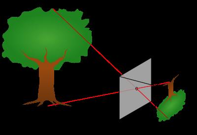
10 Pinhole Camera Model Image Plane Optical Axis f Pinhole lens World projected to 2D Image Image inverted Size reduced Image is dim No direct depth information f called the focal length of the lens Known as perspective projection


11 Pinhole camera image Amsterdam Photo by Robert Kosara,
12 Equivalent Geometry Consider case with object on the optical axis: z f More convenient with upright image: z - f Projection plane z = 0 Equivalent mathematically
13 Thin Lens Model Rays entering parallel on one side converge at focal point." Rays diverging from the focal point become parallel." f i o IMAGE PLANE LENS OPTIC AXIS 1 = THIN LENS LAW f i o
14 Coordinate System Simplified Case: Origin of world and image coordinate systems coincide Y-axis aligned with y-axis X-axis aligned with x-axis Z-axis along the central projection ray Image Coordinate System p(x,y) y (0,0,0) X Y Y World Coordinate System Z P(X,Y,Z) x (0,0) X Z
15 Perspective Projection Compute the image coordinates of p in terms of the world coordinates of P. p(x, y) y P(X,Y,Z) Z=-f x Z = 0 Z Look at projections in x-z and y-z planes
16 X-Z Projection - f Z x X By similar triangles: x f = X Z+f x = fx Z+f

17 Y-Z Projection y Y - f Z y By similar triangles: = f Y Z+f y = fy Z+f
18 Perspective Equations Given point P(X,Y,Z) in the 3D world The two equations: x = fx Z+f y = fy Z+f transform world coordinates (X,Y,Z) into image coordinates (x,y)
19 Reverse Projection Given a center of projection and image coordinates of a point, it is not possible to recover the 3D depth of the point from a single image. P(X,Y,Z) can be anywhere along this line p(x,y) All points on this line have image coordinates (x,y). In general, at least two images of the same point taken from two different locations are required to recover depth.
20 Stereo Geometry P(X,Y,Z) Object point p l Central Projection Rays p r Vergence Angle Depth obtained by triangulation Correspondence problem: p l and p r must correspond to the left and right projections of P, respectively.
21 Variability in appearance Consequences of image formation geometry for computer vision What set of shapes can an object take on? rigid non-rigid planar non-planar SIFT features Sensitivity to errors.
22 Radiometry Brightness: informal notion used to describe both scene and image brightness. Image brightness: related to energy flux incident on the image plane: IRRADIANCE Illuminance Scene brightness: brightness related to energy flux emitted (radiated) from a surface. RADIANCE luminance
23 Light and Surfaces Reflection mirrors highlights specularities Scattering Lambertian matte diffuse
24 Light sources Point source Extended source Single wavelength Multi-wavelength Uniform Non-uniform
25 Linearity of Light Linearity definition For extended sources For multiple wavelengths Across time
")
26 Light watts radiated into 4 steradians! watts d" r = d sphere d R = Point Source Radiant Intensity = d (of source) Watts/unit solid angle (steradian)

27 Irradiance Light falling on a surface from all directions. How much? d da Irradiance: power per unit area falling on a surface. d Irradiance E = d watts/m 2
28 Inverse Square Law Relationship between point source radiance (radiant intensity) and irradiance da! watts d" r d = da r 2 d E = d R: Radiant Intensity E: Irradiance d R = d r 2 d = = d r 2 E : Watts : Steradians E = R r 2

29 Surface acts as light source Radiates over a hemisphere Surface Radiance (Extended source) Surface Normal d! R: Radiant Intensity E: Irradiance L: Surface radiance da f Surface Radiance: power per unit foreshortened area emitted into a solid angle L = d da d f (watts/m 2 steradian)
30 Pseudo-Radiance Consider two definitions: Radiance: power per unit foreshortened area emitted into a solid angle Pseudo-radiance power per unit area emitted into a solid angle Why should we work with radiance rather than pseudoradiance? Only reason: Radiance is more closely related to our intuitive notion of brightness.
31 Lambertian Surfaces A particular point P on a Lambertian (perfectly matte) surface appears to have the same brightness no matter what angle it is viewed from. Piece of paper Matte paint Doesn t depend upon incident light angle. What does this say about how they emit light?
32 Lambertian Surfaces Equal Amounts of Light Observed From Each Vantage Point Theta Area of black box = 1 Area of orange box = 1/cos(Theta) Foreshortening rule.
33 Lambertian Surfaces Relative magnitude of light scattered in each direction. Proportional to cos (Theta).
34 Lambertian Surfaces Equal Amounts of Light Observed From Each Vantage Point Theta Area of black box = 1 Area of orange box = 1/cos(Theta) Foreshortening rule. Radiance = 1/cos(Theta)*cos(Theta) = 1


35 The BRDF The bidirectional reflectance distribution function.
36 Geometry Goal: Relate the radiance of a surface to the irradiance in the image plane of a simple optical system. das " Lens Diameter d : Solid angle of patch da s : Area on surface da i : Area in image i! e! dai
37 Light at the Surface E = flux incident on the surface (irradiance) = d d i = incident angle e = emittance angle g = phase angle " = surface reflectance d#! watts Incident Ray r da s " i e g N (surface normal) Emitted ray We need to determine d and da


38 Reflections from a Surface I da da = da s cos i {foreshortening effect in direction of light source} d d = flux intercepted by surface over area da da subtends solid angle d = da s cos i / r 2 d = R d = R da s cos i / r 2 E = d / da s Surface Irradiance: E = R cos i / r 2
39 Reflections from a Surface II Now treat small surface area as an emitter.because it is bouncing light into the world How much light gets reflected? Incident Ray da s i e g N (surface normal) Emitted Ray E is the surface irradiance L is the surface radiance = luminance They are related through the surface reflectance function: L s E = (i,e,g, ) May also be a function of the wavelength of the light
40 das Power Concentrated in Lens Lens Diameter d "! Image Plane! dai L = s d 2 da d s Z -f Luminance of patch (known from previous step) What is the power of the surface patch as a source in the direction of the lens? d 2 = L s da d s
41 das Through a Lens Darkly Lens Diameter d! e " In general: L is a function of the angles i and e. s Lens can be quite large Hence, must integrate over the lens solid angle to get d d = da s L s d
42 Simplifying Assumption Lens diameter is small relative to distance from patch Surface area of patch in direction of lens d = da d = da s L s s L s d d L s is a constant and can be removed from the integral Solid angle subtended by lens in direction of patch = da s cos e = Area of lens as seen from patch (Distance from lens to patch) 2 = 2 (d/2) cos (z / cos ) 2
43 Putting it Together d = da s L s d = da cos e L s s 2 (d/2) cos (z / cos ) 2 Power concentrated in lens: d d = L s da cos e cos 3 s 4 Z 2 Assuming a lossless lens, this is also the power radiated by the lens as a source.
44 das Lens Diameter d Through a Lens Darkly "! Image Plane! dai Image irradiance at da = Z -f i d da i =E i E = i L s da s 2 3 da i 4 d Z cos e cos ratio of areas
45 das Lens Diameter d Patch ratio "! Image Plane! dai Z -f The two solid angles are equal da s cos e da i cos (Z / cos ) 2 = da s cos (-f / cos ) 2 = da i cos e Z -f 2
46 The Fundamental Result Source Radiance to Image Sensor Irradiance: da s da i = cos cos e Z -f 2 E = i L s da s 2 3 da i 4 d Z cos e cos E = i L s cos cos e Z -f 2 4 d Z 2 3 cos e cos E = i L s 4 d -f 2 4 cos
47 Radiometry Final Result E = i L s 4 d -f 2 4 cos Image irradiance is a function of: Scene radiance L s Focal length of lens f Diameter of lens d f/d is often called the 'effective focal length' of the lens Off-axis angle


48 4 Cos Light Falloff Lens Center Top view shaded by height y /2 /2 /2 x
49 Limitation of Radiometry Model Surface reflection can be a function of viewing and/or illumination angle Surface normal N i g! i! e e (i,e,g,, e ) = i dl(e, ) e de(i, ) i Arbitrary reference axis may also be a function of the wavelength of the light source Assumed a point source (sky, for example, is not)
50 Lambertian Surfaces The BRDF for a Lambertian surface is a constant (i,e,g,, ) = k e i function of cos e due to the foreshortening effect k is the 'albedo' of the surface Good model for diffuse surfaces Other models combine diffuse and specular components (Phong, Torrance-Sparrow, Oren-Nayar)

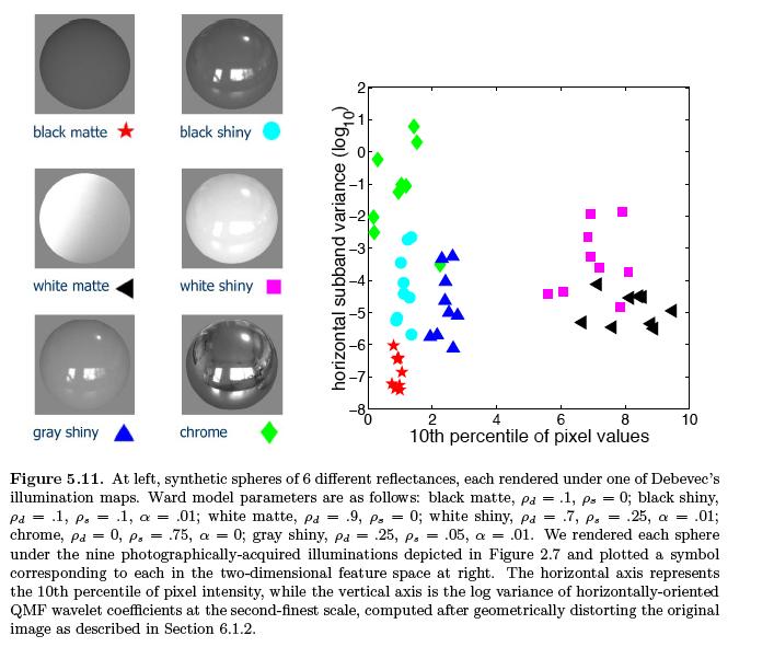
51 BRDF Ron Dror s thesis

52 Reflection parameters

53 Real World Light Variation

54 Fake Light and Real Light

55 Simple and Complex Light
56 BRDF again
57 Likelihood of material

58 Classifying Under Uncertainty

59 More Fake Light
60 Illumination Maps
61 Classification
62 Classification Continued

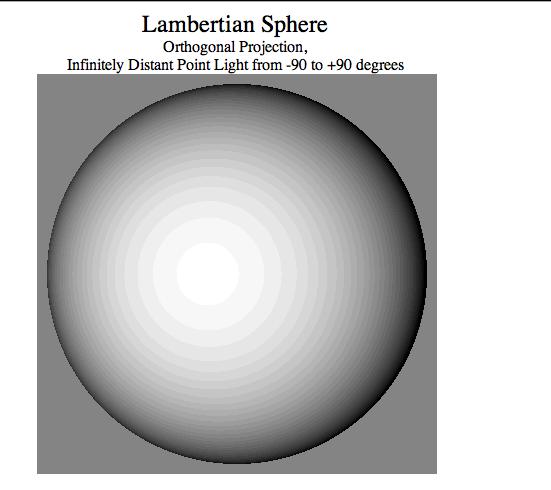
63 Lighting direction vs. Viewer direction For Lambertian surface: Viewer direction is irrelevant Lighting direction is very relevant
64
Introduction to Computer Vision. Introduction CMPSCI 591A/691A CMPSCI 570/670. Image Formation
 Introduction CMPSCI 591A/691A CMPSCI 570/670 Image Formation Lecture Outline Light and Optics Pinhole camera model Perspective projection Thin lens model Fundamental equation Distortion: spherical & chromatic
Lecture 22: Basic Image Formation CAP 5415
 Lecture 22: Basic Image Formation CAP 5415 Today We've talked about the geometry of scenes and how that affects the image We haven't talked about light yet Today, we will talk about image formation and
Capturing light. Source: A. Efros
 Capturing light Source: A. Efros Review Pinhole projection models What are vanishing points and vanishing lines? What is orthographic projection? How can we approximate orthographic projection? Lenses
Image Formation: Light and Shading. Introduction to Computer Vision CSE 152 Lecture 3
 Image Formation: Light and Shading CSE 152 Lecture 3 Announcements Homework 1 is due Apr 11, 11:59 PM Homework 2 will be assigned on Apr 11 Reading: Chapter 2: Light and Shading Geometric image formation
INFOGR Computer Graphics. J. Bikker - April-July Lecture 10: Shading Models. Welcome!
 INFOGR Computer Graphics J. Bikker - April-July 2016 - Lecture 10: Shading Models Welcome! Today s Agenda: Introduction Light Transport Materials Sensors Shading INFOGR Lecture 10 Shading Models 3 Introduction
dq dt I = Irradiance or Light Intensity is Flux Φ per area A (W/m 2 ) Φ =
 Φ =") Radiometry (From Intro to Optics, Pedrotti -4) Radiometry is measurement of Emag radiation (light) Consider a small spherical source Total energy radiating from the body over some time is Q total Radiant
Radiometry (From Intro to Optics, Pedrotti -4) Radiometry is measurement of Emag radiation (light) Consider a small spherical source Total energy radiating from the body over some time is Q total Radiant
Measuring Light: Radiometry and Cameras
 Lecture 11: Measuring Light: Radiometry and Cameras Computer Graphics CMU 15-462/15-662, Fall 2015 Slides credit: a majority of these slides were created by Matt Pharr and Pat Hanrahan Simulating a pinhole
Reflectance & Lighting
 Reflectance & Lighting Computer Vision I CSE5A Lecture 6 Last lecture in a nutshell Need for lenses (blur from pinhole) Thin lens equation Distortion and aberrations Vignetting CS5A, Winter 007 Computer
Cameras and Radiometry. Last lecture in a nutshell. Conversion Euclidean -> Homogenous -> Euclidean. Affine Camera Model. Simplified Camera Models
 Cameras and Radiometry Last lecture in a nutshell CSE 252A Lecture 5 Conversion Euclidean -> Homogenous -> Euclidean In 2-D Euclidean -> Homogenous: (x, y) -> k (x,y,1) Homogenous -> Euclidean: (x, y,
Announcements. Image Formation: Light and Shading. Photometric image formation. Geometric image formation
 Announcements Image Formation: Light and Shading Homework 0 is due Oct 5, 11:59 PM Homework 1 will be assigned on Oct 5 Reading: Chapters 2: Light and Shading CSE 252A Lecture 3 Geometric image formation
Photometric Stereo.
 Photometric Stereo Photometric Stereo v.s.. Structure from Shading [1] Photometric stereo is a technique in computer vision for estimating the surface normals of objects by observing that object under
dq dt I = Irradiance or Light Intensity is Flux Φ per area A (W/m 2 ) Φ =
 Φ =") Radiometry (From Intro to Optics, Pedrotti -4) Radiometry is measurement of Emag radiation (light) Consider a small spherical source Total energy radiating from the body over some time is Q total Radiant
Radiometry (From Intro to Optics, Pedrotti -4) Radiometry is measurement of Emag radiation (light) Consider a small spherical source Total energy radiating from the body over some time is Q total Radiant
Overview. Radiometry and Photometry. Foundations of Computer Graphics (Spring 2012)
") Foundations of Computer Graphics (Spring 2012) CS 184, Lecture 21: Radiometry http://inst.eecs.berkeley.edu/~cs184 Overview Lighting and shading key in computer graphics HW 2 etc. ad-hoc shading models,
Foundations of Computer Graphics (Spring 2012) CS 184, Lecture 21: Radiometry http://inst.eecs.berkeley.edu/~cs184 Overview Lighting and shading key in computer graphics HW 2 etc. ad-hoc shading models,
CS201 Computer Vision Lect 4 - Image Formation
 CS201 Computer Vision Lect 4 - Image Formation John Magee 9 September, 2014 Slides courtesy of Diane H. Theriault Question of the Day: Why is Computer Vision hard? Something to think about from our view
Module 5: Video Modeling Lecture 28: Illumination model. The Lecture Contains: Diffuse and Specular Reflection. Objectives_template
 The Lecture Contains: Diffuse and Specular Reflection file:///d /...0(Ganesh%20Rana)/MY%20COURSE_Ganesh%20Rana/Prof.%20Sumana%20Gupta/FINAL%20DVSP/lecture%2028/28_1.htm[12/30/2015 4:22:29 PM] Diffuse and
Radiance. Radiance properties. Radiance properties. Computer Graphics (Fall 2008)
") Computer Graphics (Fall 2008) COMS 4160, Lecture 19: Illumination and Shading 2 http://www.cs.columbia.edu/~cs4160 Radiance Power per unit projected area perpendicular to the ray per unit solid angle in
Computer Graphics (Fall 2008) COMS 4160, Lecture 19: Illumination and Shading 2 http://www.cs.columbia.edu/~cs4160 Radiance Power per unit projected area perpendicular to the ray per unit solid angle in
DD2423 Image Analysis and Computer Vision IMAGE FORMATION. Computational Vision and Active Perception School of Computer Science and Communication
 DD2423 Image Analysis and Computer Vision IMAGE FORMATION Mårten Björkman Computational Vision and Active Perception School of Computer Science and Communication November 8, 2013 1 Image formation Goal:
Radiometry and reflectance
 Radiometry and reflectance http://graphics.cs.cmu.edu/courses/15-463 15-463, 15-663, 15-862 Computational Photography Fall 2018, Lecture 16 Course announcements Homework 4 is still ongoing - Any questions?
Engineered Diffusers Intensity vs Irradiance
 Engineered Diffusers Intensity vs Irradiance Engineered Diffusers are specified by their divergence angle and intensity profile. The divergence angle usually is given as the width of the intensity distribution
EE Light & Image Formation
 EE 576 - Light & Electric Electronic Engineering Bogazici University January 29, 2018 EE 576 - Light & EE 576 - Light & The image of a three-dimensional object depends on: 1. Shape 2. Reflectance properties
Introduction to Computer Vision. Week 8, Fall 2010 Instructor: Prof. Ko Nishino
 Introduction to Computer Vision Week 8, Fall 2010 Instructor: Prof. Ko Nishino Midterm Project 2 without radial distortion correction with radial distortion correction Light Light Light! How do you recover
Announcement. Lighting and Photometric Stereo. Computer Vision I. Surface Reflectance Models. Lambertian (Diffuse) Surface.
 Surface.") Lighting and Photometric Stereo CSE252A Lecture 7 Announcement Read Chapter 2 of Forsyth & Ponce Might find section 12.1.3 of Forsyth & Ponce useful. HW Problem Emitted radiance in direction f r for incident
Lighting and Photometric Stereo CSE252A Lecture 7 Announcement Read Chapter 2 of Forsyth & Ponce Might find section 12.1.3 of Forsyth & Ponce useful. HW Problem Emitted radiance in direction f r for incident
Global Illumination. CMPT 361 Introduction to Computer Graphics Torsten Möller. Machiraju/Zhang/Möller
 Global Illumination CMPT 361 Introduction to Computer Graphics Torsten Möller Reading Foley, van Dam (better): Chapter 16.7-13 Angel: Chapter 5.11, 11.1-11.5 2 Limitation of local illumination A concrete
Lighting affects appearance
 Lighting affects appearance 1 Source emits photons Light And then some reach the eye/camera. Photons travel in a straight line When they hit an object they: bounce off in a new direction or are absorbed
CMSC427 Shading Intro. Credit: slides from Dr. Zwicker
 CMSC427 Shading Intro Credit: slides from Dr. Zwicker 2 Today Shading Introduction Radiometry & BRDFs Local shading models Light sources Shading strategies Shading Compute interaction of light with surfaces
Today. Global illumination. Shading. Interactive applications. Rendering pipeline. Computergrafik. Shading Introduction Local shading models
 Computergrafik Matthias Zwicker Universität Bern Herbst 2009 Today Introduction Local shading models Light sources strategies Compute interaction of light with surfaces Requires simulation of physics Global
CS6670: Computer Vision
 CS6670: Computer Vision Noah Snavely Lecture 20: Light, reflectance and photometric stereo Light by Ted Adelson Readings Szeliski, 2.2, 2.3.2 Light by Ted Adelson Readings Szeliski, 2.2, 2.3.2 Properties
Radiometry. Radiometry. Measuring Angle. Solid Angle. Radiance
 Radiometry Radiometry Computer Vision I CSE5A ecture 5-Part II Read Chapter 4 of Ponce & Forsyth Solid Angle Irradiance Radiance BRDF ambertian/phong BRDF Measuring Angle Solid Angle By analogy with angle
AP Physics: Curved Mirrors and Lenses
 The Ray Model of Light Light often travels in straight lines. We represent light using rays, which are straight lines emanating from an object. This is an idealization, but is very useful for geometric
Announcements. Radiometry and Sources, Shadows, and Shading
 Announcements Radiometry and Sources, Shadows, and Shading CSE 252A Lecture 6 Instructor office hours This week only: Thursday, 3:45 PM-4:45 PM Tuesdays 6:30 PM-7:30 PM Library (for now) Homework 1 is
Paths, diffuse interreflections, caching and radiometry. D.A. Forsyth
 Paths, diffuse interreflections, caching and radiometry D.A. Forsyth How we got here We want to render diffuse interreflections strategy: compute approximation B-hat, then gather B = E +(ρk)e +(ρk)( ˆB
Photometric Stereo. Lighting and Photometric Stereo. Computer Vision I. Last lecture in a nutshell BRDF. CSE252A Lecture 7
 Lighting and Photometric Stereo Photometric Stereo HW will be on web later today CSE5A Lecture 7 Radiometry of thin lenses δa Last lecture in a nutshell δa δa'cosα δacos β δω = = ( z' / cosα ) ( z / cosα
Announcements. Lighting. Camera s sensor. HW1 has been posted See links on web page for readings on color. Intro Computer Vision.
 Announcements HW1 has been posted See links on web page for readings on color. Introduction to Computer Vision CSE 152 Lecture 6 Deviations from the lens model Deviations from this ideal are aberrations
CS 5625 Lec 2: Shading Models
 CS 5625 Lec 2: Shading Models Kavita Bala Spring 2013 Shading Models Chapter 7 Next few weeks Textures Graphics Pipeline Light Emission To compute images What are the light sources? Light Propagation Fog/Clear?
Mosaics, Plenoptic Function, and Light Field Rendering. Last Lecture
 Mosaics, Plenoptic Function, and Light Field Rendering Topics in Image-ased Modeling and Rendering CSE291 J00 Lecture 3 Last Lecture Camera Models Pinhole perspective Affine/Orthographic models Homogeneous
Radiometry & BRDFs CS295, Spring 2017 Shuang Zhao
 Radiometry & BRDFs CS295, Spring 2017 Shuang Zhao Computer Science Department University of California, Irvine CS295, Spring 2017 Shuang Zhao 1 Today s Lecture Radiometry Physics of light BRDFs How materials
CENG 477 Introduction to Computer Graphics. Ray Tracing: Shading
 CENG 477 Introduction to Computer Graphics Ray Tracing: Shading Last Week Until now we learned: How to create the primary rays from the given camera and image plane parameters How to intersect these rays
CSE 167: Lecture #7: Color and Shading. Jürgen P. Schulze, Ph.D. University of California, San Diego Fall Quarter 2011
 CSE 167: Introduction to Computer Graphics Lecture #7: Color and Shading Jürgen P. Schulze, Ph.D. University of California, San Diego Fall Quarter 2011 Announcements Homework project #3 due this Friday,
Radiometry Measuring Light
 1 Radiometry Measuring Light CS 554 Computer Vision Pinar Duygulu Bilkent University 2 How do we see? [Plato] from our eyes flows a light similar to the light of the sun [Chalcidius, middle ages] Therefore,
Computer Graphics (CS 4731) Lecture 16: Lighting, Shading and Materials (Part 1)
 Lecture 16: Lighting, Shading and Materials (Part 1)") Computer Graphics (CS 4731) Lecture 16: Lighting, Shading and Materials (Part 1) Prof Emmanuel Agu Computer Science Dept. Worcester Polytechnic Institute (WPI) Why do we need Lighting & shading? Sphere
Computer Graphics (CS 4731) Lecture 16: Lighting, Shading and Materials (Part 1) Prof Emmanuel Agu Computer Science Dept. Worcester Polytechnic Institute (WPI) Why do we need Lighting & shading? Sphere
Global Illumination The Game of Light Transport. Jian Huang
 Global Illumination The Game of Light Transport Jian Huang Looking Back Ray-tracing and radiosity both computes global illumination Is there a more general methodology? It s a game of light transport.
Computer Vision. The image formation process
 Computer Vision The image formation process Filippo Bergamasco (filippo.bergamasco@unive.it) http://www.dais.unive.it/~bergamasco DAIS, Ca Foscari University of Venice Academic year 2016/2017 The image
Radiometry (From Intro to Optics, Pedrotti 1-4) Radiometry is measurement of Emag radiation (light) Consider a small spherical source Assume a black
 Radiometry is measurement of Emag radiation (light) Consider a small spherical source Assume a black") Radiometry (From Intro to Optics, Pedrotti -4) Radiometry is measurement of Emag radiation (light) Consider a small spherical source Assume a black body type emitter: uniform emission Total energy radiating
Radiometry (From Intro to Optics, Pedrotti -4) Radiometry is measurement of Emag radiation (light) Consider a small spherical source Assume a black body type emitter: uniform emission Total energy radiating
Light: Geometric Optics
 Light: Geometric Optics 23.1 The Ray Model of Light Light very often travels in straight lines. We represent light using rays, which are straight lines emanating from an object. This is an idealization,
Lighting. Figure 10.1
 We have learned to build three-dimensional graphical models and to display them. However, if you render one of our models, you might be disappointed to see images that look flat and thus fail to show the
Measuring Light: Radiometry and Photometry
 Lecture 10: Measuring Light: Radiometry and Photometry Computer Graphics and Imaging UC Berkeley CS184/284A, Spring 2016 Radiometry Measurement system and units for illumination Measure the spatial properties
Ray Optics. Ray model Reflection Refraction, total internal reflection Color dispersion Lenses Image formation Magnification Spherical mirrors
 Ray Optics Ray model Reflection Refraction, total internal reflection Color dispersion Lenses Image formation Magnification Spherical mirrors 1 Ray optics Optical imaging and color in medicine Integral
Ray Optics. Physics 11. Sources of Light Rays: Self-Luminous Objects. The Ray Model of Light
 Physics 11 Ray Optics Ray Model of Light Reflection Plane Mirrors Spherical Mirrors Ray Tracing Images from a Concave Mirror Images from a Convex Mirror Slide 18-3 The Ray Model of Light Sources of Light
Optics II. Reflection and Mirrors
 Optics II Reflection and Mirrors Geometric Optics Using a Ray Approximation Light travels in a straight-line path in a homogeneous medium until it encounters a boundary between two different media The
782 Schedule & Notes
 782 Schedule & Notes Tentative schedule - subject to change at a moment s notice. This is only a guide and not meant to be a strict schedule of how fast the material will be taught. The order of material
Radiometry. Reflectance & Lighting. Solid Angle. Radiance. Radiance Power is energy per unit time
 Radiometry Reflectance & Lighting Computer Vision I CSE5A Lecture 6 Read Chapter 4 of Ponce & Forsyth Homework 1 Assigned Outline Solid Angle Irradiance Radiance BRDF Lambertian/Phong BRDF By analogy with
Lighting affects appearance
 Lighting affects appearance 1 Source emits photons Light And then some reach the eye/camera. Photons travel in a straight line When they hit an object they: bounce off in a new direction or are absorbed
COSC579: Scene Geometry. Jeremy Bolton, PhD Assistant Teaching Professor
 COSC579: Scene Geometry Jeremy Bolton, PhD Assistant Teaching Professor Overview Linear Algebra Review Homogeneous vs non-homogeneous representations Projections and Transformations Scene Geometry The
Topic 9: Lighting & Reflection models 9/10/2016. Spot the differences. Terminology. Two Components of Illumination. Ambient Light Source
 Topic 9: Lighting & Reflection models Lighting & reflection The Phong reflection model diffuse component ambient component specular component Spot the differences Terminology Illumination The transport
Other approaches to obtaining 3D structure
 Other approaches to obtaining 3D structure Active stereo with structured light Project structured light patterns onto the object simplifies the correspondence problem Allows us to use only one camera camera
Lighting and Reflectance COS 426
 ighting and Reflectance COS 426 Ray Casting R2mage *RayCast(R3Scene *scene, int width, int height) { R2mage *image = new R2mage(width, height); for (int i = 0; i < width; i++) { for (int j = 0; j < height;
Topic 9: Lighting & Reflection models. Lighting & reflection The Phong reflection model diffuse component ambient component specular component
 Topic 9: Lighting & Reflection models Lighting & reflection The Phong reflection model diffuse component ambient component specular component Spot the differences Terminology Illumination The transport
Computer Graphics (CS 543) Lecture 7b: Intro to lighting, Shading and Materials + Phong Lighting Model
 Lecture 7b: Intro to lighting, Shading and Materials + Phong Lighting Model") Computer Graphics (CS 543) Lecture 7b: Intro to lighting, Shading and Materials + Phong Lighting Model Prof Emmanuel Agu Computer Science Dept. Worcester Polytechnic Institute (WPI) Why do we need Lighting
Computer Graphics (CS 543) Lecture 7b: Intro to lighting, Shading and Materials + Phong Lighting Model Prof Emmanuel Agu Computer Science Dept. Worcester Polytechnic Institute (WPI) Why do we need Lighting
Part Images Formed by Flat Mirrors. This Chapter. Phys. 281B Geometric Optics. Chapter 2 : Image Formation. Chapter 2: Image Formation
 Phys. 281B Geometric Optics This Chapter 3 Physics Department Yarmouk University 21163 Irbid Jordan 1- Images Formed by Flat Mirrors 2- Images Formed by Spherical Mirrors 3- Images Formed by Refraction
The Rendering Equation. Computer Graphics CMU /15-662
 The Rendering Equation Computer Graphics CMU 15-462/15-662 Review: What is radiance? Radiance at point p in direction N is radiant energy ( #hits ) per unit time, per solid angle, per unit area perpendicular
Image Processing 1 (IP1) Bildverarbeitung 1
 Bildverarbeitung 1") MIN-Fakultät Fachbereich Informatik Arbeitsbereich SAV/BV (KOGS) Image Processing 1 (IP1) Bildverarbeitung 1 Lecture 20: Shape from Shading Winter Semester 2015/16 Slides: Prof. Bernd Neumann Slightly
MIN-Fakultät Fachbereich Informatik Arbeitsbereich SAV/BV (KOGS) Image Processing 1 (IP1) Bildverarbeitung 1 Lecture 20: Shape from Shading Winter Semester 2015/16 Slides: Prof. Bernd Neumann Slightly
How to achieve this goal? (1) Cameras
 Cameras") How to achieve this goal? (1) Cameras History, progression and comparisons of different Cameras and optics. Geometry, Linear Algebra Images Image from Chris Jaynes, U. Kentucky Discrete vs. Continuous
How to achieve this goal? (1) Cameras History, progression and comparisons of different Cameras and optics. Geometry, Linear Algebra Images Image from Chris Jaynes, U. Kentucky Discrete vs. Continuous
Radiometry. Computer Graphics CMU /15-662, Fall 2015
 Radiometry Computer Graphics CMU 15-462/15-662, Fall 2015 Last time we discussed light & color Image credit: Licensed under CC BY-SA 3.0 via Commons https://commons.wikimedia.org/wiki/file:em_spectrum.svg#/media/file:em_spectrum.svg
Chapter 36. Image Formation
 Chapter 36 Image Formation Apr 22, 2012 Light from distant things We learn about a distant thing from the light it generates or redirects. The lenses in our eyes create images of objects our brains can
Representing the World
 Table of Contents Representing the World...1 Sensory Transducers...1 The Lateral Geniculate Nucleus (LGN)... 2 Areas V1 to V5 the Visual Cortex... 2 Computer Vision... 3 Intensity Images... 3 Image Focusing...
Light: Geometric Optics (Chapter 23)
") Light: Geometric Optics (Chapter 23) Units of Chapter 23 The Ray Model of Light Reflection; Image Formed by a Plane Mirror Formation of Images by Spherical Index of Refraction Refraction: Snell s Law 1
Light: Geometric Optics (Chapter 23) Units of Chapter 23 The Ray Model of Light Reflection; Image Formed by a Plane Mirror Formation of Images by Spherical Index of Refraction Refraction: Snell s Law 1
CSE 167: Introduction to Computer Graphics Lecture #6: Lights. Jürgen P. Schulze, Ph.D. University of California, San Diego Fall Quarter 2016
 CSE 167: Introduction to Computer Graphics Lecture #6: Lights Jürgen P. Schulze, Ph.D. University of California, San Diego Fall Quarter 2016 Announcements Thursday in class: midterm #1 Closed book Material
Announcements. Rotation. Camera Calibration
 Announcements HW1 has been posted See links on web page for reading Introduction to Computer Vision CSE 152 Lecture 5 Coordinate Changes: Rigid Transformations both translation and rotatoin Rotation About
Conceptual Physics 11 th Edition
 Conceptual Physics 11 th Edition Chapter 28: REFLECTION & REFRACTION This lecture will help you understand: Reflection Principle of Least Time Law of Reflection Refraction Cause of Refraction Dispersion
Rendering: Reality. Eye acts as pinhole camera. Photons from light hit objects
 Basic Ray Tracing Rendering: Reality Eye acts as pinhole camera Photons from light hit objects Rendering: Reality Eye acts as pinhole camera Photons from light hit objects Rendering: Reality Eye acts as
Epipolar geometry contd.
 Epipolar geometry contd. Estimating F 8-point algorithm The fundamental matrix F is defined by x' T Fx = 0 for any pair of matches x and x in two images. Let x=(u,v,1) T and x =(u,v,1) T, each match gives
Simple Lighting/Illumination Models
 Simple Lighting/Illumination Models Scene rendered using direct lighting only Photograph Scene rendered using a physically-based global illumination model with manual tuning of colors (Frederic Drago and
The Rendering Equation. Computer Graphics CMU /15-662, Fall 2016
 The Rendering Equation Computer Graphics CMU 15-462/15-662, Fall 2016 Review: What is radiance? Radiance at point p in direction N is radiant energy ( #hits ) per unit time, per solid angle, per unit area
Assignment #2. (Due date: 11/6/2012)
") Computer Vision I CSE 252a, Fall 2012 David Kriegman Assignment #2 (Due date: 11/6/2012) Name: Student ID: Email: Problem 1 [1 pts] Calculate the number of steradians contained in a spherical wedge with
Computer Vision I CSE 252a, Fall 2012 David Kriegman Assignment #2 (Due date: 11/6/2012) Name: Student ID: Email: Problem 1 [1 pts] Calculate the number of steradians contained in a spherical wedge with
Image formation. Thanks to Peter Corke and Chuck Dyer for the use of some slides
 Image formation Thanks to Peter Corke and Chuck Dyer for the use of some slides Image Formation Vision infers world properties form images. How do images depend on these properties? Two key elements Geometry
Measuring Light: Radiometry and Photometry
 Lecture 14: Measuring Light: Radiometry and Photometry Computer Graphics and Imaging UC Berkeley Radiometry Measurement system and units for illumination Measure the spatial properties of light New terms:
PHYSICS. Chapter 34 Lecture FOR SCIENTISTS AND ENGINEERS A STRATEGIC APPROACH 4/E RANDALL D. KNIGHT
 PHYSICS FOR SCIENTISTS AND ENGINEERS A STRATEGIC APPROACH 4/E Chapter 34 Lecture RANDALL D. KNIGHT Chapter 34 Ray Optics IN THIS CHAPTER, you will learn about and apply the ray model of light Slide 34-2
Chapter 32 Light: Reflection and Refraction. Copyright 2009 Pearson Education, Inc.
 Chapter 32 Light: Reflection and Refraction Units of Chapter 32 The Ray Model of Light Reflection; Image Formation by a Plane Mirror Formation of Images by Spherical Mirrors Index of Refraction Refraction:
Refraction of Light. This bending of the ray is called refraction
 Refraction & Lenses Refraction of Light When a ray of light traveling through a transparent medium encounters a boundary leading into another transparent medium, part of the ray is reflected and part of
The Law of Reflection
 If the surface off which the light is reflected is smooth, then the light undergoes specular reflection (parallel rays will all be reflected in the same directions). If, on the other hand, the surface
Light: Geometric Optics
 Light: Geometric Optics The Ray Model of Light Light very often travels in straight lines. We represent light using rays, which are straight lines emanating from an object. This is an idealization, but
Lights, Surfaces, and Cameras. Light sources emit photons Surfaces reflect & absorb photons Cameras measure photons
 Reflectance 1 Lights, Surfaces, and Cameras Light sources emit photons Surfaces reflect & absorb photons Cameras measure photons 2 Light at Surfaces Many effects when light strikes a surface -- could be:
And if that 120MP Camera was cool
 Reflectance, Lights and on to photometric stereo CSE 252A Lecture 7 And if that 120MP Camera was cool Large Synoptic Survey Telescope 3.2Gigapixel camera 189 CCD s, each with 16 megapixels Pixels are 10µm
4. A bulb has a luminous flux of 2400 lm. What is the luminous intensity of the bulb?
 1. Match the physical quantities (first column) with the units (second column). 4. A bulb has a luminous flux of 2400 lm. What is the luminous intensity of the bulb? (π=3.) Luminous flux A. candela Radiant
Lecture 15: Shading-I. CITS3003 Graphics & Animation
 Lecture 15: Shading-I CITS3003 Graphics & Animation E. Angel and D. Shreiner: Interactive Computer Graphics 6E Addison-Wesley 2012 Objectives Learn that with appropriate shading so objects appear as threedimensional
Physics 11 Chapter 18: Ray Optics
 Physics 11 Chapter 18: Ray Optics "... Everything can be taken from a man but one thing; the last of the human freedoms to choose one s attitude in any given set of circumstances, to choose one s own way.
Today. Global illumination. Shading. Interactive applications. Rendering pipeline. Computergrafik. Shading Introduction Local shading models
 Computergrafik Thomas Buchberger, Matthias Zwicker Universität Bern Herbst 2008 Today Introduction Local shading models Light sources strategies Compute interaction of light with surfaces Requires simulation
Philpot & Philipson: Remote Sensing Fundamentals Interactions 3.1 W.D. Philpot, Cornell University, Fall 12
 Philpot & Philipson: Remote Sensing Fundamentals Interactions 3.1 W.D. Philpot, Cornell University, Fall 1 3. EM INTERACTIONS WITH MATERIALS In order for an object to be sensed, the object must reflect,
Computer Vision Project-1
 University of Utah, School Of Computing Computer Vision Project- Singla, Sumedha sumedha.singla@utah.edu (00877456 February, 205 Theoretical Problems. Pinhole Camera (a A straight line in the world space
3D Computer Vision. Photometric stereo. Prof. Didier Stricker
 3D Computer Vision Photometric stereo Prof. Didier Stricker Kaiserlautern University http://ags.cs.uni-kl.de/ DFKI Deutsches Forschungszentrum für Künstliche Intelligenz http://av.dfki.de 1 Physical parameters
Vision Review: Image Formation. Course web page:
 Vision Review: Image Formation Course web page: www.cis.udel.edu/~cer/arv September 10, 2002 Announcements Lecture on Thursday will be about Matlab; next Tuesday will be Image Processing The dates some
CS6670: Computer Vision
 CS6670: Computer Vision Noah Snavely Lecture 21: Light, reflectance and photometric stereo Announcements Final projects Midterm reports due November 24 (next Tuesday) by 11:59pm (upload to CMS) State the
E (sensor) is given by; Object Size
 is given by; Object Size") A P P L I C A T I O N N O T E S Practical Radiometry It is often necessary to estimate the response of a camera under given lighting conditions, or perhaps to estimate lighting requirements for a particular
A P P L I C A T I O N N O T E S Practical Radiometry It is often necessary to estimate the response of a camera under given lighting conditions, or perhaps to estimate lighting requirements for a particular
Reflection & Mirrors
 Reflection & Mirrors Geometric Optics Using a Ray Approximation Light travels in a straight-line path in a homogeneous medium until it encounters a boundary between two different media A ray of light is
Introduction to Computer Vision
 Introduction to Computer Vision Michael J. Black Nov 2009 Perspective projection and affine motion Goals Today Perspective projection 3D motion Wed Projects Friday Regularization and robust statistics
Announcements. Image Formation: Outline. Homogenous coordinates. Image Formation and Cameras (cont.)
") Announcements Image Formation and Cameras (cont.) HW1 due, InitialProject topics due today CSE 190 Lecture 6 Image Formation: Outline Factors in producing images Projection Perspective Vanishing points
Announcements Image Formation and Cameras (cont.) HW1 due, InitialProject topics due today CSE 190 Lecture 6 Image Formation: Outline Factors in producing images Projection Perspective Vanishing points
OPPA European Social Fund Prague & EU: We invest in your future.
 OPPA European Social Fund Prague & EU: We invest in your future. Image formation and its physical basis Václav Hlaváč Czech Technical University in Prague Faculty of Electrical Engineering, Department
Ray Optics I. Last time, finished EM theory Looked at complex boundary problems TIR: Snell s law complex Metal mirrors: index complex
 Phys 531 Lecture 8 20 September 2005 Ray Optics I Last time, finished EM theory Looked at complex boundary problems TIR: Snell s law complex Metal mirrors: index complex Today shift gears, start applying
Illumination. Courtesy of Adam Finkelstein, Princeton University
 llumination Courtesy of Adam Finkelstein, Princeton University Ray Casting mage RayCast(Camera camera, Scene scene, int width, int height) { mage image = new mage(width, height); for (int i = 0; i < width;
CS-184: Computer Graphics. Today. Lecture 22: Radiometry! James O Brien University of California, Berkeley! V2014-S
 CS-184: Computer Graphics Lecture 22: Radiometry James O Brien University of California, Berkeley V2014-S-15-1.0 Today Radiometry: measuring light Local Illumination and Raytracing were discussed in an