6-1. METHODS OF EXPRESSING DIRECTION
|
|
|
- Evan Neal
- 5 years ago
- Views:
Transcription
1 CHAPTER 6 DIRECTION Being in the right place at the prescribed time is necessary to successfully accomplish military missions. Direction plays an important role in a soldier's everyday life. It can be expressed as right, left, straight ahead, and so forth; but then the question arises, "To the right of what?" This chapter contains the definition of azimuth and the three different norths, how to determine grid and magnetic azimuths with the use of the protractor and the compass, the use of some field-expedient methods to find directions, the declination diagram, and the conversion of azimuths from grid to magnetic and vice versa. It also includes some advanced aspects of map reading, such as intersection, resection, modified resection,, and polar plots METHODS OF EXPRESSING DIRECTION Military personnel need a way of expressing direction that is accurate, is adaptable to any part of the world, and has a common unit of measure. Directions are expressed as units of angular measure. a. Degree. The most common unit of measure is the degree ( ) with its subdivisions of minutes ( ) and seconds ( ). 1 degree = 60 minutes. 1 minute = 60 seconds. b. Mil. Another unit of measure, the mil (abbreviated m), is used mainly in artillery, tank, and mortar gunnery. The mil expresses the size of an angle formed when a circle is divided into 6,400 angles with the vertex of the angles at the center of the circle. A relationship can be established between degrees and mils. A circle equals 6400 mils divided by 360 degrees, or mils per degree. To convert degrees to mils, multiply degrees by c. Grad. The grad is a metric unit of measure found on some foreign maps. There are 400 grads in a circle (a 90 right angle equals 100 grads). The grad is divided into 100 centesimal minutes (centigrade) and the minute into 100 centesimal seconds (milligrads) BASE LINES In order to measure something, there must always be a starting point or zero measurement. To express direction as a unit of angular measure, there must be a starting point or zero measure and a point of reference. These two points designate the base or reference line. There are three base lines true north, magnetic north, and grid north. The most commonly used are magnetic and grid. a. True North. A line from any point on the earth's surface to the north pole. All lines of longitude are true north lines. True north is usually represented by a star (Figure 6-1). b. Magnetic North. The direction to the north magnetic pole, as indicated by the north-seeking needle of a magnetic instrument. Magnetic north is usually symbolized by a line ending with a half arrowhead (Figure 6-1). Magnetic readings are obtained with magnetic instruments, such as lensatic and M2 compasses. c. Grid North. The north that is established by using the vertical grid lines on the map. Grid north may be symbolized by the letters GN or the letter y (Figure 6-1). Figure 6-1. Three norths. 6-1
2 6-3. AZIMUTHS An azimuth is defined as a horizontal angle measured clockwise from a north base line. This north base line could be true north, magnetic north, or grid north. The azimuth is the most common military method to express direction. When using an azimuth, the point from which the azimuth originates is the center of an imaginary circle (Figure 6-2). This circle is divided into 360 or 6400 mils (see Appendix G). WARNING When converting azimuths into back azimuths, extreme care should be exercised when adding or subtracting the 180 o. A simple mathematical mistake could cause disastrous consequences. b. Magnetic Azimuth. The magnetic azimuth is determined by using magnetic instruments, such as lensatic and M-2 compasses. Refer to Chapter 9, paragraph 4, for details. c. Field-Expedient Methods. Several field-expedient methods to determine direction are discussed in Chapter 9, paragraph GRID AZIMUTHS When an azimuth is plotted on a map between point A (starting point) and point B (ending point), the points are joined together by a straight line. A protractor is used to measure the angle between grid north and the drawn line, and this measured azimuth is the grid azimuth (Figure 6-4). a. Back Azimuth. A back azimuth is the opposite direction of an azimuth. It is comparable to doing an "about face." To obtain a back azimuth from an azimuth add 180 if the azimuth is 180 or less; or subtract 180 if the azimuth is 180 or more (Figure 6-3). The back azimuth of 180 may be stated as 0 or 36mils, if th azimuth is less than 3200 mils, add 3200 mils; if the azimuth is more than 3200 mils, subtract 3200 mils. WARNING When measuring azimuths on a map, remember that you are measuring from a starting point to an ending point. If a mistake is made and the reading is taken from the ending point, the grid azimuth will be opposite, thus causing the user to go in the wrong direction. 6-2

3 Figure 6-4. Measuring an azimuth. 6-3
4 6-5. PROTRACTOR There are several types of protractors full circle, half circle, square, and rectangular (Figure 6-5). All of them divide the circle into units of angular measure, and each has a scale around the outer edge and an index mark. The index mark is the center of the protractor circle from which all directions are measured. a. The military protractor, GTA , contains two scales; one in degrees (inner scale) and one in mils (outer scale). This protractor represents the azimuth circle. The degree scale is graduated from 0 to 360 ; each tick mark on the degree scale represents one degree. A line from 0 to 180 is called the base line of the protractor. Where the base line intersects the horizontal line, between 90 and 270, is the index or center of the protractor. (Figure 6-6) b. When using the protractor, the base line is always oriented parallel to a north-south grid line. The 0 or 360 mark is always toward the top or north on the map and the 90 mark is to the right. (1) To determine the grid azimuth (a) Draw a line connecting the two points (A and B). (b) Place the index of the protractor at the point where the drawn line crosses a vertical (north-south) grid line. (c) Keeping the index at this point, align the 0 to 180 line of the protractor on the vertical grid line. (d) Read the value of the angle from the scale; this is the grid azimuth from point A to point B (Figure 6-4). (2) To plot an azimuth from a known point on a map (Figure 6-7) (a) Convert the azimuth from magnetic to grid, if necessary. (See paragraph 6-6.) (b) Place the protractor on the map with the index mark at the center of mass of the known point and the base line parallel to a north-south grid line. Figure 6-5. Types of protractors. 6-4

5 (c) Make a mark on the map at the desired azimuth. (d) Remove the protractor and draw a line connecting the known point and the mark on the map. This is the grid direction line (azimuth). NOTE: When measuring an azimuth, the reading is always to the nearest degree or 10 mils. Distance does not change an accurately measured azimuth. c. To obtain an accurate reading with the protractor (to the nearest degree or 10 mile), there are two techniques to check that the base line of the protractor is parallel to a north-south grid line. (1) Place the protractor index where the azimuth line cuts a north-south grid line, aligning the base line of the protractor directly over the intersection of the azimuth line with the north-south grid line. The user should be able to determine whether the initial azimuth reading was correct. (2) The user should re-read the azimuth between the azimuth and north-south grid line to check the initial azimuth. (3) Note that the protractor is cut at both the top and bottom by the same north-south grid line. Count the number of degrees from the 0 mark at the top of the protractor to this north-south grid line and then count the number of degrees from the 180 mark at the bottom of the protractor to this same grid line. If the two counts are equal, the protractor is properly aligned. 6-5
6 6-6. DECLINATION DIAGRAM Declination is the angular difference between any two norths. If you have a map and a compass, the one of most interest to you will be between magnetic and grid north. The declination diagram (Figure 6-8) shows the angular relationship, represented by prongs, among grid, magnetic, and true norths. While the relative positions of the prongs are correct, they are seldom plotted to scale. Do not use the diagram to measure a numerical value. This value will be written in the map margin (in both degrees and mils) beside the diagram. a. Location. A declination diagram is a part of the information in the lower margin on most larger maps. On medium-scale maps, the declination information is shown by a note in the map margin. b. The Grid-Magnetic Angle. The G-M angle value is the angular size that exists between grid north and magnetic north. It is an arc, indicated by a dashed line, that connects the grid-north and magnetic-north prongs. This value is expressed to the nearest 1/2 degree, with mil equivalents shown to the nearest 10 mils. The G-M angle is important to the map reader/1and navigator because azimuths translated between map and ground will be in error by she size of the declination angle if not adjusted for it. c. Grid Convergence. An arc indicated by a dashed line connects the prongs for true north and grid north. The value of the angle for the center of the sheet is given to the nearest full minute with its equivalent to the nearest milt These data are shown in the form of a grid-convergence note. d. Conversion. There is an angular difference between the grid north and the magnetic north. Since the location of magnetic north does not correspond exactly with the grid-north lines on the maps, a conversion from magnetic to grid or vice versa is needed. (1) With notes. Simply refer to the conversion notes that appear in conjunction with the diagram explaining the use of the G-M angle (Figure 6-8). One note provides instructions for converting magnetic azimuth to grid azimuth; the other, for converting grid azimuth to magnetic azimuth. The conversion (add or subtract) is governed by the direction of the magnetic-north prong relative to that of the north-grid prong. (2) Without notes. In some cases, there are no declination conversion notes on the margin of the map; it is necessary to convert from one type of declination to another. A magnetic compass gives a magnetic azimuth; but in order to plot this line on a "ridded map, the magnetic azimuth value must be changed to grid azimuth. The declination diagram is used for these conversions. A rule to remember when solving such problems is this: No matter where the azimuth line points, the angle to it is always measured clockwise from the reference direction (base line). With this in mind, the problem Is solved by the following steps: (a) Draw a vertical or grid-north line (prong). Always align this line with the vertical lines on a map (Figure 6-9). Figure 6-8. Declination diagrams. 6-6
7 (b) From the base of the grid-north line (prong), draw an arbitrary line (or any azimuth line) at a roughly right angle to north, regardless of the actual value of the azimuth in degrees (Figure 6-9). (c) Examine the declination diagram on the map and determine the direction of the magnetic north (right-left or east-west) relative to that of the grid-north prong. Draw a magnetic prong from the apex of the grid-north line in the desired direction (Figure 6-9). (d) Determine the value of the G-M angle. Draw an arc from the grid prong to the magnetic prong and place the value of the G-M angle (Figure 6-9). (e) Complete the diagram by drawing an arc from each reference line to the arbitrary line. A glance at the completed diagram shows whether the given azimuth or the desired azimuth is greater, and thus whether the known difference between the two must be added or subtracted. (f) The inclusion of the true-north prong in relationship to the conversion is of little importance. (a) To plot a magnetic azimuth on a map, first change it to a grid azimuth (Figure 6-10). Figure Converting to grid azimuth. (b) To use a magnetic azimuth in the field with a compass, first change the grid azimuth plotted on a map to a magnetic azimuth (Figure 6-11). Figure 6-9. Declination diagram with arbitrary line. e. Applications. Remember, there are no negative azimuths on the azimuth circle. Since 0 is the same as 360, then 2 is the same as 362. This is because 2 and 362 are located at the same point on the azimuth circle. The grid azimuth can now be converted into a magnetic azimuth because the grid azimuth is now larger than the G-M angle. (1) When working with a map having an east G-M angle: Figure Converting to magnetic azimuth. 6-7
8 (c) Convert a grid azimuth to a magnetic azimuth when the G-M angle is greater than a grid azimuth (Figure 6-12) (b) To use a magnetic azimuth in the field with a compass, change the grid azimuth plotted on a map to a magnetic azimuth (Figure 6-14). Figure Converting to a magnetic azimuth when the G-M angle is greater. (2) When working with a map having a west G-M angle: (a) To plot a magnetic azimuth on a map, first convert it to a grid azimuth (Figure 6-13). Figure Converting to a magnetic azimuth on a map. (c) Convert a magnetic azimuth when the G-M angle is greater than the magnetic azimuth (Figure 6-l5). Figure Converting to a grid azimuth on a map. Figure Converting to a grid azimuth when the G-M angle is greater. 6-8

9 (3) The G-M angle diagram should be constructed and used each time the conversion of azimuth is required. Such procedure is important when working with a map for the first time. It also may be convenient to construct a G-M angle conversion table on the margin of the map. NOTE: When converting azimuths, exercise extreme care when adding and subtracting the G-M angle. A simple mistake of 1 could be significant in the field INTERSECT ION Intersection is the location of an unknown point by successively occupying at least two (preferably three) known positions on the ground and then map sighting on the unknown location. It is used to locate distant or inaccessible points or objects such as enemy targets and danger areas. There are two methods of intersection: the map and compass method and the straightedge method (Figures 6-16 and 6-17). a. When using the map and compass method (1) Orient the map using the compass. (2) Locate and mark your position on the map. (3) Determine the magnetic azimuth to the unknown position using the compass. (4) Convert the magnetic azimuth to grid azimuth. (5) Draw a line on the map from your position on this grid azimuth. (6) Move to a second known point and repeat steps 1, 2, 3,4,and S. (7) The location of the unknown position is where the lines cross on the map. Determine the grid coordinates to the desired accuracy (Figure 6-16). 6-9
 Lay a straightedge on the map with one end at the user's position (A) as a pivot point; rotate the straightedge until the unknown point is sighted along the edge.")
10 b. The straightedge method is used when a compass is not available. When using it (1) Orient the map on a flat surface by the terrain association method. (2) Locate and mark your position on the map. (3) Lay a straightedge on the map with one end at the user's position (A) as a pivot point; rotate the straightedge until the unknown point is sighted along the edge. (4) Draw a line along the straightedge. (5) Repeat the above steps at position (B) and check for accuracy. (6) The intersection of the lines on the map is the location of the unknown point (C). Determine the grid coordinates to the desired accuracy (Figure 6-17) RESECTION Resection is the method of locating one's position on a map by determining the grid azimuth to at least two well-defined locations that can be pinpointed on the map. For greater accuracy, the desired method of resection would be to use three or more well-defined locations. a. When using the map and compass method (Figure 6-18) (1) Orient the map using the compass. (2) Identify two or three known distant locations on the ground and mark them on the map. 6-10

11 (3) Measure the magnetic azimuth to one of the known positiona from your location using a compass. (4) Convert the magnetic azimuth to a grid azimuth. (5) Convert the grid azimuth to a back azimuth. Using a protractor, draw a line for the back azimuth on the map from the known position back toward your unknown position. (6) Repeat 3, 4, and 5 for a second position and a third position, if desired. (7) The intersection of the lines is your location. Determine the grid coordinates to the desired accuracy. b. When using the straightedge method (1) Orient the map on a flat surface by the terrain association method. (Page 6-12, Figure 6-19) (2) Locate at least two known distant locations or prominent features on the ground and mark them on the map. (3) Lay a straightedge on the map using a known position as a pivot point. Rotate the straightedge until the known position on the map is aligned with the known position on the ground. (4) Draw a line along the straightedge away from the known position on the ground toward your position. 6-11
.")
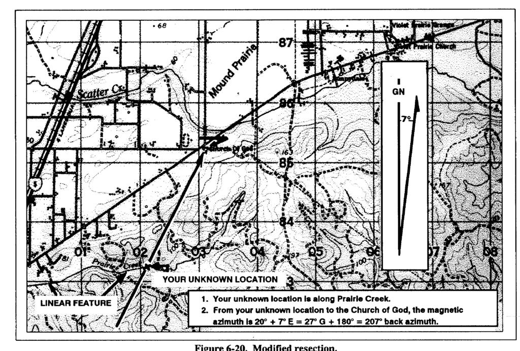
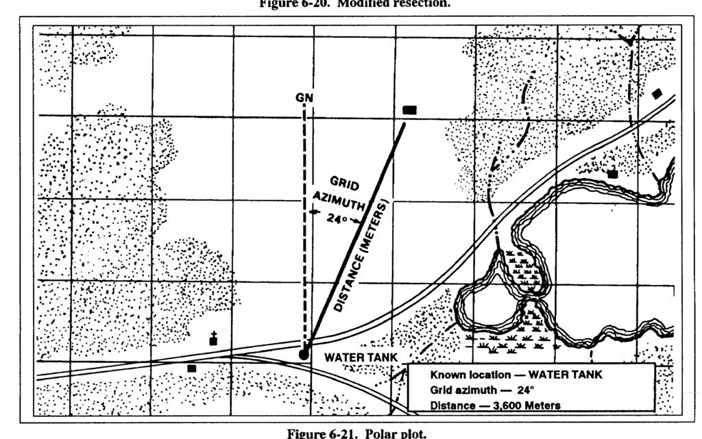
12 (5) Repeat 3 and 4 using a second known position. (6) The intersection of the lines on the map is your location. Determine the grid coordinates to the desired accuracy MODIFIED RESECTION Modified resection is the method of locating one's position on the map when the person is located on a linear feature on the ground, such as a road, canal, or stream (Figure 6-20). Proceed as follows: a. Orient the map using a compass or by terrain association. b. Find a distant point that can be identified on the ground and on the map. c. Determine the magnetic azimuth from your location to the distant known point. d. Convert the magnetic azimuth to a grid azimuth. e. Convert the grid azimuth to a back azimuth. Using a protractor, draw a line for the back azimuth on the map from the known position back toward your unknown position. f. The location of the user is where the line crosses the linear feature. Determine the grid coordinates to the desired accuracy POLAR COORDINATES A method of locating or plotting an unknown position from a known point by giving a direction and a distance along that direction line is called polar coordinates. The following elements must be present when using polar coordinates (Figure 6-21). Present known location on the map. Azimuth (grid or magnetic). Distance (in meters). The use of the laser range finder to determine the range will greatly enhance your accuracy in determining the unknown position's location. 6-12
13 6-13
FM CHAPTER 6 DIRECTION
 CHAPTER 6 DIRECTION Being in the right place at the prescribed time is necessary to successfully accomplish military missions. Direction plays an important role in a soldier's everyday life. It can be
LESSON 6: DETERMINING DIRECTION
 LESSON 6: DETERMINING DIRECTION PURPOSE Directions play an important role in everyday life. People oftentimes express them as right, left, straight ahead, and so forth; but then the question arises, to
Lesson 7 Determining Direction. Key Terms. azimuth back azimuth degree grid azimuth grid north magnetic azimuth magnetic north true north
 Lesson 7 Determining Direction U.S. ARMY Key Terms J R O T C azimuth back azimuth degree grid azimuth grid north magnetic azimuth magnetic north true north WHAT YOU WILL LEARN TO DO Calculate direction
DIRECTION W140003XQ STUDENT HANDOUT
 UNITED STATES MARINE CORPS THE BASIC SCHOOL MARINE CORPS TRAINING COMMAND CAMP BARRETT, VIRGINIA 22134-5019 DIRECTION W140003XQ STUDENT HANDOUT Warrant Officer Basic Course Introduction Importance In This
Reconnaissance and Surveillance Leader s Course Map Reading self study worksheet (Tenino, Washington Map)
") Reconnaissance and Surveillance Leader s Course Map Reading self study worksheet (Tenino, Washington Map) General Knowledge 1. Name the five Basic Colors on a map and what they represent? 1. 2. 3. 4. 5.
Reconnaissance and Surveillance Leader s Course Map Reading self study worksheet (Tenino, Washington Map) General Knowledge 1. Name the five Basic Colors on a map and what they represent? 1. 2. 3. 4. 5.
FIELD-EXPEDIENT SURVEY TECHNIQUES
 APPENDIX C FIELD-EXPEDIENT SURVEY TECHNIQUES Surveyed locations may be provided by the artillery survey personnel. Normally, a map spot location to six-digit or eight-digit grid coordinates is estimated
Lesson 4: Angular measure and azimuths
 PRO TIPS: Map Reading Lesson 4: Angular measure and azimuths References: FM 21-25; FM 21-26; Map Lesson 4 in map section. Study assignment: read FM 21-25 Chapters 7 to 9, then go through this lesson and
TEST EXAM PART 2 INTERMEDIATE LAND NAVIGATION
 NAME DATE TEST EXAM PART 2 INTERMEDIATE LAND NAVIGATION 1. Knowing these four basic skills, it is impossible to be totally lost; what are they? a. Track Present Location / Determine Distance / Sense of
LOCATION W140005XQ STUDENT HANDOUT
 UNITED STATES MARINE CORPS THE BASIC SCHOOL MARINE CORPS TRAINING COMMAND CAMP BARRETT, VIRGINIA 22134-5019 LOCATION W140005XQ STUDENT HANDOUT W14005XQ Introduction Importance In This Lesson The class
PREPARATION OF FIRE CONTROL EQUIPMENT
 CHAPTER 12 PREPARATION OF FIRE CONTROL EQUIPMENT Three types of firing charts can be constructed on the M16/M19 plotting board: the observed firing chart, the modified-observed firing chart, and the surveyed
Referred Deflection. NOTE: Use 2800 and 0700 to avoid any sight blocks caused by the cannon. Figure Preparation of the plotting board.
 Chapter 12 Referred Deflection 12-5. The aiming circle operator gives the referred deflection to the FDC after the section is laid. The referred deflection can be any 100-mil deflection from 0 to 6300,
Distance in mm from nearest latitude line to location x 150 = seconds of latitude Distance in mm between latitude 2.5 tick marks (along the sides)
") LATITUDE FORMULA FOR 1:24000 SCALE WITH 2.5 TICK MARKS Distance in mm from nearest latitude line to location x 150 = seconds of latitude Distance in mm between latitude 2.5 tick marks (along the sides)
LATITUDE FORMULA FOR 1:24000 SCALE WITH 2.5 TICK MARKS Distance in mm from nearest latitude line to location x 150 = seconds of latitude Distance in mm between latitude 2.5 tick marks (along the sides)
Angles and Directions
 Angles and Directions Angles and Directions Definitions Systems of Angle Measurement Angle Arithmetic Horizontal and Vertical Angles Angle and Direction Measuring Equipment 1 Angle Definitions A measure
Angle, symmetry and transformation
 Terms Illustrations Definition Acute angle An angle greater than 0 and less than 90. Alternate angles Where two straight lines are cut by a third, as in the diagrams, the angles d and f (also c and e)
Section 10.1 Polar Coordinates
 Section 10.1 Polar Coordinates Up until now, we have always graphed using the rectangular coordinate system (also called the Cartesian coordinate system). In this section we will learn about another system,
Activity The Coordinate System and Descriptive Geometry
 Activity 1.5.1 The Coordinate System and Descriptive Geometry Introduction North, east, south, and west. Go down the street about six blocks, take a left, and then go north for about 2 miles; you will
Fundamentals of Surveying MSS 220 Prof. Gamal El-Fiky
 Fundamentals of Surveying MSS 220 Prof. Gamal l-fiky Maritime Studies Department, Faculty of Marine Science King Abdulaziz University gamal_elfiky@yahoo.com Room 221 What is Surveying? Surveying is defined
Precalculus 4.1 Notes Angle Measures, Arc Length, and Sector Area
 Precalculus 4.1 Notes Angle Measures, Arc Length, and Sector Area An angle can be formed by rotating one ray away from a fixed ray indicated by an arrow. The fixed ray is the initial side and the rotated
Reflection and Image Formation by Mirrors
 Purpose Theory a. To study the reflection of light Reflection and Image Formation by Mirrors b. To study the formation and characteristics of images formed by different types of mirrors. When light (wave)
Overview for Families
 unit: Graphing Equations Mathematical strand: Algebra The following pages will help you to understand the mathematics that your child is currently studying as well as the type of problems (s)he will solve
A stratum is a pair of surfaces. When defining a stratum, you are prompted to select Surface1 and Surface2.
 That CAD Girl J ennifer dib ona Website: www.thatcadgirl.com Email: thatcadgirl@aol.com Phone: (919) 417-8351 Fax: (919) 573-0351 Volume Calculations Initial Setup You must be attached to the correct Land
Physical Geography Lab Activity #08
 Physical Geography Lab Activity #08 Due date Name Using a compass COR Objective 4 8.1. Introduction The compass is undeniably a valuable tool in finding your way, but it is also useless if you don t know
Surveying Prof. Bharat Lohani Indian Institute of Technology, Kanpur. Lecture - 1 Module - 6 Triangulation and Trilateration
 Surveying Prof. Bharat Lohani Indian Institute of Technology, Kanpur Lecture - 1 Module - 6 Triangulation and Trilateration (Refer Slide Time: 00:21) Welcome to this another lecture on basic surveying.
Objective: Construct perpendicular line segments on a rectangular grid.
 NYS COMMON CORE MATHEMATICS CURRICULUM Lesson 15 5 6 Lesson 15 Objective: Construct perpendicular line segments on a rectangular grid. Suggested Lesson Structure Fluency Practice Concept Development Student
Year 8 Set 2 : Unit 1 : Number 1
 Year 8 Set 2 : Unit 1 : Number 1 Learning Objectives: Level 5 I can order positive and negative numbers I know the meaning of the following words: multiple, factor, LCM, HCF, prime, square, square root,
Module 4. Stereographic projection: concept and application. Lecture 4. Stereographic projection: concept and application
 Module 4 Stereographic projection: concept and application Lecture 4 Stereographic projection: concept and application 1 NPTEL Phase II : IIT Kharagpur : Prof. R. N. Ghosh, Dept of Metallurgical and Materials
ATNS. USING Google EARTH. Version 1
 ATNS USING Google EARTH Version 1 ATNS/HO/Using Google Earth Page 1 25/04/2013 CONTENTS 1. BASIC SETUP 2. NAVIGATING IN GOOGLE EARTH 3. ADDING OBJECTS TO GOOGLE EARTH 4. USER HELP REFERENCES ATNS/HO/Using
Whole Numbers. Integers and Temperature
 Whole Numbers Know the meaning of count and be able to count Know that a whole number is a normal counting number such as 0, 1, 2, 3, 4, Know the meanings of even number and odd number Know that approximating
Vector Addition. Qty Item Part Number 1 Force Table ME-9447B 1 Mass and Hanger Set ME Carpenter s level 1 String
 rev 05/2018 Vector Addition Equipment List Qty Item Part Number 1 Force Table ME-9447B 1 Mass and Hanger Set ME-8979 1 Carpenter s level 1 String Purpose The purpose of this lab is for the student to gain
6th Grade Graphing
 1 6th Grade Graphing 2015-12-02 www.njctl.org 2 Graphing 6th Grade Topics Cartesian Plane Click on the topic to go to that section Graphing Ordered Pairs Polygons in the Coordinate Plane Cartesian Plane
Reteach. Chapter 14. Grade 4
 Reteach Chapter 14 Grade 4 Lesson 1 Reteach Draw Points, Lines, and Rays A point is an exact location that is represented by a dot. Example: point R R A line goes on forever in both directions. Example:
Mathematics Department Inverclyde Academy
 Common Factors I can gather like terms together correctly. I can substitute letters for values and evaluate expressions. I can multiply a bracket by a number. I can use common factor to factorise a sum
Math Geometry FAIM 2015 Form 1-A [ ]
![Math Geometry FAIM 2015 Form 1-A [ ]](/thumbs/80/81205175.jpg "Math Geometry FAIM 2015 Form 1-A [ ]") Math Geometry FAIM 2015 Form 1-A [1530458] Student Class Date Instructions Use your Response Document to answer question 13. 1. Given: Trapezoid EFGH with vertices as shown in the diagram below. Trapezoid
Math Geometry FAIM 2015 Form 1-A [1530458] Student Class Date Instructions Use your Response Document to answer question 13. 1. Given: Trapezoid EFGH with vertices as shown in the diagram below. Trapezoid
Creating and editing vector maps
 Software PHOTOMOD Module PHOTOMOD VectOr Creating and editing vector maps Racurs, Moscow, 2009 PHOTOMOD CONTENTS 1. GENERAL PURPOSE OF VECTOR MAP EDITOR... 3 2. VECTOR MAP EDITOR MANAGING.... 3 3. ADDING
COGO-50 v1.81 User Manual By Jacob Wall
 COGO-50 v1.81 User Manual By Jacob Wall COGO-50 is a (mostly) UserRPL program written for the HP 49g+/50g using ROM Version 2.09 (also tested with ROM Version 2.15). It is a land surveying program capable
LIGHT: Two-slit Interference
 LIGHT: Two-slit Interference Objective: To study interference of light waves and verify the wave nature of light. Apparatus: Two red lasers (wavelength, λ = 633 nm); two orange lasers (λ = 612 nm); two
3.1 Units. Angle Unit. Direction Reference
 Various settings allow the user to configure the software to function to his/her preference. It is important to review all the settings prior to using the software to ensure they are set to produce the
Microscopic Measurement
 Microscopic Measurement Estimating Specimen Size : The area of the slide that you see when you look through a microscope is called the " field of view ". If you know the diameter of your field of view,
Geometry Summer Packet
 Geometry Summer Packet Level 3 Geometry Teachers OVERVIEW This packet is a representation of the type of work and thinking that will be used by High School Geometry students at Columbia High School. The
Tutorial 3: Constructive Editing (2D-CAD)
") (2D-CAD) The editing done up to now is not much different from the normal drawing board techniques. This section deals with commands to copy items we have already drawn, to move them and to make multiple
(2D-CAD) The editing done up to now is not much different from the normal drawing board techniques. This section deals with commands to copy items we have already drawn, to move them and to make multiple
MD5-26 Stacking Blocks Pages
 MD5-26 Stacking Blocks Pages 115 116 STANDARDS 5.MD.C.4 Goals Students will find the number of cubes in a rectangular stack and develop the formula length width height for the number of cubes in a stack.
The Nautical Almanac's Concise Sight Reduction Tables
 The Nautical Almanac's Concise Sight Reduction Tables W. Robert Bernecky February, 2015 This document describes the mathematics used to derive the Nautical Almanac's Concise Sight Reduction Tables (NACSR).
MATHEMATICS 105 Plane Trigonometry
 Chapter I THE TRIGONOMETRIC FUNCTIONS MATHEMATICS 105 Plane Trigonometry INTRODUCTION The word trigonometry literally means triangle measurement. It is concerned with the measurement of the parts, sides,
place value Thousands Hundreds Tens Units
 Number add total altogether sum plus + take away subtract minus the difference multiply times lots of groups of product divide share equally remainder (rem.) digit two digit numbers three digit numbers
ELGIN ACADEMY Mathematics Department Evaluation Booklet (Main) Name Reg
 Name Reg") ELGIN ACADEMY Mathematics Department Evaluation Booklet (Main) Name Reg CfEM You should be able to use this evaluation booklet to help chart your progress in the Maths department from August in S1 until
ELGIN ACADEMY Mathematics Department Evaluation Booklet (Main) Name Reg CfEM You should be able to use this evaluation booklet to help chart your progress in the Maths department from August in S1 until
Optics INTRODUCTION DISCUSSION OF PRINCIPLES. Reflection by a Plane Mirror
 Optics INTRODUCTION Geometric optics is one of the oldest branches of physics, dealing with the laws of reflection and refraction. Reflection takes place on the surface of an object, and refraction occurs
Surveying Prof. Bharat Lohani Department of Civil Engineering Indian Institute of Technology, Kanpur
 Surveying Prof. Bharat Lohani Department of Civil Engineering Indian Institute of Technology, Kanpur Module - 6 Lecture - 2 Triangulation and Trilateration Welcome to this another lecture on basic surveying.
(Refer Slide Time: 00:02:00)
") Computer Graphics Prof. Sukhendu Das Dept. of Computer Science and Engineering Indian Institute of Technology, Madras Lecture - 18 Polyfill - Scan Conversion of a Polygon Today we will discuss the concepts
Computer Graphics Prof. Sukhendu Das Dept. of Computer Science and Engineering Indian Institute of Technology, Madras Lecture - 18 Polyfill - Scan Conversion of a Polygon Today we will discuss the concepts
4.1 Radian and Degree Measure: Day 1. Trignometry is the measurement of triangles.
 4.1 Radian and Degree Measure: Day 1 Trignometry is the measurement of triangles. An angle is formed by rotating a half-line called a ray around its endpoint. The initial side of the angle remains fixed.
Grade 4 ISTEP+ T1 #1-2 ISTEP+ T1 # Identify, describe and draw parallelograms, rhombuses, and ISTEP+ T1 #5-6
 Unit 1 Naming and Constructing Geometric Figures 1 a B Use a compass and straightedge to construct geometric figures. 4.4.1 Identify, describe, and draw rays, right angles, acute angles, obtuse ISTEP+
Lab 21.1 The Tangent Galvanometer
 Name School Date Lab 21.1 The Tangent Galvanometer Purpose To investigate the magnetic field at the center of a current-carrying loop of wire. To verify the right-hand rule for the field inside a current
Papers 1F and 2F (Foundation Tier)
") Papers 1F and 2F (Foundation Tier) Content overview Number Numbers and the number system Algebra Equations, formulae and identities Sequences, functions and graphs Geometry Shape, space and measure Vectors
Papers 1F and 2F (Foundation Tier) Content overview Number Numbers and the number system Algebra Equations, formulae and identities Sequences, functions and graphs Geometry Shape, space and measure Vectors
ES302 Class Notes Trigonometric Applications in Geologic Problem Solving (updated Spring 2016)
") ES302 Class Notes Trigonometric Applications in Geologic Problem Solving (updated Spring 2016) I. Introduction a) Trigonometry study of angles and triangles i) Intersecting Lines (1) Points of intersection
ES302 Class Notes Trigonometric Applications in Geologic Problem Solving (updated Spring 2016) I. Introduction a) Trigonometry study of angles and triangles i) Intersecting Lines (1) Points of intersection
Right Triangles CHAPTER. 3.3 Drafting Equipment Properties of 45º 45º 90º Triangles p. 189
 CHAPTER Right Triangles Hiking is the most popular outdoor activity in the United States, with almost 40% of Americans hiking every year. Hikers should track their location and movements on a map so they
Angles. An angle is: the union of two rays having a common vertex.
 Angles An angle is: the union of two rays having a common vertex. Angles can be measured in both degrees and radians. A circle of 360 in radian measure is equal to 2π radians. If you draw a circle with
Review of 7 th Grade Geometry
 Review of 7 th Grade Geometry In the 7 th Grade Geometry we have covered: 1. Definition of geometry. Definition of a polygon. Definition of a regular polygon. Definition of a quadrilateral. Types of quadrilaterals
( ) Derivation of Polar Reduction Formula for a Calculator Robert Bernecky April, 2018 ( )
 Derivation of Polar Reduction Formula for a Calculator Robert Bernecky April, 2018 ( )") Derivation of Polar Reduction Formula for a Calculator Robert Bernecky April, 2018 1 Problem Statement The polar reduction formula takes an observer's assumed position (lat, lon), and a body's celestial
Derivation of Polar Reduction Formula for a Calculator Robert Bernecky April, 2018 1 Problem Statement The polar reduction formula takes an observer's assumed position (lat, lon), and a body's celestial
Coordinates - Activity 1 Plotting whole number ordered pairs.
 Name: Class: p 3 Maths Helper Plus Resource Set 1. Copyright 2002 Bruce A. Vaughan, Teachers Choice Software Coordinates - Activity 1 Plotting whole number ordered pairs. 1) Start Maths Helper Plus and
Grade 6 Math Circles October 16 & Non-Euclidean Geometry and the Globe
 Faculty of Mathematics Waterloo, Ontario N2L 3G1 Centre for Education in Mathematics and Computing Grade 6 Math Circles October 16 & 17 2018 Non-Euclidean Geometry and the Globe (Euclidean) Geometry Review:
Year 7 Unit 1 - number properties 1
 Year 7 Unit 1 - number properties 1 Order whole numbers using a number line. Place integers and decimals in order of size. Multiply and divide integers and decimals by 10,100, 1000 and explain the effect.
Grade 6 Math Circles October 16 & Non-Euclidean Geometry and the Globe
 Faculty of Mathematics Waterloo, Ontario N2L 3G1 Centre for Education in Mathematics and Computing Grade 6 Math Circles October 16 & 17 2018 Non-Euclidean Geometry and the Globe (Euclidean) Geometry Review:
4 Mathematics Curriculum. Module Overview... i Topic A: Lines and Angles... 4.A.1. Topic B: Angle Measurement... 4.B.1
 New York State Common Core 4 Mathematics Curriculum G R A D E Table of Contents GRADE 4 MODULE 4 Angle Measure and Plane Figures GRADE 4 MODULE 4 Module Overview... i Topic A: Lines and Angles... 4.A.1
Unit 1, Lesson 1: Tiling the Plane
 Unit 1, Lesson 1: Tiling the Plane Let s look at tiling patterns and think about area. 1.1: Which One Doesn t Belong: Tilings Which pattern doesn t belong? 1 1.2: More Red, Green, or Blue? m.openup.org//6-1-1-2
Randy H. Shih. Jack Zecher PUBLICATIONS
 Randy H. Shih Jack Zecher PUBLICATIONS WWW.SDCACAD.COM AutoCAD LT 2000 MultiMedia Tutorial 1-1 Lesson 1 Geometric Construction Basics! " # 1-2 AutoCAD LT 2000 MultiMedia Tutorial Introduction Learning
12.4 Rotations. Learning Objectives. Review Queue. Defining Rotations Rotations
 12.4. Rotations www.ck12.org 12.4 Rotations Learning Objectives Find the image of a figure in a rotation in a coordinate plane. Recognize that a rotation is an isometry. Review Queue 1. Reflect XY Z with
+ b. From this we can derive the following equations:
 A. GEOMETRY REVIEW Pythagorean Theorem (A. p. 58) Hypotenuse c Leg a 9º Leg b The Pythagorean Theorem is a statement about right triangles. A right triangle is one that contains a right angle, that is,
2.1 Motion in Two Dimensions A Scale Diagram Approach
 Figure The motion of these cyclists is two-dimensional in the plane of the road. carr LInK aval offi cers use gyroscopic compasses and satellite navigation to navigate Canada s naval fl eet. However, every
ST MARY S COLLEGE FORM ONE COURSE OUTLINE MATHEMATICS. Term 1. Addition and subtraction. Multiplication and division facts
 ST MARY S COLLEGE FORM ONE COURSE OUTLINE MATHEMATICS Term 1 1 1 Arithmetic: Place Value Definition of number types and the relation to each other Place value for integers. Number in words and vice versa
Chapter 12: Quadratic and Cubic Graphs
 Chapter 12: Quadratic and Cubic Graphs Section 12.1 Quadratic Graphs x 2 + 2 a 2 + 2a - 6 r r 2 x 2 5x + 8 2y 2 + 9y + 2 All the above equations contain a squared number. They are therefore called quadratic
TIPS4Math Grades 4 to 6 Overview Grade 4 Grade 5 Grade 6 Collect, Organize, and Display Primary Data (4+ days)
") Collect, Organize, and Display Primary Data (4+ days) Collect, Organize, Display and Interpret Categorical Data (5+ days) 4m88 Collect data by conducting a survey or an experiment to do with the 4m89 Collect
Collect, Organize, and Display Primary Data (4+ days) Collect, Organize, Display and Interpret Categorical Data (5+ days) 4m88 Collect data by conducting a survey or an experiment to do with the 4m89 Collect
Year 6 Summer Term Week 1 to 2 Geometry: Properties of Shapes
 Measure with a protractor Introduce angles Calculate angles Vertically opposite angles Angles in a triangle Angles in a triangle special cases Angles in a triangle missing angles Angles in special quadrilaterals
Mini-Project 1: The Library of Functions and Piecewise-Defined Functions
 Name Course Days/Start Time Mini-Project 1: The Library of Functions and Piecewise-Defined Functions Part A: The Library of Functions In your previous math class, you learned to graph equations containing
Angles, Straight Lines and Symmetry
 Mathematics GCSE Module Five: Basic Geometry Lesson Fifteen Angles, Straight Lines and Symmetry Aims The aim of this lesson is to enable you to: recognise and apply the basic ideas of Geometry, particularly
Lecture 5. If, as shown in figure, we form a right triangle With P1 and P2 as vertices, then length of the horizontal
 Distance; Circles; Equations of the form Lecture 5 y = ax + bx + c In this lecture we shall derive a formula for the distance between two points in a coordinate plane, and we shall use that formula to
GSN SunShot Procedures Using Internet Solar Position Calculator
 GSN SunShot Procedures Using Internet Solar Position Calculator Purpose: Determine astronomical (true) north for instrument orientation by observing the Sun s azimuth using a Theodolite and Sun Position
Mathematics at Woodcroft Primary School
 Mathematics at Woodcroft Primary School Maths in the Early Years Foundation Stage: In Nursery and Reception they follow the Development Matters and Early Years Learning Goals. Maths is taught in a variety
Complex Numbers, Polar Equations, and Parametric Equations. Copyright 2017, 2013, 2009 Pearson Education, Inc.
 8 Complex Numbers, Polar Equations, and Parametric Equations Copyright 2017, 2013, 2009 Pearson Education, Inc. 1 8.5 Polar Equations and Graphs Polar Coordinate System Graphs of Polar Equations Conversion
Vectors and the Geometry of Space
 Vectors and the Geometry of Space In Figure 11.43, consider the line L through the point P(x 1, y 1, z 1 ) and parallel to the vector. The vector v is a direction vector for the line L, and a, b, and c
Woodcote Primary School Climbing the Ladders of Learning: Maths Milestone 1.1
 Climbing the Ladders of Learning: Maths Milestone 1.1 Number s I can join in with counting beyond 10 I can take away one from a number of objects I can talk about, recognise & copy simple repeating patterns
Section 1.4: Adding and Subtracting Linear and Perpendicular Vectors
 Section 1.4: Adding and Subtracting Linear and Perpendicular Vectors Motion in two dimensions must use vectors and vector diagrams. Vector Representation: tail head magnitude (size): given by the length
Name: Chapter 14 Light. Class: Date: 143 minutes. Time: 143 marks. Marks: Comments: Page 1 of 53
 Chapter 4 Light Name: Class: Date: Time: 43 minutes Marks: 43 marks Comments: Page of 53 A person can see an image of himself in a tall plane mirror. The diagram shows how the person can see his hat. (a)
Working with Plan Production ObjectsChapter1:
 Chapter 1 Working with Plan Production ObjectsChapter1: The lessons in this chapter guide you through the processes of creating and working with plan production objects. Plan production objects include
INSTRUCTIONS FOR THE USE OF THE SUPER RULE TM
 INSTRUCTIONS FOR THE USE OF THE SUPER RULE TM NOTE: All images in this booklet are scale drawings only of template shapes and scales. Preparation: Your SUPER RULE TM is a valuable acquisition for classroom
Summary Of Topics covered in Year 7. Topic All pupils should Most pupils should Some pupils should Learn formal methods for
 Summary Of Topics covered in Year 7 Topic All pupils should Most pupils should Some pupils should Learn formal methods for Have a understanding of computing multiplication Use the order of basic number
10.1 Conversions. Grid to Geodetic
 10.1 Conversions Geodetic conversions work with the current geodetic settings. Convert grid coordinates to geodetic (Latitude/Longitude) or vice versa with any of the available projections. All results
My Target Level 1c. My areas for development:
 My Target Level 1c I can read numbers up to 10 (R) I can count up to 10 objects (R) I can say the number names in order up to 20 (R) I can write at least 4 numbers up to 10. When someone gives me a small
AWM 11 UNIT 4 TRIGONOMETRY OF RIGHT TRIANGLES
 AWM 11 UNIT 4 TRIGONOMETRY OF RIGHT TRIANGLES Assignment Title Work to complete Complete 1 Triangles Labelling Triangles 2 Pythagorean Theorem Exploring Pythagorean Theorem 3 More Pythagorean Theorem Using
Finding the slope to base angle of the virtual pyramid Case 1
 inding the slope to base angle of the virtual pyramid ase 1 igure 1 What we are seeking to find is the measure of angle, or conversely, as triangle is isosceles the two angles at the base will be equal.
Raster Images Processing
 Software PHOTOMOD Module PHOTOMOD VectOr Raster Images Processing Racurs, Moscow, 2009 PHOTOMOD CONTENTS 1. Raster processing in PHOTOMOD VectOr...3 1.1. Raster map...3 1.2. Raster data conversion...4
Georgia Performance Standards for Fourth Grade
 Georgia Performance Standards for Fourth Grade Mathematics Terms for Georgia s (CRCT) Criterion Reference Competency Test Administered in April of Each Year Parents: We are counting on you to help us teach
AW Math 10 UNIT 7 RIGHT ANGLE TRIANGLES
 AW Math 10 UNIT 7 RIGHT ANGLE TRIANGLES Assignment Title Work to complete Complete 1 Triangles Labelling Triangles 2 Pythagorean Theorem 3 More Pythagorean Theorem Eploring Pythagorean Theorem Using Pythagorean
Level 6 PROMPT sheet. 6/3 Divide a quantity into a given ratio. ~ Put headings ~Find how many shares in total ~ Amount no. shares = value of one share
 Level 6 PROMPT sheet 6/ Equivalent fractions, decimals & percentages Percentage to decimal to fraction 7 7% = 0.7 = 00 7 7% = 0.07 = 00 70 7 70% = 0.7 = = 00 0 6/ Divide a quantity into a given ratio ~
This blog addresses the question: how do we determine the intersection of two circles in the Cartesian plane?
 Intersecting Circles This blog addresses the question: how do we determine the intersection of two circles in the Cartesian plane? This is a problem that a programmer might have to solve, for example,
Aston Hall s A-Z of mathematical terms
 Aston Hall s A-Z of mathematical terms The following guide is a glossary of mathematical terms, covering the concepts children are taught in FS2, KS1 and KS2. This may be useful to clear up any homework
Chapter 1. Linear Equations and Straight Lines. 2 of 71. Copyright 2014, 2010, 2007 Pearson Education, Inc.
 Chapter 1 Linear Equations and Straight Lines 2 of 71 Outline 1.1 Coordinate Systems and Graphs 1.4 The Slope of a Straight Line 1.3 The Intersection Point of a Pair of Lines 1.2 Linear Inequalities 1.5
Section 1.3 Adding Integers
 Section 1.3 Adding Integers Objectives In this section, you will learn to: To successfully complete this section, you need to understand: Represent integers as vectors. The integer number line (1.2) Add
Navigational Aids 1 st Semester/2007/TF 7:30 PM -9:00 PM
 Glossary of Navigation Terms accelerometer. A device that senses inertial reaction to measure linear or angular acceleration. In its simplest form, it consists of a case-mounted spring and mass arrangement
In this lesson, you will: Use the Pythagorean Theorem to derive the Distance Formula. Apply the Distance Formula on the coordinate plane.
 A Let s Trip Move! to the Moon Using Translating Tables and to Represent Equivalent Constructing Ratios Line Segments..2 LEARNING GOALS KEY TERMS KEY TERM CONSTRUCTIONS In this lesson, you will: Pythagorean
T.4 Applications of Right Angle Trigonometry
 22 T.4 Applications of Right Angle Trigonometry Solving Right Triangles Geometry of right triangles has many applications in the real world. It is often used by carpenters, surveyors, engineers, navigators,