BRDFs. Steve Rotenberg CSE168: Rendering Algorithms UCSD, Spring 2017
|
|
|
- Barnard Richardson
- 5 years ago
- Views:
Transcription
1 BRDFs Steve Rotenberg CSE168: Rendering Algorithms UCSD, Spring 2017
2 The Rendering Equation
3 Radiance Radiance is a measure of the quantity of light radiation reflected (and/or emitted) from a surface within a given solid angle in a specified direction It is typically measured in units of W/(sr m 2 ) or Watts per steradian meter squared (Note there are 4π steradians in a sphere, just like there are 2π radians in a circle) It is the property we usually associate as light intensity and is what we measure when we are computing the color to display Technically, radiance refers to a single wavelength, and spectral radiance refers to the radiance across a spectrum Spectral radiance is what we associate as the perceived color (including the intensity), and is what we use to determine the pixel color
4 Area of a Hemisphere We can compute the area of a hemisphere by integrating rings ranging over a second angle θ, which ranges from 0 (at the north pole) to π/2 (at the equator) The area of a ring is the circumference of the ring times the width rdθ The circumference is going to be scaled by sinθ as the rings are smaller towards the top of the hemisphere area = 0 π 2 2π sin θ r 2 dφ 0 dθ = 2πr 2
5 Irradiance Now, let s assume that we are interested in computing the total amount of light arriving at some point on a surface We are essentially integrating over all possible directions in a unit hemisphere above the surface (assuming it s opaque and we re not receiving translucent light from below the surface) We are integrating the light intensity (or radiance) coming in from every direction The total incoming radiance over all directions in the hemisphere is called the irradiance We will say that the incoming radiance from any one direction is a function of the direction: L i θ, φ The incoming radiance from each direction is scaled by cosθ to account for the fact that light coming in from a horizontal direction is more spread out than light coming from directly above
6 Irradiance The area of a unit hemisphere is area = 0 π 2 2π sin θ dφ 0 dθ We can compute the irradiance as an integral of the incoming radiance L i over the hemisphere of incoming light directions: irrad = 0 π 2 2π L i θ, φ cos θ sin θ dφ 0 dθ
7 Irradiance irrad = 0 π 2 2π L i θ, φ cos θ sin θ dφ 0 dθ We can simplify the notation a bit. Instead of writing it as a double integral over two angles, we can write it as a single integral over the domain Ω of all possible directions ω irrad = Ω L i ω cos θ dω
8 Irradiance irrad = Ω L i ω cos θ dω ω is a unit vector for some particular direction. To be consistent with convention, these vectors will always point away from the surface regardless of whether they represent incoming of outgoing light Ω is the hemisphere domain, which can be thought of as a (infinite) set of all possible directions in a hemisphere dω is an infinitesimal area element (around direction ω) on the surface of the hemisphere. We don t really care about it s exact shape, just that it represents an infinitesimal portion of the total surface area We know that the surface area of a unit hemisphere is 2π, so by definition: area = Ω dω = 2π
9 BRDFs A bidirectional reflectance distribution function is a four dimensional function that describes how light is reflected off a surface It relates light coming from the incident direction ω i to light reflected in some outward direction ω r f r ω i, ω r Note that because the two vectors are unit length direction vectors, they really only have two independent variables each (the two polar angles describing the direction). Sometimes, BRDFs are written like this: f r θ i, φ i, θ r, φ r
10 Reflected Radiance Let s say that L i ω i is a function that measures the incident radiance from direction ω i When this hits a surface with normal n, this gets scaled by cos θ i to account for the light getting spread out at shallower angles (Note that cos θ i = ω i n) If a beam of light is shining on the surface from one particular direction ω i, then the reflected radiance we see coming off in direction ω r is f r ω i, ω r L i ω i cos θ i
11 Radiance Equation The reflected radiance in direction ω r from a single direction of incoming light ω i is: f r ω i, ω r L i ω i cos θ i We can compute the total reflected radiance L r in direction ω r from the integral of the reflected radiance from every direction of incoming light L r ω r = f r ω i, ω r L i ω i cos θ i dω i Ω This is the radiance equation
12 Rendering Equation The radiance equation calculates the total light reflected off a surface in direction ω r, from all incoming light across the hemisphere L r ω r = f r ω i, ω r L i ω i cos θ i dω i Ω If we include the possibility that the surface is also emitting light, then the total radiance out from the surface in direction ω r is: L out = L emitted + L reflected L ω r = L e ω r + L r ω r This is the rendering equation L ω r = L e ω r + f r ω i, ω r L i ω i cos θ i dω i Ω
13 Rendering Equation L ω r = L e ω r + f r ω i, ω r L i ω i cos θ i dω i Ω When we render an image, we are attempting to evaluate the rendering equation for every pixel in the image We trace a ray from the camera and hit a surface. We then want to calculate the radiance L coming off of that surface going back towards the camera in direction ω r (the opposite of the ray direction)
14 BRDFs
15 BRDF Properties There are two important properties that are required for BRDFs to be physically valid: Conservation of Energy Reciprocity
16 Conservation of Energy Conservation of energy is a fundamental principle in physics It says that energy is never created or destroyed- only changed from one form to another With respect to light scattering from materials, it tells us that the total light reflected off of the material must be less than the light incident on the material ω i, Ω f r ω i, ω r cos θ r d ω r 1
17 Reciprocity Hermann von Helmholtz ( ) was a German physicist who made many contributions to optics, theory of vision, color, thermodynamics, electrodynamics and more In a famous treatise on physiological optics, published in 1856, he formulated the Helmholtz reciprocity principle The principle states that if we follow a beam of light on any path through an optical system, the loss of intensity is the same as for a beam traveling in the reverse direction f r ω i, ω r = f r ω r, ω i
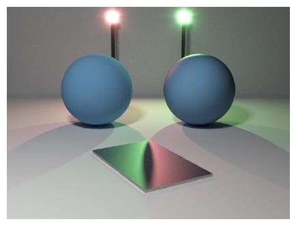
18 Isotropic & Anisotropic A BRDF can be either isotropic or anisotropic An isotropic BRDF doesn t change with respect to surface rotation about the normal Brushed metals and animal fur are good examples of anisotropic materials that do change with respect to orientation For an isotropic BRDF, there is no fixed frame of reference for the φ angles. The absolute angles are irrelevant, but the difference between the two is still important. This effectively reduces the isotropic BRDF to a 3 dimensional function: f r θ i, θ r, φ i φ r
19 Fundamental BRDFs
20 Idealized Surfaces The most fundamental of the physically based BRDFs are the idealized Fresnel specular and Lambert diffuse models Fresnel metal Fresnel dielectric Lambert diffuse
21 Fresnel Metal The Fresnel metal BRDF is 0 everywhere except in the direction of perfect specular reflection, which happens when ω r = reflect(ω i,n)= (ω i n)n-2ω i In that case, the reflectivity is based on the Fresnel equation for metals The reflectivity varies based on the wavelength of the light leading to coloring of the reflection (especially for copper and gold) The coloring can be modeled based on actual optical properties of the metals or can be approximated as just constant colors multiplied times the Fresnel equation
22 Fresnel Dielectric Fresnel dielectrics are clear and split an incident ray into a reflected ray and a refracted ray The Fresnel dielectric is actually a BSDF, since it contains reflecting and transmitting components It is 0 everywhere except where ω r is in the direction of perfect reflection or refraction
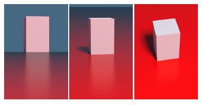
23 Lambert Diffuse The Lambert diffuse BRDF can be written as: f r ω i, ω r = c diff π where c diff is the diffuse color Note that the BRDF itself is constant. The cosine term usually associated with Lambert reflection comes from the cosine term in the radiance equation itself
24 Microfacet Models The Fresnel metal, dielectric, and Lambert BRDFs are all based on the assumption of a perfectly smooth surface These have been extended to roughened surfaces made up of microfacets, where each microfacet is an ideal Fresnel or Lambert reflector The roughened models typically account for shadowing and masking effects between microfacets, as well as interreflections between them
25 Cook-Torrance BRDF The Cook-Torrance (1981) model extends the Fresnel metal model to handle rough metal surfaces The reflectivity is modeled as the product of three terms: Fresnel F(), Geometry G(), and Distribution D() f r ω i, ω r = F ω i h G ω i, ω r D h n 4 ω i n ω r n where h is the halfway vector between ω i and ω r
26 Oren-Nayar BRDF The Oren-Nayar (1994) BRDF takes the ideas from Cook-Torrance and applies them to perfectly diffuse microfacets The resulting model is a more realistic diffuse model that accounts for backscattering due to the opposition effect
27 Oren-Nayar Reflectance Model f r ω i, ω r = ρ π A + B max 0, cos φ i φ r sin α tan β where A = B = 0.45 σ 2 σ σ 2 σ α = max θ i, θ r β = min θ i, θ r σ = roughness (ranges from 0 to around 0.5) φ i φ r =angle between incident and reflected rays projected onto the plane
28 Walter BSDF The BSDF of Walter, Marschner, Li, and Torrance (2007) applies the same concepts to microfacets made of perfect Fresnel dielectrics It is a BSDF (scattering) because it accounts for both reflection and transmission They also explore the use of various different expressions for microfacet distributions D() and geometric attenuation G()
29 Fundamental BRDFs Diffuse Metal Dielectric Ideal (smooth) Lambert Fresnel metal Fresnel dielectric Microfacet (rough) Oren-Nayar Cook-Torrance Walter
30 Empirical BRDFs
31 Empirical Models The fundamental BRDFs that we looked at so far are all based on real physics to varying degrees of approximation There are also several popular BRDFs that are based on empirical formulations that attempt to model the resulting visual phenomena rather than the underlying causes Some examples include: Phong Ward Schlick Ashikhman
32 Phong The Phong model (1971) is a classic empirical model in computer graphics It is still widely in use due to its simplicity and intuitive control When the research focus shifted heavily towards physically based rendering, it was observed that the classic Phong model was not physically valid A modern Phong BRDF was developed that is a minor modification of the original in order to enforce reciprocity and conservation of energy
33 Schlick Christophe Schlick created An Inexpensive BRDF Model for Physically-based Rendering in 1994 It makes some approximations to the Fresnel equation and uses some other fast empirical functions to model diffuse, specular, and a simple layered surface mode It was also designed with sampling in mind and has appropriate functions for generating sample ray directions
34 Ashikhmin In 2000, Michael Ashikhmin and Peter Shirley published a BRDF that remains popular today It is an empirical BRDF intended to model general purpose surfaces from diffuse to plastics to metals They listed 6 main goals for the BRDF: Obey conservation of energy and reciprocity Allow anisotropic reflection Controlled by intuitive parameters Accounts for Fresnel effect Non-constant diffuse term (diffuse decreases as specularity increases) Well suited to Monte Carlo methods
35 Ashikhmin BRDF ρ k 1, k 2 = ρ s k 1, k 2 + ρ d k 1, k 2 ρ s k 1, k 2 = n u + 1 n v + 1 8π n h n ucos 2 φ+n v sin 2 φ h k max n k 1, n k 2 F k h F k h = R s + 1 R s 1 k h 5 ρ d k 1, k 2 = 28R d 23π 1 R s 1 1 n k n k 2 2 5
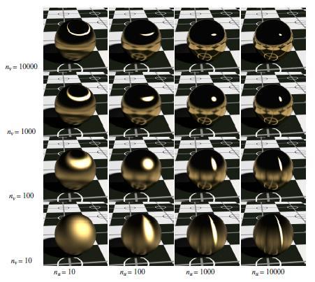
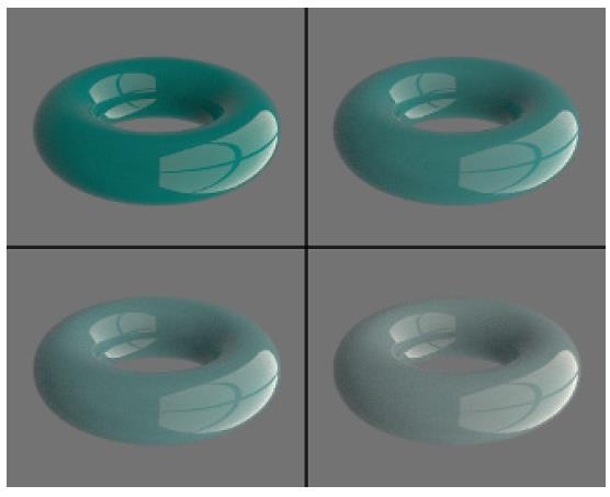
36 Ashikhmin

37 Ashikhmin One of the nicest features of the Ashikhmin BRDF is the effectiveness of the sampling functions

38 Ashikhmin BRDF

39 Direct Light Only
40 Advanced BRDF Concepts
41 Layered Models Many real surfaces are built up of multiple layers of primers, pigments, scattering particles, and clear coatings There have been various attempts to develop BRDFs that account for the interaction of light between these different layers One early model was Reflection from Layered Surfaces due to Subsurface Scattering by Pat Hanrahan and Wolfgang Krueger
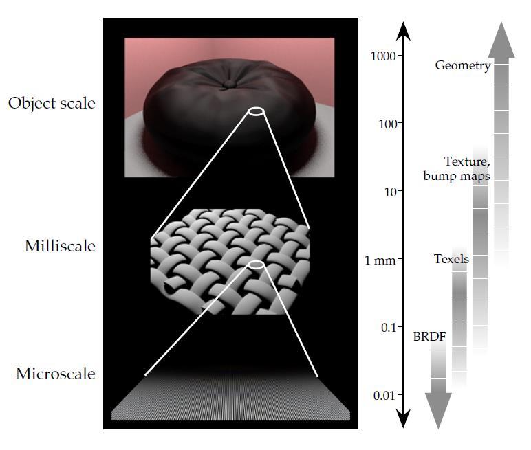
42 Multiscale BRDFs
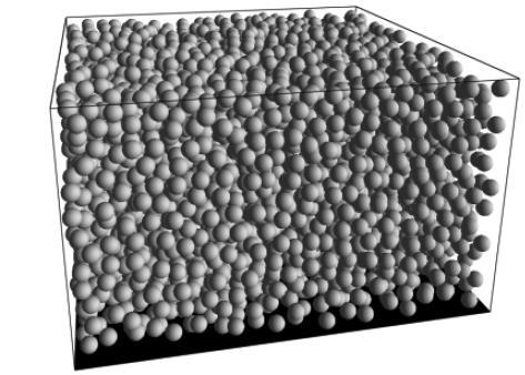
43 Measured BRDFs It is possible to measure a BRDF from a real world material by using a special tool called a gonioreflectometer It takes a sample of the material and illuminates it with a light source and measures the reflection with a light sensor Both the light source and sensor can move to various angles around the sample to measure the BRDF across the whole range of incident and reflected angles
44 Virtual Gonioreflectometer It is also possible to simulate a virtual gonioreflectometer and build BRDF models from actual modeled microgeometry A sample of the surface is modeled with actual geometry Basic material properties are assigned to the microsurfaces such as Fresnel reflection/refraction, particle scattering, absorption, and diffuse reflection Millions of random rays are shot at the material and then bounced around within the material The rays that escape off the surface are measured and contribute to the final BRDF
45 Virtual Gonioreflectometer


46 Westin, Arvo, Torrance A classic paper on multiscale BRDFs and virtual gonioreflectometers is Predicting Reflectance Functions from Complex Surfaces by Stephen Westin, James Arvo, and Kenneth Torrance from 1992

47 Wavelength Dependence Jay Gondek, Gary Meyer, and Jonathan Newman wrote a paper called Wavelength Dependent Reflectance Functions that used a virtual gonioreflectometer to model complex materials They account for wavelength dependent properties such as interference that lead to iridescent effects
48 BRDF Representations Imagine if you were measuring a real material BRDF or simulating one with a virtual setup If you want reasonable resolution, you probably want to sample everything at 1 degree increments or so For an isotropic BRDF, this means sampling two variables over 90 degrees and one over 180 degrees, leading to 90x90x180=1,458,000 data points An anisotropic BRDF would add another dimension of 180, raising it to 262 million data points Various hierarchical, multidimensional data structures have been devised to store and compress BRDF data, and various mathematical tools have been developed to represent and manipulate the data
49 Midterm
50 Midterm The midterm will be in class on Wednesday There will be 10 questions, and it is worth 10% of your grade Topics include everything we ve discussed so far Guidelines: Not very math heavy, but be familiar with core vector & matrix math Pay attention to any terms in italics that are defined in the lecture notes The test will focus more on concepts and understanding In situations where multiple options are discussed (such as BRDF types, data structure types, number sequence types, etc.), be prepared to compare and contrast the different options
51 Camera & Scene Cameras Camera ray generation Look-at function Objects & Scene Objects & ray intersections Instancing logic Spatial data structures
52 Intersections Ray equation: r(t)=p+td Ray-sphere concepts Ray-plane math: d = q n = (p+td) n = p n + td n t = (d-p n) / (d n) Ray-box concepts Ray-triangle concepts Barycentric coordinates: q = a + α(b-a) + β(c-a)
53 Spatial Data Structures Render performance Hierarchical data structures Tree construction Ray traversal BVH vs. spatial partitions AABB, sphere tree, K-Tree, BSP, nested grid, octree Scene graph & animation issues
54 Fresnel Dielectric behavior & concepts Snells law Total internal reflection Metal behavior Concept and trends in Fresnel equation Fresnel effect Beer-Lambert law concepts Recursive ray tracing

55 Materials Diffuse material behavior Microgeometry Shadowing/masking Distribution Opposition effect Oren-Nayar model Cook-Torrance model Isotropic vs. anisotropic
56 Shadows & Area Lights Umbra & penumbra Area light sampling Solid angles
57 Antialiasing Aliasing problems & their causes: shimmering, Moiré, stairstepping, strobing Signals, sampling, & reconstruction concepts Low/high frequency signals Pixel sampling (uniform, jittered, random, weighted )
58 Texture Wrap modes Sampling modes Minification / magnification EWA sampling Normal & displacement mapping concepts
59 Random Sampling Random & jittered numbers Quasi-random numbers Concepts behind mappings
60 BRDFs Bidirectional reflectance distribution function Physical validity: ω Conservation of energy i, f r ω i, ω r cos θ r d Ω Reciprocity f r ω i, ω r = f r ω r, ω i Isotropic vs. anisotropic Qualities of different BRDF models BRDF sampling Radiance equation ω r 1 L r ω r = f r ω i, ω r L i ω i cos θ i dω i Ω
61 Path Tracing Path tracing Monte Carlo integration Rendering equation Local/global illumination
Materials & Shadows. Steve Rotenberg CSE168: Rendering Algorithms UCSD, Winter 2017
 Materials & Shadows Steve Rotenberg CSE168: Rendering Algorithms UCSD, Winter 2017 Diffuse Surfaces In an earlier lecture, we discussed diffuse surfaces We looked at the idealized Lambertian diffuse case
CS 5625 Lec 2: Shading Models
 CS 5625 Lec 2: Shading Models Kavita Bala Spring 2013 Shading Models Chapter 7 Next few weeks Textures Graphics Pipeline Light Emission To compute images What are the light sources? Light Propagation Fog/Clear?
Radiometry & BRDFs CS295, Spring 2017 Shuang Zhao
 Radiometry & BRDFs CS295, Spring 2017 Shuang Zhao Computer Science Department University of California, Irvine CS295, Spring 2017 Shuang Zhao 1 Today s Lecture Radiometry Physics of light BRDFs How materials
Overview. Radiometry and Photometry. Foundations of Computer Graphics (Spring 2012)
") Foundations of Computer Graphics (Spring 2012) CS 184, Lecture 21: Radiometry http://inst.eecs.berkeley.edu/~cs184 Overview Lighting and shading key in computer graphics HW 2 etc. ad-hoc shading models,
Foundations of Computer Graphics (Spring 2012) CS 184, Lecture 21: Radiometry http://inst.eecs.berkeley.edu/~cs184 Overview Lighting and shading key in computer graphics HW 2 etc. ad-hoc shading models,
Reflection models and radiometry Advanced Graphics
 Reflection models and radiometry Advanced Graphics Rafał Mantiuk Computer Laboratory, University of Cambridge Applications To render realistic looking materials Applications also in computer vision, optical
Radiance. Radiance properties. Radiance properties. Computer Graphics (Fall 2008)
") Computer Graphics (Fall 2008) COMS 4160, Lecture 19: Illumination and Shading 2 http://www.cs.columbia.edu/~cs4160 Radiance Power per unit projected area perpendicular to the ray per unit solid angle in
Computer Graphics (Fall 2008) COMS 4160, Lecture 19: Illumination and Shading 2 http://www.cs.columbia.edu/~cs4160 Radiance Power per unit projected area perpendicular to the ray per unit solid angle in
Path Tracing part 2. Steve Rotenberg CSE168: Rendering Algorithms UCSD, Spring 2017
 Path Tracing part 2 Steve Rotenberg CSE168: Rendering Algorithms UCSD, Spring 2017 Monte Carlo Integration Monte Carlo Integration The rendering (& radiance) equation is an infinitely recursive integral
The Rendering Equation. Computer Graphics CMU /15-662
 The Rendering Equation Computer Graphics CMU 15-462/15-662 Review: What is radiance? Radiance at point p in direction N is radiant energy ( #hits ) per unit time, per solid angle, per unit area perpendicular
BRDF Computer Graphics (Spring 2008)
") BRDF Computer Graphics (Spring 2008) COMS 4160, Lecture 20: Illumination and Shading 2 http://www.cs.columbia.edu/~cs4160 Reflected Radiance proportional to Irradiance Constant proportionality: BRDF [CW
BRDF Computer Graphics (Spring 2008) COMS 4160, Lecture 20: Illumination and Shading 2 http://www.cs.columbia.edu/~cs4160 Reflected Radiance proportional to Irradiance Constant proportionality: BRDF [CW
Illumination and Shading - II
 Illumination and Shading - II Computer Graphics COMP 770 (236) Spring 2007 Instructor: Brandon Lloyd 2/19/07 1 From last time Light Sources Empirical Illumination Shading Local vs Global Illumination 2/19/07
Lecture 4: Reflection Models
 Lecture 4: Reflection Models CS 660, Spring 009 Kavita Bala Computer Science Cornell University Outline Light sources Light source characteristics Types of sources Light reflection Physics-based models
CENG 477 Introduction to Computer Graphics. Ray Tracing: Shading
 CENG 477 Introduction to Computer Graphics Ray Tracing: Shading Last Week Until now we learned: How to create the primary rays from the given camera and image plane parameters How to intersect these rays
CMSC427 Shading Intro. Credit: slides from Dr. Zwicker
 CMSC427 Shading Intro Credit: slides from Dr. Zwicker 2 Today Shading Introduction Radiometry & BRDFs Local shading models Light sources Shading strategies Shading Compute interaction of light with surfaces
Lights, Surfaces, and Cameras. Light sources emit photons Surfaces reflect & absorb photons Cameras measure photons
 Reflectance 1 Lights, Surfaces, and Cameras Light sources emit photons Surfaces reflect & absorb photons Cameras measure photons 2 Light at Surfaces Many effects when light strikes a surface -- could be:
Radiometry and reflectance
 Radiometry and reflectance http://graphics.cs.cmu.edu/courses/15-463 15-463, 15-663, 15-862 Computational Photography Fall 2018, Lecture 16 Course announcements Homework 4 is still ongoing - Any questions?
dq dt I = Irradiance or Light Intensity is Flux Φ per area A (W/m 2 ) Φ =
 Φ =") Radiometry (From Intro to Optics, Pedrotti -4) Radiometry is measurement of Emag radiation (light) Consider a small spherical source Total energy radiating from the body over some time is Q total Radiant
Radiometry (From Intro to Optics, Pedrotti -4) Radiometry is measurement of Emag radiation (light) Consider a small spherical source Total energy radiating from the body over some time is Q total Radiant
INFOGR Computer Graphics. J. Bikker - April-July Lecture 10: Shading Models. Welcome!
 INFOGR Computer Graphics J. Bikker - April-July 2016 - Lecture 10: Shading Models Welcome! Today s Agenda: Introduction Light Transport Materials Sensors Shading INFOGR Lecture 10 Shading Models 3 Introduction
Global Illumination. CSCI 420 Computer Graphics Lecture 18. BRDFs Raytracing and Radiosity Subsurface Scattering Photon Mapping [Ch
 CSCI 420 Computer Graphics Lecture 18 Global Illumination Jernej Barbic University of Southern California BRDFs Raytracing and Radiosity Subsurface Scattering Photon Mapping [Ch. 13.4-13.5] 1 Global Illumination
And if that 120MP Camera was cool
 Reflectance, Lights and on to photometric stereo CSE 252A Lecture 7 And if that 120MP Camera was cool Large Synoptic Survey Telescope 3.2Gigapixel camera 189 CCD s, each with 16 megapixels Pixels are 10µm
CS6670: Computer Vision
 CS6670: Computer Vision Noah Snavely Lecture 20: Light, reflectance and photometric stereo Light by Ted Adelson Readings Szeliski, 2.2, 2.3.2 Light by Ted Adelson Readings Szeliski, 2.2, 2.3.2 Properties
Global Illumination. CMPT 361 Introduction to Computer Graphics Torsten Möller. Machiraju/Zhang/Möller
 Global Illumination CMPT 361 Introduction to Computer Graphics Torsten Möller Reading Foley, van Dam (better): Chapter 16.7-13 Angel: Chapter 5.11, 11.1-11.5 2 Limitation of local illumination A concrete
Local Reflection Models
 Local Reflection Models Illumination Thus Far Simple Illumination Models Ambient + Diffuse + Attenuation + Specular Additions Texture, Shadows, Used in global algs! (Ray tracing) Problem: Different materials
Visual Appearance and Color. Gianpaolo Palma
 Visual Appearance and Color Gianpaolo Palma LIGHT MATERIAL Visual Appearance Color due to the interaction between the lighting environment (intensity, position, ) and the properties of the object surface
CS6670: Computer Vision
 CS6670: Computer Vision Noah Snavely Lecture 21: Light, reflectance and photometric stereo Announcements Final projects Midterm reports due November 24 (next Tuesday) by 11:59pm (upload to CMS) State the
Image Formation: Light and Shading. Introduction to Computer Vision CSE 152 Lecture 3
 Image Formation: Light and Shading CSE 152 Lecture 3 Announcements Homework 1 is due Apr 11, 11:59 PM Homework 2 will be assigned on Apr 11 Reading: Chapter 2: Light and Shading Geometric image formation
Global Illumination. Global Illumination. Direct Illumination vs. Global Illumination. Indirect Illumination. Soft Shadows.
 CSCI 480 Computer Graphics Lecture 18 Global Illumination BRDFs Raytracing and Radiosity Subsurface Scattering Photon Mapping [Ch. 13.4-13.5] March 28, 2012 Jernej Barbic University of Southern California
Specular reflection. Lighting II. Snell s Law. Refraction at boundary of media
 Specular reflection Lighting II CS 465 Lecture 19 Smooth surfaces of pure materials have ideal specular reflection (said this before) Metals (conductors) and dielectrics (insulators) behave differently
Rendering Light Reflection Models
 Rendering Light Reflection Models Visual Imaging in the Electronic Age Donald P. Greenberg October 3, 2017 Lecture #13 Program of Computer Graphics, Cornell University General Electric - 167 Cornell in
Shading. Brian Curless CSE 557 Autumn 2017
 Shading Brian Curless CSE 557 Autumn 2017 1 Reading Optional: Angel and Shreiner: chapter 5. Marschner and Shirley: chapter 10, chapter 17. Further reading: OpenGL red book, chapter 5. 2 Basic 3D graphics
The Rendering Equation. Computer Graphics CMU /15-662, Fall 2016
 The Rendering Equation Computer Graphics CMU 15-462/15-662, Fall 2016 Review: What is radiance? Radiance at point p in direction N is radiant energy ( #hits ) per unit time, per solid angle, per unit area
Global Illumination. Global Illumination. Direct Illumination vs. Global Illumination. Indirect Illumination. Soft Shadows.
 CSCI 420 Computer Graphics Lecture 18 Global Illumination Jernej Barbic University of Southern California BRDFs Raytracing and Radiosity Subsurface Scattering Photon Mapping [Angel Ch. 11] 1 Global Illumination
Lecture 7 - Path Tracing
 INFOMAGR Advanced Graphics Jacco Bikker - November 2016 - February 2017 Lecture 7 - I x, x = g(x, x ) ε x, x + S ρ x, x, x I x, x dx Welcome! Today s Agenda: Introduction Advanced Graphics 3 Introduction
782 Schedule & Notes
 782 Schedule & Notes Tentative schedule - subject to change at a moment s notice. This is only a guide and not meant to be a strict schedule of how fast the material will be taught. The order of material
Global Illumination The Game of Light Transport. Jian Huang
 Global Illumination The Game of Light Transport Jian Huang Looking Back Ray-tracing and radiosity both computes global illumination Is there a more general methodology? It s a game of light transport.
Visual cues to 3D geometry. Light Reflection and Advanced Shading. Shading. Recognizing materials. size (perspective) occlusion shading
 occlusion shading") Visual cues to 3D geometry Light Reflection and Advanced Shading size (perspective) occlusion shading CS 4620 Lecture 17 1 2 Shading Recognizing materials Variation in observed color across an object strongly
Visual cues to 3D geometry Light Reflection and Advanced Shading size (perspective) occlusion shading CS 4620 Lecture 17 1 2 Shading Recognizing materials Variation in observed color across an object strongly
Lecture 22: Basic Image Formation CAP 5415
 Lecture 22: Basic Image Formation CAP 5415 Today We've talked about the geometry of scenes and how that affects the image We haven't talked about light yet Today, we will talk about image formation and
Lighting affects appearance
 Lighting affects appearance 1 Source emits photons Light And then some reach the eye/camera. Photons travel in a straight line When they hit an object they: bounce off in a new direction or are absorbed
Shading & Material Appearance
 Shading & Material Appearance ACM. All rights reserved. This content is excluded from our Creative Commons license. For more information, see http://ocw.mit.edu/help/faq-fair-use/. MIT EECS 6.837 Matusik
Introduction. Lighting model Light reflection model Local illumination model Reflectance model BRDF
 Shading Introduction Affine transformations help us to place objects into a scene. Before creating images of these objects, we ll look at models for how light interacts with their surfaces. Such a model
Fundamentals of Rendering - Reflectance Functions
 Fundamentals of Rendering - Reflectance Functions Image Synthesis Torsten Möller Mike Phillips Reading Chapter 8 of Physically Based Rendering by Pharr&Humphreys Chapter 16 in Foley, van Dam et al. Chapter
Computer Graphics (CS 543) Lecture 8 (Part 1): Physically-Based Lighting Models
 Lecture 8 (Part 1): Physically-Based Lighting Models") Computer Graphics (CS 543) Lecture 8 (Part 1): Physically-Based Lighting Models Prof Emmanuel Agu Computer Science Dept. Worcester Polytechnic Institute (WPI) BRDF Evolution BRDFs have evolved historically
Computer Graphics (CS 543) Lecture 8 (Part 1): Physically-Based Lighting Models Prof Emmanuel Agu Computer Science Dept. Worcester Polytechnic Institute (WPI) BRDF Evolution BRDFs have evolved historically
Capturing light. Source: A. Efros
 Capturing light Source: A. Efros Review Pinhole projection models What are vanishing points and vanishing lines? What is orthographic projection? How can we approximate orthographic projection? Lenses
dq dt I = Irradiance or Light Intensity is Flux Φ per area A (W/m 2 ) Φ =
 Φ =") Radiometry (From Intro to Optics, Pedrotti -4) Radiometry is measurement of Emag radiation (light) Consider a small spherical source Total energy radiating from the body over some time is Q total Radiant
Radiometry (From Intro to Optics, Pedrotti -4) Radiometry is measurement of Emag radiation (light) Consider a small spherical source Total energy radiating from the body over some time is Q total Radiant
Rendering: Reality. Eye acts as pinhole camera. Photons from light hit objects
 Basic Ray Tracing Rendering: Reality Eye acts as pinhole camera Photons from light hit objects Rendering: Reality Eye acts as pinhole camera Photons from light hit objects Rendering: Reality Eye acts as
02 Shading and Frames. Steve Marschner CS5625 Spring 2016
 02 Shading and Frames Steve Marschner CS5625 Spring 2016 Light reflection physics Radiometry redux Power Intensity power per unit solid angle Irradiance power per unit area Radiance power per unit (solid
Radiometry. Reflectance & Lighting. Solid Angle. Radiance. Radiance Power is energy per unit time
 Radiometry Reflectance & Lighting Computer Vision I CSE5A Lecture 6 Read Chapter 4 of Ponce & Forsyth Homework 1 Assigned Outline Solid Angle Irradiance Radiance BRDF Lambertian/Phong BRDF By analogy with
The Light Field. Last lecture: Radiometry and photometry
 The Light Field Last lecture: Radiometry and photometry This lecture: Light field = radiance function on rays Conservation of radiance Measurement equation Throughput and counting rays Irradiance calculations
w Foley, Section16.1 Reading
 Shading w Foley, Section16.1 Reading Introduction So far, we ve talked exclusively about geometry. w What is the shape of an object? w How do I place it in a virtual 3D space? w How do I know which pixels
Computer Graphics. Illumination and Shading
 () Illumination and Shading Dr. Ayman Eldeib Lighting So given a 3-D triangle and a 3-D viewpoint, we can set the right pixels But what color should those pixels be? If we re attempting to create a realistic
rendering equation computer graphics rendering equation 2009 fabio pellacini 1
 rendering equation computer graphics rendering equation 2009 fabio pellacini 1 physically-based rendering synthesis algorithms that compute images by simulation the physical behavior of light computer
Announcement. Lighting and Photometric Stereo. Computer Vision I. Surface Reflectance Models. Lambertian (Diffuse) Surface.
 Surface.") Lighting and Photometric Stereo CSE252A Lecture 7 Announcement Read Chapter 2 of Forsyth & Ponce Might find section 12.1.3 of Forsyth & Ponce useful. HW Problem Emitted radiance in direction f r for incident
Lighting and Photometric Stereo CSE252A Lecture 7 Announcement Read Chapter 2 of Forsyth & Ponce Might find section 12.1.3 of Forsyth & Ponce useful. HW Problem Emitted radiance in direction f r for incident
Today. Global illumination. Shading. Interactive applications. Rendering pipeline. Computergrafik. Shading Introduction Local shading models
 Computergrafik Matthias Zwicker Universität Bern Herbst 2009 Today Introduction Local shading models Light sources strategies Compute interaction of light with surfaces Requires simulation of physics Global
Radiometry. Radiometry. Measuring Angle. Solid Angle. Radiance
 Radiometry Radiometry Computer Vision I CSE5A ecture 5-Part II Read Chapter 4 of Ponce & Forsyth Solid Angle Irradiance Radiance BRDF ambertian/phong BRDF Measuring Angle Solid Angle By analogy with angle
Comp 410/510 Computer Graphics. Spring Shading
 Comp 410/510 Computer Graphics Spring 2017 Shading Why we need shading Suppose we build a model of a sphere using many polygons and then color it using a fixed color. We get something like But we rather
2/1/10. Outline. The Radiance Equation. Light: Flux Equilibrium. Light: Radiant Power. Light: Equation. Radiance. Jan Kautz
 Outline Jan Kautz Basic terms in radiometry Radiance Reflectance The operator form of the radiance equation Meaning of the operator form Approximations to the radiance equation 2005 Mel Slater, 2006 Céline
Rendering Light Reflection Models
 Rendering Light Reflection Models Visual Imaging in the Electronic Age Donald P. Greenberg October 27, 2015 Lecture #18 Goal of Realistic Imaging The resulting images should be physically accurate and
Announcements. Light. Properties of light. Light. Project status reports on Wednesday. Readings. Today. Readings Szeliski, 2.2, 2.3.
 Announcements Project status reports on Wednesday prepare 5 minute ppt presentation should contain: problem statement (1 slide) description of approach (1 slide) some images (1 slide) current status +
Light Reflection Models
 Light Reflection Models Visual Imaging in the Electronic Age Donald P. Greenberg October 21, 2014 Lecture #15 Goal of Realistic Imaging From Strobel, Photographic Materials and Processes Focal Press, 186.
Photometric Stereo.
 Photometric Stereo Photometric Stereo v.s.. Structure from Shading [1] Photometric stereo is a technique in computer vision for estimating the surface normals of objects by observing that object under
Fundamentals of Rendering - Reflectance Functions
 Fundamentals of Rendering - Reflectance Functions CMPT 461/761 Image Synthesis Torsten Möller Reading Chapter 8 of Physically Based Rendering by Pharr&Humphreys Chapter 16 in Foley, van Dam et al. Chapter
Announcements. Image Formation: Light and Shading. Photometric image formation. Geometric image formation
 Announcements Image Formation: Light and Shading Homework 0 is due Oct 5, 11:59 PM Homework 1 will be assigned on Oct 5 Reading: Chapters 2: Light and Shading CSE 252A Lecture 3 Geometric image formation
Shading. Reading. Pinhole camera. Basic 3D graphics. Brian Curless CSE 557 Fall Required: Shirley, Chapter 10
 Reading Required: Shirley, Chapter 10 Shading Brian Curless CSE 557 Fall 2014 1 2 Basic 3D graphics With affine matrices, we can now transform virtual 3D objects in their local coordinate systems into
Announcements. Radiometry and Sources, Shadows, and Shading
 Announcements Radiometry and Sources, Shadows, and Shading CSE 252A Lecture 6 Instructor office hours This week only: Thursday, 3:45 PM-4:45 PM Tuesdays 6:30 PM-7:30 PM Library (for now) Homework 1 is
Recollection. Models Pixels. Model transformation Viewport transformation Clipping Rasterization Texturing + Lights & shadows
 Recollection Models Pixels Model transformation Viewport transformation Clipping Rasterization Texturing + Lights & shadows Can be computed in different stages 1 So far we came to Geometry model 3 Surface
Ray Tracing: shading
 Ray Tracing: shading CS 4620 Lecture 6 2018 Steve Marschner 1 Image so far With eye ray generation and scene intersection for 0
Complex Shading Algorithms
 Complex Shading Algorithms CPSC 414 Overview So far Rendering Pipeline including recent developments Today Shading algorithms based on the Rendering Pipeline Arbitrary reflection models (BRDFs) Bump mapping
Lecture 15: Shading-I. CITS3003 Graphics & Animation
 Lecture 15: Shading-I CITS3003 Graphics & Animation E. Angel and D. Shreiner: Interactive Computer Graphics 6E Addison-Wesley 2012 Objectives Learn that with appropriate shading so objects appear as threedimensional
CSE 681 Illumination and Phong Shading
 CSE 681 Illumination and Phong Shading Physics tells us What is Light? We don t see objects, we see light reflected off of objects Light is a particle and a wave The frequency of light What is Color? Our
Experimental Validation of Analytical BRDF Models
 Experimental Validation of Analytical BRDF Models Addy Ngan, Frédo Durand, Wojciech Matusik Massachusetts Institute of Technology Goal Evaluate and analyze the performance of analytical reflectance models
Local Illumination. CMPT 361 Introduction to Computer Graphics Torsten Möller. Machiraju/Zhang/Möller
 Local Illumination CMPT 361 Introduction to Computer Graphics Torsten Möller Graphics Pipeline Hardware Modelling Transform Visibility Illumination + Shading Perception, Interaction Color Texture/ Realism
Ray Tracing: Special Topics CSCI 4239/5239 Advanced Computer Graphics Spring 2018
 Ray Tracing: Special Topics CSCI 4239/5239 Advanced Computer Graphics Spring 2018 Theoretical foundations Ray Tracing from the Ground Up Chapters 13-15 Bidirectional Reflectance Distribution Function BRDF
CS580: Ray Tracing. Sung-Eui Yoon ( 윤성의 ) Course URL:
 Course URL:") CS580: Ray Tracing Sung-Eui Yoon ( 윤성의 ) Course URL: http://sglab.kaist.ac.kr/~sungeui/gcg/ Recursive Ray Casting Gained popularity in when Turner Whitted (1980) recognized that recursive ray casting could
CS580: Ray Tracing Sung-Eui Yoon ( 윤성의 ) Course URL: http://sglab.kaist.ac.kr/~sungeui/gcg/ Recursive Ray Casting Gained popularity in when Turner Whitted (1980) recognized that recursive ray casting could
rendering equation computer graphics rendering equation 2009 fabio pellacini 1
 rendering equation computer graphics rendering equation 2009 fabio pellacini 1 phsicall-based rendering snthesis algorithms that compute images b simulation the phsical behavior of light computer graphics
Lighting and Reflectance COS 426
 ighting and Reflectance COS 426 Ray Casting R2mage *RayCast(R3Scene *scene, int width, int height) { R2mage *image = new R2mage(width, height); for (int i = 0; i < width; i++) { for (int j = 0; j < height;
Ligh%ng and Reflectance
 Ligh%ng and Reflectance 2 3 4 Ligh%ng Ligh%ng can have a big effect on how an object looks. Modeling the effect of ligh%ng can be used for: Recogni%on par%cularly face recogni%on Shape reconstruc%on Mo%on
I have a meeting with Peter Lee and Bob Cosgrove on Wednesday to discuss the future of the cluster. Computer Graphics
 Announcements Assignment 4 will be out later today Problem Set 3 is due today or tomorrow by 9am in my mail box (4 th floor NSH) How are the machines working out? I have a meeting with Peter Lee and Bob
Physically-Based Reflectance for Games
 Physically-Based Reflectance for Games 8:40-9:15: Reflectance Naty Hoffman 15 Reflectance Types of Reflectance Reflectance Theory Reflection Model Foundations In this section, we will first discuss various
CSE 167: Introduction to Computer Graphics Lecture #6: Lights. Jürgen P. Schulze, Ph.D. University of California, San Diego Fall Quarter 2016
 CSE 167: Introduction to Computer Graphics Lecture #6: Lights Jürgen P. Schulze, Ph.D. University of California, San Diego Fall Quarter 2016 Announcements Thursday in class: midterm #1 Closed book Material
Timothy Walsh. Reflection Models
 Timothy Walsh Reflection Models Outline Reflection Models Geometric Setting Fresnel Reflectance Specular Refletance & Transmission Microfacet Models Lafortune Model Fresnel Incidence Effects Diffuse Scatter
Biased Monte Carlo Ray Tracing
 Biased Monte Carlo Ray Tracing Filtering, Irradiance Caching, and Photon Mapping Henrik Wann Jensen Stanford University May 23, 2002 Unbiased and Consistent Unbiased estimator: E{X} =... Consistent estimator:
A question from Piazza
 Radiometry, Reflectance, Lights CSE 252A Lecture 6 A question from Piazza 1 Announcements HW1 posted HWO graded, will be returned today If anyone has any registration issues, talk to me. Appearance: lighting,
CS130 : Computer Graphics Lecture 8: Lighting and Shading. Tamar Shinar Computer Science & Engineering UC Riverside
 CS130 : Computer Graphics Lecture 8: Lighting and Shading Tamar Shinar Computer Science & Engineering UC Riverside Why we need shading Suppose we build a model of a sphere using many polygons and color
Global Illumination and the Rendering Equation
 CS294-13: Special Topics Lecture #3 Advanced Computer Graphics University of California, Berkeley Handout Date??? Global Illumination and the Rendering Equation Lecture #3: Wednesday, 9 September 2009
Shading I Computer Graphics I, Fall 2008
 Shading I 1 Objectives Learn to shade objects ==> images appear threedimensional Introduce types of light-material interactions Build simple reflection model Phong model Can be used with real time graphics
Simple Lighting/Illumination Models
 Simple Lighting/Illumination Models Scene rendered using direct lighting only Photograph Scene rendered using a physically-based global illumination model with manual tuning of colors (Frederic Drago and
6. Illumination, Lighting
 Jorg s Graphics Lecture Notes 6. Illumination, Lighting 1 6. Illumination, Lighting No ray tracing in OpenGL! ray tracing: direct paths COP interreflection: soft shadows, color bleeding. umbra, penumbra,
Philpot & Philipson: Remote Sensing Fundamentals Interactions 3.1 W.D. Philpot, Cornell University, Fall 12
 Philpot & Philipson: Remote Sensing Fundamentals Interactions 3.1 W.D. Philpot, Cornell University, Fall 1 3. EM INTERACTIONS WITH MATERIALS In order for an object to be sensed, the object must reflect,
Monte Carlo Ray Tracing. Computer Graphics CMU /15-662
 Monte Carlo Ray Tracing Computer Graphics CMU 15-462/15-662 TODAY: Monte Carlo Ray Tracing How do we render a photorealistic image? Put together many of the ideas we ve studied: - color - materials - radiometry
Local vs. Global Illumination & Radiosity
 Last Time? Local vs. Global Illumination & Radiosity Ray Casting & Ray-Object Intersection Recursive Ray Tracing Distributed Ray Tracing An early application of radiative heat transfer in stables. Reading
Ray Tracing. Brian Curless CSEP 557 Fall 2016
 Ray Tracing Brian Curless CSEP 557 Fall 2016 1 Reading Required: Shirley, section 10.1-10.7 (online handout) Triangle intersection (online handout) Further reading: Shirley errata on syllabus page, needed
Understanding Variability
 Understanding Variability Why so different? Light and Optics Pinhole camera model Perspective projection Thin lens model Fundamental equation Distortion: spherical & chromatic aberration, radial distortion
Illumination and Shading
 Illumination and Shading Computer Graphics COMP 770 (236) Spring 2007 Instructor: Brandon Lloyd 2/14/07 1 From last time Texture mapping overview notation wrapping Perspective-correct interpolation Texture
CS354 Computer Graphics Ray Tracing. Qixing Huang Januray 24th 2017
 CS354 Computer Graphics Ray Tracing Qixing Huang Januray 24th 2017 Graphics Pipeline Elements of rendering Object Light Material Camera Geometric optics Modern theories of light treat it as both a wave
Reflectance & Lighting
 Reflectance & Lighting Computer Vision I CSE5A Lecture 6 Last lecture in a nutshell Need for lenses (blur from pinhole) Thin lens equation Distortion and aberrations Vignetting CS5A, Winter 007 Computer
Global Illumination CS334. Daniel G. Aliaga Department of Computer Science Purdue University
 Global Illumination CS334 Daniel G. Aliaga Department of Computer Science Purdue University Recall: Lighting and Shading Light sources Point light Models an omnidirectional light source (e.g., a bulb)
The Halfway Vector Disk for BRDF Modeling
 The Halfway Vector Disk for BRDF Modeling DAVE EDWARDS, SOLOMON BOULOS, JARED JOHNSON and PETER SHIRLEY University of Utah MICHAEL ASHIKHMIN State University of New York, Stony Brook MICHAEL STARK University
Shading, lighting, & BRDF Theory. Cliff Lindsay, PHD
 Shading, lighting, & BRDF Theory Cliff Lindsay, PHD Overview of today s lecture BRDF Characteristics Lights in terms of BRDFs Classes of BRDFs Ambient light & Shadows in terms of BRDFs Decomposing Reflection
Sung-Eui Yoon ( 윤성의 )
") CS380: Computer Graphics Ray Tracing Sung-Eui Yoon ( 윤성의 ) Course URL: http://sglab.kaist.ac.kr/~sungeui/cg/ Class Objectives Understand overall algorithm of recursive ray tracing Ray generations Intersection
CS380: Computer Graphics Ray Tracing Sung-Eui Yoon ( 윤성의 ) Course URL: http://sglab.kaist.ac.kr/~sungeui/cg/ Class Objectives Understand overall algorithm of recursive ray tracing Ray generations Intersection
Reflectance Models (BRDF)
") Reflectance Models (BRDF) 1996-2017 Josef Pelikán CGG MFF UK Praha pepca@cgg.mff.cuni.cz http://cgg.mff.cuni.cz/~pepca/ BRDF 2017 Josef Pelikán, http://cgg.mff.cuni.cz/~pepca 1 / 62 Light travels through
Reflectance Models (BRDF) 1996-2017 Josef Pelikán CGG MFF UK Praha pepca@cgg.mff.cuni.cz http://cgg.mff.cuni.cz/~pepca/ BRDF 2017 Josef Pelikán, http://cgg.mff.cuni.cz/~pepca 1 / 62 Light travels through
INFOGR Computer Graphics. J. Bikker - April-July Lecture 10: Ground Truth. Welcome!
 INFOGR Computer Graphics J. Bikker - April-July 2015 - Lecture 10: Ground Truth Welcome! Today s Agenda: Limitations of Whitted-style Ray Tracing Monte Carlo Path Tracing INFOGR Lecture 10 Ground Truth