THE EFFECTS OF THE PLANFORM SHAPE ON DRAG POLAR CURVES OF WINGS: FLUID-STRUCTURE INTERACTION ANALYSES RESULTS
|
|
|
- Sarah Marjorie Parks
- 5 years ago
- Views:
Transcription


1 March 18-20, 2013 THE EFFECTS OF THE PLANFORM SHAPE ON DRAG POLAR CURVES OF WINGS: FLUID-STRUCTURE INTERACTION ANALYSES RESULTS Authors: M.R. Chiarelli, M. Ciabattari, M. Cagnoni, G. Lombardi Speaker: Aerospace Engineer Matteo CIABATTARI
2 Relationship between Critical Conditions and the component U cosλ

3 The reaction moments and stress values at the root of the curved wing are reduced by about 5% - 8 % Abstract AEROELASTIC ANALYSES OF TWO HALF WING MODELS: CURVED AND SWEPT PLAN - FORM The curved plan-form causes a variable angle of sweep along the wing span, so, in the transonic flight conditions wave drag effects are strongly reduced The effects of the plan-form shape on drag polar curves (fixed values of CL) leads to the reduction of CD of 7% - 10% The curved plan-form configuration improves the wing s aeroelastic behavior : Analyses have been carried out by using STAR - CCM and Abaqus 6.11 in co - simulation


4 Index 1. Introduction 2. Rigid wing s model : STAR - CCM CFD analyses 3. Elastic wing s model : Fluid - structure - interaction (FSI) analyses STAR - CCM and Abaqus 6.11 co - simulation 4. Detailed analysis of rigid and elastic models results 5. Conclusions and future research activity
 = 0.")

5 1.Introduction: Wings characteristic geometry Half wing area (S) = 239 m 2 Aspect ratio (AR) = 7.53 Taper ratio (λ) = Dihedral angle = 0 Leading edge equation y = x x Supercritical airfoil lies on planes parallel to the longitudinal plane of the wing half models Supercritical airfoil NASA SC(02) 0410 Not twisted airfoils along the half span

6 Volume of the aerodynamic field built in Catia V5 R20 300,000 hexahedral cells around the wing 100,000 free cells in the far field 2. Rigid wing s model : STAR - CCM CFD analyses

 Equation of State Ideal")
7 2. Rigid wing s model : STAR - CCM CFD analyses Settings of the CFD model in STAR-CCM Properties standard air H = 10,000 m Density ρ = kg/m 3 Static temperature T = k Static pressure p = 26,500 Pa Kinematic viscosity ν = m/s 2 Physic model set into STAR-CCM Space Three Dimensional Motion Stationary Time Steady Material Gas Flow Coupled (Momentum and Energy) Equation of State Ideal Gas (Compressible) Viscous Regime Turbulent Reynolds-Averaged Turbulent k-ε Model
8 CFD analysis results between the two rigid wing models (CL= 0.4) 200 hours of CPU simulation ( 2 dual core personal computer with 8 GB RAM each one)
9 CFD analysis results between the two rigid wing models (CL= 0.4) MACH CD RIGID CURVED WING CD RIGID SWEPT WING ΔCD %

 Structural model of swept and curved wing has been built by using Catia V5 R20 Structural properties and dimensions have been assigned to the components (SKIN, STRINGERS, RIBS, SPARS) in Abaqus 6.")
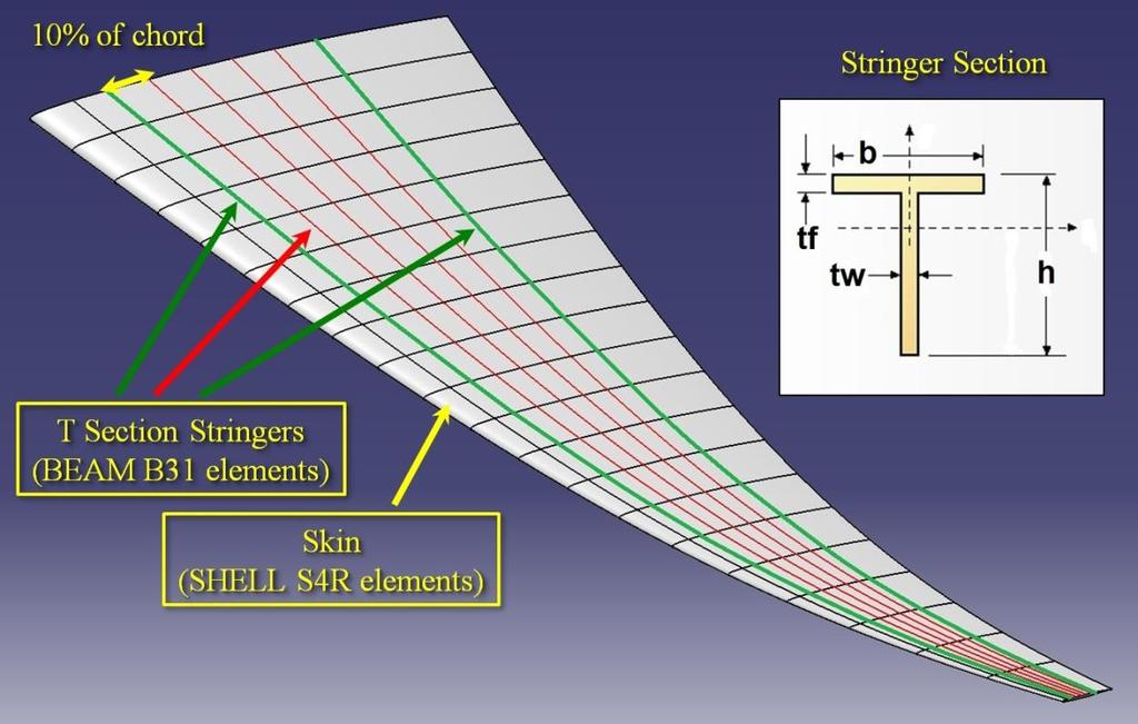
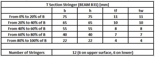
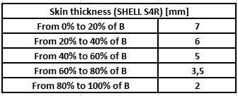
10 3. Co-simulation : STAR-CCM and Abaqus 6.11 The CFD model and the FEM structural model must be perfectly complementary in the areas where take place the exchange of the nodal forces and the displacement nodal values: in Catia V5 R20 an aerodynamic field that surround the wing is constructed (slide n. 6) Structural model of swept and curved wing has been built by using Catia V5 R20 Structural properties and dimensions have been assigned to the components (SKIN, STRINGERS, RIBS, SPARS) in Abaqus 6.11 Both models have the same dimensions for all their characteristic components The results (static Aeroelastic analyses) do not take into account the distributions of the structural or not structural weight: little influence on the deformation shape of the wing at the examined flight conditions

11 3. Co-simulation : STAR-CCM and Abaqus 6.11
12 3. Co-simulation : STAR-CCM and Abaqus 6.11
13 3. Co-simulation : STAR-CCM and Abaqus 6.11 MATERIAL PROPERTIES (AL 7075) DENSITY [kg/m 3 ] 2,700 YOUNG MODULUS [MPa] 71,000 POISSON MODULUS 0.3 MASS OF THE HALF WING STRUCTURE [kg] CURVED WING 10,203 SWEPT WING 10,125 NUMBER OF STRUCTURE MESH ELEMENTS CURVED WING 1,456 SWEPT WING 1,525
14 Set in the CFD code STAR-CCM an implicit unsteady analysis 500 hours of CPU co - simulation to obtain these results
15 Set in the CFD code STAR-CCM an implicit unsteady analysis 500 hours of CPU co simulation to obtain these results
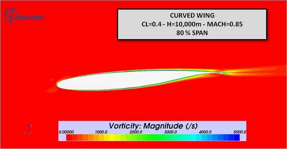
16 FLIGHT CONDITIONS : H = 10,000 m ; MACH = 0.85 ; CL = 0.4 ELASTIC CURVED WING CD PRESSURE CD SHEAR CD TOT NOSE UPPER SURFACE LOWER SURFACE Tot ELASTIC SWEPT WING CD PRESSURE CD SHEAR CD TOT NOSE UPPER SURFACE LOWER SURFACE Tot ΔCD PRESSURE % ΔCD SHEAR % ΔCD TOT % NOSE UPPER LOWER Tot
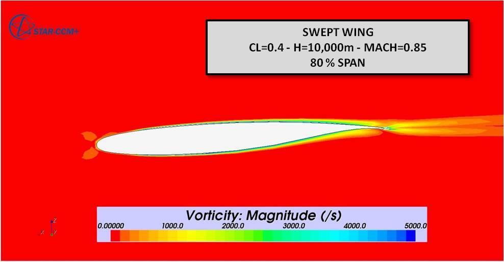
17 The intensity of the shock wave on the curved wing is lower than the intensity of the shock wave on the swept wing Retardation of the boundary layer separation and an increase of aerodynamic efficiency (E = L/D) of the wing
18

19 A comparison of the in plant shape and position of the wave front on the two wings upper surface

20 A comparison of the in plant shape and position of the wave front on the two wings upper surface
21 FLIGHT CONDITIONS : H = 10,000 m ; MACH = 0.85 ; CL = 0.4 Front view: supersonic zone on the upper surface of the two wings The sonic boundary, the red surface which enclose the supersonic region around the wing, has a different shape and different dimensions comparing the swept wing with the curved wing, especially toward the tip of the two wings


22 FLIGHT CONDITIONS : H = 10,000 m ; MACH = 0.85 ; CL = 0.4 Rear view: supersonic zone on the upper surface of the two wings The sonic boundary, the red surface which enclose the supersonic region around the wing, has a different shape and different dimensions comparing the swept wing with the curved wing, especially toward the tip of the two wings
23
24
25
26 4. Detailed analysis of rigid and elastic model results The Elasticity effects lower values of CL for fixed value of angle of attack
27 4. Detailed analysis of rigid and elastic model results The Elasticity effects lower values of CD for fixed value of angle of attack
 is not influenced by the deformation effects, due to the reduction of the aerodynamic loads along the span of the two")
28 4. Detailed analysis of rigid and elastic model results The drag polar curves CL - CD are quite similar for the two model elastic and rigid wing The CD 0 value (drag coefficient corresponding to zero value of the lift) is not influenced by the deformation effects, due to the reduction of the aerodynamic loads along the span of the two wings
29 4. Detailed analysis of rigid and elastic model results The estimated distribution of the aerodynamic load along the half span for the two elastic wings: the resultant lift for the curved wing tends to move inwards and this causes the reduction of moment characteristics at the root of the wing box.


30 4. Detailed analysis of rigid and elastic model results The results by the structural FE models of wings: at the clamped section for the curved wing model the stresses are less of 5 % than the swept wing model. It depends on the reduction of both the bending and torque moment at the root of the wing.

31 5. Conclusion Also taking into account the elasticity effect of the wing - box structure the curved plan-form of a wing favorable influences both CP and MACH distribution along the wing span The results discussed in the present paper agree with previous results published by the authors and confirm that the feasibility of the examined novel wing configuration can be reach adopting standard design technology Flight conditions: H = m ; CL =0.4 ; MACH = 0.85 The curved wing shows a reduction of CD of 7% than the swept wing The structural bending moment and torsion moment of curved elastic model are less of 5% : the stresses in the skin of the curved wing are less of 5%


32 5. Conclusion The pressure rise across the shock wave is less intense and smoother in the curved wing. The adverse pressure gradient towards the trailing edge is reduced. The separation of the boundary layer of the curved wing is delayed with respect to the swept wing in transonic regime, with consequent beneficial effects on the drag ( the aerodynamic efficiency tends to increase)

33 5. Conclusion The plant shape of the shock wave front is strongly influenced by the shape of the wings

, the effects of the curved plan-form configuration of a wing is not negligible from the aerodynamic point of view in the transonic")
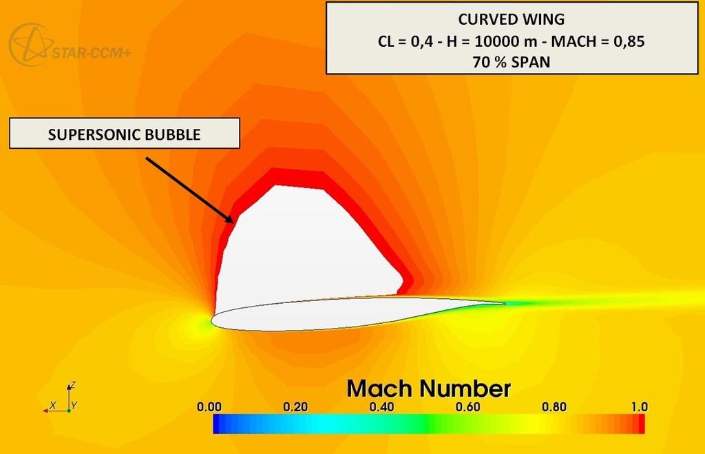
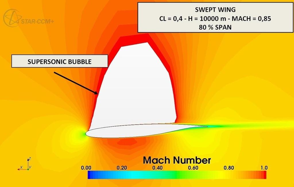
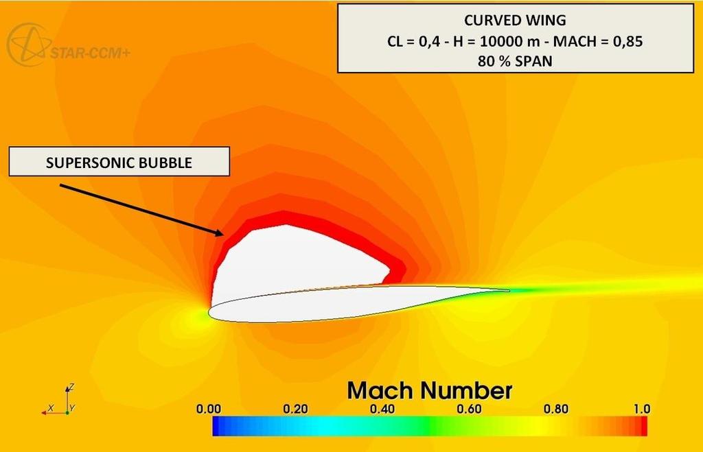
34 5. Conclusion The shape and dimensions of the supersonic zone around the wing (the bubble zone) are strongly influenced by the shape of the wing: the perturbation of the curved wing is less intense and then the energy dissipated in the transonic phenomena around it reduces at same values of CL and MACH of flight Within the limits of a comparative study the result obtained confirm that, also adopting a fluid - structure interaction procedure (FSI), the effects of the curved plan-form configuration of a wing is not negligible from the aerodynamic point of view in the transonic regime.
35 Thanks to the Co-simulation by using STAR-CCM and Abaqus 6.11 It has been possible to examine with a good level of reliability a complex Aeroelastic phenomena with minimum computational resources : Only two Personal Computer with 8 GB of Ram each one Future research activity Dynamic response analyses ( Flutter Behavior) by using FSI analysis procedure : Co - simulation by using STAR-CCM and Abaqus 6.11


36 THE END (For the moment...) Thank you Prof. Eng. Mario Rosario CHIARELLI ( - University of Pisa, Italy) phone number: chiarelli@dia.unipi.it Speaker: Aerospace Eng. Matteo CIABATTARI phone number : matteo.ciabattari@hotmail.com or matteo.ciabattari@gmail.com
Introduction to CFX. Workshop 2. Transonic Flow Over a NACA 0012 Airfoil. WS2-1. ANSYS, Inc. Proprietary 2009 ANSYS, Inc. All rights reserved.
 Workshop 2 Transonic Flow Over a NACA 0012 Airfoil. Introduction to CFX WS2-1 Goals The purpose of this tutorial is to introduce the user to modelling flow in high speed external aerodynamic applications.
Introduction to ANSYS CFX
 Workshop 03 Fluid flow around the NACA0012 Airfoil 16.0 Release Introduction to ANSYS CFX 2015 ANSYS, Inc. March 13, 2015 1 Release 16.0 Workshop Description: The flow simulated is an external aerodynamics
NUMERICAL 3D TRANSONIC FLOW SIMULATION OVER A WING
 Review of the Air Force Academy No.3 (35)/2017 NUMERICAL 3D TRANSONIC FLOW SIMULATION OVER A WING Cvetelina VELKOVA Department of Technical Mechanics, Naval Academy Nikola Vaptsarov,Varna, Bulgaria (cvetelina.velkova1985@gmail.com)
An efficient method for predicting zero-lift or boundary-layer drag including aeroelastic effects for the design environment
 The Aeronautical Journal November 2015 Volume 119 No 1221 1451 An efficient method for predicting zero-lift or boundary-layer drag including aeroelastic effects for the design environment J. A. Camberos
Modeling External Compressible Flow
 Tutorial 3. Modeling External Compressible Flow Introduction The purpose of this tutorial is to compute the turbulent flow past a transonic airfoil at a nonzero angle of attack. You will use the Spalart-Allmaras
Coupled Analysis of FSI
 Coupled Analysis of FSI Qin Yin Fan Oct. 11, 2008 Important Key Words Fluid Structure Interface = FSI Computational Fluid Dynamics = CFD Pressure Displacement Analysis = PDA Thermal Stress Analysis = TSA
39th AIAA Aerospace Sciences Meeting and Exhibit January 8 11, 2001/Reno, NV
 AIAA 1 717 Static Aero-elastic Computation with a Coupled CFD and CSD Method J. Cai, F. Liu Department of Mechanical and Aerospace Engineering University of California, Irvine, CA 92697-3975 H.M. Tsai,
CFD Analysis of conceptual Aircraft body
 CFD Analysis of conceptual Aircraft body Manikantissar 1, Dr.Ankur geete 2 1 M. Tech scholar in Mechanical Engineering, SD Bansal college of technology, Indore, M.P, India 2 Associate professor in Mechanical
Fluid-Structure Interaction Over an Aircraft Wing
 International Journal of Engineering Research and Development e-issn: 2278-067X, p-issn: 2278-800X, www.ijerd.com Volume 13, Issue 4 (April 2017), PP.27-31 Fluid-Structure Interaction Over an Aircraft
Fluid-Structure Interaction in STAR-CCM+ Alan Mueller CD-adapco
 Fluid-Structure Interaction in STAR-CCM+ Alan Mueller CD-adapco What is FSI? Air Interaction with a Flexible Structure What is FSI? Water/Air Interaction with a Structure Courtesy CFD Marine Courtesy Germanischer
Debojyoti Ghosh. Adviser: Dr. James Baeder Alfred Gessow Rotorcraft Center Department of Aerospace Engineering
 Debojyoti Ghosh Adviser: Dr. James Baeder Alfred Gessow Rotorcraft Center Department of Aerospace Engineering To study the Dynamic Stalling of rotor blade cross-sections Unsteady Aerodynamics: Time varying
Application of Wray-Agarwal Turbulence Model for Accurate Numerical Simulation of Flow Past a Three-Dimensional Wing-body
 Washington University in St. Louis Washington University Open Scholarship Mechanical Engineering and Materials Science Independent Study Mechanical Engineering & Materials Science 4-28-2016 Application
Aerodynamic Analysis of Forward Swept Wing Using Prandtl-D Wing Concept
 Aerodynamic Analysis of Forward Swept Wing Using Prandtl-D Wing Concept Srinath R 1, Sahana D S 2 1 Assistant Professor, Mangalore Institute of Technology and Engineering, Moodabidri-574225, India 2 Assistant
Express Introductory Training in ANSYS Fluent Workshop 04 Fluid Flow Around the NACA0012 Airfoil
 Express Introductory Training in ANSYS Fluent Workshop 04 Fluid Flow Around the NACA0012 Airfoil Dimitrios Sofialidis Technical Manager, SimTec Ltd. Mechanical Engineer, PhD PRACE Autumn School 2013 -
ANALYSIS OF AIRCRAFT WING WITH DIFFERENT MATERIALS USING ANSYS SOFTWARE
 ANALYSIS OF AIRCRAFT WING WITH DIFFERENT MATERIALS USING ANSYS SOFTWARE K.Ravindra 1, P.V Divakar Raju 2 1 PG Scholar,Mechanical Engineering,Chadalawada Ramanamma Engineering College,Tirupati,Andhra Pradesh,India.
Second Symposium on Hybrid RANS-LES Methods, 17/18 June 2007
 1 Zonal-Detached Eddy Simulation of Transonic Buffet on a Civil Aircraft Type Configuration V.BRUNET and S.DECK Applied Aerodynamics Department The Buffet Phenomenon Aircraft in transonic conditions Self-sustained
Numerical Simulations of Fluid-Structure Interaction Problems using MpCCI
 Numerical Simulations of Fluid-Structure Interaction Problems using MpCCI François Thirifay and Philippe Geuzaine CENAERO, Avenue Jean Mermoz 30, B-6041 Gosselies, Belgium Abstract. This paper reports
MSC Software Aeroelastic Tools. Mike Coleman and Fausto Gill di Vincenzo
 MSC Software Aeroelastic Tools Mike Coleman and Fausto Gill di Vincenzo MSC Software Confidential 2 MSC Software Confidential 3 MSC Software Confidential 4 MSC Software Confidential 5 MSC Flightloads An
State of the art at DLR in solving aerodynamic shape optimization problems using the discrete viscous adjoint method
 DLR - German Aerospace Center State of the art at DLR in solving aerodynamic shape optimization problems using the discrete viscous adjoint method J. Brezillon, C. Ilic, M. Abu-Zurayk, F. Ma, M. Widhalm
CFD++ APPLICATION ON WIND TUNNEL DATA ANALYSIS
 CFD++ APPLICATION ON WIND TUNNEL DATA ANALYSIS Introduction Piaggio Aero Industries is actually studing a new mid size jet for civilian use. Many people and many disciplines are implicated but up to now
AERODYNAMIC DESIGN FOR WING-BODY BLENDED AND INLET
 25 TH INTERNATIONAL CONGRESS OF THE AERONAUTICAL SCIENCES AERODYNAMIC DESIGN FOR WING-BODY BLENDED AND INLET Qingzhen YANG*,Yong ZHENG* & Thomas Streit** *Northwestern Polytechincal University, 772,Xi
Keisuke Sawada. Department of Aerospace Engineering Tohoku University
 March 29th, 213 : Next Generation Aircraft Workshop at Washington University Numerical Study of Wing Deformation Effect in Wind-Tunnel Testing Keisuke Sawada Department of Aerospace Engineering Tohoku
Constrained Aero-elastic Multi-Point Optimization Using the Coupled Adjoint Approach
 www.dlr.de Chart 1 Aero-elastic Multi-point Optimization, M.Abu-Zurayk, MUSAF II, 20.09.2013 Constrained Aero-elastic Multi-Point Optimization Using the Coupled Adjoint Approach M. Abu-Zurayk MUSAF II
Grid. Apr 09, 1998 FLUENT 5.0 (2d, segregated, lam) Grid. Jul 31, 1998 FLUENT 5.0 (2d, segregated, lam)
 Grid. Jul 31, 1998 FLUENT 5.0 (2d, segregated, lam)") Tutorial 2. Around an Airfoil Transonic Turbulent Flow Introduction: The purpose of this tutorial is to compute the turbulent flow past a transonic airfoil at a non-zero angle of attack. You will use the
Tutorial 2. Around an Airfoil Transonic Turbulent Flow Introduction: The purpose of this tutorial is to compute the turbulent flow past a transonic airfoil at a non-zero angle of attack. You will use the
Optimization of Laminar Wings for Pro-Green Aircrafts
 Optimization of Laminar Wings for Pro-Green Aircrafts André Rafael Ferreira Matos Abstract This work falls within the scope of aerodynamic design of pro-green aircraft, where the use of wings with higher
Usage of CFX for Aeronautical Simulations
 Usage of CFX for Aeronautical Simulations Florian Menter Development Manager Scientific Coordination ANSYS Germany GmbH Overview Elements of CFD Technology for aeronautical simulations: Grid generation
An advanced RBF Morph application: coupled CFD-CSM Aeroelastic Analysis of a Full Aircraft Model and Comparison to Experimental Data
 An advanced RBF Morph application: coupled CFD-CSM Aeroelastic Analysis of a Full Aircraft Model and Comparison to Experimental Data Ubaldo Cella 1 Piaggio Aero Industries, Naples, Italy Marco Evangelos
Estimation of Flow Field & Drag for Aerofoil Wing
 Estimation of Flow Field & Drag for Aerofoil Wing Mahantesh. HM 1, Prof. Anand. SN 2 P.G. Student, Dept. of Mechanical Engineering, East Point College of Engineering, Bangalore, Karnataka, India 1 Associate
NUMERICAL AND EXPERIMENTAL INVESTIGATIONS OF TEST MODELS AERODYNAMICS
 NUMERICAL AND EXPERIMENTAL INVESTIGATIONS OF TEST MODELS AERODYNAMICS A.V. Vaganov, S.M. Drozdov, S.M. Zadonsky, V.I. Plyashechnic, M.A. Starodubtsev, S.V. Chernov, V.L. Yumashev TsAGI, 140180 Zhukovsky,
OPTIMIZATIONS OF AIRFOIL AND WING USING GENETIC ALGORITHM
 ICAS22 CONGRESS OPTIMIZATIONS OF AIRFOIL AND WING USING GENETIC ALGORITHM F. Zhang, S. Chen and M. Khalid Institute for Aerospace Research (IAR) National Research Council (NRC) Ottawa, K1A R6, Ontario,
Adjoint Solver Workshop
 Adjoint Solver Workshop Why is an Adjoint Solver useful? Design and manufacture for better performance: e.g. airfoil, combustor, rotor blade, ducts, body shape, etc. by optimising a certain characteristic
UNSTEADY RANS BASED IMPULSE RESPONSE STUDIES OF AGARD WING FOR AEROELASTIC AND FLUTTER ANALYSIS
 Symposium on Applied Aerodynamics and Design of Aerospace Vehicles (SAROD 2) November 68, 2, Bangalore, India UNSTEADY RANS BASED IMPULSE RESPONSE STUDIES OF AGARD WING FOR AEROELASTIC AND FLUTTER ANALYSIS
The Spalart Allmaras turbulence model
 The Spalart Allmaras turbulence model The main equation The Spallart Allmaras turbulence model is a one equation model designed especially for aerospace applications; it solves a modelled transport equation
Modeling Unsteady Compressible Flow
 Tutorial 4. Modeling Unsteady Compressible Flow Introduction In this tutorial, FLUENT s density-based implicit solver is used to predict the timedependent flow through a two-dimensional nozzle. As an initial
Offshore Platform Fluid Structure Interaction (FSI) Simulation
 Simulation") Offshore Platform Fluid Structure Interaction (FSI) Simulation Ali Marzaban, CD-adapco Murthy Lakshmiraju, CD-adapco Nigel Richardson, CD-adapco Mike Henneke, CD-adapco Guangyu Wu, Chevron Pedro M. Vargas,
Offshore Platform Fluid Structure Interaction (FSI) Simulation Ali Marzaban, CD-adapco Murthy Lakshmiraju, CD-adapco Nigel Richardson, CD-adapco Mike Henneke, CD-adapco Guangyu Wu, Chevron Pedro M. Vargas,
Shock Wave Reduction via Wing-Strut Geometry Design
 Shock Wave Reduction via Wing-Strut Geometry Design Runze LI, Wei NIU, Haixin CHEN School of Aerospace Engineering Beijing 84, China PADRI, Barcelona (Spain) 27..29 SHORT VERSION Shock Wave Reduction via
(c)2002 American Institute of Aeronautics & Astronautics or Published with Permission of Author(s) and/or Author(s)' Sponsoring Organization.
2002 American Institute of Aeronautics & Astronautics or Published with Permission of Author(s) and/or Author(s)' Sponsoring Organization.") VIIA Adaptive Aerodynamic Optimization of Regional Introduction The starting point of any detailed aircraft design is (c)2002 American Institute For example, some variations of the wing planform may become
VIIA Adaptive Aerodynamic Optimization of Regional Introduction The starting point of any detailed aircraft design is (c)2002 American Institute For example, some variations of the wing planform may become
Analysis Comparison between CFD and FEA of an Idealized Concept V- Hull Floor Configuration in Two Dimensions
 2010 NDIA GROUND VEHICLE SYSTEMS ENGINEERING AND TECHNOLOGY SYMPOSIUM MODELING & SIMULATION, TESTING AND VALIDATION (MSTV) MINI-SYMPOSIUM AUGUST 17-19 DEARBORN, MICHIGAN Analysis Comparison between CFD
UNSTEADY TAU AND ROM FOR FLUTTER COMPUTATIONS OF TRANSPORT AIRCRAFT. Reik Thormann, Ralph Voß. Folie 1
 UNSTEADY TAU AND ROM FOR FLUTTER COMPUTATIONS OF TRANSPORT AIRCRAFT Reik Thormann, Ralph Voß Folie 1 Standardfoliensatz >01.03.2007 Outline Motivation Synthetic Mode Correction (SMC) Linearized CFD Method
High-Lift Aerodynamics: STAR-CCM+ Applied to AIAA HiLiftWS1 D. Snyder
 High-Lift Aerodynamics: STAR-CCM+ Applied to AIAA HiLiftWS1 D. Snyder Aerospace Application Areas Aerodynamics Subsonic through Hypersonic Aeroacoustics Store release & weapons bay analysis High lift devices
The Use of Computational Fluid Dynamics In the Aerospace Industry Past Present - Future
 The Use of Computational Fluid Dynamics In the Aerospace Industry Past Present - Future Douglas N. Ball Aerospace Consultant 1 The Early Days Not much CFD in these old birds! Great airplanes none the less.
MSC/NASTRAN FLUTTER ANALYSES OF T-TAILS INCLUDING HORIZONTAL STABILIZER STATIC LIFT EFFECTS AND T-TAIL TRANSONIC DIP
 MSC/NASTRAN FLUTTER ANALYSES OF T-TAILS INCLUDING HORIZONTAL STABILIZER STATIC LIFT EFFECTS AND T-TAIL TRANSONIC DIP by Emil Suciu* Gulfstream Aerospace Corporation Savannah, Georgia U.S.A. Presented at
Numerical Investigation of Transonic Shock Oscillations on Stationary Aerofoils
 Numerical Investigation of Transonic Shock Oscillations on Stationary Aerofoils A. Soda, T. Knopp, K. Weinman German Aerospace Center DLR, Göttingen/Germany Symposium on Hybrid RANS-LES Methods Stockholm/Sweden,
AIR LOAD CALCULATION FOR ISTANBUL TECHNICAL UNIVERSITY (ITU), LIGHT COMMERCIAL HELICOPTER (LCH) DESIGN ABSTRACT
, LIGHT COMMERCIAL HELICOPTER (LCH) DESIGN ABSTRACT") AIR LOAD CALCULATION FOR ISTANBUL TECHNICAL UNIVERSITY (ITU), LIGHT COMMERCIAL HELICOPTER (LCH) DESIGN Adeel Khalid *, Daniel P. Schrage + School of Aerospace Engineering, Georgia Institute of Technology
AIR LOAD CALCULATION FOR ISTANBUL TECHNICAL UNIVERSITY (ITU), LIGHT COMMERCIAL HELICOPTER (LCH) DESIGN Adeel Khalid *, Daniel P. Schrage + School of Aerospace Engineering, Georgia Institute of Technology
SPC 307 Aerodynamics. Lecture 1. February 10, 2018
 SPC 307 Aerodynamics Lecture 1 February 10, 2018 Sep. 18, 2016 1 Course Materials drahmednagib.com 2 COURSE OUTLINE Introduction to Aerodynamics Review on the Fundamentals of Fluid Mechanics Euler and
University of Texas VSP Structural Analysis Module Update - Demonstration
 University of Texas VSP Structural Analysis Module Update - Demonstration http://vspsam.ae.utexas.edu/ VSP Workshop, San Luis Obispo, CA Hersh Amin Armand J. Chaput Department of Aerospace Engineering
Development of an Integrated Computational Simulation Method for Fluid Driven Structure Movement and Acoustics
 Development of an Integrated Computational Simulation Method for Fluid Driven Structure Movement and Acoustics I. Pantle Fachgebiet Strömungsmaschinen Karlsruher Institut für Technologie KIT Motivation
How to Enter and Analyze a Wing
 How to Enter and Analyze a Wing Entering the Wing The Stallion 3-D built-in geometry creation tool can be used to model wings and bodies of revolution. In this example, a simple rectangular wing is modeled
Computational shock and Mach waves visualization aiding the development of aerodynamic design techniques
 Computational shock and Mach waves visualization aiding the development of aerodynamic design techniques H. Sobieczky, M. Hannemann Inst. of Fluid Mechanics, DLR German Aerospace Research Establishment,
TAU mesh deformation. Thomas Gerhold
 TAU mesh deformation Thomas Gerhold The parallel mesh deformation of the DLR TAU-Code Introduction Mesh deformation method & Parallelization Results & Applications Conclusion & Outlook Introduction CFD
FEM analysis of joinwing aircraft configuration
 FEM analysis of joinwing aircraft configuration Jacek Mieloszyk PhD, Miłosz Kalinowski st. Nowowiejska 24, 00-665, Warsaw, Mazowian District, Poland jmieloszyk@meil.pw.edu.pl ABSTRACT Novel aircraft configuration
ANSYS FLUENT. Airfoil Analysis and Tutorial
 ANSYS FLUENT Airfoil Analysis and Tutorial ENGR083: Fluid Mechanics II Terry Yu 5/11/2017 Abstract The NACA 0012 airfoil was one of the earliest airfoils created. Its mathematically simple shape and age
AERODYNAMIC OPTIMIZATION OF NEAR-SONIC PLANE BASED ON NEXST-1 SST MODEL
 24 TH INTERNATIONAL CONGRESS OF THE AERONAUTICAL SCIENCES AERODYNAMIC OPTIMIZATION OF NEAR-SONIC PLANE BASED ON SST MODEL Department of Aeronautics & Space Engineering, Tohoku University Aramaki-Aza-Aoba01,
Fluid structure interaction analysis: vortex shedding induced vibrations
 Fluid structure interaction analysis: vortex shedding induced vibrations N. Di Domenico, M. E. * University of Rome «Tor Vergata», Department of Enterprise Engineering «Mario Lucertini» A. Wade, T. Berg,
AERODYNAMIC DESIGN OF FLYING WING WITH EMPHASIS ON HIGH WING LOADING
 AERODYNAMIC DESIGN OF FLYING WING WITH EMPHASIS ON HIGH WING LOADING M. Figat Warsaw University of Technology Keywords: Aerodynamic design, CFD Abstract This paper presents an aerodynamic design process
Aerodynamic Analyses of Aircraft-Blended Winglet Performance
 IOSR Journal of Mechanical and Civil Engineering (IOSR-JMCE) e-issn: 2278-1684,p-ISSN: 2320-334X, Volume 13, Issue 3 Ver. IV (May- Jun. 2016), PP 65-72 www.iosrjournals.org Aerodynamic Analyses of Aircraft-Blended
A Cooperative Approach to Multi-Level Multi-Disciplinary Aircraft Optimization
 www.dlr.de Chart 1 ECCOMAS 2016, Greece, Crete, June 5-10, 2016 A Cooperative Approach to Multi-Level Multi-Disciplinary Aircraft Optimization Caslav Ilic, Mohammad Abu-Zurayk Martin Kruse, Stefan Keye,
VERIFICATION OF CAMPBELL DIAGRAMS USING ANSYS - LINFLOW AND FUNDAMENTALS OF AEROELASTIC ANALYSES
 VERIFICATION OF CAMPBELL DIAGRAMS USING ANSYS - LINFLOW AND FUNDAMENTALS OF AEROELASTIC ANALYSES Olcay ÇİÇEKDAĞ - Aeronautics Eng, MSc., FİGES A.Ş. CONTENTS 1) AIM 2) STRUCTURAL VIBRATION ANALYSES 2.1)
Transition Flow and Aeroacoustic Analysis of NACA0018 Satish Kumar B, Fred Mendonç a, Ghuiyeon Kim, Hogeon Kim
 Transition Flow and Aeroacoustic Analysis of NACA0018 Satish Kumar B, Fred Mendonç a, Ghuiyeon Kim, Hogeon Kim Transition Flow and Aeroacoustic Analysis of NACA0018 Satish Kumar B, Fred Mendonç a, Ghuiyeon
Strömningslära Fluid Dynamics. Computer laboratories using COMSOL v4.4
 UMEÅ UNIVERSITY Department of Physics Claude Dion Olexii Iukhymenko May 15, 2015 Strömningslära Fluid Dynamics (5FY144) Computer laboratories using COMSOL v4.4!! Report requirements Computer labs must
Performance improvement of a wind turbine blade using a developed inverse design method
 energyequipsys/ Vol 4/No1/June 2016/ 1-10 Energy Equipment and Systems http://energyequipsys.ut.ac.ir www.energyeuquipsys.com Performance improvement of a wind turbine blade using a developed inverse design
GRID PATTERN EFFECTS ON AERODYNAMIC CHARACTERISTICS OF GRID FINS
 24 TH INTERNATIONAL CONGRESS OF THE AERONAUTICAL SCIENCES GRID PATTERN EFFECTS ON AERODYNAMIC CHARACTERISTICS OF GRID FINS Fumiya Hiroshima, Kaoru Tatsumi* *Mitsubishi Electric Corporation, Kamakura Works,
4. RHEOELECTRIC ANALOGY
 4. RHEOELECTRIC ANALOGY 4.1 Rheoelectric tank for transonic flow analogy The structure of the particular solutions used for the illustrated examples gives information also about the details of the mapping
Accurate and Efficient Turbomachinery Simulation. Chad Custer, PhD Turbomachinery Technical Specialist
 Accurate and Efficient Turbomachinery Simulation Chad Custer, PhD Turbomachinery Technical Specialist Outline Turbomachinery simulation advantages Axial fan optimization Description of design objectives
Research Article A Computational Investigation of Unsteady Aerodynamics of Insect-Inspired Fixed Wing Micro Aerial Vehicle s 2D Airfoil
 Advances in Aerospace Engineering, Article ID 5449, 7 pages http://dx.doi.org/1.1155/214/5449 Research Article A Computational Investigation of Unsteady Aerodynamics of Insect-Inspired Fixed Wing Micro
TABLE OF CONTENTS SECTION 2 BACKGROUND AND LITERATURE REVIEW... 3 SECTION 3 WAVE REFLECTION AND TRANSMISSION IN RODS Introduction...
 TABLE OF CONTENTS SECTION 1 INTRODUCTION... 1 1.1 Introduction... 1 1.2 Objectives... 1 1.3 Report organization... 2 SECTION 2 BACKGROUND AND LITERATURE REVIEW... 3 2.1 Introduction... 3 2.2 Wave propagation
Hydro-elastic analysis of a propeller using CFD and FEM co-simulation
 Fifth International Symposium on Marine Propulsors smp 17, Espoo, Finland, June 2017 Hydro-elastic analysis of a propeller using CFD and FEM co-simulation Vesa Nieminen 1 1 VTT Technical Research Centre
Detached Eddy Simulation Analysis of a Transonic Rocket Booster for Steady & Unsteady Buffet Loads
 Detached Eddy Simulation Analysis of a Transonic Rocket Booster for Steady & Unsteady Buffet Loads Matt Knapp Chief Aerodynamicist TLG Aerospace, LLC Presentation Overview Introduction to TLG Aerospace
Aerodynamic Design of a Tailless Aeroplan J. Friedl
 Acta Polytechnica Vol. 4 No. 4 5/2 Aerodynamic Design of a Tailless Aeroplan J. Friedl The paper presents an aerodynamic analysis of a one-seat ultralight (UL) tailless aeroplane named L2k, with a very
First International Symposium on Flutter and its Application, STRUCTURAL DESIGN OF MORPHING CONTROL SURFACE USING CORRUGATED PANELS Sato Keig
 First International Symposium on Flutter and its Application, 2016 105 STRUCTURAL DESIGN OF MORPHING CONTROL SURFACE USING CORRUGATED PANELS Sato Keigo +1 and Yokozeki Tomohiro +2 +1, +2 University of
OzenCloud Case Studies
 OzenCloud Case Studies Case Studies, April 20, 2015 ANSYS in the Cloud Case Studies: Aerodynamics & fluttering study on an aircraft wing using fluid structure interaction 1 Powered by UberCloud http://www.theubercloud.com
Recent Advances on Higher Order 27-node Hexahedral Element in LS-DYNA
 14 th International LS-DYNA Users Conference Session: Simulation Recent Advances on Higher Order 27-node Hexahedral Element in LS-DYNA Hailong Teng Livermore Software Technology Corp. Abstract This paper
AERODYNAMIC SHAPES DESIGN ON THE BASE OF DIRECT NEWTON TYPE OPTIMIZATION METHOD
 AERODYNAMIC SHAPES DESIGN ON THE BASE OF DIRECT NEWTON TYPE OPTIMIZATION METHOD A.V. Grachev*, A.N. Kraiko**, S.A. Takovitskii* *Central Aerohydrodynamic Institute (TsAGI), **Central Institute of Aviation
Introduction to Computational Fluid Dynamics Mech 122 D. Fabris, K. Lynch, D. Rich
 Introduction to Computational Fluid Dynamics Mech 122 D. Fabris, K. Lynch, D. Rich 1 Computational Fluid dynamics Computational fluid dynamics (CFD) is the analysis of systems involving fluid flow, heat
Application of STAR-CCM+ to Helicopter Rotors in Hover
 Application of STAR-CCM+ to Helicopter Rotors in Hover Lakshmi N. Sankar and Chong Zhou School of Aerospace Engineering, Georgia Institute of Technology, Atlanta, GA Ritu Marpu Eschol CD-Adapco, Inc.,
Optimate CFD Evaluation Optimate Glider Optimization Case
 Optimate CFD Evaluation Optimate Glider Optimization Case Authors: Nathan Richardson LMMFC CFD Lead 1 Purpose For design optimization, the gold standard would be to put in requirements and have algorithm
CFD design tool for industrial applications
 Sixth LACCEI International Latin American and Caribbean Conference for Engineering and Technology (LACCEI 2008) Partnering to Success: Engineering, Education, Research and Development June 4 June 6 2008,
LAMDES User s Manual VLMpc
 LAMDES User s Manual This is a modified version of John Lamar s design program (Ref. 1). It is based on the vortex lattice program VLMpc, but converted to do design and optimization. Basic capabilities
 Set No. 1 IV B.Tech. I Semester Regular Examinations, November 2010 FINITE ELEMENT METHODS (Mechanical Engineering) Time: 3 Hours Max Marks: 80 Answer any FIVE Questions All Questions carry equal marks
Drag and Lift Validation of Wing Profiles
 Drag and Lift Validation of Wing Profiles STAR European Conference 2010 London By: Dr Martin van Staden Aerotherm Computational Dynamics 14th IAHR Conference December 2009 Outline of Presentation Background
Analysis of an airfoil
 UNDERGRADUATE RESEARCH FALL 2010 Analysis of an airfoil using Computational Fluid Dynamics Tanveer Chandok 12/17/2010 Independent research thesis at the Georgia Institute of Technology under the supervision
A Sequential, Multi-Complexity Topology Optimization Process for Aeroelastic Wing Structure Design
 A Sequential, Multi-Complexity Topology Optimization Process for Aeroelastic Wing Structure Design Bill Crossley, crossley@purdue.edu Significant content from graduate student Mark Guiles and input from
TRANSONIC FLOW PAST SYMMETRICAL UNSWEPT AND SWEPT WINGS WITH ELLIPTIC NOSE
 TRANSONIC FLOW PAST SYMMETRICAL UNSWEPT AND SWEPT WINGS WITH ELLIPTIC NOSE A. N. Ryabinin Saint-Petersburg State University, University Emb, St. Petersburg, Russia E-Mail: a.ryabinin@spbu.ru ABSTRACT The
Isotropic Porous Media Tutorial
 STAR-CCM+ User Guide 3927 Isotropic Porous Media Tutorial This tutorial models flow through the catalyst geometry described in the introductory section. In the porous region, the theoretical pressure drop
Estimating Vertical Drag on Helicopter Fuselage during Hovering
 Estimating Vertical Drag on Helicopter Fuselage during Hovering A. A. Wahab * and M.Hafiz Ismail ** Aeronautical & Automotive Dept., Faculty of Mechanical Engineering, Universiti Teknologi Malaysia, 81310
AIAA APPLICATION OF THE TRANSPIRATION METHOD FOR AEROSERVOELASTIC PREDICTION USING CFD
 1 AIAA-98-271 APPLICATION OF THE TRANSPIRATION METHOD FOR AEROSERVOELASTIC PREDICTION USING CFD Abstract Research presented in this paper illustrates the implementation of the transpiration boundary condition
INVESTIGATION ON STRUCTURAL ASPECTS OF UNMANNED COMBAT AIR VEHICLE FOR AEROELASTIC ANALYSIS P N Vinay *, P V Srihari *, A Mahadesh Kumar
 Research Article INVESTIGATION ON STRUCTURAL ASPECTS OF UNMANNED COMBAT AIR VEHICLE FOR AEROELASTIC ANALYSIS P N Vinay *, P V Srihari *, A Mahadesh Kumar Address for Correspondence * Dept. of Mechanical
Fluid-structure Interaction by the mixed SPH-FE Method with Application to Aircraft Ditching
 Fluid-structure Interaction by the mixed SPH-FE Method with Application to Aircraft Ditching Paul Groenenboom ESI Group Delft, Netherlands Martin Siemann German Aerospace Center (DLR) Stuttgart, Germany
Software Requirements Specification
 NASA/TM-2001-210867 HSCT4.0 Application Software Requirements Specification A. O. Salas, J. L. Walsh, B. H. Mason, R. P. Weston, J. C. Townsend, J. A. Samareh, and L. L. Green Langley Research Center,
Volume 5, Issue 1 (2017) ISSN International Journal of Advance Research and Innovation
 ISSN International Journal of Advance Research and Innovation") Structural Design &Optimization Of An Unmanned Aerial Vehicle Wing For SAE Aero Design Challenge Harsh Raj Chauhan *, Harsh Panwar *, Vikas Rastogi Department of Mechanical Engineering, Delhi Technological
Structural Design &Optimization Of An Unmanned Aerial Vehicle Wing For SAE Aero Design Challenge Harsh Raj Chauhan *, Harsh Panwar *, Vikas Rastogi Department of Mechanical Engineering, Delhi Technological
A REVIEW OF SWEPT AND BLENDED WING BODY PERFORMANCE UTILIZING EXPERIMENTAL, FE AND AERODYNAMIC TECHNIQUES
 www.arpapress.com/volumes/vol8issue3/ijrras_8_3_13.pdf A REVIEW OF SWEPT AND BLENDED WING BODY PERFORMANCE UTILIZING EXPERIMENTAL, FE AND AERODYNAMIC TECHNIQUES 1 Hassan Muneel Syed, 2 M. Saqib Hameed
Single and multi-point aerodynamic optimizations of a supersonic transport aircraft using strategies involving adjoint equations and genetic algorithm
 Single and multi-point aerodynamic optimizations of a supersonic transport aircraft using strategies involving adjoint equations and genetic algorithm Prepared by : G. Carrier (ONERA, Applied Aerodynamics/Civil
A ROUTINE TO GENERATE A SIMPLIFIED DYNAMIC MODEL OF WING MAIN BOX
 A ROUTINE TO GENERATE A SIMPLIFIED DYNAMIC MODEL OF WING MAIN BOX Guilherme Ciscone Bufeli, guilhermebufeli@gmail.com Alessandro Teixeira Neto, ale.teixeira@zipmail.com.br Flávio Luiz de Silva Bussamra,
Validation of an Unstructured Overset Mesh Method for CFD Analysis of Store Separation D. Snyder presented by R. Fitzsimmons
 Validation of an Unstructured Overset Mesh Method for CFD Analysis of Store Separation D. Snyder presented by R. Fitzsimmons Stores Separation Introduction Flight Test Expensive, high-risk, sometimes catastrophic
Introduction to C omputational F luid Dynamics. D. Murrin
 Introduction to C omputational F luid Dynamics D. Murrin Computational fluid dynamics (CFD) is the science of predicting fluid flow, heat transfer, mass transfer, chemical reactions, and related phenomena
Multi-Objective Optimization of a Boomerang Shape using modefrontier and STAR-CCM+
 Multi-Objective Optimization of a Boomerang Shape using modefrontier and STAR-CCM+ Alberto Clarich*, Rosario Russo ESTECO, Trieste, (Italy) Enrico Nobile, Carlo Poloni University of Trieste (Italy) Summary
Optimum Design of a Flexible Wing Structure to Enhance Roll Maneuver in Supersonic Flow
 Optimum Design of a Flexible Wing Structure to Enhance Roll Maneuver in Supersonic Flow Duane E. Veley, Narendra S. Khot, Jeffrey V. Zweber Structures Division, Air Vehicles Directorate, Air Force Research
Interdisciplinary Wing Design Structural Aspects
 03WAC-29 Interdisciplinary Wing Design Structural Aspects Christian Anhalt, Hans Peter Monner, Elmar Breitbach German Aerospace Center (DLR), Institute of Structural Mechanics Copyright 2003 SAE International
Simulating Sinkage & Trim for Planing Boat Hulls. A Fluent Dynamic Mesh 6DOF Tutorial
 Simulating Sinkage & Trim for Planing Boat Hulls A Fluent Dynamic Mesh 6DOF Tutorial 1 Introduction Workshop Description This workshop describes how to perform a transient 2DOF simulation of a planing
Developing Tools for Assessing Bend-twist Coupled Foils
 Developing Tools for Assessing Bend-twist Coupled Foils Laura Marimon Giovannetti, Joseph Banks, Stephen R. Turnock, Stephen W. Boyd, University of Southampton, Southampton/UK, L.Marimon-Giovannetti@soton.ac.uk