OPERATION MANUAL FOR DTM & ORTHOPHOTO
|
|
|
- Delilah Webster
- 5 years ago
- Views:
Transcription
1 BANGLADESH DIGITAL MAPPING ASSISTANCE PROJECT (BDMAP) OPERATION MANUAL FOR DTM & ORTHOPHOTO AUGUST 2011 VERSION 1
2
3 Introduction 1. General This Operation Manual is prepared by officers of Survey of Bangladesh who were trained in Bangkok in Thailand for DTM / ORTHOPHOTO with MATCH-T DSM, DT MASTER, ORTHO MASTER & ORTHO VISTA as the one of the programs of IDMS project of Bangladesh. They prepared the Operation Manuals during the Factory Training in there. BDMAP made some compilation to the Operation Manuals and made some amendment to make let anybody can understand and operate smoothly without troubles on actual job done. BDMAP expects SOB that the operation manual should be revised time to time according to the improvement of DTM & ORTHOPHOTO progress, developing of software and technology. It means this Manual is not the final one but just Version 1 and has to be revised in future. Please note that this kind of manual should be positioned as REFERENCE only. Followings are the name of trainees and officers who were trained on factory training program in Bangkok on 28 November 2010 to 18 December 2010 and participated for preparation of this Operation Manual. Moha. Ashraful Alam Mohammad Kabir Hossen
4 2. MATCH-T DSM 2-1. MATCH-T DSM Generals: (DTM generation) MATCH-T DSM is the software for the DTM and products of Trimble INPHO Photogrammetric System providing highly precise automatic digital elevation model generation with "MATCH-T DSM". All the processing steps of MATCH-T DSM are fully automated for achieving highest productivity. The workflow is logical and easy from the project setup, the precise multiray tie point matching digital elevation modeling and editing. Automatic DTM Generation needs AT results(project,images,orientation) Including used camera name. After Processing get Automatic dtm. 2-2 DTMaster Generals: (DTM Editing) The purpose of this manual is to give detailed information about entries or parameters of "DTMaster", information on how to check and edit terrain data and how to do measurements. DT Master is a DTM editor. DT Master is not connected to a CAD or GIS software. Import Vector data into DT Master. Then it is possible to: - Measure new data - Re-measure existing data - Edit existing data - Reclassify data - Add data to existing data - Review data - Check quality of data - Delete data - Export data - After Processing get Manual editing dtm.
5 Features 2-3 Orthophoto Generals: Interpolation of large height models that can t be generated with the OrthoMaster functionality or takes a lot of time in OrthoMaster. The preparation has to be done with the DTM Toolkit, callable from the ApplicationsMaster menu. The interpolation in DTM Toolkit has special functionality to handle very large data sets in a fast and efficient way. OrthoMaster is controlled by the ApplicationsMaster and designed to generate orthophotos in a smooth and easy way single ones as well as complete sets from an image block. Its main features are: - Use of the INPHO project files defined with the ApplicationsMaster - Data import from different sources to interpolate or use height models - Consideration of break lines and mass points with the integrated DTM interpolation package - Automatic computation of ortho-areas - Sophisticated selection tools for single images and data blocks - Fast and sophisticated ortho-rectification tools - Generation of true orthophotos in combination with OrthoVista. 2-4 OrthVista Generals: (Orthophoto Tiling & Editing, Seam Line Edit) OrthoVista is a powerful software product that improves the quality, utility and value of orthorectified, digital image mosaics by performing a series of radiometric adjustments designed to match color and intensity across component images and producing seamless image mosaics. The Seam Editor is an add-on to OrthoVista, which enables you to define seam polygons manually. It is intended to be used in urban areas where the automatic approach of OrthoVista may produce a non-desired result.
6 DTM & ORTHOPHOTO GENERTION SOFTWARE USED: 1. MATCH T Automatic DTM Generation 2. DT MASTER DTM Editing (Manual) 3. ORTHO MASTER Automatic Orthophoto Generation 4. ORTHO VISTA Automatic Mosaic SEAM LINE Manual Editing
7 Operation Manual of Match T
8
9 Contents of Match T 1. on Application master icon 1 2. Select File Open 1 3. Select Project file 1 4. Camera & Frame Type Check 2 5. Camera Check 3 6. Frame Type Check 4 7. Select Products MATCH T DSM DTM/DSM Generator 5 8. Add 5 9. Setup Name, Region type and output file from Parameter Setting Parameter Setting Setting Grid minimum size (10m), Output Result file (Project\Automatic DTM Start 9
10

11 1. on Application master icon: DOUBLE CLICK 2. Select File Open: Open File 3. Select Project file Select Project 1
12 4. Camera & Frame Type Check: Double Double 2
13 5. Camera Check: Select Camera Ultra Cam X 3
14 6. Frame Type Check : Before Frame Type Check After Frame Type Check 4


15 7. Select Products MATCH T DSM DTM/DSM Generator: 8. Add 5

16 9. Setup Name, Region type and output file from Parameter Setting Any Name Suppose ASHRAFUL & Parameter Setting next page Can Select Sub Block Now Prj.Name Automatc DTM 6

17 10. Parameter Setting Setting of Generation Type, Terrain Type, Smoothing, Feature Density, Parallax Threshold. When Parameter setting complete, then here 7

18 11. Setting Grid minimum size (10m ),Output Result file (Project\Automatic DTM: Set the Desired Grid size Select Auto DTM 8

19 12. Start: Select Start to Start the processing of the DSM/DTM This box should be on At the end of the MATCH T DSM/DTM processing, Close the MATCH T DSM/DTM Commander and return to the Applications Master main window. 9
20
21 Operation Manual of DT Master
22
23 Contents of DT Master 1. Products: DT Master: DTM \ DSM Editors 1 2. File Import 2 3. Select Input Format 2 4. Add: Operator Work Select: 2 5. Data Import Data Import Import finish 5 8. EDIT IMG: Display On/Off 5 9. Image select Select New File and Name DTM Edit Given File Name to DTM Edit Add > Add Single Layer File Name, Mass point, Color & Type select File Name, Break Line, Color & Type Select Best Fit Stereo select Start Edit first from Breakline and next Masspoints 8
24

25 1. Products: DT Master: DTM \ DSM Editors: 1


26 2. File Import: 3. Select Input Format: Select LAS Data 2


27 4. Add: Operator Work Select: Operator work Select 3


28 5. Data import 1: 6. Data import 2 4


29 7. Import finish DTM Point will be shown in the Monitor 8. EDIT IMG: Display On/Off This box should be on 5


30 9. Image select: Images on 10. Select New File and Name DTM Edit 6


31 11. Given File Name to DTM Edit DTM EDIT 12. Add Add Single Layer 13. File Name, Mass point, Color & Type select 1: Write MASSPOINT then Select MASSPOINT Color Select When complete MASSPOINT &Color Select then Clock 7

32 14. File Name, Break Line, Color & Type Select 2: Write BREAKLINE Color Select then Select BREAKLINE 15. Best Fit Stereo select: 16. Start Edit first from Breakline and next Masspoints : 8
33 Ortho Master User Manual August 2011
34
35 Contents of Ortho Master 1. Open File 3 2. Edit File 3 3. Cameras/Sensor Check 4 4. Camera Check 4 5. Frame Type Check 5 6. In case of frame type problem 5 7. Image Path 6 8. Products 6 9. Data Import Height Model DXF Browse BREAK LINE/MASS POINT Select DTM EDIT.dxf Parameter Setting File Name Select next until finish Select Ortho Areas Setup parameter Check box on For Available images and Force Rectangular Generate Start Orthophoto Generation Edit Image Generate Parameter, Format, File & Block Start Orthophoto Processing by click Run Ortho Master process Final Ortho photo 15
36


37 1. Open File: 2. Edit File: 1
38 3. Cameras/Sensor Check: Double Double 4. Camera Check: Camera 2
39 5. Frame Type Check: 6. In case of frame type problem: 3


40 7. Image Path: 8. Products: 4

41 9. Data Import Height Model DXF 10. Browse: 5

42 11. BREAK LINE/MASS POINT Select: MASSPOINT BREAKLINE 12. DTM EDIT.dxf : 6

43 13. Parameter Setting: 7

44 14. File Name Select: 8


45 15. next until finish: 16. Select Ortho Areas 9


46 17. Setup parameter Check box on For Available images and Force Rectangular This box should be on This box should be on 18. Generate Start Orthophoto Generation 10

47 19. Edit Image Generate: 20. Parameter, Format, File & Block: 11

48 21. Start Orthophoto Processing by click Run 22. Ortho Master process: 12

49 23. Final Ortho photo 13
50
51 Ortho Vista Seam Editor User Manual
52
53 Contents of Ortho Vista Seam Editor 1. Seam Edit File Open Open New Project Browse Select Manual Edit Seamline Add a whole Directory Auto Mosaic Selection Project Directory Select: Select Photo Image Display Image Load Seam Line Select Autoseam.dxf Open Seam Line Edit 20
54


55 1. Seam Edit File Open: Double 2. Open New Project: 3. Browse: 1


56 4. Select Manual Edit Seamline: Select 5. Add a whole Directory : 2


57 6. Auto Mosaic Selection: Select 7. Project Directory Select: 3

58 8. Select Photo Image: 9. Display Image: 4
59 10. Load Seam Line: 11. Select Autoseam.dxf: Select 5

60 12. Open Seam Line Edit: 6
61 Ortho Vista Final Processing
62
63 Contents of Ortho Vista Final Processing 1. Open Ortho Vista Add a whole directory Select Training Select Auto Mosaic Photo frame Display Image Select Load Tile Definitions File Write File Name Select Training Select Sample summit data Select Map sheet Select Map Sheet Select Area Start Begin Process Close and process Check Final Map by open the automatic seam to find modify area 29
64

65 1. Open Ortho Vista : Double 2. Add a whole directory: 3. Select Training Select 1

66 4. Select Auto Mosaic: Select 5. Photo frame: 2

67 6. Display Image: 7. Select Load Tile Definitions File: 3

68 8. Write File Name: 9. Select Training: Select 4
69 10. Select Sample summit data: 11. Select Map sheet: 5

70 12. Select Map Sheet : Select 13. Select Area: 6

71 14. Start Begin Process : Select 7

72 15. Close and process: 16. Check Final Map by open the automatic seam to find modify area: Missing DTM Point COMPLETE 8
")

73 Bangladesh Digital Mapping Assistance Project (BDMAP) Work Manual of Digital Plotting Ver.1.2 December 2011
74 Work Manual of digital plotting Ver1.2 (1:25,000) Preface In the field of Photogrammetry, two-dimensional coordinates is acquired from one piece of photo image only. But three dimensional coordinates (X, Y, Z) can be acquired from derived special model consists of stereo pairs of photo images photographed at two different positions with over-lap. The Digital plotting is described as to acquire the quantitative and qualitative of an object on recorded image. Quantitative, means to acquire the position, length and the volume of object on the photo image. Qualitative means to acquire the structure of land cover information, for instance topographic and geological information such as a house, paddy field, dry field, pond, road, railway and embankment so on by using of photograph interpretation technology. Digital Plotting is work to record the Qualitative of the object existing on the photo images digitally with the help of Photo interpretation. In the IDMS project, 1:25,000 scale digital plotting data are produced based on the result of Aerial Triangulation. Methodology of digital plotting is described on the IDMS Operation Manual of Digital Plotting Ver1.0 (draft) prepared by BDMAP team and actual digital plotting are carried out based on the manual with the help of Digital Plotting System. Acquired digital data will be categorized into certain groups based on MFC (Map Feature Code) number list (draft)
75 Work Manual of Digital Plotting Ver1.2 (1:25,000) Preface Contents 1. Workflow of digital plotting Material to prepare for in digital plotting (D.P. 5 materials) Standard workflow (digital plotting section) Command to be used at digital plotting MFC (Map Feature Code) number list Symbol specification, 1:25,000 scale map Data acquisition method Road Road Railway River/ Lake/Pond Bridges House House Wall and Fence Vegetation Embankment Power transmission Spot height Contour Logical check Software to accomplish Overshoot (Including Line Crossing Without Node Point) Undershoot Unclosed Polygon or Poly-line Crossed Polygon Double Object Zero Length Object Double Node Points Visual check Visual check on screen of digital plotting system Visual check on the plotted out paper Result table of the quality evaluation (RQE)
76 Work Manual of Digital Plotting Ver1.2 (1:25,000) 1. Workflow of digital plotting 1.1. Material to prepare for in digital plotting (D.P. 5 materials) Aerial photo data. (digital photo images) Eventual result of aerial triangulation Index map Aerial camera data. (Image size, Focal length) Map style and map symbols for 1: scale digital topographic map 1.2. Standard workflow (digital plotting section) Get the final version of the D.P. 5 materials Setting up the necessary parameter Acquisition of model range in work area Data acquisition of road alignment Data acquisition of railway alignment Data acquisition of river alignment Data acquisition of bridges alignment Data acquisition of house alignment Data acquisition of wall and Fence alignment Data acquisition of vegetation boundary Data acquisition of embankment alignment Data acquisition of power transmission alignment - 1 -
77 Work Manual of Digital Plotting Ver1.2 (1:25,000) Data acquisition of photogrammetric spot height Data acquisition of contour lines * 1 st.. * 2 nd. * 3 rd. Printing of inspection material of the digital plotting Logical check of digital plotting (Height check and Structural inspection) (Quality checking of the data structure) Data check and correction (Single model) Joining processing between models * 3 rd. Logical check of digital plotting * 4 th. Data check and correction (Block & Mesh) * 5 th Next Section (GIS) Relief description The suggestions;. * 1 st : First supervisor * 2 nd : Second supervisor * 3 rd : First supervisor * 4 th : First supervisor * 5 th : Supervisor - 2 -
 2.")
78 Work Manual of Digital Plotting Ver1.2 (1:25,000) 2. Command to be used at digital plotting - 3 -
 3.")
79 Work Manual of Digital Plotting Ver1.2 (1:25,000) 3. MFC (Map Feature Code) number list - 4 -
80 Work Manual of Digital Plotting Ver1.2 (1:25,000) 4. Symbol specification, 1:25,000 scale map - 5 -
81 - 6 - Work Manual of Digital Plotting Ver1.2 (1:25,000)
82 - 7 - Work Manual of Digital Plotting Ver1.2 (1:25,000)
83 - 8 - Work Manual of Digital Plotting Ver1.2 (1:25,000)
84 - 9 - Work Manual of Digital Plotting Ver1.2 (1:25,000)
85 Work Manual of Digital Plotting Ver1.2 (1:25,000)
 5. Data acquisition method 5.1. Road 1-11 -")
86 Work Manual of Digital Plotting Ver1.2 (1:25,000) 5. Data acquisition method 5.1. Road
 5.2. Road 2-12 -")
87 Work Manual of Digital Plotting Ver1.2 (1:25,000) 5.2. Road


88 Work Manual of Digital Plotting Ver1.2 (1:25,000) 5.3. Railway


89 Work Manual of Digital Plotting Ver1.2 (1:25,000) 6.4. River/ Lake/Pond


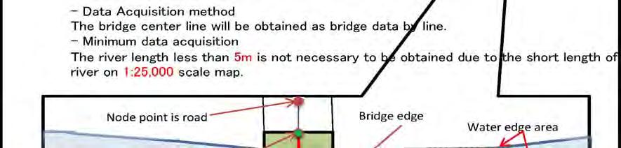
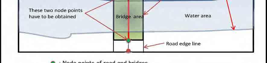
90 Work Manual of Digital Plotting Ver1.2 (1:25,000) 5.5. Bridges


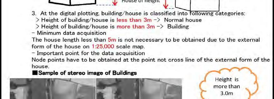
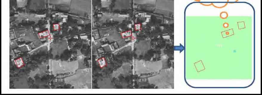
91 Work Manual of Digital Plotting Ver1.2 (1:25,000) 5.6. House
 5.7.")
92 Work Manual of Digital Plotting Ver1.2 (1:25,000) 5.7. House


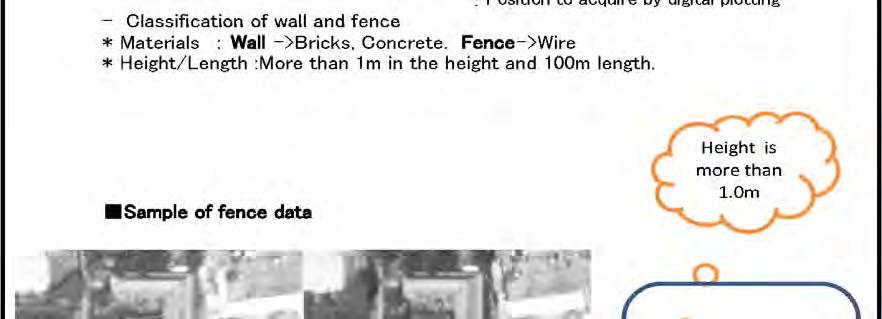
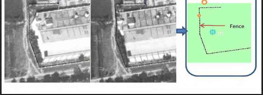
93 Work Manual of Digital Plotting Ver1.2 (1:25,000) 5.8. Wall and Fence


94 Work Manual of Digital Plotting Ver1.2 (1:25,000) 5.9. Vegetation
 5.10. Embankment - 20 -")
95 Work Manual of Digital Plotting Ver1.2 (1:25,000) Embankment


")

96 Work Manual of Digital Plotting Ver1.2 (1:25,000) Power transmission
 5.12.")
97 Work Manual of Digital Plotting Ver1.2 (1:25,000) Spot height


98 Work Manual of Digital Plotting Ver1.2 (1:25,000) Contour
99 Work Manual of Digital Plotting Ver1.2 (1:25,000) 6. Logical check Type of Errors which can be detected by Logical Check by using of Map 3D/AutoCAD; Note: 1) Logical check is not almighty. 2) Error data will not be detected depending on the value of tolerance. 3) Automatic correction is not recommended Software to accomplish Following types of errors can be detected by logical check by using AutoCAD Map 3D. 1. Overshoot (including line crossing without node point) 2. Undershoot 3. Unclosed polygon or poly-line 4. Closed polygon 5. Double object 6. Zero length object 7. Double node point 8. Unconnected poly-line Relation between data type and logical checks is as follow: Name of data Data type Item of logical check All data Polygon Poly-line - Double object - Zero length object House Building Pond Lake Double line river Road Single line river Railway Polygon Poly-line - Double node point - Unclosed polygon - Crossed polygon - Overshoot (including line crossing without node point) - Undershoot - Unconnected poly-line Vegetation boundary Transmission line Poly-line - Overshoot - Undershoot - Unconnected poly-line Contour line Poly-line - Overshoot - Undershoot - Unconnected poly-line
100 Work Manual of Digital Plotting Ver1.2 (1:25,000) 6.2. Overshoot (Including Line Crossing Without Node Point) 1) Sample of error Overshoot Line crossing without node point No node point No node point 2) How to detect the error Image on AutoCAD Map3D
101 Work Manual of Digital Plotting Ver1.2 (1:25,000) Select Map. Select Tool. Then, select Drawing cleanup. Select Select all. Then, select Next
102 Work Manual of Digital Plotting Ver1.2 (1:25,000) Select Break Crossing Objects. Select Add. Select Automatic. Then, select Next. Select Modify original objects. Select Line to Poly-line. Then, select Finish
103 Work Manual of Digital Plotting Ver1.2 (1:25,000) Select Erase Short Object. Select Add. Select Interactive. Set Up Tolerance. Then, select Next. Select Modify original object. Select Line to Poly-line. Then, select Next
104 Work Manual of Digital Plotting Ver1.2 (1:25,000) Set Marker size. Set Marker shape and color. Then, select Finish. Select Mark All. Then, select Close. Error
105 Work Manual of Digital Plotting Ver1.2 (1:25,000) 6.3. Undershoot 1) Sample of error Undershoot 2) How to detect the error Image on AutoCAD Map3D


106 Work Manual of Digital Plotting Ver1.2 (1:25,000) Select Tool. Select Map clean up. Select All. Then, select Next
107 Work Manual of Digital Plotting Ver1.2 (1:25,000) Select Extend Undershoot. Select Add. Set up Tolerance. Select Interactive. Then, select Next. Select Modify original objects. Select Line to poly-line. Then, select Next
108 Work Manual of Digital Plotting Ver1.2 (1:25,000) Set up Marker size Select Shape and color of marker. Then, select Finish. Select Mark all. Then, select Clause
109 Work Manual of Digital Plotting Ver1.2 (1:25,000) 6.4. Unclosed Polygon or Poly-line 1) Sample of error Not close 2) How to detect the error Image on AutoCAD Map3D

110 Work Manual of Digital Plotting Ver1.2 (1:25,000) Open Properties. Select Quick select. Select Closed. Select No. Then, select OK
111 Work Manual of Digital Plotting Ver1.2 (1:25,000) Select Color. Change color to Red or other color
 The color of unclosed poly-line will change")
112 Work Manual of Digital Plotting Ver1.2 (1:25,000) The color of unclosed poly-line will change to red color
113 Work Manual of Digital Plotting Ver1.2 (1:25,000) 6.5. Crossed Polygon 1) Sample of error Crossed polygon 2) How to detect the error Image on AutoCAD Map3D

114 Work Manual of Digital Plotting Ver1.2 (1:25,000) Select Map. Select Tool. Select Drawing cleanup. Select Select all. Then, select Next
115 Work Manual of Digital Plotting Ver1.2 (1:25,000) Select Break crossing object. Select Add. Select Interactive. Then, select Next. Select Modified original objects. Select Line to poly-line. Then, select Next
 Set up Marker size.")

116 Work Manual of Digital Plotting Ver1.2 (1:25,000) Set up Marker size. Select Shape and color of marker. Then, select Finish. Select Mark all. Then, select Close. Error
117 Work Manual of Digital Plotting Ver1.2 (1:25,000) 6.6. Double Object 1) Sample of error Same shape of object locates at same position 2) How to detect the error Image on AutoCAD Map3D
118 Work Manual of Digital Plotting Ver1.2 (1:25,000) Select Map. Select Tool. Then, select Drawing cleanup. Select Select all. Then, select Next
119 Work Manual of Digital Plotting Ver1.2 (1:25,000) Select Delete duplicates. Select Add. Select Interactive. Tolerance is 0. Then, select Next. Select Modify original objects. Select Line to poly-line. Then, select Next
120 Work Manual of Digital Plotting Ver1.2 (1:25,000) Set Marker size. Set Marker shape and color. Then, select Finish. Select Mark all. Then, select Clause. Error
121 Work Manual of Digital Plotting Ver1.2 (1:25,000) 6.7. Zero Length Object 1) Sample of error Zero length object means the starting and ending point of line are located at the same position 2) How to detect the error Image on AutoCAD Map3D
122 Work Manual of Digital Plotting Ver1.2 (1:25,000) Select Map. Select Tool. Then, select Drawing cleanup. Select Select all. Then select Next
 Select Zero length objects. Select Add.")

123 Work Manual of Digital Plotting Ver1.2 (1:25,000) Select Zero length objects. Select Add. Select Interactive. Then, select Next. Select Modify original objects. Select Line to poly-line. Then, select Next
 Set Marker size.")

124 Work Manual of Digital Plotting Ver1.2 (1:25,000) Set Marker size. Set Marker shape and color. Then, select Finish. Select Mark all. Then, select Clause Error
125 Work Manual of Digital Plotting Ver1.2 (1:25,000) 6.8. Double Node Points 1) Sample of error Double node points Double node points In case this point moves, the shape of line become above. 2) How to detect the error Image on AutoCAD Map3D
126 Work Manual of Digital Plotting Ver1.2 (1:25,000) Select Map. Select Tool. Then, select Drawing cleanup. Select Select all. Then, select Next

127 Work Manual of Digital Plotting Ver1.2 (1:25,000) Select Zero length objects. Select Add. Select Interactive. Then, select Next. Select Modify original objects. Select Line to poly-line. Then, select Next
 Set Marker size.")

128 Work Manual of Digital Plotting Ver1.2 (1:25,000) Set Marker size. Set Marker shape and color. Then, select Finish. Select Mark all. Then, select Clause Error
129 Work Manual of Digital Plotting Ver1.2 (1:25,000) 6.9. Unconnected Poly-line 1) Sample of error Unconnected polyline Attention: This error is very difficult to detect by logical check. 2) How to detect the errors Image on AutoCAD Map3D
130 Work Manual of Digital Plotting Ver1.2 (1:25,000) Select Map. Select Tool. Then, select Drawing cleanup. Select Select all. Then, select Next
131 Work Manual of Digital Plotting Ver1.2 (1:25,000) Select Delete objects. Select Add. Select Interactive. Set up Tolerance. Then, select Next. Select Modify original objects. Select Line to poly-line. Then, select Next
132 Work Manual of Digital Plotting Ver1.2 (1:25,000) Set Marker size. Set Marker shape and color. Then, select Finish. Select Mark all. Then, select Clause. Depending on the value of Tolerance, this error can not be detected. Error
133 Work Manual of Digital Plotting Ver1.2 (1:25,000) 7. Visual check There are two methods of visual check of digital plotting data as follows: 7.1 Visual check on screen of digital plotting system The digital plotting data will be shown on the orthophoto image and following check will be executed. - To check the mistakes of code numbers of digital plotting data - To check the horizontal position to be obtained is suitable or not. - To check the lack of data acquisition - To check the node point at the crossing or connecting point made by two polylines. - To check the relation between contour lines and spot height values. 7.2 Visual check on the plotted out paper The digital plotting data with orthophoto image will be plotted out and following check will be executed. - The items mention on 7.1 will be checked using plotted out digital topographic data with orthophoto image. - The inspection results will be recorded in the result table of quality evaluation described in 7.3. It is checked referred to above 7-1 The inspection result is recorded in 7-3(RQE)
134 Work Manual of Digital Plotting Ver1.2 (1:25,000) 7.3 Result table of the quality evaluation (RQE) No. Main-items Sub-item Metal road Check point Code. Extra data Lack data Other RD101 1 Road Un-metal road Brick road Cart track RD102 RD103 RD104 2 Railway Railway line RL201 3 River 4 Lake/Pond 5 Bridges 6 House 7 Fence 8 Vegetation 9 Embankment 10 Power transmission Double line river Single line river Coastline Lake Tank/Pond Bridges Culvert Normal house Building (3m>) Station house Airport house Wall Fence Vegetation boundary Area boundary Vegetation symbol Un-vegetation symbol Embankment(Over 3.0m) Embankment(Below 3.0m) Line Tower (Big) Tower (Small) HF301 HF302 HF303 HF401 HF402 RD501 RD502 PT601 PT602 PT603 PT604 PT305 PT306 HF701 HF702 HF703 HF704 HF801 HF802 PT901 PT902 PT Spot height Spot height RF Contour Contour line (10m) Index contour line (50m) intermediate contour line (5m) RF1102 RF1103 RF
Trimble Geospatial Division Integrated Solutions for Geomatics professions. Volker Zirn Regional Sales Representative
 Trimble Geospatial Division Integrated Solutions for Geomatics professions Volker Zirn Regional Sales Representative 1 Agenda Trimble GeoSpatial Division Airborne System Solutions Trimble Inpho Software
Technical Considerations and Best Practices in Imagery and LiDAR Project Procurement
 Technical Considerations and Best Practices in Imagery and LiDAR Project Procurement Presented to the 2014 WV GIS Conference By Brad Arshat, CP, EIT Date: June 4, 2014 Project Accuracy A critical decision
TRIMBLE BUSINESS CENTER PHOTOGRAMMETRY MODULE
 TRIMBLE BUSINESS CENTER PHOTOGRAMMETRY MODULE WHITE PAPER TRIMBLE GEOSPATIAL DIVISION WESTMINSTER, COLORADO, USA July 2013 ABSTRACT The newly released Trimble Business Center Photogrammetry Module is compatible
Surfaces - Objectives
 Surfaces - Objectives Cover the Basic DTM Point Types Creating a new InRoads Surface Surface processing in InRoads Loading 3D data into a Surface A bit about Surface Properties Overview of the View Surface
Alaska Department of Transportation Roads to Resources Project LiDAR & Imagery Quality Assurance Report Juneau Access South Corridor
 Alaska Department of Transportation Roads to Resources Project LiDAR & Imagery Quality Assurance Report Juneau Access South Corridor Written by Rick Guritz Alaska Satellite Facility Nov. 24, 2015 Contents
Producing Ortho Imagery In ArcGIS. Hong Xu, Mingzhen Chen, Ringu Nalankal
 Producing Ortho Imagery In ArcGIS Hong Xu, Mingzhen Chen, Ringu Nalankal Agenda Ortho imagery in GIS ArcGIS ortho mapping solution Workflows - Satellite imagery - Digital aerial imagery - Scanned imagery
Using ArcGIS Server Data to Assist in Planimetric Update Process. Jim Stout - IMAGIS Rick Hammond Woolpert
 Using ArcGIS Server Data to Assist in Planimetric Update Process Jim Stout - IMAGIS Rick Hammond Woolpert Using ArcGIS Server Data to Assist in Planimetric Update Process Jim Stout - IMAGIS Rick Hammond
New Requirements for the Relief in the Topographic Databases of the Institut Cartogràfic de Catalunya
 New Requirements for the Relief in the Topographic Databases of the Institut Cartogràfic de Catalunya Blanca Baella, Maria Pla Institut Cartogràfic de Catalunya, Barcelona, Spain Abstract Since 1983 the
TBC v License Matrix - Rev 0
 Command Name Viewer (Unlicensed) Base Intermediate Advanced Advanced Drafting Aerial Photogrammetry Data Prep GIS Scanning Tunneling Category 3D Preset Views x x x x General Software 3D View Projection
Should Contours Be Generated from Lidar Data, and Are Breaklines Required? Lidar data provides the most
 Should Contours Be Generated from Lidar Data, and Are Breaklines Required? Lidar data provides the most accurate and reliable representation of the topography of the earth. As lidar technology advances
Licensed Features - Trimble Business Center v3.10
 Licensed Features - Trimble Business Center v3.10 The following table lists the features available in Trimble Business Center based on the installed. Feature No License Base Complete Advanced Photogrammetry
Simply powerful. Pix4Dmapper features the raycloud. Read more on Next generation aerial image processing software
 Next generation aerial image processing software Simply powerful Pix4D is your solution to convert thousands of aerial images taken by lightweight UAV or aircraft into georeferenced 2D mosaics and 3D surface
MASI: Modules for Aerial and Satellite Imagery. Version 3.0 Aerial Modules. Tutorial
 MASI: Modules for Aerial and Satellite Imagery Version 3.0 Aerial Modules Tutorial VisionOnSky Co., Ltd. www.visiononsky.com File Version: v1.0 Sept. 12, 2018 Special Notes: (1) Before starting the tour
PhotoScan. Fully automated professional photogrammetric kit
 PhotoScan Fully automated professional photogrammetric kit Agisoft PhotoScan is a stand-alone photogrammetric software solution for automatic generation of dense point clouds, textured polygonal models,
trimble unmanned aircraft systems
 trimble unmanned aircraft systems FOR SURVEYING and MAPPING TRIMBLE UAS AERIAL IMAGING solution: INDUSTRY-LEADING UAS MAPPING SOLUTIONS FOR ALL YOUR APPLICATION NEEDS Trimble prides itself on being a leader
TrueOrtho with 3D Feature Extraction
 TrueOrtho with 3D Feature Extraction PCI Geomatics has entered into a partnership with IAVO to distribute its 3D Feature Extraction (3DFE) software. This software package compliments the TrueOrtho workflow
TcpMDT. Digital Terrain Model Version 7.5. TcpMDT
 Digital Terrain Model Version 7.5 Versions and Modules PROFESSIONAL STANDARD IMAGES SURVEYING POINT CLOUD Product Features STANDARD Surveying Points Management Digital Terrain Model Contours Terrain Cross
PRODUCT BROCHURE IMAGESTATION HIGH VOLUME PHOTOGRAMMETRY AND PRODUCTION MAPPING
 PRODUCT BROCHURE IMAGESTATION HIGH VOLUME PHOTOGRAMMETRY AND PRODUCTION MAPPING UNPARALLELED PROCESSING, ACCURATE RESULTS FOR CAD AND GIS-BASED WORKFLOWS The ImageStation software suite enables digital
Guideline for Importing Survey Data into Bentley Power InRoads v8i SS2
 Guideline for Importing Survey Data into Bentley Power InRoads v8i SS2 I. REQUIREMENTS from the Geomatics/Survey Function: 1. A CAD-only drawing in.dwg file format ver. 2013, (that can be created natively
Grading and Volumes CHAPTER INTRODUCTION OBJECTIVES
 CHAPTER 10 Grading and Volumes INTRODUCTION AutoCAD Civil 3D uses surface breaklines, cogo points, contours, feature lines, and grading objects to create a surface design. There are numerous ways to grade
LiDAR & Orthophoto Data Report
 LiDAR & Orthophoto Data Report Tofino Flood Plain Mapping Data collected and prepared for: District of Tofino, BC 121 3 rd Street Tofino, BC V0R 2Z0 Eagle Mapping Ltd. #201 2071 Kingsway Ave Port Coquitlam,
TERRESTRIAL AND NUMERICAL PHOTOGRAMMETRY 1. MID -TERM EXAM Question 4
 TERRESTRIAL AND NUMERICAL PHOTOGRAMMETRY 1. MID -TERM EXAM Question 4 23 November 2001 Two-camera stations are located at the ends of a base, which are 191.46m long, measured horizontally. Photographs
Hamilton County Enhances GIS Base Mapping with 1-foot Contours
 Hamilton County Enhances GIS Base Mapping with 1-foot Contours Presented by Larry Stout, Hamilton County GIS Manager Brad Fugate, Woolpert Inc. Today s Presentation Hamilton County s 2004 Base Mapping
Tutorial (Beginner level): Orthomosaic and DEM Generation with Agisoft PhotoScan Pro 1.3 (with Ground Control Points)
: Orthomosaic and DEM Generation with Agisoft PhotoScan Pro 1.3 (with Ground Control Points)") Tutorial (Beginner level): Orthomosaic and DEM Generation with Agisoft PhotoScan Pro 1.3 (with Ground Control Points) Overview Agisoft PhotoScan Professional allows to generate georeferenced dense point
Tutorial (Beginner level): Orthomosaic and DEM Generation with Agisoft PhotoScan Pro 1.3 (with Ground Control Points) Overview Agisoft PhotoScan Professional allows to generate georeferenced dense point
Surveying like never before
 CAD functionalities GCP Mapping and Aerial Image Processing Software for Land Surveying Specialists Surveying like never before www.3dsurvey.si Modri Planet d.o.o., Distributors: info@3dsurvey.si +386
Tutorial (Beginner level): Orthomosaic and DEM Generation with Agisoft PhotoScan Pro 1.3 (without Ground Control Points)
: Orthomosaic and DEM Generation with Agisoft PhotoScan Pro 1.3 (without Ground Control Points)") Tutorial (Beginner level): Orthomosaic and DEM Generation with Agisoft PhotoScan Pro 1.3 (without Ground Control Points) Overview Agisoft PhotoScan Professional allows to generate georeferenced dense point
Tutorial (Beginner level): Orthomosaic and DEM Generation with Agisoft PhotoScan Pro 1.3 (without Ground Control Points) Overview Agisoft PhotoScan Professional allows to generate georeferenced dense point
Feature Extraction from Imagery & Lidar. Kurt Schwoppe, Esri Mark Romero, Esri Gregory Bacon, Fairfax County
 Feature Extraction from & Lidar Kurt Schwoppe, Esri Mark Romero, Esri Gregory Bacon, Fairfax County Today s Speakers Image Processing Experts and Good Colleagues Kurt Schwoppe Industry Lead Esri Mark Romero
Point Cloud Classification
 Point Cloud Classification Introduction VRMesh provides a powerful point cloud classification and feature extraction solution. It automatically classifies vegetation, building roofs, and ground points.
Experiments on Generation of 3D Virtual Geographic Environment Based on Laser Scanning Technique
 Experiments on Generation of 3D Virtual Geographic Environment Based on Laser Scanning Technique Jie Du 1, Fumio Yamazaki 2 Xiaoyong Chen 3 Apisit Eiumnoh 4, Michiro Kusanagi 3, R.P. Shrestha 4 1 School
3D Model - Data Transfer Guide
 Introduction 3D Model - The Leicester City model is a photogrammetric survey based 3D representation of 380ha of Leicester s Central Regeneration Area. The model is to be: Used for marketing and inward
CREATING CUSTOMIZED SPATIAL MODELS WITH POINT CLOUDS USING SPATIAL MODELER OPERATORS TO PROCESS POINT CLOUDS IN IMAGINE 2014
 CREATING CUSTOMIZED SPATIAL MODELS WITH POINT CLOUDS USING SPATIAL MODELER OPERATORS TO PROCESS POINT CLOUDS IN IMAGINE 2014 White Paper December 22, 2016 Contents 1. Introduction... 3 2. ERDAS IMAGINE
Mosaic Tutorial: Advanced Workflow
 Mosaic Tutorial: Advanced Workflow This tutorial demonstrates how to mosaic two scenes with different color variations. You will learn how to: Reorder the display of the input scenes Achieve a consistent
Exercise 1: Introduction to ILWIS with the Riskcity dataset
 Exercise 1: Introduction to ILWIS with the Riskcity dataset Expected time: 2.5 hour Data: data from subdirectory: CENN_DVD\ILWIS_ExerciseData\IntroRiskCity Objectives: After this exercise you will be able
CHAPTER 10. Digital Mapping and Earthwork
 CHAPTER 10 Digital Mapping and Earthwork www.terrainmap.com/rm22.html CE 316 March 2012 348 10.1 Introduction 349 10.2 Single Images 10.2.1 Rectified Photograph With a single photograph, X,Y data can be
Creating raster DEMs and DSMs from large lidar point collections. Summary. Coming up with a plan. Using the Point To Raster geoprocessing tool
 Page 1 of 5 Creating raster DEMs and DSMs from large lidar point collections ArcGIS 10 Summary Raster, or gridded, elevation models are one of the most common GIS data types. They can be used in many ways
QUALITY CONTROL METHOD FOR FILTERING IN AERIAL LIDAR SURVEY
 QUALITY CONTROL METHOD FOR FILTERING IN AERIAL LIDAR SURVEY Y. Yokoo a, *, T. Ooishi a, a Kokusai Kogyo CO., LTD.,Base Information Group, 2-24-1 Harumicho Fuchu-shi, Tokyo, 183-0057, JAPAN - (yasuhiro_yokoo,
Leica Photogrammetry Suite Automatic Terrain Extraction
 Leica Photogrammetry Suite Automatic Terrain Extraction Copyright 2006 Leica Geosystems Geospatial Imaging, LLC All rights reserved. Printed in the United States of America. The information contained in
2. POINT CLOUD DATA PROCESSING
 Point Cloud Generation from suas-mounted iphone Imagery: Performance Analysis A. D. Ladai, J. Miller Towill, Inc., 2300 Clayton Road, Suite 1200, Concord, CA 94520-2176, USA - (andras.ladai, jeffrey.miller)@towill.com
Vegetation height maps derived from digital elevation models the next innovation in the production of orienteering maps?
 Vegetation height maps derived from digital elevation models the next innovation in the production of orienteering maps? Development of Orienteering Maps. 1. Revolution 20 years ago: Digital Cartography
Digital Terrain Model V 6.5
 TCP MDT Digital Terrain Model V 6.5 Professional Version Introduction The Professional Version is designed to assist users in all the phases of carrying out a Surveying or Civil Engineering project. Its
Final Report for the Niagara Peninsula Conservation Authority 2010 Update to 1m Contour Supporting Digital Terrain Model for Niagara Watershed
 Final Report for the Niagara Peninsula Conservation Authority 2010 Update to 1m Contour Supporting Digital Terrain Model for Niagara Watershed Date: April 9, 2013 TABLE OF CONTENTS 1. PROJECT BACKGROUND...
Iowa Department of Transportation Office of Design. Photogrammetric Mapping Specifications
 Iowa Department of Transportation Office of Design Photogrammetric Mapping Specifications March 2015 1 Purpose of Manual These Specifications for Photogrammetric Mapping define the standards and general
Training i Course Remote Sensing Basic Theory & Image Processing Methods September 2011
 Training i Course Remote Sensing Basic Theory & Image Processing Methods 19 23 September 2011 Geometric Operations Michiel Damen (September 2011) damen@itc.nl ITC FACULTY OF GEO-INFORMATION SCIENCE AND
SEAMLESS MAPPING SYSTEM FOR HIGH RESOLUTION IMAGERY
 SEAMLESS MAPPING SYSTEM FOR HIGH RESOLUTION IMAGERY Haibin Ai a,b *, Jianqing Zhang a, Yansong Duan b a School of Remote Sensing and Information Engineering, Wuhan University, 430074 Wuhan, Hubei, China
Live (2.5D) DEM Editing Geomatica 2015 Tutorial
 DEM Editing Geomatica 2015 Tutorial") Live (2.5D) DEM Editing Geomatica 2015 Tutorial The DEM Editing tool is a quick and easy tool created to smooth out irregularities and create a more accurate model, and in turn, generate more accurate
Live (2.5D) DEM Editing Geomatica 2015 Tutorial The DEM Editing tool is a quick and easy tool created to smooth out irregularities and create a more accurate model, and in turn, generate more accurate
Merging LiDAR Data with Softcopy Photogrammetry Data
 Merging LiDAR Data with Softcopy Photogrammetry Data Cindy McCallum WisDOT\Bureau of Technical Services Surveying & Mapping Section Photogrammetry Unit Overview Terms and processes Why use data from LiDAR
AutoCAD Civil 3D 2011 ESSENTIALS
 AutoCAD Civil 3D 2011 ESSENTIALS SDC PUBLICATIONS www.sdcpublications.com Schroff Development Corporation Table of Contents Table of Contents Preface...ix Module 1 The AutoCAD Civil 3D Interface... 1-1
Aspects on True-Orthophoto Production
 Photogrammetric Week '03 Dieter Fritsch (Ed.) Wichmann Verlag, Heidelberg, 2003 Braun 205 Aspects on True-Orthophoto Production JOSEF BRAUN, INPHO GmbH, Stuttgart ABSTRACT In many occasions orthophotos
2011 Bentley Systems, Incorporated. Bentley Descartes V8i (SELECTseries 3) Advancing Information Modeling For Intelligent Infrastructure
 Advancing Information Modeling For Intelligent Infrastructure") Bentley Descartes V8i (SELECTseries 3) Advancing Information Modeling For Intelligent Infrastructure What is Bentley Descartes? Image Processing Raster Geo-Referencing Advanced raster transformation (warping,
Bentley Descartes V8i (SELECTseries 3) Advancing Information Modeling For Intelligent Infrastructure What is Bentley Descartes? Image Processing Raster Geo-Referencing Advanced raster transformation (warping,
GEO 6895: Airborne laser scanning - workflow, applications, value. Christian Hoffmann
 GEO 6895: Airborne laser scanning - workflow, applications, value. Christian Hoffmann Agenda Why LiDAR? The value of an end-to-end workflow The Trimble AX-Series Data processing & modelling Information
Lecture 4: Digital Elevation Models
 Lecture 4: Digital Elevation Models GEOG413/613 Dr. Anthony Jjumba 1 Digital Terrain Modeling Terms: DEM, DTM, DTEM, DSM, DHM not synonyms. The concepts they illustrate are different Digital Terrain Modeling
Sasanka Madawalagama Geoinformatics Center Asian Institute of Technology Thailand
 Sasanka Madawalagama Geoinformatics Center Asian Institute of Technology Thailand This learning material was not prepared by ADB. The views expressed in this document are the views of the author/s and
HEC-RAS 5.0 Training New Zealand Workshop Guide
 HEC-RAS 5.0 Training New Zealand Workshop Guide Prepared by: Krey Price Surface Water Solutions 57 Bromfield Drive Kelmscott WA 6111 Australia Tel. +61 400 367 542 e-mail: info@surfacewater.biz website:
APPLICATION OF DIGITAL PHOTOGRAMMETRY AND AUTOCAD TO SUPPORT OF HISTORICAL BUILDINGS
 APPLICATION OF DIGITAL PHOTOGRAMMETRY AND AUTOCAD TO SUPPORT OF HISTORICAL BUILDINGS SEYED YOUSEF SADJADI Department of Geography and Geomatics Centre for Geosciences University of Glasgow University Avenue,
LASERDATA LIS build your own bundle! LIS Pro 3D LIS 3.0 NEW! BETA AVAILABLE! LIS Road Modeller. LIS Orientation. LIS Geology.
 LIS 3.0...build your own bundle! NEW! LIS Geology LIS Terrain Analysis LIS Forestry LIS Orientation BETA AVAILABLE! LIS Road Modeller LIS Editor LIS City Modeller colors visualization I / O tools arithmetic
Welcome to IMAGIN. June 18, 2018
 Welcome to IMAGIN June 18, 2018 Battle Royale: Pix4D vs Drone2Map A Comparison of Drone Processing Softwares as applied to GIS and a Fly-Through of UAV/GIS workflows 2 Presentation Flight Plan 1. Introductions
Surface and Terrain Models
 Advanced Matching Techniques for High Precision Surface and Terrain Models Introduction Comeback of image matching for DTM & DSM generation Very few professional tools for DSM generation from image matching
PhotoScan. Fully automated professional photogrammetric kit
 PhotoScan Fully automated professional photogrammetric kit Agisoft PhotoScan is a stand-alone photogrammetric software solution for automatic generation of dense point clouds, textured polygonal models,
2010 LiDAR Project. GIS User Group Meeting June 30, 2010
 2010 LiDAR Project GIS User Group Meeting June 30, 2010 LiDAR = Light Detection and Ranging Technology that utilizes lasers to determine the distance to an object or surface Measures the time delay between
12D Solutions Pty Ltd CIVIL AND SURVEYING SOFTWARE
 Civil and Surveying Software Course Notes CIVIL AND SURVEYING SOFTWARE THE 12D PERSPECTIVE River Interfaces HEC RAS, ISIS, Mike11 and XP SWMM 12d Solutions Pty Limited ACN 056 019 713 Phone: +61 (2) 9970
AUTOMATIC EXTRACTION OF TERRAIN SKELETON LINES FROM DIGITAL ELEVATION MODELS
 AUTOMATIC EXTRACTION OF TERRAIN SKELETON LINES FROM DIGITAL ELEVATION MODELS F. Gülgen, T. Gökgöz Yildiz Technical University, Department of Geodetic and Photogrammetric Engineering, 34349 Besiktas Istanbul,
AEC Logic. AEC Terrain. A program to manage earth works in a construction project. Yudhishtirudu Gaddipati 29-Jun-13
 AEC Logic AEC Terrain A program to manage earth works in a construction project Yudhishtirudu Gaddipati 29-Jun-13 Contents 1 Introduction:... 5 2 Program Launch... 5 2.1 How to Launch Program... 5 2.2
LiDAR QA/QC - Quantitative and Qualitative Assessment report -
 LiDAR QA/QC - Quantitative and Qualitative Assessment report - CT T0009_LiDAR September 14, 2007 Submitted to: Roald Haested Inc. Prepared by: Fairfax, VA EXECUTIVE SUMMARY This LiDAR project covered approximately
Files Used in this Tutorial
 RPC Orthorectification Tutorial In this tutorial, you will use ground control points (GCPs), an orthorectified reference image, and a digital elevation model (DEM) to orthorectify an OrbView-3 scene that
ABSTRACT 1. INTRODUCTION
 Published in SPIE Proceedings, Vol.3084, 1997, p 336-343 Computer 3-d site model generation based on aerial images Sergei Y. Zheltov, Yuri B. Blokhinov, Alexander A. Stepanov, Sergei V. Skryabin, Alexander
Visualizing 2D Data in a 3D World
 Visualizing 2D Data in a 3D World Karl Kliparchuk, M.Sc., GISP, and Brendan Walashek, B.Sc. McElhanney Consulting Services Ltd. Email: kkliparchuk@mcelhanney.com and bwalashek@mcelhanney.com Agenda A Quick
Files Used in this Tutorial
 RPC Orthorectification Tutorial In this tutorial, you will use ground control points (GCPs), an orthorectified reference image, and a digital elevation model (DEM) to orthorectify an OrbView-3 scene that
MATCH-AT: Recent Developments and Performance
 'Photogrammetric Week 01' D. Fritsch & R. Spiller, Eds. Wichmann Verlag, Heidelberg 2001. Sigle, Heuchel 189 MATCH-AT: Recent Developments and Performance MANFRED SIGLE, TOBIAS HEUCHEL, Stuttgart ABSTRACT
3DReshaper Help DReshaper Beginner's Guide. Surveying
 3DReshaper Beginner's Guide Surveying 1 of 29 Cross sections Exercise: Tunnel analysis Surface analysis Exercise: Complete analysis of a concrete floor Surveying extraction Exercise: Automatic extraction
SPOT-1 stereo images taken from different orbits with one month difference
 DSM Generation Almost all HR sensors are stereo capable. Some can produce even triplettes within the same strip (facilitating multi-image matching). Mostly SPOT (1-5) used for stereo and Ikonos (in spite
2011 Bentley Systems, Incorporated. Bentley Descartes V8i Advancing Information Modeling For Intelligent Infrastructure
 Bentley Descartes V8i Advancing Information Modeling For Intelligent Infrastructure Agenda Why would you need Bentley Descartes? What is Bentley Descartes? Advanced Point Cloud Workflows Advanced Terrain
TCP MDT Digital Terrain Model - V7.5
 TCP MDT Digital Terrain Model - V7.5 Standard Version Introduction The Standard Version is suitable for carrying out all kinds of topographical survey projects, terrain profiles, volume calculations etc.
2-4 April 2019 Taets Art and Event Park, Amsterdam CLICK TO KNOW MORE
 Co-Host Host 2-4 April 2019 Taets Art and Event Park, Amsterdam CLICK TO KNOW MORE Presentation Outline review modern survey methodologies available to support railway requirements measuring everything
Image Services for Elevation Data
 Image Services for Elevation Data Peter Becker Need for Elevation Using Image Services for Elevation Data sources Creating Elevation Service Requirement: GIS and Imagery, Integrated and Accessible Field
v SMS 11.1 Tutorial Scatter Data - TINs Requirements Scatter Module Map Module Time minutes Prerequisites None Objectives
 v. 11.1 SMS 11.1 Tutorial Scatter Data - TINs Objectives This workshop covers the basics of working with TINs (triangulated irregular networks) using the scatter module of SMS. We will cover importing
WORKFLOW AND QUALITY CONTROL TO GENERATE DEM AND DSM BY AERIAL PHOTOGRAMMETRY
 WORKFLOW AND QUALITY CONTROL TO GENERATE DEM AND DSM BY AERIAL PHOTOGRAMMETRY JIA Qiuying CAO Haitang JIANG Decai ZHU Rong Surveying and Mapping Engineering Branch of Aerophotogrammetry and Remote Sensing
DIGITAL TERRAIN MODELS
 DIGITAL TERRAIN MODELS 1 Digital Terrain Models Dr. Mohsen Mostafa Hassan Badawy Remote Sensing Center GENERAL: A Digital Terrain Models (DTM) is defined as the digital representation of the spatial distribution
v Scatter Data TINs SMS 12.3 Tutorial Requirements Scatter Module Map Module Time minutes Prerequisites None Objectives
 v. 12.3 SMS 12.3 Tutorial Objectives This tutorial covers the basics of working with TINs (triangulated irregular networks) using the scatter module of SMS, including: importing TIN data, editing and filtering
Chapters 1 7: Overview
 Chapters 1 7: Overview Photogrammetric mapping: introduction, applications, and tools GNSS/INS-assisted photogrammetric and LiDAR mapping LiDAR mapping: principles, applications, mathematical model, and
v Importing Rasters SMS 11.2 Tutorial Requirements Raster Module Map Module Mesh Module Time minutes Prerequisites Overview Tutorial
 v. 11.2 SMS 11.2 Tutorial Objectives This tutorial teaches how to import a Raster, view elevations at individual points, change display options for multiple views of the data, show the 2D profile plots,
Photogrammetry: DTM Extraction & Editing
 Photogrammetry: DTM Extraction & Editing How can one determine the x, y, and z of a location? Approaches to DTM Extraction Ground surveying Digitized topographic maps Traditional photogrammetry Hardcopy
Assimilation of Break line and LiDAR Data within ESRI s Terrain Data Structure (TDS) for creating a Multi-Resolution Terrain Model
 for creating a Multi-Resolution Terrain Model") Assimilation of Break line and LiDAR Data within ESRI s Terrain Data Structure (TDS) for creating a Multi-Resolution Terrain Model Tarig A. Ali Department of Civil Engineering American University of Sharjah,
Assimilation of Break line and LiDAR Data within ESRI s Terrain Data Structure (TDS) for creating a Multi-Resolution Terrain Model Tarig A. Ali Department of Civil Engineering American University of Sharjah,
SimActive and PhaseOne Workflow case study. By François Riendeau and Dr. Yuri Raizman Revision 1.0
 SimActive and PhaseOne Workflow case study By François Riendeau and Dr. Yuri Raizman Revision 1.0 Contents 1. Introduction... 2 1.1. Simactive... 2 1.2. PhaseOne Industrial... 2 2. Testing Procedure...
Journal Online Jaringan COT POLIPD (JOJAPS) Accuracy Assessment of Height Coordinate Using Unmanned Aerial Vehicle Images Based On Leveling Height
 Accuracy Assessment of Height Coordinate Using Unmanned Aerial Vehicle Images Based On Leveling Height") JOJAPS eissn 2504-8457 Abstract Journal Online Jaringan COT POLIPD (JOJAPS) Accuracy Assessment of Height Coordinate Using Unmanned Aerial Vehicle Images Based On Leveling Height Syamsul Anuar Bin Abu
JOJAPS eissn 2504-8457 Abstract Journal Online Jaringan COT POLIPD (JOJAPS) Accuracy Assessment of Height Coordinate Using Unmanned Aerial Vehicle Images Based On Leveling Height Syamsul Anuar Bin Abu
TerraScan Tool Guide
 TerraScan Main Toolbox General Toolbar Draw Toolbar Groups Toolbar Vectorize Towers Toolbar Road Toolbar Buildings Toolbar Building Edges Toolbar View Laser Toolbar Model Toolbar Vectorize Wires Toolbar
A Method to Create a Single Photon LiDAR based Hydro-flattened DEM
 A Method to Create a Single Photon LiDAR based Hydro-flattened DEM Sagar Deshpande 1 and Alper Yilmaz 2 1 Surveying Engineering, Ferris State University 2 Department of Civil, Environmental, and Geodetic
Contents of Lecture. Surface (Terrain) Data Models. Terrain Surface Representation. Sampling in Surface Model DEM
 Data Models. Terrain Surface Representation. Sampling in Surface Model DEM") Lecture 13: Advanced Data Models: Terrain mapping and Analysis Contents of Lecture Surface Data Models DEM GRID Model TIN Model Visibility Analysis Geography 373 Spring, 2006 Changjoo Kim 11/29/2006 1
Lecture 13: Advanced Data Models: Terrain mapping and Analysis Contents of Lecture Surface Data Models DEM GRID Model TIN Model Visibility Analysis Geography 373 Spring, 2006 Changjoo Kim 11/29/2006 1
LIDAR MAPPING FACT SHEET
 1. LIDAR THEORY What is lidar? Lidar is an acronym for light detection and ranging. In the mapping industry, this term is used to describe an airborne laser profiling system that produces location and
v TUFLOW-2D Hydrodynamics SMS Tutorials Time minutes Prerequisites Overview Tutorial
 v. 12.2 SMS 12.2 Tutorial TUFLOW-2D Hydrodynamics Objectives This tutorial describes the generation of a TUFLOW project using the SMS interface. This project utilizes only the two dimensional flow calculation
PRODUCT DESCRIPTION PRODUCT DESCRIPTION
 IMAGESTATION PRODUCT DESCRIPTION PRODUCT DESCRIPTION IMAGESTATION FAMILY OF PRODUCTS ImageStation includes applications for your entire production workflow including project creation, orientation and triangulation,
Accuracy Assessment of POS AVX 210 integrated with the Phase One ixu150
 White Paper 3/17/2016 Accuracy Assessment of POS AVX 210 integrated with the Phase One ixu150 Omer Mian, Joe Hutton, Greg Lipa, James Lutes, Damir Gumerov, Srdjan Sobol Applanix, William Chan - GeoPixel
Intelligent photogrammetry. Agisoft
 Intelligent photogrammetry Agisoft Agisoft Metashape is a cutting edge software solution, with its engine core driving photogrammetry to its ultimate limits, while the whole system is designed to deliver
AutoCAD Civil 3D 2014 for Surveyors
 AutoCAD Civil 3D 2014 for Surveyors SDC P U B L I C AT I O N S Better Textbooks. Lower Prices. www.sdcpublications.com Powered by TCPDF (www.tcpdf.org) Visit the following websites to learn more about
United State Department of Agriculture Forest Service Southwestern Region\Region 3 CAD Standards Manual Version 1.0
 United State Department of Agriculture Forest Service Southwestern Region\Region 3 CAD Standards Manual Version 1.0 3/12/2010 Prepared for: Bart Matthews US Forest Service Southwestern Regional Office
PhotoMesh v7.0. What s New in PhotoMesh v7.0
 PhotoMesh v7.0 PhotoMesh v7.0 fully automates the generation of high-resolution, textured, 3D mesh models from standard 2D photographs. Combining any number of photographs, in a wide range of formats and
2. AREAL PHOTOGRAPHS, SATELLITE IMAGES, & TOPOGRAPHIC MAPS
 LAST NAME (ALL IN CAPS): FIRST NAME: 2. AREAL PHOTOGRAPHS, SATELLITE IMAGES, & TOPOGRAPHIC MAPS Instructions: Refer to Exercise 3 in your Lab Manual on pages 47-64 to answer the questions in this work
OrthoPro: The Z/I Imaging 1 Approach for the Orthophoto Production
 Madani 247 OrthoPro: The Z/I Imaging 1 Approach for the Orthophoto Production MOSTAFA MADANI, Huntsville ABSTRACT The latest product from Z/I Imaging, ImageStation OrthoPro, provides customers with unparalleled
High resolution satellite images orthoprojection using dense DEM
 See discussions, stats, and author profiles for this publication at: https://www.researchgate.net/publication/252229019 High resolution satellite images orthoprojection using dense DEM Article in Proceedings
Digital photogrammetry project with very high-resolution stereo pairs acquired by DigitalGlobe, Inc. satellite Worldview-2
 White PAPER Greater area of the City of La Paz, Bolivia Digital photogrammetry project with very high-resolution stereo pairs acquired by DigitalGlobe, Inc. satellite Worldview-2 By: Engineers Nelson Mattie,
SURVEY 3.0. Innovative field solutions for Surveyors X PAD. works when you do
 Innovative field solutions for Surveyors works when you do X PAD INNOVATIVE FIELD SOLUTION FOR SURVEYORS The software for survey, stakeout and control, ensuring productivity and flexibility in the field,