Chapters 1 9: Overview
|
|
|
- Adela Whitehead
- 5 years ago
- Views:
Transcription
1 Chapters 1 9: Overview Chapter 1: Introduction Chapters 2 4: Data acquisition Chapters 5 9: Data manipulation Chapter 5: Vertical imagery Chapter 6: Image coordinate measurements and refinements Chapters 7 9: Mathematical model and bundle block adjustment This chapter will cover the incorporation of GNSS/INS position and attitude information in the photogrammetric reconstruction procedure. 1
2 CE 59700: Chapter 10 Photogrammetric Geo-Referencing 2
3 Overview Introduction Geo-Referencing Alternatives: Indirect geo-referencing Integrated Sensor Orientation (ISO) Direct geo-referencing Direct Geo-Referencing: Operational Example Terrestrial Mobile Mapping Systems (MMS) Accuracy Analysis of Different Geo-Referencing Techniques Concluding Remarks 3
4 b r a r c ab Notation Stands for the coordinates of point a relative to point b this vector is defined relative to the coordinate system associated with point b. Stands for the components of the vector ab relative to the coordinate system denoted by c. b R a Stands for the rotation matrix that transforms a vector defined relative to the coordinate system denoted by a into a vector defined relative to the coordinate system denoted by b. 4
5 Notation a z c b y c b r a x c c r ab b a 5
6 Notation b R a 6
 Object")


7 Photogrammetric Reconstruction Conjugate Points a a Camera Calibration (IOPs) Object Point (A) Camera Geo-referencing (EOPs) The interior orientation parameters of the involved cameras have to be known. The position and the orientation of the camera stations have to be known. 7
8 Photogrammetry The objective of photogrammetry is to transform centrally projected images into a three-dimensional model, which can be used to plot an orthogonal map. The three-dimensional model can be obtained through: Interior Orientation Defined through a calibration procedure Exterior Orientation Defined through a geo-referencing procedure 8
9 Photogrammetry 9
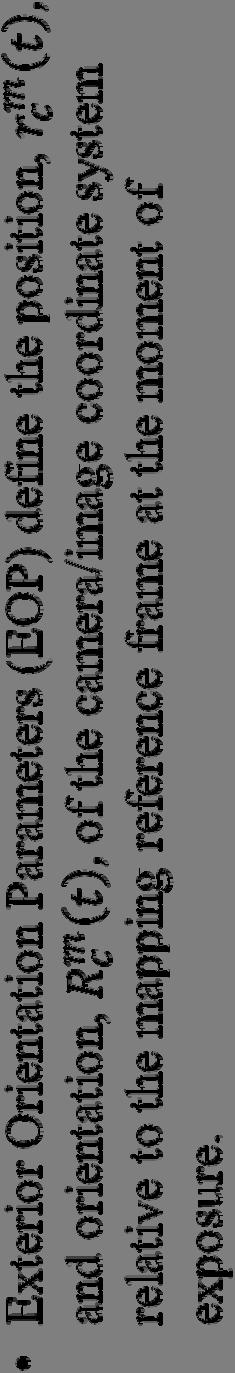
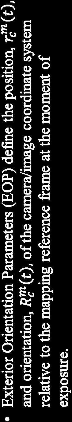
10 Interior Orientation Purpose: Reconstruct the bundle of light rays (as defined by the perspective center and the image points) in such a way that it is similar to the incident bundle onto the camera at the moment of exposure. Interior orientation is defined by the position of the perspective center w.r.t. the image coordinate system (x p, y p, c). Another component of the interior orientation is the distortion parameters. 10
11 Interior Orientation d c b a Image Space d c b a Image Space Lens Lens A B C Object Space D IO: Target Function 11
, Indoor camera calibration, and Analytical Camera In-situ camera calibration.")
12 Interior Orientation Parameters Alternative procedures for estimating the Interior Orientation Parameters (IOPs) include: Laboratory camera calibration (Multi-collimators), Indoor camera calibration, and Analytical Camera In-situ camera calibration. Calibration 12
13 Geo-Referencing Geo-referencing: the process of relating the image and ground coordinate systems. Defines the position and orientation information of the camera (image bundle) at the moment of exposure. Traditionally, the geo-referencing parameters are obtained using Ground Control Points (GCPs) in a bundle adjustment procedure. Indirect geo-referencing 13
14 Geo-Referencing Z G R(,, ) z pc y x Y G Z o X o Y o X G 14
15 Geo-Referencing R m c (t) c-frame r m (t) c m-frame 15
16 Indirect Geo-Referencing: Single Image exterior orientation interior orientation Single Photo Resection Procedure 16

17 Indirect Geo-Referencing: Image Block Ground Control Points Tie Points Bundle Adjustment Procedure 17
18 Indirect Geo-Referencing Within the indirect geo-referencing procedure, the Exterior Orientation Parameters (EOPs) are determined in such a way that: Conjugate light rays intersect as well as possible, and Light rays, which correspond to ground control points, pass as close as possible to their object space locations. In other words, the EOPs are indirectly determined to satisfy the above mentioned objectives. 18
19 Reconstruction with Indirect Geo-Referencing Interpolation Process 19
20 Direct Geo-Referencing Nowadays, direct geo-referencing is possible using an integrated DGNSS/INS. The position and orientation of each image is directly determined using onboard sensors without the need for GCPs. Economic advantages, especially in areas with poor or sparse control Precaution: Consider the spatial and temporal relationship between the involved sensors and derived measurements, respectively Calibrating the entire system is essential. 20
21 Direct Geo-Referencing Extrapolation Process 21

22 Direct Geo-Referencing Ground Control Points Tie Points 22
23 Direct Geo-Referencing r ( t) r ( t) R ( t) m c m b m b r b c IMU b-frame GNSS antenna Camera position GNSS/INS position GNSS/INS attitude Calibration R ( t) R ( t) m c m b R b c R m b (t) b r c b R c Camera attitude GNSS/INS attitude Calibration r m (t) b r m c (t ) R m c c-frame (t) m-frame 23
24 Direct Geo-Referencing: Single Image b R c IMU Body Frame R m b ( t) r b c Camera Frame R m b (t) r m (t) b i S i R ( t) R m b b c r i c m r I I Mapping Coordinate Frame With direct geo-referencing, can we reconstruct the object space from a single image? 24
25 Direct Geo-Referencing: Single Image m r I m r b i S (t) m r I m r ( t) b m i R b ( t)[ S b R is the position vector of point (I) in the mapping frame (m-frame), is the interpolated position vector of the IMU b-frame in the m-frame, is a scale factor specific to one-image/one-point combination, c r i c r b c ] m R b () t is the interpolated rotation matrix between the IMU b-frame and the m-frame, (t) b R c c r i b r c is the time of exposure (i.e., the time of capturing the images), is the differential rotation between the camera frame (c-frame) and the b-frame, is the position vector of point (i) in the camera frame (c-frame), and is the offset between the camera and the IMU in the b-frame. 25
26 Direct Geo-Referencing: Land-based System Digital camera GNSS antenna INS Direct geo-referencing in practice 26

27 Direct Geo-Referencing: Airborne System Direct geo-referencing in practice 27
28 Direct Geo-Referencing: Airborne System GNSS Antenna INS PC Two Base Stations Camera GNSS Receiver 28


29 Direct Geo-Referencing GNSS Antenna Imaging PC Trimble 4000SSI INS/GNSS PC BigShot Hasselblad Camera LN-100 GNSS Base Station Hardware Configuration 29
30 GNSS Antenna Camera Integrated Sensor Orientation (ISO) GNSS-Controlled Aerial Triangulation 30
31 GNSS and Photogrammetry Role of GNSS in various photogrammetric activities: Provide ground coordinates for control points Pin-point photography to precisely execute a flight mission Provide direct observations of the position of the projection center for bundle block adjustment The following slides will be concentrating on the last item, namely: Derive the ground coordinates of the perspective center at the moment of exposure GNSS-controlled aerial triangulation 31
32 GNSS-Controlled Aerial Triangulation Advantages: GNSS observations at the aircraft can stabilize the heights along as well as across the strips. GNSS observations at the aircraft would reduce (or even eliminate) the need for ground control points. For normal-case photography over flat terrain, GNSS observations at the aircraft would decouple the correlation between the principal distance and the flying height (if we are performing self calibration). 32
33 GNSS-Controlled Aerial Triangulation Block coverage Control point The vertical accuracy within a block, which has control only at its corners, is worse at the center of the block. The vertical accuracy will deteriorate as the size of the block increases. Incorporating the GNSS observations at the exposure stations in the bundle adjustment procedure (GNSS-controlled aerial triangulation) would improve the vertical accuracy within the block. 33
34 GNSS-Controlled Aerial Triangulation GNSS position information at the exposure stations acts as control points which, if well-distributed, will define the datum. 34
35 GNSS-Controlled Aerial Triangulation c 1 c 2 H 2 H 1 c 1 /H 1 = c 2 /H 2 GNSS position information at the exposure stations will decouple the principal distance and the flying height. 35
36 GNSS-Controlled Aerial Triangulation Special Considerations: Time offset between the epochs at which GNSS observations are collected and the moment of exposure Spatial offset between the GNSS antenna phase center and the camera perspective center Datum problem: GNSS provides latitude, longitude, and ellipsoidal height. GCPs might be represented by latitude, longitude, and orthometric height. GNSS-controlled strip triangulation: The roll angle across the flight direction cannot be determined without GCPs. 36
37 Time Offset Flight Direction GNSS Observations Moment of Exposure The GNSS position has to be interpolated to the moment of exposure. In modern systems, there is a direct link between the camera and the GNSS receiver: The camera is instructed to capture an image exactly at an epoch when GNSS observations are collected. 37
38 Spatial Offset z c GNSS Phase Center GNSS Antenna pc(t) dz y c Camera dx x c dy The spatial offset has to be measured relative to the camera coordinate system. The offset components do not change as the aircraft attitude changes. 38
39 Spatial Offset r ( t) r ( t) R ( t) m GPS m c m c r c GPS GNSS position Camera position Camera attitude Lever arm GNSS antenna c r GPS c-frame r m GPS (t) (t) R m c r m (t) c m-frame 39
40 40 Spatial Offset ) ~(0, ),, ( GPS z y x z y x t t t t o t o t o t GPS t GPS t GPS GPS GPS GPS GPS GPS GPS e e e e e e dz dy dx R Z Y X Z Y X ) ( ) ( ) ( ) ( t e r t R t r t r m GPS c GPS m c m c m GPS Lever arm
41 Datum Problem Orthometric Height Ellipsoidal Height Geoid Undulation Geoid Ellipsoid Be careful when you have the following: GNSS observations at the aircraft, and Ground control points. 41
42 Incorporating GNSS Observations: Remarks For GNSS observations at the aircraft, we have to: Interpolate the GNSS position at the moment of exposure (time offset) Determine the spatial offset between the GNSS antenna phase center and the camera perspective center (spatial offset lever arm) If you have GCPs, make sure that GNSS and ground control coordinates are referenced to the same mapping frame (datum problem) Problem: Camera stabilization device The camera is rotated within the aircraft to have the optical axis as close as possible to the plumb line. 42
43 43 GNSS Observations: Mathematical Model ) ~ (0, ),, ( GPS z y x z y x t t t t o t o t o t GPS t GPS t GPS GPS GPS GPS GPS GPS GPS e e e e e e dz dy dx R Z Y X Z Y X Used as additional observations in the bundle adjustment procedure ) ( ) ( ) ( ) ( t e r t R t r t r m GPS c GPS m c m c m GPS
44 GNSS-Controlled Aerial Triangulation We would like to investigate the possibility of carrying out GNSS-controlled aerial triangulation without the need for Ground Control Points (GCPs) when dealing with: Block of images (multiple flight lines) A single strip/flight line Remember: GNSS observations at the aircraft and/or GCPs are needed to establish the datum for the adjustment (AO). We need at least three control points (either in the form of GNSS or GCPs) that are not collinear. 44
45 GNSS-Controlled Block Triangulation Theoretically, the adjustment can be carried out without the need for any GCPs. 45
46 GNSS-Controlled Strip Triangulation Roll Angle The roll angle cannot be solved for. 46
47 GNSS-Controlled Aerial Triangulation Remarks: GNSS onboard the imaging platform provides information about the position of the exposure station. For photogrammetric reconstruction, the position and the attitude of the imaging system is required. The attitude of the imaging system can be recovered through a GNSS-controlled aerial triangulation. This is only possible for an image block. For a single flight line, additional control is required to estimate the roll angle across the flight line. The additional control can be provided using an Inertial Navigation System (INS) and/or Ground Control Points (GCPs). 47
48 IMU b-frame GNSS antenna Integrated Sensor Orientation c-frame (ISO) GNSS/INS-Controlled Aerial Triangulation 48
49 GNSS/INS-Controlled Aerial Triangulation In such a case, we have a GNSS/INS unit onboard the mapping platform. The GNSS/INS-integrated position and attitude, which usually refer to the IMU body frame, can be used as an additional information in the triangulation procedure. GNSS/INS-controlled aerial triangulation (Integrated Sensor Orientation) The following slides explain the procedure for the incorporation of the integrated GNSS/INS position and orientation information into the bundle adjustment procedure. 49
50 GNSS/INS-Controlled Aerial Triangulation r ( t) r ( t) R ( t) m b m c m c r c b IMU b-frame GNSS antenna GNSS/INS position Camera position Camera attitude R ( t) R ( t) m b m c R c b GNSS/INS attitude Camera attitude Calibration Calibration r m (t) b R m b (t) c r b r m (t) c c R b R m c (t) c-frame m-frame 50
51 Incorporating GNSS/INS Position To incorporate the GNSS/INS-integrated position, we need to consider: The spatial offset between the IMU body frame and the image coordinate system (lever arm) r m b m m c m ( t) r ( t) R ( t) r e ( t) c c b b Lever arm Problem: Camera stabilization device The camera is rotated within the aircraft to have the optical axis as close as possible to the plumb line. 51

52 Camera Stabilization Device 52
53 Incorporating GNSS/INS Attitude To incorporate the GNSS/INS-integrated attitude, we need to consider: The rotational offset between the IMU body frame and the image coordinate system (boresight matrix) R ( t) R ( t) m b m c R c b Boresight matrix Problem: Camera stabilization device The camera is rotated within the aircraft to have the optical axis as close as possible to the plumb line. 53

54 Incorporating GNSS/INS Position & Attitude Digital camera GNSS antenna INS 54


55 Incorporating GNSS/INS Position & Attitude GNSS Antenna INS PC Two Base Stations Camera GNSS Receiver 55
56 GNSS/INS Position: Mathematical Model The GNSS/INS-integrated position can be incorporated into the bundle adjustment according to the following model: X Y Z t GPS t GPS t GPS / INS / INS / INS r m b m m c m ( t) r ( t) R ( t) r e ( t) X Y Z e e e t o t o t o x y GPS GPS c / INS / INS z GPS / INS Used as additional observations in the bundle adjustment procedure c dx R ( t, t, t ) dy dz ~ (0, GPS b / INS b ) e e e x y z GPS GPS GPS / INS / INS / INS 56
57 57 GNSS/INS Attitude: Mathematical Model The GNSS/INS-integrated attitude can be incorporated into the bundle adjustment according to the following model: Used as additional observations in the bundle adjustment procedure c b m c m b R t R t R ) ( ) ( 9 Equations Should be reduced to 3 independent equations ) ( (2,3) (2,3) ) ( (1,3) (1,3) ) ( (1,2) (1,2) ( 2,3) (1,3) (1,2) ) ) ( ( ) ( ) ) ( ( ) ( ) ) ( ( ) ( t R c b m c m b t R c b m c m b t R c b m c m b m b m b m b e R t R t R e R t R t R e R t R t R
58 GNSS/INS Attitude: Mathematical Model If the GNSS/INS-attitude angles have been reduced to the camera coordinate system, we can use the following model: t t t GPS GPS GPS e e e / INS / INS / INS t e t e t e ~ (0, GPS / Used as additional observations in the bundle adjustment procedure INS ) 58
59 GNSS/INS-Controlled Aerial Triangulation Questions: Do we need additional control in a GNSS/INS-controlled aerial triangulation? Image block? Single flight line? For object reconstruction, do we need to perform a triangulation procedure? Can we simply use intersection for object space reconstruction? Direct geo-referencing Answers: Refer to the next section 59
60 Direct Geo-Referencing Simple Intersection Procedure 60
61 Direct Geo-Referencing r ( t) r ( t) R ( t) m c m b m b r b c IMU b-frame GNSS antenna Camera position GNSS/INS position GNSS/INS attitude R ( t) R ( t) m c m b R b c Calibration r m (t) b R m b (t) b r c b R c R m c c-frame (t) Camera attitude GNSS/INS attitude Calibration r m (t) c m-frame 61
62 Direct Geo-Referencing & Intersection The EOPs of the images are directly derived from the integrated GNSS/INS-position and attitude information. The lever arm and the boresight matrix relating the camera and IMU coordinate systems are available from a system calibration procedure. The IOPs of the involved camera(s) are also available. We want to estimate the ground coordinates of points in the overlap area among the involved images. For each tie point, we have: 2* n Observation equations (n is the number of images where the tie point has been observed) 3 Unknowns Non-linear model: approximations are needed. 62
63 Direct Geo-Referencing & Intersection a a PC PC Object Point (A) Special Case: Stereo-pair 63
64 Intersection: Linear Model O l B O r V l V r X Y Z Special Case: Stereo-pair 64
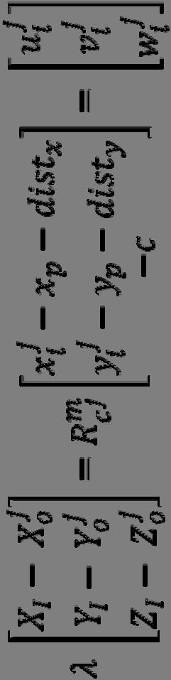
65 65 Intersection: Linear Model c dist y y dist x x R V c dist y y dist x x R V Z Z Y Y X X B y p r x p r r y p l x p l l o o o o o o r r r l l l l r l r l r ),, ( ),, ( These vectors are given w.r.t. the ground coordinate system.
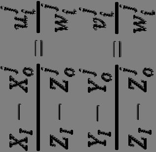
66 66 Intersection: Linear Model c dist y y dist x x R c dist y y dist x x R Z Z Y Y X X V B V y p r x p r y p l x p l o o o o o o r l r r r l l l l r l r l r ),, ( ),, ( Three equations in two unknowns (). They are linear equations.
67 67 Intersection: Linear Model c dist y y dist x x R Z Y X Z Y X y p l x p l o o o l l l l l l l ),, ( ˆ ˆ ˆ ˆ c dist y y dist x x R Z Y X Z Y X y p r x p r o o o r r r r r r r ),, ( ˆ ˆ ˆ ˆ, or,, weighted average of the above two estimates
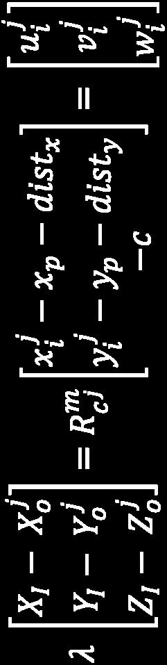

68 Intersection: Multi-Light Ray Intersection i: point index j: image index 68


69 Intersection: Multi-Light Ray Intersection i: point index j: image index n images 2n equations in 3 unknowns 69
70 Terrestrial Mobile Mapping Systems Operational Example 70
71 Mobile Mapping Systems: Introduction Definition Mobile Mapping Systems (MMS) can be defined as moving platforms upon which multiple sensors / measurement systems have been integrated to provide three-dimensional nearcontinuous positioning of both the platform s path in space and simultaneously collected geo-spatial data. Includes therefore Planes, trains, automobiles 71
72 Terrestrial MMS: Motivation Increasing need for digital land-related information, (GIS) Road network data is of special interest. Road network data can be collected via: Digitizing existing maps (inherit existing errors), or Site surveying Mobile Mapping Systems (MMS) are fast, accurate, economic, and current data collection devices. 72
73 Basic requirements: Mobile Mapping Systems Positioning capabilities GNSS and INS Knowledge about the surrounding environment Radar, Laser, and/or Optical camera(s) The involved operational example includes: GNSS receiver, Inertial Navigation System (INS), and Stereo-vision system. 73
74 GNSS/INS Component IMU b-frame r m b R m b ( t) ( t) 74
75 Stereo-Vision System r m c i R m c i ( t) i 1: n ( t) (nis thenumber of cameras) 75

76 Terrestrial MMS: Operational Example 76
77 Coordinate Systems y l Z V z l x l y r Y V z r x r Z G X V Y G X G Equivalent to the IMU body frame 77
78 Coordinate Systems (x l, y l, z l ) Image coordinate system for the left camera station (x r, y r, z r ) Image coordinate system for the right camera station (X V, Y V, Z V ) Van coordinate system: Origin at the GNSS antenna phase center Y V coincides with the driving direction Z V is pointing upward The van coordinate system is parallel to the IMU body frame coordinate system. (X G, Y G, Z G ) Ground coordinate system 78
79 System Calibration The interior orientation parameters of the used cameras The coordinates of the principal point, The focal length, and Distortion parameters The spatial and rotational offsets between the right and the left camera stations. X r Y r Z r r r r Those offsets can be determined through: Bundle adjustment using some tie points and distance measurements in the object space The spatial and rotational offsets between the left camera and the IMU body frame. 79
80 Relationship Between the Two Camera Stations y l x r z l x l z r y r The left camera coordinate system defines the model coordinate system. 80
81 Stereo Positioning: Model Coordinates y l y r z l x l z r x r 81
82 Model-to-Van Coordinate Transformation The spatial and rotational offsets between the left camera station and the van coordinate system X l V Y l V Z l V l V l V l V The components of the spatial and rotational offsets can be determined through a system calibration procedure. 82
83 Model-to-Van Coordinate Transformation Z V Y V X l V Z l V X V Y l V 83
84 Van-to-Ground Coordinate Transformation The spatial and rotational offsets between the van and ground coordinate systems X V G Y V G Z V G Azimuth Pitch Roll Those offsets are determined from the onboard GNSS/INS unit (GNSS/INS-integration process). 84
85 Van-to-Ground Coordinate Transformation Z G Y G X V G Z V G X G Y V G 85
86 Sample Calibration File (*.cop) Relationship between the two camera stations: IOPs for the left camera station: IOPs for the right camera station: Relationship between the left camera station and the van coordinate system:
87 Van Orientation Parameters (*.vop) The relationship between the van and ground coordinate systems X V G Y V G Z V G Azimuth Pitch Roll Spatial offset: Rotational offset (Azimuth, Pitch and Roll): Those offsets are computed after GNSS/INS-integration at the moment of exposure for a specific stereo-pair (stereo-pair # 587 in this case). 87
88 Time Synchronization t GNSS observation INS observation Moment of exposure 88
89 Terrestrial MMS: 3-D Positioning 89
90 Step 1: Stereo Measurement 90

 Red lines")
91 Step 1: Stereo Measurement Output: (x l, y l ) & (x r, y r ) Red lines epipolar lines 91
92 Step 2: Intersection (x l, y l ) a (x r, y r ) a (X M, Y M, Z M ) Object Point (A) 92
93 Epipolar Geometry O O Epipolar Line a a` Epipolar Plane A 93
94 Epipolar Geometry (Remarks) The epipolar plane can be defined once we have: The Relative Orientation Parameters (ROP) relating the two images of a stereo-pair, and Image coordinate measurements in either the left or right image. Conjugate points are located along conjugate epipolar lines. 94
95 Step 2: Intersection y l y r z l x l z r x r 95
96 Given: Step 2: Intersection Left and right image coordinates of a selected feature in one stereo-pair, The IOPs of the left and right cameras, and The spatial and rotational offsets between the left and right camera stations Output: (X M, Y M, Z M ) model coordinates of the selected feature relative to the left camera coordinate system 96
97 Step 3: Model-to-Global Coordinate Trans. Input: (X M, Y M, Z M ) model coordinates of the selected feature relative to the left camera coordinate system, The spatial and rotational offsets between the left camera station and the van coordinate systems, and The spatial and rotational offsets between the van and ground coordinate systems Output: (X G, Y G, Z G ) ground coordinates of the selected feature 97
98 98 Step 3-a: Model-to-Van Coordinate Trans. M M M l l l l l l V V V Z Y X R Z Y X Z Y X V V V V V V ),, ( V R l V r l (t) r l I (t) r V I
99 99 Step 3-b: Van-to-Ground Coordinate Trans. V V V V V V G G G Z Y X Roll Pitch Azimuth R Z Y X Z Y X G G G ),, ( (t) R m V r m (t) V (t) r V I m r I
100 Error Sources Measurement errors Interior Orientation Parameters (IOPs) Relative relationship between the two camera stations Offset between the left camera station and the van coordinate system GNSS/INS errors GNSS blockage - foliage, bridges Base stations Distance from cameras 100
101 Measurement Errors & Object Distance Z Z C Z B p x Z B c 101
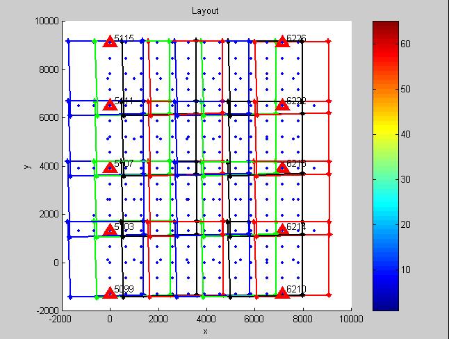
102 Drive along all roads Two GNSS base stations Field Procedure Quality control Datum, map projections, heights Check points Independent check of system accuracy 102
 2 : Derived from direct geodetic measurements (e.g., GNSS) 103")
103 Quality Control Points: Check Points (XYZ) 1 : Derived from the MMS (XYZ) 2 : Derived from direct geodetic measurements (e.g., GNSS) 103
104 Data Processing GNSS post-processing Integration of INS and GNSS Image storage - JPEG archives Camera calibration Output: XYZ coordinates of objects in the stereo-vision system field of view Additional attributes (e.g., feature type and some notes) 104
105 MMS Application: Traffic Signs Inventory sign type height above pavement offset from road edge coordinate locations size of sign 105
106 MMS Application: Asset Management Collecting inventories Database integration On-going maintenance 106
107 Direct Versus Indirect Geo-Referencing Accuracy Analysis 107
108 Overview Objectives Performance criterion and analysis environment Experimental results: Aerial Triangulation Integrated sensor orientation, and Indirect geo-referencing Intersection Intersection (direct geo-referencing) versus aerial triangulation Conclusions 108
109 Objective The main objective of this work is to investigate several issues associated with direct and indirect georeferencing: Accuracy Configuration requirements Sensitivity against problems in the IOPs Triangulation versus intersection We implemented synthetic/simulated data for the experiments to restrict the error analysis to the assumed error sources. 109
110 Performance Criterion The performance of different scenarios is evaluated through Root Mean Square Error (RMSE) analysis: Compares the adjusted ground coordinates from the triangulation or intersection procedures with the true values used for the simulation This criterion is very important since it addresses the quality of the reconstructed object space (the ultimate objective of photogrammetric mapping). 110
111 Analysis Environment Bundle adjustment software is used to conduct the experiments. This software can incorporate the following prior information: Stochastic ground coordinates of the control points, Stochastic IOPs, and Stochastic GNSS/INS-position/orientation at the perspective centers 111
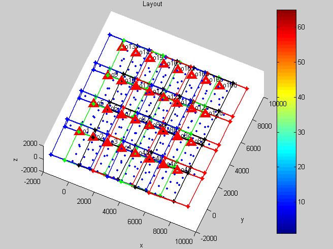
112 Test Data & Configurations 112
113 Configuration Flying height = m Focal length = 150mm Thirty-two images in four strips 60% over-lap (20 and 60)% side-lap Four/ten ground control points at the corners/edges of the block (±10cm) Image coordinate measurement accuracy (±5m) IOPs (±5m): 50 m Bias GNSS/INS-position information at the perspective centers (±10cm): 10cm Lever Arm Bias GNSS/INS-attitude information (±10sec): 0.05 Boresight Bias 113

114 Experiment I 114
115 Experiment II 115
116 Experiment III 116

117 Experiment IV 117
118 RMSE Results: No Biases ISO GCP-4 (I) GNSS/INS Pos. (II) GNSS/INS Pos./Attitude (II) GCP_10 (III) GCP_4 60%SL (IV) X (m) Y (m) Z (m)
119 Indirect Geo-Referencing Block coverage Control point The vertical accuracy within a block, which has control only at its corners, is worse at the center of the block. The vertical accuracy will deteriorate as the size of the block increases. Incorporating the GNSS or GNSS/INS observations at the exposure stations in the bundle adjustment procedure (ISO) would improve the vertical accuracy within the block. 119
120 Remarks Using GNSS/INS Pos. pc or GCPs almost yields equivalent horizontal accuracy. GNSS/INS Pos. observations at the perspective centers help in de-coupling and Y o, which significantly improves the vertical accuracy. Adding GNSS/INS attitude information at the perspective centers has a minor effect on improving the results (as far as the object space is concerned). 120
121 Experiment I (GCP-4) EOPs Variance-Correlation Matrix sec 2 ) sec 2 ) sec 2 ) X o (m 2 )Y o (m 2 )Z o (m 2 )
122 Experiment II (GNSS/INS Position) EOPs Variance-Correlation Matrix sec 2 ) sec 2 ) sec 2 ) X o (m 2 )Y o (m 2 )Z o (m 2 )
123 Experiment II (GNSS/INS Position/Attitude) EOPs Variance-Correlation Matrix sec 2 ) sec 2 ) sec 2 ) X o (m 2 )Y o (m 2 )Z o (m 2 )
124 Experiment III (GCP 10) EOPs Variance-Correlation Matrix sec 2 ) sec 2 ) sec 2 ) X o (m 2 )Y o (m 2 )Z o (m 2 )
125 Experiment IV (60% Side Lap) EOPs Variance-Correlation Matrix sec 2 ) sec 2 ) sec 2 ) X o (m 2 )Y o (m 2 )Z o (m 2 )
126 RMSE Results: IOPs Biases Bias in the IOPs (50m) x p, y p, & f Bias in f (50m) GCP-4 IOP (I) GNSS/INS Pos. IOP (II) GNSS/INS Pos. GCP-2 IOP (II) ISO GNSS/INS Pos./Attit. IOP (II) GNSS/INS Pos. f (II) X (m) Y (m) Z (m)
127 RMSE Results ISO GCP-10 (III) GCP-10 IOP (III) GNSS/INS Pos. (II) GNSS/INS Pos. IOP (II) X (m) Y (m) Z (m)
128 Experiment II (GNSS/INS) GNSS/INS-attitude information with 0.05º bias in the boresight angles Assumed to be accurate up to ±10sec RMSE Values (Check Point Analysis): X = 1.16 m Y = 1.54 m Z = 1.14 m 128
129 Aerial Triangulation / Intersection Bias GNSS/INS (POS.) AT (m) Intersection (m) No Bias IOPS Lever Arm Boresight
130 AT - Experiment II (GNSS/INS) EOPs Variance-Correlation Matrix sec 2 ) sec 2 ) sec 2 ) X o (m 2 )Y o (m 2 )Z o (m 2 )
131 AT - Experiment II (GNSS/INS) IOPs Variance-Correlation Matrix x p (mm 2 ) y p (mm 2 ) c (mm 2 ) 2.501e e e e e e e e e
132 Remarks In case of a bias in the IOPs, RMSE values obtained from GNSS/INS (position/attitude) AT and Intersection are almost the same. In contrast, GNSS/INS (position/attitude) AT significantly improves the point precision if either no bias, a bias in the lever arm, or bias in the boresight matrix is present. 132
133 Conclusions The main emphasis should be placed on the quality of the reconstructed object space rather than the quality of the derived EOPs from the onboard GNSS/INS unit. In the absence of systematic errors, integrated sensor orientation and indirect geo-referencing yield comparable results. Integrated sensor orientation leads to better results than intersection (direct geo-referencing). In the presence of systematic errors, indirect georeferencing produces better results than the integrated sensor orientation and direct geo-referencing. 133
134 Indirect geo-referencing: Conclusions IOPs + IOPs EOPs + EOPs EOPs + EOPs + IOPs + IOPs Correct Object Space Direct geo-referencing: (IOPs + IOPs) GNSS/INS EOPs EOPs + IOPs + IOPs Wrong Object Space 134
Chapter 1: Overview. Photogrammetry: Introduction & Applications Photogrammetric tools:
 Chapter 1: Overview Photogrammetry: Introduction & Applications Photogrammetric tools: Rotation matrices Photogrammetric point positioning Photogrammetric bundle adjustment This chapter will cover the
Chapters 1 7: Overview
 Chapters 1 7: Overview Chapter 1: Introduction Chapters 2 4: Data acquisition Chapters 5 7: Data manipulation Chapter 5: Vertical imagery Chapter 6: Image coordinate measurements and refinements Chapter
Exterior Orientation Parameters
 Exterior Orientation Parameters PERS 12/2001 pp 1321-1332 Karsten Jacobsen, Institute for Photogrammetry and GeoInformation, University of Hannover, Germany The georeference of any photogrammetric product
CE 59700: LASER SCANNING
 Digital Photogrammetry Research Group Lyles School of Civil Engineering Purdue University, USA Webpage: http://purdue.edu/ce/ Email: ahabib@purdue.edu CE 59700: LASER SCANNING 1 Contact Information Instructor:
Geometry of Aerial photogrammetry. Panu Srestasathiern, PhD. Researcher Geo-Informatics and Space Technology Development Agency (Public Organization)
") Geometry of Aerial photogrammetry Panu Srestasathiern, PhD. Researcher Geo-Informatics and Space Technology Development Agency (Public Organization) Image formation - Recap The geometry of imaging system
Geometry of Aerial photogrammetry Panu Srestasathiern, PhD. Researcher Geo-Informatics and Space Technology Development Agency (Public Organization) Image formation - Recap The geometry of imaging system
ifp Universität Stuttgart Performance of IGI AEROcontrol-IId GPS/Inertial System Final Report
 Universität Stuttgart Performance of IGI AEROcontrol-IId GPS/Inertial System Final Report Institute for Photogrammetry (ifp) University of Stuttgart ifp Geschwister-Scholl-Str. 24 D M. Cramer: Final report
Chapters 1-4: Summary
 Chapters 1-4: Summary So far, we have been investigating the image acquisition process. Chapter 1: General introduction Chapter 2: Radiation source and properties Chapter 3: Radiation interaction with
ADS40 Calibration & Verification Process. Udo Tempelmann*, Ludger Hinsken**, Utz Recke*
 ADS40 Calibration & Verification Process Udo Tempelmann*, Ludger Hinsken**, Utz Recke* *Leica Geosystems GIS & Mapping GmbH, Switzerland **Ludger Hinsken, Author of ORIMA, Konstanz, Germany Keywords: ADS40,
PERFORMANCE ANALYSIS OF FAST AT FOR CORRIDOR AERIAL MAPPING
 PERFORMANCE ANALYSIS OF FAST AT FOR CORRIDOR AERIAL MAPPING M. Blázquez, I. Colomina Institute of Geomatics, Av. Carl Friedrich Gauss 11, Parc Mediterrani de la Tecnologia, Castelldefels, Spain marta.blazquez@ideg.es
COMBINED BUNDLE BLOCK ADJUSTMENT VERSUS DIRECT SENSOR ORIENTATION ABSTRACT
 COMBINED BUNDLE BLOCK ADJUSTMENT VERSUS DIRECT SENSOR ORIENTATION Karsten Jacobsen Institute for Photogrammetry and Engineering Surveys University of Hannover Nienburger Str.1 D-30167 Hannover, Germany
The Applanix Approach to GPS/INS Integration
 Lithopoulos 53 The Applanix Approach to GPS/INS Integration ERIK LITHOPOULOS, Markham ABSTRACT The Position and Orientation System for Direct Georeferencing (POS/DG) is an off-the-shelf integrated GPS/inertial
Photogrammetry: DTM Extraction & Editing
 Photogrammetry: DTM Extraction & Editing Review of terms Vertical aerial photograph Perspective center Exposure station Fiducial marks Principle point Air base (Exposure Station) Digital Photogrammetry:
IMPACT OF CAMERA AND SYSTEM CALIBRATION ON PHOTOGRAMMETRIC RECONSTRUCTION USING MEDIUM FORMAT DIGITAL CAMERA
 IMPACT OF CAMERA AND SYSTEM CALIBRATION ON PHOTORAMMETRIC RECONSTRUCTION USIN MEDIUM FORMAT DIITAL CAMERA A. Habib a *, A. Kersting a, C. Kim a, J. Chow a a Department of eomatics Engineering, University
APPLICATION AND ACCURACY EVALUATION OF LEICA ADS40 FOR LARGE SCALE MAPPING
 APPLICATION AND ACCURACY EVALUATION OF LEICA ADS40 FOR LARGE SCALE MAPPING WenYuan Hu a, GengYin Yang b, Hui Yuan c,* a, b ShanXi Provincial Survey and Mapping Bureau, China - sxgcchy@public.ty.sx.cn c
ACCURACY ANALYSIS FOR NEW CLOSE-RANGE PHOTOGRAMMETRIC SYSTEMS
 ACCURACY ANALYSIS FOR NEW CLOSE-RANGE PHOTOGRAMMETRIC SYSTEMS Dr. Mahmoud El-Nokrashy O. ALI Prof. of Photogrammetry, Civil Eng. Al Azhar University, Cairo, Egypt m_ali@starnet.com.eg Dr. Mohamed Ashraf
Accuracy Assessment of POS AVX 210 integrated with the Phase One ixu150
 White Paper 3/17/2016 Accuracy Assessment of POS AVX 210 integrated with the Phase One ixu150 Omer Mian, Joe Hutton, Greg Lipa, James Lutes, Damir Gumerov, Srdjan Sobol Applanix, William Chan - GeoPixel
THE INTERIOR AND EXTERIOR CALIBRATION FOR ULTRACAM D
 THE INTERIOR AND EXTERIOR CALIBRATION FOR ULTRACAM D K. S. Qtaishat, M. J. Smith, D. W. G. Park Civil and Environment Engineering Department, Mu ta, University, Mu ta, Karak, Jordan, 61710 khaldoun_q@hotamil.com
LiDAR & Orthophoto Data Report
 LiDAR & Orthophoto Data Report Tofino Flood Plain Mapping Data collected and prepared for: District of Tofino, BC 121 3 rd Street Tofino, BC V0R 2Z0 Eagle Mapping Ltd. #201 2071 Kingsway Ave Port Coquitlam,
TERRESTRIAL AND NUMERICAL PHOTOGRAMMETRY 1. MID -TERM EXAM Question 4
 TERRESTRIAL AND NUMERICAL PHOTOGRAMMETRY 1. MID -TERM EXAM Question 4 23 November 2001 Two-camera stations are located at the ends of a base, which are 191.46m long, measured horizontally. Photographs
Photogrammetry: DTM Extraction & Editing
 Photogrammetry: DTM Extraction & Editing How can one determine the x, y, and z of a location? Approaches to DTM Extraction Ground surveying Digitized topographic maps Traditional photogrammetry Hardcopy
Training i Course Remote Sensing Basic Theory & Image Processing Methods September 2011
 Training i Course Remote Sensing Basic Theory & Image Processing Methods 19 23 September 2011 Geometric Operations Michiel Damen (September 2011) damen@itc.nl ITC FACULTY OF GEO-INFORMATION SCIENCE AND
LIDAR SYSTEM SELF-CALIBRATION USING PLANAR PATCHES FROM PHOTOGRAMMETRIC DATA
 LIDAR SSTEM SELF-CALIBRATION USING PLANAR PATCHES FROM PHOTOGRAMMETRIC DATA Ayman F. Habib a, *, Ki In Bang a, Sung-Woong Shin b, Edson Mitishita c a Department of Geomatics Engineering, University of
AUTOMATIC IMAGE ORIENTATION BY USING GIS DATA
 AUTOMATIC IMAGE ORIENTATION BY USING GIS DATA Jeffrey J. SHAN Geomatics Engineering, School of Civil Engineering Purdue University IN 47907-1284, West Lafayette, U.S.A. jshan@ecn.purdue.edu Working Group
AN INTEGRATED SENSOR ORIENTATION SYSTEM FOR AIRBORNE PHOTOGRAMMETRIC APPLICATIONS
 AN INTEGRATED SENSOR ORIENTATION SYSTEM FOR AIRBORNE PHOTOGRAMMETRIC APPLICATIONS M. J. Smith a, *, N. Kokkas a, D.W.G. Park b a Faculty of Engineering, The University of Nottingham, Innovation Park, Triumph
TRAINING MATERIAL HOW TO OPTIMIZE ACCURACY WITH CORRELATOR3D
 TRAINING MATERIAL WITH CORRELATOR3D Page2 Contents 1. UNDERSTANDING INPUT DATA REQUIREMENTS... 4 1.1 What is Aerial Triangulation?... 4 1.2 Recommended Flight Configuration... 4 1.3 Data Requirements for
POSITIONING A PIXEL IN A COORDINATE SYSTEM
 GEOREFERENCING AND GEOCODING EARTH OBSERVATION IMAGES GABRIEL PARODI STUDY MATERIAL: PRINCIPLES OF REMOTE SENSING AN INTRODUCTORY TEXTBOOK CHAPTER 6 POSITIONING A PIXEL IN A COORDINATE SYSTEM The essential
Aalborg Universitet. Published in: Accuracy Publication date: Document Version Early version, also known as pre-print
 Aalborg Universitet A method for checking the planimetric accuracy of Digital Elevation Models derived by Airborne Laser Scanning Høhle, Joachim; Øster Pedersen, Christian Published in: Accuracy 2010 Publication
Chapters 1 5. Photogrammetry: Definition, introduction, and applications. Electro-magnetic radiation Optics Film development and digital cameras
 Chapters 1 5 Chapter 1: Photogrammetry: Definition, introduction, and applications Chapters 2 4: Electro-magnetic radiation Optics Film development and digital cameras Chapter 5: Vertical imagery: Definitions,
GUIDELINES FOR THE IN SITU GEOMETRIC CALIBRATION OF THE AERIAL CAMERA SYSTEM
 GUIDELINES FOR THE IN SITU GEOMETRIC CALIBRATION OF THE AERIAL CAMERA SYSTEM These guidelines have been developed by the Primary Data Acquisition Division and the Camera Calibration Committee, and have
SimActive and PhaseOne Workflow case study. By François Riendeau and Dr. Yuri Raizman Revision 1.0
 SimActive and PhaseOne Workflow case study By François Riendeau and Dr. Yuri Raizman Revision 1.0 Contents 1. Introduction... 2 1.1. Simactive... 2 1.2. PhaseOne Industrial... 2 2. Testing Procedure...
GI-Eye II GPS/Inertial System For Target Geo-Location and Image Geo-Referencing
 GI-Eye II GPS/Inertial System For Target Geo-Location and Image Geo-Referencing David Boid, Alison Brown, Ph. D., Mark Nylund, Dan Sullivan NAVSYS Corporation 14960 Woodcarver Road, Colorado Springs, CO
GEOREFERENCING EXPERIMENTS WITH UAS IMAGERY
 GEOREFERENCING EXPERIMENTS WITH UAS IMAGERY G. Jóźków *, C. Toth Satellite Positioning and Inertial Navigation (SPIN) Laboratory The Ohio State University, Department of Civil, Environmental and Geodetic
Iowa Department of Transportation Office of Design. Photogrammetric Mapping Specifications
 Iowa Department of Transportation Office of Design Photogrammetric Mapping Specifications March 2015 1 Purpose of Manual These Specifications for Photogrammetric Mapping define the standards and general
THE DIRECT GEOREFERENCING APPLICATION AND PERFORMANCE ANALYSIS OF UAV HELICOPTER IN GCP-FREE AREA
 THE DIRECT GEOREFERENCING APPLICATION AND PERFORMANCE ANALYSIS OF UAV HELICOPTER IN GCP-FREE AREA C.F. Lo a, M.L. Tsai b, *, K.W. Chiang c, C.H. Chu d, G.J. Tsai e, C.K. Cheng f, N. El-Sheimy g, H. Ayman
IN-FLIGHT GEOMETRIC CALIBRATION OF FORE AND AFT CAMERAS OF CARTOSAT- 1
 IN-FLIGHT GEOMETRIC CALIBRATION OF FORE AND AFT CAMERAS OF CARTOSAT- 1 By P.V. RADHADEVI* (adrin_radhadevi@yahoo.co.in) Advanced Data Processing Research Institute (ADRIN), Department of Space, Government
PREPARATIONS FOR THE ON-ORBIT GEOMETRIC CALIBRATION OF THE ORBVIEW 3 AND 4 SATELLITES
 PREPARATIONS FOR THE ON-ORBIT GEOMETRIC CALIBRATION OF THE ORBVIEW 3 AND 4 SATELLITES David Mulawa, Ph.D. ORBIMAGE mulawa.david@orbimage.com KEY WORDS: Geometric, Camera, Calibration, and Satellite ABSTRACT
Photogrammetry: A Modern Tool for Crash Scene Mapping
 Photogrammetry: A Modern Tool for Crash Scene Mapping Background A police accident investigator (AI) has many tasks when arriving at a crash scene. The officer s highest priority is public safety; the
a Geo-Odyssey of UAS LiDAR Mapping Henno Morkel UAS Segment Specialist DroneCon 17 May 2018
 a Geo-Odyssey of UAS LiDAR Mapping Henno Morkel UAS Segment Specialist DroneCon 17 May 2018 Abbreviations UAS Unmanned Aerial Systems LiDAR Light Detection and Ranging UAV Unmanned Aerial Vehicle RTK Real-time
REMOTE SENSING LiDAR & PHOTOGRAMMETRY 19 May 2017
 REMOTE SENSING LiDAR & PHOTOGRAMMETRY 19 May 2017 SERVICES Visual Inspections Digital Terrain Models Aerial Imagery Volume Computations Thermal Inspections Photo maps Aerial Video Training & Consultancy
DETERMINATION OF IMAGE ORIENTATION SUPPORTED BY IMU AND GPS
 DETERMINATION OF IMAGE ORIENTATION SUPPORTED BY IMU AND GPS Karsten Jacobsen University of Hannover Institute for Photogrammetry and Engineering Surveys Nienburger Str. 1 D-30167 Hannover Jacobsen@ipi.uni-hannover.de
DIRECT GEOREFERENCING USING GPS/INERTIAL EXTERIOR ORIENTATIONS FOR PHOTOGRAMMETRIC APPLICATIONS
 DIRECT GEOREFERENCING USING GPS/INERTIAL EXTERIOR ORIENTATIONS FOR PHOTOGRAMMETRIC APPLICATIONS Michael Cramer, Dirk Stallmann and Norbert Haala Institute for Photogrammetry (ifp) University of Stuttgart,
STUDY OF THE INTEGRATION OF LIDAR AND PHOTOGRAMMETRIC DATASETS BY IN SITU CAMERA CALIBRATION AND INTEGRATED SENSOR ORIENTATION
 STUDY OF THE INTEGRATION OF LIDAR AND PHOTOGRAMMETRIC DATASETS BY IN SITU CAMERA CALIBRATION AND INTEGRATED SENSOR ORIENTATION Mitishita, E *., Costa, F., Martins, M. Geodetic Sciences Graduate Program
DISSERTATION. The Degree Doctor of Philosophy in the Graduate. School of The Ohio State University. Nora Csanyi May, M.S. *****
 A RIGOROUS APPROACH TO COMPREHENSIVE PERFORMANCE ANALYSIS OF STATE-OF-THE-ART AIRBORNE MOBILE MAPPING SYSTEMS DISSERTATION Presented in Partial Fulfillment of the Requirements for The Degree Doctor of
Chapters 1 5. Photogrammetry: Definition, introduction, and applications. Electro-magnetic radiation Optics Film development and digital cameras
 Chapters 1 5 Chapter 1: Photogrammetry: Definition, introduction, and applications Chapters 2 4: Electro-magnetic radiation Optics Film development and digital cameras Chapter 5: Vertical imagery: Definitions,
Camera Calibration for a Robust Omni-directional Photogrammetry System
 Camera Calibration for a Robust Omni-directional Photogrammetry System Fuad Khan 1, Michael Chapman 2, Jonathan Li 3 1 Immersive Media Corporation Calgary, Alberta, Canada 2 Ryerson University Toronto,
ON THE ACCURAY AND PERFORMANCE OF THE GEOMÒBIL SYSTEM
 ON THE ACCURAY AND PERFORMANCE OF THE GEOMÒBIL SYSTEM R. Alamús, A.Baron, E.Bosch, J.Casacuberta, J.Miranda, M.Pla, S.Sànchez, A.Serra, J.Talaya Institut Cartogràfic de Catalunya (ICC), Parc de Montjuïc,
CALIBRATION ASPECTS IN DIRECT GEOREFERENCING OF FRAME IMAGERY
 CALIBRATION ASPECTS IN DIRECT GEOREFERENCING OF FRAME IMAGERY Karsten Jacobsen University of Hannover Institute for Photogrammetry and GeoInformation Nienburger Str. 1 D-30167 Hannover, Germany jacobsen@ipi.uni-hannover.de
Stability Analysis for a Multi-Camera Photogrammetric System
 Sensors 2014, 14, 15084-15112; doi:10.3390/s140815084 Article OPEN ACCESS sensors ISSN 1424-8220 www.mdpi.com/journal/sensors Stability Analysis for a Multi-Camera Photogrammetric System Ayman Habib 1,
FAST REGISTRATION OF TERRESTRIAL LIDAR POINT CLOUD AND SEQUENCE IMAGES
 FAST REGISTRATION OF TERRESTRIAL LIDAR POINT CLOUD AND SEQUENCE IMAGES Jie Shao a, Wuming Zhang a, Yaqiao Zhu b, Aojie Shen a a State Key Laboratory of Remote Sensing Science, Institute of Remote Sensing
Airborne Direct Georeferencing of Frame Imagery: An Error Budget
 Airborne Direct Georeferencing of Frame Imagery: An Error Budget Mohamed M.R. Mostafa, Joseph Hutton, and Erik Lithopoulos APPLANIX Corporation 85 Leek Cr., Richmond Hill Ontario, Canada L4B 3B3 Phone:
Sensor Integration and Image Georeferencing for Airborne 3D Mapping Applications
 Sensor Integration and Image Georeferencing for Airborne 3D Mapping Applications By Sameh Nassar and Naser El-Sheimy University of Calgary, Canada Contents Background INS/GPS Integration & Direct Georeferencing
Lecture 5. Relief displacement. Parallax. Monoscopic and stereoscopic height measurement. Photo Project. Soft-copy Photogrammetry.
 NRMT 2270, Photogrammetry/Remote Sensing Lecture 5 Relief displacement. Parallax. Monoscopic and stereoscopic height measurement. Photo Project. Soft-copy Photogrammetry. Tomislav Sapic GIS Technologist
ArcMap as a quality assurance tool in Photogrammetry Ron Frederiks. Abstract
 ArcMap as a quality assurance tool in Photogrammetry Ron Frederiks Abstract This paper presents the use of ArcMap, 3-D Analyst, Spatial Analyst and Ianko s ETGeoWizards to perform quality assurance of
BUNDLE BLOCK ADJUSTMENT WITH HIGH RESOLUTION ULTRACAMD IMAGES
 BUNDLE BLOCK ADJUSTMENT WITH HIGH RESOLUTION ULTRACAMD IMAGES I. Baz*, G. Buyuksalih*, K. Jacobsen** * BIMTAS, Tophanelioglu Cad. ISKI Hizmet Binasi No:62 K.3-4 34460 Altunizade-Istanbul, Turkey gb@bimtas.com.tr
PHOTOGRAMMETRIC SOLUTIONS OF NON-STANDARD PHOTOGRAMMETRIC BLOCKS INTRODUCTION
 PHOTOGRAMMETRIC SOLUTIONS OF NON-STANDARD PHOTOGRAMMETRIC BLOCKS Dor Yalon Co-Founder & CTO Icaros, Inc. ABSTRACT The use of small and medium format sensors for traditional photogrammetry presents a number
An Overview of Applanix.
 An Overview of Applanix The Company The Industry Leader in Developing Aided Inertial Technology Founded on Canadian Aerospace and Defense Industry Expertise Providing Precise Position and Orientation Systems
Introduction Photogrammetry Photos light Gramma drawing Metron measure Basic Definition The art and science of obtaining reliable measurements by mean
 Photogrammetry Review Neil King King and Associates Testing is an art Introduction Read the question Re-Read Read The question What is being asked Answer what is being asked Be in the know Exercise the
Geometric Rectification of Remote Sensing Images
 Geometric Rectification of Remote Sensing Images Airborne TerrestriaL Applications Sensor (ATLAS) Nine flight paths were recorded over the city of Providence. 1 True color ATLAS image (bands 4, 2, 1 in
GEO-REFERENCING CASI IMAGERY USING DIRECT MEASUREMENT OF POSITION AND ATTITUDE
 GEO-REFERENCING CASI IMAGERY USING DIRECT MEASUREMENT OF POSITION AND ATTITUDE Rakesh K. SHUKLA *, Martin J. SMITH Institute of Engineering Surveying and Space Geodesy The University of Nottingham University
INVESTIGATION OF 1:1,000 SCALE MAP GENERATION BY STEREO PLOTTING USING UAV IMAGES
 INVESTIGATION OF 1:1,000 SCALE MAP GENERATION BY STEREO PLOTTING USING UAV IMAGES S. Rhee a, T. Kim b * a 3DLabs Co. Ltd., 100 Inharo, Namgu, Incheon, Korea ahmkun@3dlabs.co.kr b Dept. of Geoinformatic
PHOTOGRAMMETRIC PROCESSING OF LOW ALTITUDE IMAGE SEQUENCES BY UNMANNED AIRSHIP
 PHOTOGRAMMETRIC PROCESSING OF LOW ALTITUDE IMAGE SEQUENCES BY UNMANNED AIRSHIP Yongjun Zhang School of Remote Sensing and Information Engineering, Wuhan University, Wuhan, Hubei, 430079, P.R. China - zhangyj@whu.edu.cn
Extracting Elevation from Air Photos
 Extracting Elevation from Air Photos TUTORIAL A digital elevation model (DEM) is a digital raster surface representing the elevations of a terrain for all spatial ground positions in the image. Traditionally
Multi-Image Geo Location and 3D Feature Extraction from Stereo. Gene Rose
 Multi-Image Geo Location and 3D Feature Extraction from Stereo Gene Rose Introduction In RemoteView, both basic and advanced Photogrammetric processes are available. The white paper titled Basic Photogrammetry
Direct Sensor Orientation of a Land-Based Mobile Mapping System
 Sensors 2011, 11, 7243-7261; doi:10.3390/s110707243 OPEN ACCESS sensors ISSN 1424-8220 www.mdpi.com/journal/sensors Article Direct Sensor Orientation of a Land-Based Mobile Mapping System Jiann-Yeou Rau
The Development of an UAV Borne Direct Georeferenced Photogrammetric Platform for Ground Control Point Free Applications
 Sensors 2012, 12, 9161-9180; doi:10.3390/s120709161 Article OPEN ACCESS sensors ISSN 1424-8220 www.mdpi.com/journal/sensors The Development of an UAV Borne Direct Georeferenced Photogrammetric Platform
Characterizing Strategies of Fixing Full Scale Models in Construction Photogrammetric Surveying. Ryan Hough and Fei Dai
 697 Characterizing Strategies of Fixing Full Scale Models in Construction Photogrammetric Surveying Ryan Hough and Fei Dai West Virginia University, Department of Civil and Environmental Engineering, P.O.
Chapters 1 7: Overview
 Chapters 1 7: Overview Photogrammetric mapping: introduction, applications, and tools GNSS/INS-assisted photogrammetric and LiDAR mapping LiDAR mapping: principles, applications, mathematical model, and
MAPPING WITHOUT GROUND CONTROL POINTS: DOES IT WORK?
 MAPPING WITHOUT GROUND CONTROL POINTS: DOES IT WORK? BACKGROUND The economic advantages of Structure from Motion (SfM) mapping without any ground control points have motivated us to investigate an approach
EPIPOLAR IMAGES FOR CLOSE RANGE APPLICATIONS
 EPIPOLAR IMAGES FOR CLOSE RANGE APPLICATIONS Vassilios TSIOUKAS, Efstratios STYLIANIDIS, Petros PATIAS The Aristotle University of Thessaloniki, Department of Cadastre Photogrammetry and Cartography Univ.
Analysis of Different Reference Plane Setups for the Calibration of a Mobile Laser Scanning System
 Analysis of Different Reference Plane Setups for the Calibration of a Mobile Laser Scanning System 18. Internationaler Ingenieurvermessungskurs Graz, Austria, 25-29 th April 2017 Erik Heinz, Christian
OLC Wasco County: Delivery One.
 OLC Wasco County: Delivery One www.quantumspatial.com January 2, 2014 Trimble R7 Receiver set up over GPS monument WASCO_02. Data collected for: Oregon Department of Geology and Mineral Industries 800
ENY-C2005 Geoinformation in Environmental Modeling Lecture 4b: Laser scanning
 1 ENY-C2005 Geoinformation in Environmental Modeling Lecture 4b: Laser scanning Petri Rönnholm Aalto University 2 Learning objectives To recognize applications of laser scanning To understand principles
Assessing the Performance of Different Direct-Georeferencing with Large Format Digital Cameras
 Assessing the Performance of Different Direct-Georeferencing with Large Format Digital Cameras Civil and Environment Engineering Department, Mu ta University, Mu ta, Al-Karak, Jordan, 61710. E.mail: khaldoun_q@hotamil.com
STARTING WITH DRONES. Data Collection and Remote Sensing with UAVs, etc. Dr. Bill Hazelton LS
 STARTING WITH DRONES Data Collection and Remote Sensing with UAVs, etc. Dr. Bill Hazelton LS What this Talk is About UAV-based data acquisition: What you need to get involved Processes in getting spatial
WADDENZEE SPRING SURVEY
 Report Lidar Survey WADDENZEE SPRING SURVEY 2016 Datum: 6th of June 2016 Client: Nederlandse Aardolie Maatschappij : Author: W. Velthoven Reviewer: F. de Boeck Project number: N605 Version: v1 page 1 van
LIDAR MAPPING FACT SHEET
 1. LIDAR THEORY What is lidar? Lidar is an acronym for light detection and ranging. In the mapping industry, this term is used to describe an airborne laser profiling system that produces location and
Airborne Laser Survey Systems: Technology and Applications
 Abstract Airborne Laser Survey Systems: Technology and Applications Guangping HE Lambda Tech International, Inc. 2323B Blue Mound RD., Waukesha, WI-53186, USA Email: he@lambdatech.com As mapping products
Precise Kinematic GPS Processing and Rigorous Modeling of GPS in a Photogrammetric Block Adjustment
 Precise Kinematic GPS Processing and Rigorous Modeling of GPS in a Photogrammetric Block Adjustment Martin Schmitz, Gerhard Wübbena, Andreas Bagge Geo++ GmbH D-30827 Garbsen, Germany www.geopp.de Content
Trimble VISION Positions from Pictures
 Trimble VISION Positions from Pictures This session will cover What Is Trimble VISION? Trimble VISION Portfolio What Do you Need? How Does It Work & How Accurate Is It? Applications Resources Trimble VISION
ICC experiences on Inertial / GPS sensor orientation. A. Baron, W.Kornus, J.Talaya Institut Cartogràfic de Catalunya, ICC
 ICC experiences on Inertial / GPS sensor orientation A. Baron, W.Kornus, J.Talaya Institut Cartogràfic de Catalunya, ICC Keywords: GPS/INS orientation, robustness Abstract In the last few years the photogrammetric
Journal Online Jaringan COT POLIPD (JOJAPS) Accuracy Assessment of Height Coordinate Using Unmanned Aerial Vehicle Images Based On Leveling Height
 Accuracy Assessment of Height Coordinate Using Unmanned Aerial Vehicle Images Based On Leveling Height") JOJAPS eissn 2504-8457 Abstract Journal Online Jaringan COT POLIPD (JOJAPS) Accuracy Assessment of Height Coordinate Using Unmanned Aerial Vehicle Images Based On Leveling Height Syamsul Anuar Bin Abu
JOJAPS eissn 2504-8457 Abstract Journal Online Jaringan COT POLIPD (JOJAPS) Accuracy Assessment of Height Coordinate Using Unmanned Aerial Vehicle Images Based On Leveling Height Syamsul Anuar Bin Abu
Trimble Engineering & Construction Group, 5475 Kellenburger Road, Dayton, OH , USA
 Trimble VISION Ken Joyce Martin Koehler Michael Vogel Trimble Engineering and Construction Group Westminster, Colorado, USA April 2012 Trimble Engineering & Construction Group, 5475 Kellenburger Road,
COORDINATE TRANSFORMATION. Lecture 6
 COORDINATE TRANSFORMATION Lecture 6 SGU 1053 SURVEY COMPUTATION 1 Introduction Geomatic professional are mostly confronted in their work with transformations from one two/three-dimensional coordinate system
Third Rock from the Sun
 Geodesy 101 AHD LiDAR Best Practice The Mystery of LiDAR Best Practice Glenn Jones SSSi GIS in the Coastal Environment Batemans Bay November 9, 2010 Light Detection and Ranging (LiDAR) Basic principles
Terrestrial GPS setup Fundamentals of Airborne LiDAR Systems, Collection and Calibration. JAMIE YOUNG Senior Manager LiDAR Solutions
 Terrestrial GPS setup Fundamentals of Airborne LiDAR Systems, Collection and Calibration JAMIE YOUNG Senior Manager LiDAR Solutions Topics Terrestrial GPS reference Planning and Collection Considerations
Advanced Vision Guided Robotics. David Bruce Engineering Manager FANUC America Corporation
 Advanced Vision Guided Robotics David Bruce Engineering Manager FANUC America Corporation Traditional Vision vs. Vision based Robot Guidance Traditional Machine Vision Determine if a product passes or
PRECISION ANALYSIS OF VISUAL ODOMETRY BASED ON DISPARITY CHANGING
 PRECISION ANALYSIS OF VISUAL ODOMETRY BASED ON DISPARITY CHANGING C. Y. Fu a, J. R. Tsay a a Dept. of Geomatics, National Cheng Kung University, Tainan, Taiwan - (P66044099, tsayjr)@ncku.edu.tw Commission
LUMS Mine Detector Project
 LUMS Mine Detector Project Using visual information to control a robot (Hutchinson et al. 1996). Vision may or may not be used in the feedback loop. Visual (image based) features such as points, lines
Absolute Horizontal Accuracies of Pictometry s Individual Orthogonal Frame Imagery
 A Pictometry International, Corp White Paper Absolute Horizontal Accuracies of Pictometry s Individual Orthogonal Frame Imagery Michael J. Zoltek VP, Surveying & Mapping Pictometry International, Corp
Automating Data Alignment from Multiple Collects Author: David Janssen Optech Incorporated,Senior Technical Engineer
 Automating Data Alignment from Multiple Collects Author: David Janssen Optech Incorporated,Senior Technical Engineer Stand in Presenter: David Collison Optech Incorporated, Regional Sales Manager Introduction
GPS SUPPORTED AERIAL TRIANGULATION USING UNTARGETED GROUND CONTROL
 GPS SUPPORTED AERIAL TRIANGULATION USING UNTARGETED GROUND CONTROL Mirjam Bilker, Eija Honkavaara, Juha Jaakkola Finnish Geodetic Institute Geodeetinrinne 2 FIN-02430 Masala Finland Mirjam.Bilker@fgi.fi,
Development of a Test Field for the Calibration and Evaluation of Kinematic Multi Sensor Systems
 Development of a Test Field for the Calibration and Evaluation of Kinematic Multi Sensor Systems DGK-Doktorandenseminar Graz, Austria, 26 th April 2017 Erik Heinz Institute of Geodesy and Geoinformation
PART A Three-Dimensional Measurement with iwitness
 PART A Three-Dimensional Measurement with iwitness A1. The Basic Process The iwitness software system enables a user to convert two-dimensional (2D) coordinate (x,y) information of feature points on an
MONO-IMAGE INTERSECTION FOR ORTHOIMAGE REVISION
 MONO-IMAGE INTERSECTION FOR ORTHOIMAGE REVISION Mohamed Ibrahim Zahran Associate Professor of Surveying and Photogrammetry Faculty of Engineering at Shoubra, Benha University ABSTRACT This research addresses
Digital Photogrammetric System. Version 5.3 USER GUIDE. Processing of UAV data
 Digital Photogrammetric System Version 5.3 USER GUIDE Table of Contents 1. Workflow of UAV data processing in the system... 3 2. Create project... 3 3. Block forming... 5 4. Interior orientation... 6 5.
CO-REGISTRATION AIRBORNE LIDAR POINT CLOUD DATA AND SYNCHRONOUS DIGITAL IMAGE REGISTRATION BASED ON COMBINED ADJUSTMENT
 The International Archives of the Photogrammetry, Remote ensing and patial Information ciences, Volume XLI-B1, 2016 XXIII IPR Congress, 12 19 July 2016, Prague, Czech Republic CO-REGITRATION AIRBORNE LIDAR
Terrain Integrity Monitoring Studies using Kalman Filter for SVS
 Terrain Integrity Monitoring Studies using Kalman Filter for SVS Srikanth K P, Kamali C, Abhay Pashilkar FMCD, CSIR-National Aerospace Laboratories, Bangalore, India ABSTRACT: An important component of
COMPARATIVE ANALYSIS OF ALTERNATIVE IN-DOOR CALIBRATION TECHNIQUES FOR OFF-THE-SHELF DIGITAL CAMERAS INTRODUCTION
 COMPARATIVE ANALYSIS OF ALTERNATIVE IN-DOOR CALIBRATION TECHNIQUES FOR OFF-THE-SHELF DIGITAL CAMERAS Ivan Detchev, Axel Ebeling, Ayman Habib Department of Geomatics Engineering, University of Calgary,
APPLANIX DIRECT GEOREFERENCING FOR AIRBORNE MAPPING. and FLIGHT MANAGEMENT SYSTEMS. The Better Way to Reduce the Cost of Airborne Mapping
 APPLANIX DIRECT GEOREFERENCING and FLIGHT MANAGEMENT SYSTEMS FOR AIRBORNE MAPPING The Better Way to Reduce the Cost of Airborne Mapping capture everything. precisely. Applanix Direct Georeferencing and
AIRBORNE KINEMATIC GPS POSITIONING FOR PHOTOGRAMMETRY THE DETERMINATION OF THE CAMERA EXPOSURE STATION
 AIRBORNE KINEMATIC GPS POSITIONING FOR PHOTOGRAMMETRY THE DETERMINATION OF THE CAMERA EXPOSURE STATION Lewis A. Lapine, Ph.D. Chief, National Geodetic Survey Silver Spring, MD 20910 ABSTRACT Kinematic