On Plane-Based Camera Calibration: A General Algorithm, Singularities, Applications
|
|
|
- Amberlynn Holt
- 5 years ago
- Views:
Transcription
1 ACCEPTED FOR CVPR 99. VERSION OF NOVEMBER 18, On Plane-Based Camera Calibration: A General Algorithm, Singularities, Applications Peter F. Sturm and Stephen J. Maybank Computational Vision Group, Department of Computer Science The University of Reading Whiteknights, PO Box 225 Reading, RG6 6AY, United Kingdom {P.F.Sturm, S.J.Maybank}@reading.ac.uk Abstract We present a general algorithm for plane-based calibration that can deal with arbitrary numbers of views and calibration planes. The algorithm can simultaneously calibrate different views from a camera with variable intrinsic parameters and it is easy to incorporate known values of intrinsic parameters. For some minimal cases, we describe all singularities, naming the parameters that can not be estimated. Experimental results of our method are shown that exhibit the singularities while revealing good performance in non-singular conditions. Several applications of plane-based 3D geometry inference are discussed as well. 1 Introduction The motivations for considering planes for calibrating cameras are mainly twofold. First, concerning calibration in its own right, planar calibration patterns are cheap and easy to produce, a laser printer output for example is absolutely sufficient for applications where highest accuracy is not demanded. Second, planar surface patches are probably the most important twodimensional features : they abound, at least in man-made environments, and if their metric structure is known, they carry already enough information to determine a camera s pose up to only two solutions in general [3]. Planes are increasingly used for interactive modeling or measuring purposes [1, 9, 10]. The possibility of calibrating cameras from views of planar objects is well known [6, 11, 13]. Existing work however, restricts in most cases to the consideration of a single or only two planes (an exception is [7], but no details on the algorithm are provided) and cameras with constant calibration. In addition, the study of singular cases is usually neglected (besides in [11] for the simplest case, calibration of the aspect ratio from one view of a plane), despite their presence in common configurations. It is even possible for cameras to self-calibrate from views of planar scenes with unknown metric structure [12], however several views are needed (Triggs recommends up to 9 or 10 views of the same plane for reliable results) and the risk of singularities should be greater compared to calibration from planes with known metric structure. In this paper, we propose a general algorithm for calibrating a camera with possibly variable intrinsic parameters and position, that copes well with an arbitrary number of calibration planes (with known metric structure) and camera views. Calibration is essentially done in two steps. First, the 2D-to-2D projections of planar calibration objects onto the image plane(s) are computed. Each of these projections contributes to a system of homogeneous linear equations in the intrinsic parameters, which are hence easily determined. Calibration can thus be achieved using only linear operations (solving linear equations), but can of course be enhanced by subsequent non linear optimization. The paper is organised as follows: in 2, we describe the camera model used and the representation of projections of planar objects. In 3, we introduce the principle of plane-based calibration. A general algorithm is proposed in 4. Singularities are revealed in 5. Experimental results are presented in 6, and some applications described in 7. 2 Background Camera Model. We use perspective projection to model cameras. A projection may be represented by a 3 4 projection matrix P that maps points of 3-space to points in 2-space: q PQ. Here, means equality up to a non zero scale factor, which accounts for the use of homogeneous coordinates. The projection matrix incorporates nicely the so-called extrinsic and intrinsic camera parameters; it may be decomposed as: P KR( I 3 t), (1) where I 3 is the 3 3 identity matrix, R a 3 3 orthogonal matrix representing the camera s orientation, t a 3-vector representing its position, and K the 3 3 calibration matrix: 1
2 K = τf s u 0 0 f v In general, we distinguish 5 intrinsic parameters for the perspective projection model: the (effective) focal length f, the aspect ratio τ, the principal point (u 0, v 0 ) and the skew factor s accounting for non rectangular pixels. The skew factor is usually very close to 0, so we ignore it in the following. Calibration and Absolute Conic. Our aim here is to calibrate a camera, i.e. to determine its intrinsic parameters or its calibration matrix K (subsequent pose estimation is relatively straightforward). Instead of directly determining K, we will try to compute the symmetric matrix KK T or its inverse, from which the calibration matrix can be computed uniquely using Cholesky decomposition. As will be seen, this approach leads to simple and, in particular, linear calibration equations. Furthermore, the analysis of singularities of the calibration problem is greatly simplified: the matrix ω (KK T ) 1 = K T K 1 represents the image of the Absolute Conic whose link to calibration and metric scene reconstruction is exposed for example in [2]. This geometrical view helps us with the derivation of singular configurations (cf. 5). Planes, Homographies and Calibration. In this paper, we consider the use of one or several planar objects for calibration. When we talk about calibration planes, we mean the supports of planar calibration objects. The restriction of perspective projection to points (or lines) on a specific plane takes on the simple form of a 3 3 homography. This homography depends on the relative positioning of camera and plane and the camera s intrinsic parameters. Without loss of generality, we may suppose that the calibration plane coincides with the plane Z = 0 of some global reference frame. This way, the homography can be derived from the full projection matrix P by dropping the third column in equation (1), that has no effect here: 1 0 H KR 0 1 t. (2) 0 0 The homography can be estimated from four or more point or line correspondences between the plane and the camera s image plane. It can only be sensibly decomposed as shown in equation (2), if the metric structure of the plane is known (up to scale is sufficient), i.e. if the coordinates of points and lines used for computing H are known in a metric frame. For our purposes, we mainly use corner points of rectangles with known edge lengths, to compute the homographies. Equation (2) suggests that the 8 coefficients of H (9 minus 1 for the arbitrary scale) might be used to estimate the 6 pose parameters R and t, while still delivering 2 constraints on the calibration K. These constraints allow us to calibrate the camera, either partially or fully, depending on the number of calibration planes, the number of images, the number of intrinsic parameters to be computed and on singularities. 3 Principle of Plane-Based Calibration Calibration will be performed via the determination of the image of the Absolute Conic (IAC), ω K T K 1, using plane homographies. As mentioned previously, we consider pixels to be rectangular, and thus the IAC has the following form (after appropriate scaling): ω 1 0 u 0 0 τ 2 τ 2 v 0. (3) u 0 τ 2 v 0 τ 2 f 2 + u τ 2 v0 2 The calibration constraints arising from homographies can be expressed and implemented in several ways. For example, it follows from equation (2) that: 1 0 t 1 H T ωh H T K T K 1 H 0 1 t 2. t 1 t 2 t T t The camera position t being unknown and the equation holding up to scale only, we can extract exactly two different equations in ω that prove to be homogeneous linear: h T 1 ωh 1 h T 2 ωh 2 = 0 (4) h T 1 ωh 2 = 0, (5) 2
3 where h i is the ith column of H. These are our basic calibration equations. If several calibration planes are available, we just include the new equations into a linear equation system. It does not matter if the planes are seen in the same view or in several views or if the same plane is seen in several views, provided the calibration is constant (this restriction is relaxed in the next section). The equation system is of the form Ax = 0, with the vector of unknowns x = (ω 11, ω 22, ω 13, ω 23, ω 33 ) T. Before solving the linear equation system, attention has to be paid to numerical conditioning (see 4.3). After having determined ω, the intrinsic parameters are extracted via: τ 2 = ω 22 ω 11 (6) u 0 = ω 13 ω 11 (7) v 0 = ω 23 ω 22 (8) f 2 = ω 11ω 22 ω 33 ω 22 ω 2 13 ω 11 ω 2 23 ω 11 ω 2 22 (9) 4 A General Calibration Algorithm We describe now how the basic principle of plane-based calibration exposed in the previous section can be extended in two important ways. First, we show that prior knowledge of intrinsic parameters can be easily included in the linear estimation scheme. Second, and more importantly, we show how the scheme can be applied for calibrating cameras with variable intrinsic parameters. 4.1 Prior Knowledge of Intrinsic Parameters Let a i be the ith column of the design matrix A of the linear equation system described in the previous section. We may rewrite the equation system as: ω 11 a 1 + ω 22 a 2 + ω 13 a 3 + ω 23 a 4 + ω 33 a 5 = 0. Prior knowledge of, e.g. the aspect ratio τ, allows us via equation (6) to eliminate one of the unknowns, say ω 22, leading to the reduced linear equation system: ω 11 (a 1 + τ 2 a 2 ) + ω 13 a 3 + ω 23 a 4 + ω 33 a 5 = 0. Prior knowledge of u 0 or v 0 can be dealt with similarly. The situation is different for the focal length f, due to the complexity of equation (9): prior knowledge of the focal length allows to eliminate unknowns only if the other parameters are known, too. However, this is not much of a problem it is rarely the case that the focal length is known beforehand while the other intrinsic parameters are unknown. 4.2 Variable Intrinsic Parameters We make two assumptions about possible variations of intrinsic parameters, that are not very restrictive but eliminate some useless special cases to deal with. First, we consider the aspect ratio to be constant for a given camera. Second, the principal point may vary, but only in conjunction with the focal length. Hence, we consider two modes of variation in intrinsic parameters: only f varies or f, u 0 and v 0 vary together (it is straightforward to develop the case of only one coordinate of the principle point being variable). If we take into account the calibration equations arising from a view for which it is assumed that the intrinsic parameters have changed with respect to the preceding view (e.g. due to zooming), we just have to introduce additional unknowns in x and columns in A. If only the focal length is assumed to have changed, a new unknown ω 33 is needed. If in addition the principal point is supposed to have changed, we add also unknowns for ω 13 and ω 23 (cf. equation (3)). The corresponding coefficients of the calibration equations have to be placed in additional columns of A. Note that the consideration of variable intrinsic parameters does not mean that we have to assume different values for all views, i.e. there may be sets of views sharing the same intrinsics, sharing only the aspect ratio and principal point, or sharing the aspect ratio alone. The integration of variable intrinsic parameters and such that are known beforehand for some views, as described above, is trivial as well. It would be possible to calibrate several cameras simultaneously. However, it usually makes not much sense to assume different cameras sharing values of intrinsic parameters (unless they are already known). Hence, the equation system could be partitioned into subsystems for individual cameras that can readily be solved individually. 3
4 4.3 Complete Algorithm The input to the calibration algorithm consists of: Feature correspondences (usually points or lines) between planar objects and views. The plane features have to be given in a metric frame. Known values of intrinsic parameters. They may be provided for individual views and any of the parameters τ, u 0 or v 0 independently. Flags indicating for individual intrinsic parameters if they stay constant or vary across different views. The complete algorithm consists of the following steps: 1. Compute plane homographies from the given features. 2. Construct the equation matrix A (cf. 4.1 and 4.2). 3. Ensure good numerical conditioning of A (see below). 4. Solve the equation system by any standard numerical method and extract the values of intrinsic parameters from the solution as shown in equations (6) to (9). Conditioning. We may improve the conditioning of A by the standard technique of rescaling rows and columns [4]. In practice, we omit row-wise rescaling for reasons explained below. Columns are rescaled by post-multiplying A by a diagonal matrix T: A = AT. The matrix T is chosen such as to make the norms of the columns of A of approximately equal order of magnitude. From the solution x of the modified equation system A x = 0 we obtain the solution x of the original problem as: x = T 1 x. This column-wise rescaling is crucial to obtain reliable results. As for rescaling rows, this proves to be delicate in our case, since occasionally there are rows with all coefficients very close to zero. Scaling these rows such as to have equal norm as others will hugely magnify noise and lead to unreliable results. A possible solution would be to edit coefficients that are very close to zero. Comments. The described calibration algorithm requires mainly the solution of a single linear equation system. The solution x is usually determined as the vector minimizing the algebraic error Ax. Naturally, the solution may be optimized subsequently using non linear least squares techniques. This optimization should be done simultaneously for the calibration and the pose parameters, that may be initialized in a straightforward manner from the linear calibration results. For higher accuracy, optical distortions should be taken into account. Distortion coefficients might be computed right from the start using the plane homographies, or as part of the final optimization. Minimal Cases. In general, each view of a calibration object provides two calibration equations. In the absence of singularities, the number of intrinsic parameters that can be estimated uniquely, equals the total number of equations. So, for example, with a single view of a single plane, we might calibrate the aspect ratio and focal length, provided the principal point is given. Two views of a single plane, or one view of two planes is sufficient to fully calibrate the camera. Another interesting minimal case is about three views of a single plane, where the views are taken by a zooming camera: with a total of 6 equations we might determine the 3 focal lengths, the aspect ratio and the principal point. 5 Singularities The successful application of any algorithm requires awareness of singularities. This enables avoiding situations where the result is expected to be unreliable or restricting the problem at hand to a solvable one. In the following we describe the singularities of calibration from one or two planes. Due to lack of space, we are only able to give a sketch of the derivations. A first remark is that only the relative orientation of planes and camera is of importance for singularities, i.e. the position and the actual intrinsic parameters do not influence the existence of singularities. A second observation is that planes that are parallel to each other provide exactly the same information as a single plane with the same orientation (except that more feature correspondences may provide a higher robustness in practice). So, as for the case of two calibration planes, we omit dealing with parallel planes and instead refer to the one-plane scenario. Since the calibration equations are linear, singularities imply the existence of a linear family of solutions for the IAC ω. Hence, there is also a degenerate conic ω, i.e. a conic consisting of the points on two lines only. Let us note that any conic that 4
5 satisfies the calibration equations (4) and (5), contains the projections of the circular points of the calibration planes. Naturally, this is also valid for ω. If we exclude the planes of being parallel to each other (cf. the above discussion), the two lines making up ω are nothing else than the vanishing lines of the calibration planes. There is one point left to consider: since we are considering rectangular pixels, the IAC is required to be of the form (3), i.e. its coefficient ω 12 has to be zero. Geometrically, this is equivalent to the conic being symmetric with respect to a vertical and a horizontal line (this is referred to as reflection constraint in table 2). Based on these considerations, it is a rather mechanical task to derive all possible singularities. All singularities for one-plane and two-plane calibration and for different levels of prior knowledge are described in tables 1 and 2. In addition, we reveal which of the intrinsic parameters can/can t be estimated uniquely. The tables contain columns for τf and f which stand for the calibrated focal length, once measured in horizontal, once in vertical pixel dimensions. In some cases it is possible to compute, e.g. τf, without the possibility of determining τ or f individually. A general observation is that a plane that is parallel to the image plane, allows to estimate the aspect ratio, but no other parameters. A general rule is that the more regular the geometric configuration is, the more singularities may occur. Prior Pos. of calibration plane τ τf f u 0 v 0 u 0, v 0 Parallel to image plane Perpend. to image plane parallel to u axis parallel to v axis else Else parallel to u axis parallel to v axis else τ Parallel to u axis Parallel to v axis Else τ, u 0, v 0 Parallel to image plane Table 1: Singularities of calibration from one plane. Note that parallelism to the image plane s u or v axis means parallelism in 3-space here. Prior Position of calibration planes τ τf f u 0 v 0 None One plane is parallel to the image plane cf. case of known τ in table 1 General case of planes satisfying reflection constraint (see caption) Both planes are parallel to the u axis Same absolute incidence angle with respect to image plane Both planes are parallel to the v axis Same absolute incidence angle with respect to image plane Vanishing lines intersect above the principal point, i.e. at a point (u 0, v, 1) Vanishing lines intersect at a point (u, v 0, 1) Both planes are perpendicular to image (and satisfy reflection constraint) u 0, v 0 At least one plane is parallel to the image plane cf. case of known τ, u 0, v 0 in table 1 Both planes are perpendicular to the image (and satisfy reflection constraint) τ One plane is parallel to the image plane cf. case of known τ in table 1 τ, u 0, v 0 One plane is parallel to the image plane cf. case of known τ, u 0, v 0 in table 1 Table 2: Singularities of calibration from two planes. The cases of parallel planes are not displayed, but may be consulted in the appropriate parts of table 1 on one-plane calibration. In all other configurations not represented here, all intrinsic parameters can be estimated. The reflection constraint that is mentioned in three cases, means that the vanishing lines of the two planes are reflections of each other by both a vertical and a horizontal line in the image. 6 Experimental Results We performed a number of experiments with simulated and real data, in order to quantify the performance of our method, to motivate its use in applications described in the following section and to exhibit singularities. 5
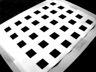
6 6.1 Simulated Experiments For our simulated experiments, we used a diagonal calibration matrix with f = 1000 and τ = 1. Calibration is performed using the projections of the 4 corner points of squares of size 40cm. The distance of the calibration squares to the camera is chosen such that the projections roughly fill the image plane. The projections of the corner points are perturbed by centered Gaussian noise of 0 to 2 pixels variance. In the following, we only display graphs showing the behavior of our algorithm with respect to other parameters than noise; note however that in all cases, the behavior with respect to noise is nearly perfectly linear. The data in the graphs shown stem from experiments with a noise level of 1 pixel. The errors shown in the graphs are absolute errors (the errors for the aspect ratio are scaled by 1000). Each point in a graph represents the median error of 1000 calibration experiments. The graphs of the mean errors are very similar, though slightly less smooth. Figure 1: Scenarios for simulated experiments. One plane seen in one view. The scenario of the first experiment is depicted in the left part of figure 1. Calibration is performed for different orientations of the square, that range from 0 (parallel to the image plane) to 90 (perpendicular to the image plane). The results of calibrating the aspect ratio and the focal length (the principal points is given) are shown in the left-hand part of figure 2. An obvious observation is the presence of singularities: the error of the aspect ratio increases considerably as the calibration square tends to be perpendicular to the image plane (90 ). The determination of the focal length is impossible for the extreme cases of parallelism and perpendicularity. Note that these observations are all predicted by table 1. In the range of [30, 70 ], which should cover the majority of practical situations, the relative error for the focal length is below 1%, while the aspect ratio is estimated correctly within 0.01%. Calibration error Aspect ratio, x1000 Focal length Angle Calibration error Aspect ratio, x1000 Focal length Aspect ratio (standard), x1000 Focal length (standard) Angle Figure 2: Simulation results for one- and two-plane calibration. 6


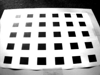
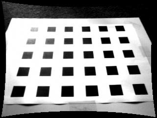
7 Two planes seen in one view. In the second scenario (cf. right part of figure 1), calibration is performed with a camera rotating about its optical axis by 0 to 90. Two calibration planes with an opening angle of 90 are observed. Plane-based calibration is now done without any prior knowledge of intrinsic parameters. For comparison, we also calibrate the camera with a standard method, using full 3D coordinates of the corner points as input. The results are shown in the right hand part of figure 2. As expected, the standard calibration approach is virtually insensitive to rotation about the optical axis. As for the planebased method, the singularities for the estimation of the aspect ratio and the focal length for rotation angles of 0 and 90 are predicted by table 2 (the reflection constraint is satisfied, the planes are parallel to either u or v axis and the vanishing lines intersect above or at the same height as the principal point). As for the intermediate range of orientations, we note that the estimation of the aspect ratio by the plane-based method is 3 to 4 times worse than with the standard approach, although it is still quite accurate. As for the focal length, the plane-based estimate is even slightly better for orientations between 30 and 70. The error graphs for u 0 and v 0 are not shown; for both methods they are nearly horizontal (which means that there is no singularity), the errors of the plane-based estimation being about 30% lower than with the standard approach. 6.2 Calibration Grid We calibrated a camera from images of a 3D calibration grid with targets arranged in three planes (cf. figure 3). For comparison, calibration was also carried out using a standard method. We report here the results of two different experiments. First, 4 images were taken from different positions, but with fixed calibration. The camera was calibrated from single views in different modes: standard calibration using all points, standard calibration with points from two planes only, plane-based calibration from one, two or three planes with different levels of prior knowledge (cf. table 3). Prior values were taken from the results of standard calibration. Table 3 shows the mean values and standard deviation of the calibration results, computed over the 4 different views used and over all possible combinations of planes. We note that even the one-plane method gives results very close to those of the standard method that uses all available points and their full 3D coordinates. The precision of the plane-based results is lower than for full standard calibration, though comparable to standard calibration using points on two planes. An important observation is that the results are very accurate despite the proximity to singular configurations. This may be attributed to the very high accuracy of the data. Figure 3: Images of calibration grid and lab scene. For the second experiment with the calibration grid, we took images at 5 different zoom positions. The camera was calibrated using the 5 3 calibration planes simultaneously, where for each view an individual focal length and principal point was estimated. Table 4 shows the results for the focal lengths, compared to the results of standard calibration from the single views at each zoom position. The deviation increases with the focal length, but the errors stay well below the 1% mark (if we take the results of standard calibration as ground truth). 6.3 Lab Scene A pair of images of an ordinary lab scene were taken. A rectangular part of a computer tower (cf. figure 3) was used for calibration. Subsequently, the pose of the views with respect to the calibration plane was determined. The three points shown in figure 3 were triangulated and their 3D distances measured and compared to hand-measured ones. The differences for the 7


8 Method τ f u 0 v 0 Standard calibration from three planes ± ± ± ± 1.8 Standard calibration from two planes ± ± ± ± 2.6 One plane, u 0, v 0 known ± ± ± ± 1.6 One plane, τ, u 0, v 0 known ± ± ± ± 1.6 Two planes, nothing known ± ± ± ± 2.4 Two planes, τ known ± ± ± ± 1.4 Two planes, u 0, v 0 known ± ± ± ± 1.6 Two planes, τ, u 0, v 0 known ± ± ± ± 1.6 Three planes, nothing known ± ± ± ± 0.5 Table 3: Results of calibration using calibration grid. Method Focal lengths Standard Plane-based Table 4: Calibration results with variable focal length. distances 1-2, 1-3 and 2-3 were 4mm, 3mm and 0mm respectively, for absolute distances of 275mm, 347mm and 214mm. These results are about as good as we might expect: the edges of the rectangular patch are rounded, thus not reliably extracted in the images. The measured point distances are extrapolated from this rectangle, thus amplifying the errors of edge extraction. Another result concerns the epipolar geometry of the image pair that was computed from calibration and pose, shown in figure 4. The distance of points to epipolar lines computed from corresponding points in the other image is about 1 pixel, even at the borders of the image. This simple experiment highlights two important issues. First, besides calibrating the views, we readily obtain their pose in a metric 3D frame. Second, we obtain reasonable estimates of matching constraints, potentially for distant views. These aspects are further discussed in the following section. Figure 4: Computed epipolar geometry for lab scene. 6.4 Distortion Removal On top of calibrating the intrinsic parameters of the pinhole model, it is in practice often necessary to also calibrate distortion parameters. Figure 5 shows an example, where this was done via a straightforward bundle adjustment type non-linear optimisation of all involved parameters (intrinsic parameters, including radial distortion, and the pose of all views), starting from an initialisation with the above described method. 7 Applications Cheap Calibration Tool. Planar patterns are easy to produce and cheap, while enabling a reasonably reliable calibration. Ground Plane Calibration. We have successfully performed experiments with images of traffic scenes. Ground plane calibration is used to restrict the pose of vehicles to be detected and tracked. An example is shown in appendix A.1. 8
9 Reconstruction of Piecewise Planar Objects from Single Views. Using geometrical constraints such as coplanarity, parallelism, right angles etc., 3D objects may be reconstructed from a single view (see e.g. [9]). Our calibration method requires knowledge of the metric structure of planes. This requirement may be relaxed by simultaneously determining calibration and plane structure. For example, from a single view of a planar patch that is known to be rectangular, we are able to determine the ratio of the rectangle s edge lengths as well as the focal length using linear equations. We are currently examining this in combination with coplanarity constraints for the purpose of reconstructing objects from single views. Examples are shown in appendix A.2. Reconstruction of Indoor Scenes from Many Views. Our calibration method is the central part of ongoing work on a system for interactive multi-view 3D reconstruction of indoor scenes, similar in spirit to the approaches presented in [9, 10]. The main motivation for using plane-based calibration is to make a compromise between requirements on flexibility, user interaction and implementation cost. We achieve flexibility by not requiring off-line calibration: our calibration patterns, planar objects, are omnipresent in indoor scenes. The amount of user interactions is rather little: we usually use rectangles as calibration objects; they have to be delineated in images and their edge lengths measured (this might also be avoided as indicated above). By identifying planar patterns across distant views, we not only can simultaneously calibrate many views but also compute a global initial pose of many views to bootstrap wide baseline matching for example. The pose and calibration of intermediate views can be interpolated from neighboring already calibrated views using local structure from motion techniques. This scheme relies on methods that are relatively simple to implement and might provide a useful alternative to completely automatic techniques such as [8] that are more flexible but more difficult to realise. Augmented Reality. A nice and useful application of plane-based calibration and pose determination is presented in [5]. Rectangular plates are used to mark the position and orientation of non planar objects to be added to a video sequence, which is in some way a generalisation of overpainting planar surfaces in videos by homography projection of a desired pattern. Plane-based methods may also be used for blue screening; attaching calibration patterns on the blue screen allows to track camera pose and calibration and thus to provide input for positioning objects in augmented reality. 8 Conclusion and Perspectives We presented a general and easy to implement plane-based calibration method that is suitable for calibrating variable intrinsic parameters and that copes with any number of calibration planes and views. Experimental results are very satisfactory. For the basic cases of using one or two planes, we gave an exhaustive list of singularities, thus allowing to avoid them deliberately and obtain reliable results. Several applications of plane-based calibration were described. Ongoing work is mainly focused on the completion of an interactive system for 3D reconstruction of indoor scenes from many images, that is mainly based on our calibration method. An analytical error analysis might be fruitful, i.e. examining the influence of feature extraction errors on calibration accuracy. References [1] A. Criminisi, I. Reid, A. Zisserman, Duality, Rigidity and Planar Parallax, ECCV, pp , June [2] O. Faugeras, Stratification of Three-Dimensional Vision: Projective, Affine and Metric Representations, Journal of the Optical Society of America A, Vol. 12, pp , [3] R.J. Holt, A.N. Netravali, Camera Calibration Problem: Some New Results, CVIU, Vol. 54, No. 3, pp , [4] A. Jennings, J.J. McKeown, Matrix Computation, 2nd edition, Wiley, [5] M. Jethwa, A. Zisserman, A. Fitzgibbon, Real-time Panoramic Mosaics and Augmented Reality, BMVC, pp , September [6] R.K. Lenz, R.Y. Tsai, Techniques for Calibration of the Scale Factor and Image Center for High Accuracy 3-D Machine Vision Metrology, PAMI, Vol. 10, No. 5, pp , [7] F. Pedersini, A. Sarti, S. Tubaro, Multi-Camera Acquisitions for High-Accuracy 3D Reconstruction, SMILE Workshop, Freiburg, Germany, pp , June [8] M. Pollefeys, R. Koch, M. Vergauwen, L. Van Gool, Metric 3D Surface Reconstruction from Uncalibrated Image Sequences, SMILE Workshop, Freiburg, Germany, pp , June
10 [9] H.-Y. Shum, R. Szeliski, S. Baker, M. Han, P. Anandan, Interactive 3D Modeling from Multiple Images Using Scene Regularities, SMILE Workshop, Freiburg, Germany, pp , June [10] R. Szeliski, P.H.S. Torr, Geometrically Constrained Structure from Motion: Points on Planes, SMILE Workshop, Freiburg, Germany, pp , June [11] R.Y. Tsai, A Versatile Camera Calibration Technique for High-Accuracy 3D Machine Vision Metrology Using Off-the- Shelf TV Cameras and Lenses, IEEE Journal of Robotics and Automation, Vol. 3, No. 4, pp , [12] B. Triggs, Autocalibration from planar scenes, ECCV, pp , June [13] G.-Q. Wei, S.D. Ma, A Complete Two-Plane Camera Calibration Method and Experimental Comparisons, ICCV, pp , A Examples A.1 Vehicle Detection Figure 6 shows an image taken by a camera mounted on a vehicle. Road markers and their normed distances have been used to calibrate the focal length of the camera as well as its full 3D position with respect to the ground plane (i.e. height, pan and tilt). This information has then been used to locate vehicles on the ground plane. There are three free parameters for this: two position and one rotation parameters. Figures 7 and 8 show best fit localizations with the 3D generic car models projected into the image. Despite the fact that the accuracy in road marker extraction in the image is quite low and that we use minimal knowledge to calibrate (one image and one plane), the results are comparable to a previous method that uses two images, more 3D information (a feature perpendicular to the ground plane is needed) and that needs manual input of the camera height above the ground plane. 10
11 11
12 Figure 6: Road markers used for ground plane calibration. Figure 7: 3D car model overlaid on the image. 12

13 Figure 8: 3D car model overlaid on the image. 13

14 A.2 Reconstruction of Piecewise Planar Objects from Single Views The images in figures 9 and 14 have been used to calibrate the focal length of the cameras and obtain 3D models of the buildings shown. Texture has been mapped from the original images onto the 3D models. Rendered views of the models are shown in figures 10 to 18. Note that for the second building, the original image in figure 14 does not give sufficient texture information for some walls. In this case, for better visualization, we added texture maps from additional close-up views. Input needed for calibration and 3D reconstruction are coplanarity, perpendicularity and parallelism constraints. The complete method will soon be described in a separate article. Figure 9: Image used for 3D reconstruction and texture mapping. 14


15 Figure 10: Sample view of the 3D model. Figure 11: Sample view of the 3D model. 15

16 Figure 12: Sample view of the 3D model. 16

17 Figure 13: Sample view of the 3D model. 17

18 Figure 14: Image used for 3D reconstruction and texture mapping. 18

19 Figure 15: Sample view of the 3D model. 19

20 Figure 16: Sample view of the 3D model. 20

21 Figure 17: Sample view of the 3D model. 21

22 Figure 18: Sample view of the 3D model. 22
On Plane-Based Camera Calibration: A General Algorithm, Singularities, Applications
 On Plane-Based Camera Calibration: A General Algorithm, Singularities, Applications Peter Sturm, Steve Maybank To cite this version: Peter Sturm, Steve Maybank. On Plane-Based Camera Calibration: A General
A Method for Interactive 3D Reconstruction of Piecewise Planar Objects from Single Images
 A Method for Interactive 3D Reconstruction of Piecewise Planar Objects from Single Images Peter F Sturm and Stephen J Maybank Computational Vision Group, Department of Computer Science The University of
A Method for Interactive 3D Reconstruction of Piecewise Planar Objects from Single Images
 A Method for Interactive 3D Reconstruction of Piecewise Planar Objects from Single Images Peter Sturm Steve Maybank To cite this version: Peter Sturm Steve Maybank A Method for Interactive 3D Reconstruction
calibrated coordinates Linear transformation pixel coordinates
 1 calibrated coordinates Linear transformation pixel coordinates 2 Calibration with a rig Uncalibrated epipolar geometry Ambiguities in image formation Stratified reconstruction Autocalibration with partial
Critical Motion Sequences for the Self-Calibration of Cameras and Stereo Systems with Variable Focal Length
 Critical Motion Sequences for the Self-Calibration of Cameras and Stereo Systems with Variable Focal Length Peter F Sturm Computational Vision Group, Department of Computer Science The University of Reading,
Camera Calibration and 3D Reconstruction from Single Images Using Parallelepipeds
 Camera Calibration and 3D Reconstruction from Single Images Using Parallelepipeds Marta Wilczkowiak Edmond Boyer Peter Sturm Movi Gravir Inria Rhône-Alpes, 655 Avenue de l Europe, 3833 Montbonnot, France
Euclidean Reconstruction Independent on Camera Intrinsic Parameters
 Euclidean Reconstruction Independent on Camera Intrinsic Parameters Ezio MALIS I.N.R.I.A. Sophia-Antipolis, FRANCE Adrien BARTOLI INRIA Rhone-Alpes, FRANCE Abstract bundle adjustment techniques for Euclidean
Compositing a bird's eye view mosaic
 Compositing a bird's eye view mosaic Robert Laganiere School of Information Technology and Engineering University of Ottawa Ottawa, Ont KN 6N Abstract This paper describes a method that allows the composition
Camera Calibration from the Quasi-affine Invariance of Two Parallel Circles
 Camera Calibration from the Quasi-affine Invariance of Two Parallel Circles Yihong Wu, Haijiang Zhu, Zhanyi Hu, and Fuchao Wu National Laboratory of Pattern Recognition, Institute of Automation, Chinese
3D reconstruction class 11
 3D reconstruction class 11 Multiple View Geometry Comp 290-089 Marc Pollefeys Multiple View Geometry course schedule (subject to change) Jan. 7, 9 Intro & motivation Projective 2D Geometry Jan. 14, 16
Camera model and multiple view geometry
 Chapter Camera model and multiple view geometry Before discussing how D information can be obtained from images it is important to know how images are formed First the camera model is introduced and then
Partial Calibration and Mirror Shape Recovery for Non-Central Catadioptric Systems
 Partial Calibration and Mirror Shape Recovery for Non-Central Catadioptric Systems Abstract In this paper we present a method for mirror shape recovery and partial calibration for non-central catadioptric
Structure from motion
 Structure from motion Structure from motion Given a set of corresponding points in two or more images, compute the camera parameters and the 3D point coordinates?? R 1,t 1 R 2,t R 2 3,t 3 Camera 1 Camera
Robust Camera Calibration from Images and Rotation Data
 Robust Camera Calibration from Images and Rotation Data Jan-Michael Frahm and Reinhard Koch Institute of Computer Science and Applied Mathematics Christian Albrechts University Kiel Herman-Rodewald-Str.
55:148 Digital Image Processing Chapter 11 3D Vision, Geometry
 55:148 Digital Image Processing Chapter 11 3D Vision, Geometry Topics: Basics of projective geometry Points and hyperplanes in projective space Homography Estimating homography from point correspondence
Critical Motion Sequences for the Self-Calibration of Cameras and Stereo Systems with Variable Focal Length
 Critical Motion Sequences for the Self-Calibration of Cameras and Stereo Systems with Variable Focal Length Peter Sturm To cite this version: Peter Sturm. Critical Motion Sequences for the Self-Calibration
arxiv: v1 [cs.cv] 28 Sep 2018
![arxiv: v1 [cs.cv] 28 Sep 2018](/thumbs/93/113542646.jpg "arxiv: v1 [cs.cv] 28 Sep 2018") Camera Pose Estimation from Sequence of Calibrated Images arxiv:1809.11066v1 [cs.cv] 28 Sep 2018 Jacek Komorowski 1 and Przemyslaw Rokita 2 1 Maria Curie-Sklodowska University, Institute of Computer Science,
Camera Pose Estimation from Sequence of Calibrated Images arxiv:1809.11066v1 [cs.cv] 28 Sep 2018 Jacek Komorowski 1 and Przemyslaw Rokita 2 1 Maria Curie-Sklodowska University, Institute of Computer Science,
Stereo Image Rectification for Simple Panoramic Image Generation
 Stereo Image Rectification for Simple Panoramic Image Generation Yun-Suk Kang and Yo-Sung Ho Gwangju Institute of Science and Technology (GIST) 261 Cheomdan-gwagiro, Buk-gu, Gwangju 500-712 Korea Email:{yunsuk,
Metric Rectification for Perspective Images of Planes
 789139-3 University of California Santa Barbara Department of Electrical and Computer Engineering CS290I Multiple View Geometry in Computer Vision and Computer Graphics Spring 2006 Metric Rectification
Linear Auto-Calibration for Ground Plane Motion
 Linear Auto-Calibration for Ground Plane Motion Joss Knight, Andrew Zisserman, and Ian Reid Department of Engineering Science, University of Oxford Parks Road, Oxford OX1 3PJ, UK [joss,az,ian]@robots.ox.ac.uk
A Factorization Method for Structure from Planar Motion
 A Factorization Method for Structure from Planar Motion Jian Li and Rama Chellappa Center for Automation Research (CfAR) and Department of Electrical and Computer Engineering University of Maryland, College
Camera Calibration with a Simulated Three Dimensional Calibration Object
 Czech Pattern Recognition Workshop, Tomáš Svoboda (Ed.) Peršlák, Czech Republic, February 4, Czech Pattern Recognition Society Camera Calibration with a Simulated Three Dimensional Calibration Object Hynek
METRIC PLANE RECTIFICATION USING SYMMETRIC VANISHING POINTS
 METRIC PLANE RECTIFICATION USING SYMMETRIC VANISHING POINTS M. Lefler, H. Hel-Or Dept. of CS, University of Haifa, Israel Y. Hel-Or School of CS, IDC, Herzliya, Israel ABSTRACT Video analysis often requires
BIL Computer Vision Apr 16, 2014
 BIL 719 - Computer Vision Apr 16, 2014 Binocular Stereo (cont d.), Structure from Motion Aykut Erdem Dept. of Computer Engineering Hacettepe University Slide credit: S. Lazebnik Basic stereo matching algorithm
Flexible Calibration of a Portable Structured Light System through Surface Plane
 Vol. 34, No. 11 ACTA AUTOMATICA SINICA November, 2008 Flexible Calibration of a Portable Structured Light System through Surface Plane GAO Wei 1 WANG Liang 1 HU Zhan-Yi 1 Abstract For a portable structured
Structure from motion
 Structure from motion Structure from motion Given a set of corresponding points in two or more images, compute the camera parameters and the 3D point coordinates?? R 1,t 1 R 2,t 2 R 3,t 3 Camera 1 Camera
Feature Transfer and Matching in Disparate Stereo Views through the use of Plane Homographies
 Feature Transfer and Matching in Disparate Stereo Views through the use of Plane Homographies M. Lourakis, S. Tzurbakis, A. Argyros, S. Orphanoudakis Computer Vision and Robotics Lab (CVRL) Institute of
Coplanar circles, quasi-affine invariance and calibration
 Image and Vision Computing 24 (2006) 319 326 www.elsevier.com/locate/imavis Coplanar circles, quasi-affine invariance and calibration Yihong Wu *, Xinju Li, Fuchao Wu, Zhanyi Hu National Laboratory of
A General Expression of the Fundamental Matrix for Both Perspective and Affine Cameras
 A General Expression of the Fundamental Matrix for Both Perspective and Affine Cameras Zhengyou Zhang* ATR Human Information Processing Res. Lab. 2-2 Hikari-dai, Seika-cho, Soraku-gun Kyoto 619-02 Japan
More on single-view geometry class 10
 More on single-view geometry class 10 Multiple View Geometry Comp 290-089 Marc Pollefeys Multiple View Geometry course schedule (subject to change) Jan. 7, 9 Intro & motivation Projective 2D Geometry Jan.
Vision Review: Image Formation. Course web page:
 Vision Review: Image Formation Course web page: www.cis.udel.edu/~cer/arv September 10, 2002 Announcements Lecture on Thursday will be about Matlab; next Tuesday will be Image Processing The dates some
Camera Calibration. Schedule. Jesus J Caban. Note: You have until next Monday to let me know. ! Today:! Camera calibration
 Camera Calibration Jesus J Caban Schedule! Today:! Camera calibration! Wednesday:! Lecture: Motion & Optical Flow! Monday:! Lecture: Medical Imaging! Final presentations:! Nov 29 th : W. Griffin! Dec 1
Homogeneous Coordinates. Lecture18: Camera Models. Representation of Line and Point in 2D. Cross Product. Overall scaling is NOT important.
 Homogeneous Coordinates Overall scaling is NOT important. CSED44:Introduction to Computer Vision (207F) Lecture8: Camera Models Bohyung Han CSE, POSTECH bhhan@postech.ac.kr (",, ) ()", ), )) ) 0 It is
Multiple Views Geometry
 Multiple Views Geometry Subhashis Banerjee Dept. Computer Science and Engineering IIT Delhi email: suban@cse.iitd.ac.in January 2, 28 Epipolar geometry Fundamental geometric relationship between two perspective
3D Reconstruction from Scene Knowledge
 Multiple-View Reconstruction from Scene Knowledge 3D Reconstruction from Scene Knowledge SYMMETRY & MULTIPLE-VIEW GEOMETRY Fundamental types of symmetry Equivalent views Symmetry based reconstruction MUTIPLE-VIEW
Camera Models and Image Formation. Srikumar Ramalingam School of Computing University of Utah
 Camera Models and Image Formation Srikumar Ramalingam School of Computing University of Utah srikumar@cs.utah.edu Reference Most slides are adapted from the following notes: Some lecture notes on geometric
COMPARATIVE STUDY OF DIFFERENT APPROACHES FOR EFFICIENT RECTIFICATION UNDER GENERAL MOTION
 COMPARATIVE STUDY OF DIFFERENT APPROACHES FOR EFFICIENT RECTIFICATION UNDER GENERAL MOTION Mr.V.SRINIVASA RAO 1 Prof.A.SATYA KALYAN 2 DEPARTMENT OF COMPUTER SCIENCE AND ENGINEERING PRASAD V POTLURI SIDDHARTHA
An Overview of Matchmoving using Structure from Motion Methods
 An Overview of Matchmoving using Structure from Motion Methods Kamyar Haji Allahverdi Pour Department of Computer Engineering Sharif University of Technology Tehran, Iran Email: allahverdi@ce.sharif.edu
Camera Models and Image Formation. Srikumar Ramalingam School of Computing University of Utah
 Camera Models and Image Formation Srikumar Ramalingam School of Computing University of Utah srikumar@cs.utah.edu VisualFunHouse.com 3D Street Art Image courtesy: Julian Beaver (VisualFunHouse.com) 3D
Multiple View Geometry in computer vision
 Multiple View Geometry in computer vision Chapter 8: More Single View Geometry Olaf Booij Intelligent Systems Lab Amsterdam University of Amsterdam, The Netherlands HZClub 29-02-2008 Overview clubje Part
Computer Vision Projective Geometry and Calibration. Pinhole cameras
 Computer Vision Projective Geometry and Calibration Professor Hager http://www.cs.jhu.edu/~hager Jason Corso http://www.cs.jhu.edu/~jcorso. Pinhole cameras Abstract camera model - box with a small hole
Multiple View Geometry in Computer Vision Second Edition
 Multiple View Geometry in Computer Vision Second Edition Richard Hartley Australian National University, Canberra, Australia Andrew Zisserman University of Oxford, UK CAMBRIDGE UNIVERSITY PRESS Contents
Hand-Eye Calibration from Image Derivatives
 Hand-Eye Calibration from Image Derivatives Abstract In this paper it is shown how to perform hand-eye calibration using only the normal flow field and knowledge about the motion of the hand. The proposed
EXAM SOLUTIONS. Image Processing and Computer Vision Course 2D1421 Monday, 13 th of March 2006,
 School of Computer Science and Communication, KTH Danica Kragic EXAM SOLUTIONS Image Processing and Computer Vision Course 2D1421 Monday, 13 th of March 2006, 14.00 19.00 Grade table 0-25 U 26-35 3 36-45
A Case Against Kruppa s Equations for Camera Self-Calibration
 EXTENDED VERSION OF: ICIP - IEEE INTERNATIONAL CONFERENCE ON IMAGE PRO- CESSING, CHICAGO, ILLINOIS, PP. 172-175, OCTOBER 1998. A Case Against Kruppa s Equations for Camera Self-Calibration Peter Sturm
Camera Calibration and Light Source Orientation Estimation from Images with Shadows
 Camera Calibration and Light Source Orientation Estimation from Images with Shadows Xiaochun Cao and Mubarak Shah Computer Vision Lab University of Central Florida Orlando, FL, 32816-3262 Abstract In this
Computer Vision: Lecture 3
 Computer Vision: Lecture 3 Carl Olsson 2019-01-29 Carl Olsson Computer Vision: Lecture 3 2019-01-29 1 / 28 Todays Lecture Camera Calibration The inner parameters - K. Projective vs. Euclidean Reconstruction.
Mei Han Takeo Kanade. January Carnegie Mellon University. Pittsburgh, PA Abstract
 Scene Reconstruction from Multiple Uncalibrated Views Mei Han Takeo Kanade January 000 CMU-RI-TR-00-09 The Robotics Institute Carnegie Mellon University Pittsburgh, PA 1513 Abstract We describe a factorization-based
Today. Stereo (two view) reconstruction. Multiview geometry. Today. Multiview geometry. Computational Photography
 reconstruction. Multiview geometry. Today. Multiview geometry. Computational Photography") Computational Photography Matthias Zwicker University of Bern Fall 2009 Today From 2D to 3D using multiple views Introduction Geometry of two views Stereo matching Other applications Multiview geometry
Computational Photography Matthias Zwicker University of Bern Fall 2009 Today From 2D to 3D using multiple views Introduction Geometry of two views Stereo matching Other applications Multiview geometry
1 Projective Geometry
 CIS8, Machine Perception Review Problem - SPRING 26 Instructions. All coordinate systems are right handed. Projective Geometry Figure : Facade rectification. I took an image of a rectangular object, and
Multiple Motion Scene Reconstruction from Uncalibrated Views
 Multiple Motion Scene Reconstruction from Uncalibrated Views Mei Han C & C Research Laboratories NEC USA, Inc. meihan@ccrl.sj.nec.com Takeo Kanade Robotics Institute Carnegie Mellon University tk@cs.cmu.edu
Combining Off- and On-line Calibration of a Digital Camera
 Combining ff- and n-line Calibration of a Digital Camera Magdalena Urbanek, Radu Horaud and Peter Sturm INRIA Rhône-Alpes 655, avenue de l Europe, 38334 Saint Ismier Cedex, France {MagdalenaUrbanek, RaduHoraud,
A COMPREHENSIVE TOOL FOR RECOVERING 3D MODELS FROM 2D PHOTOS WITH WIDE BASELINES
 A COMPREHENSIVE TOOL FOR RECOVERING 3D MODELS FROM 2D PHOTOS WITH WIDE BASELINES Yuzhu Lu Shana Smith Virtual Reality Applications Center, Human Computer Interaction Program, Iowa State University, Ames,
Computer Vision I - Algorithms and Applications: Multi-View 3D reconstruction
 Computer Vision I - Algorithms and Applications: Multi-View 3D reconstruction Carsten Rother 09/12/2013 Computer Vision I: Multi-View 3D reconstruction Roadmap this lecture Computer Vision I: Multi-View
Recovery of Intrinsic and Extrinsic Camera Parameters Using Perspective Views of Rectangles
 177 Recovery of Intrinsic and Extrinsic Camera Parameters Using Perspective Views of Rectangles T. N. Tan, G. D. Sullivan and K. D. Baker Department of Computer Science The University of Reading, Berkshire
How to Compute the Pose of an Object without a Direct View?
 How to Compute the Pose of an Object without a Direct View? Peter Sturm and Thomas Bonfort INRIA Rhône-Alpes, 38330 Montbonnot St Martin, France {Peter.Sturm, Thomas.Bonfort}@inrialpes.fr Abstract. We
Stereo and Epipolar geometry
 Previously Image Primitives (feature points, lines, contours) Today: Stereo and Epipolar geometry How to match primitives between two (multiple) views) Goals: 3D reconstruction, recognition Jana Kosecka
A simple method for interactive 3D reconstruction and camera calibration from a single view
 A simple method for interactive 3D reconstruction and camera calibration from a single view Akash M Kushal Vikas Bansal Subhashis Banerjee Department of Computer Science and Engineering Indian Institute
Stereo Vision. MAN-522 Computer Vision
 Stereo Vision MAN-522 Computer Vision What is the goal of stereo vision? The recovery of the 3D structure of a scene using two or more images of the 3D scene, each acquired from a different viewpoint in
Partial Calibration and Mirror Shape Recovery for Non-Central Catadioptric Systems
 Partial Calibration and Mirror Shape Recovery for Non-Central Catadioptric Systems Nuno Gonçalves and Helder Araújo Institute of Systems and Robotics - Coimbra University of Coimbra Polo II - Pinhal de
Fundamentals of Stereo Vision Michael Bleyer LVA Stereo Vision
 Fundamentals of Stereo Vision Michael Bleyer LVA Stereo Vision What Happened Last Time? Human 3D perception (3D cinema) Computational stereo Intuitive explanation of what is meant by disparity Stereo matching
Computer Vision. Coordinates. Prof. Flávio Cardeal DECOM / CEFET- MG.
 Computer Vision Coordinates Prof. Flávio Cardeal DECOM / CEFET- MG cardeal@decom.cefetmg.br Abstract This lecture discusses world coordinates and homogeneous coordinates, as well as provides an overview
Linear Multi-View Reconstruction of Points, Lines, Planes and Cameras using a Reference Plane
 Linear Multi-View Reconstruction of Points, Lines, Planes and Cameras using a Reference Plane Carsten Rother Computational Vision and Active Perception Laboratory (CVAP) Royal Institute of Technology (KTH),
A Desktop 3D Scanner Exploiting Rotation and Visual Rectification of Laser Profiles
 A Desktop 3D Scanner Exploiting Rotation and Visual Rectification of Laser Profiles Carlo Colombo, Dario Comanducci, and Alberto Del Bimbo Dipartimento di Sistemi ed Informatica Via S. Marta 3, I-5139
Two-view geometry Computer Vision Spring 2018, Lecture 10
 Two-view geometry http://www.cs.cmu.edu/~16385/ 16-385 Computer Vision Spring 2018, Lecture 10 Course announcements Homework 2 is due on February 23 rd. - Any questions about the homework? - How many of
COSC579: Scene Geometry. Jeremy Bolton, PhD Assistant Teaching Professor
 COSC579: Scene Geometry Jeremy Bolton, PhD Assistant Teaching Professor Overview Linear Algebra Review Homogeneous vs non-homogeneous representations Projections and Transformations Scene Geometry The
Using Pedestrians Walking on Uneven Terrains for Camera Calibration
 Machine Vision and Applications manuscript No. (will be inserted by the editor) Using Pedestrians Walking on Uneven Terrains for Camera Calibration Imran N. Junejo Department of Computer Science, University
Perception and Action using Multilinear Forms
 Perception and Action using Multilinear Forms Anders Heyden, Gunnar Sparr, Kalle Åström Dept of Mathematics, Lund University Box 118, S-221 00 Lund, Sweden email: {heyden,gunnar,kalle}@maths.lth.se Abstract
Camera Calibration and Light Source Estimation from Images with Shadows
 Camera Calibration and Light Source Estimation from Images with Shadows Xiaochun Cao and Mubarak Shah Computer Vision Lab, University of Central Florida, Orlando, FL, 32816 Abstract In this paper, we describe
Pin Hole Cameras & Warp Functions
 Pin Hole Cameras & Warp Functions Instructor - Simon Lucey 16-423 - Designing Computer Vision Apps Today Pinhole Camera. Homogenous Coordinates. Planar Warp Functions. Example of SLAM for AR Taken from:
An idea which can be used once is a trick. If it can be used more than once it becomes a method
 An idea which can be used once is a trick. If it can be used more than once it becomes a method - George Polya and Gabor Szego University of Texas at Arlington Rigid Body Transformations & Generalized
A linear algorithm for Camera Self-Calibration, Motion and Structure Recovery for Multi-Planar Scenes from Two Perspective Images
 A linear algorithm for Camera Self-Calibration, Motion and Structure Recovery for Multi-Planar Scenes from Two Perspective Images Gang Xu, Jun-ichi Terai and Heung-Yeung Shum Microsoft Research China 49
Unit 3 Multiple View Geometry
 Unit 3 Multiple View Geometry Relations between images of a scene Recovering the cameras Recovering the scene structure http://www.robots.ox.ac.uk/~vgg/hzbook/hzbook1.html 3D structure from images Recover
Multi-Camera Calibration with One-Dimensional Object under General Motions
 Multi-Camera Calibration with One-Dimensional Obect under General Motions L. Wang, F. C. Wu and Z. Y. Hu National Laboratory of Pattern Recognition, Institute of Automation, Chinese Academy of Sciences,
Index. 3D reconstruction, point algorithm, point algorithm, point algorithm, point algorithm, 263
 Index 3D reconstruction, 125 5+1-point algorithm, 284 5-point algorithm, 270 7-point algorithm, 265 8-point algorithm, 263 affine point, 45 affine transformation, 57 affine transformation group, 57 affine
Visual Recognition: Image Formation
 Visual Recognition: Image Formation Raquel Urtasun TTI Chicago Jan 5, 2012 Raquel Urtasun (TTI-C) Visual Recognition Jan 5, 2012 1 / 61 Today s lecture... Fundamentals of image formation You should know
Midterm Exam Solutions
 Midterm Exam Solutions Computer Vision (J. Košecká) October 27, 2009 HONOR SYSTEM: This examination is strictly individual. You are not allowed to talk, discuss, exchange solutions, etc., with other fellow
Index. 3D reconstruction, point algorithm, point algorithm, point algorithm, point algorithm, 253
 Index 3D reconstruction, 123 5+1-point algorithm, 274 5-point algorithm, 260 7-point algorithm, 255 8-point algorithm, 253 affine point, 43 affine transformation, 55 affine transformation group, 55 affine
ECE Digital Image Processing and Introduction to Computer Vision. Outline
 ECE592-064 Digital Image Processing and Introduction to Computer Vision Depart. of ECE, NC State University Instructor: Tianfu (Matt) Wu Spring 2017 1. Recap Outline 2. Modeling Projection and Projection
Camera Geometry II. COS 429 Princeton University
 Camera Geometry II COS 429 Princeton University Outline Projective geometry Vanishing points Application: camera calibration Application: single-view metrology Epipolar geometry Application: stereo correspondence
Practical Camera Auto-Calibration Based on Object Appearance and Motion for Traffic Scene Visual Surveillance
 Practical Camera Auto-Calibration Based on Object Appearance and Motion for Traffic Scene Visual Surveillance Zhaoxiang Zhang, Min Li, Kaiqi Huang and Tieniu Tan National Laboratory of Pattern Recognition,
Structured Light II. Thanks to Ronen Gvili, Szymon Rusinkiewicz and Maks Ovsjanikov
 Structured Light II Johannes Köhler Johannes.koehler@dfki.de Thanks to Ronen Gvili, Szymon Rusinkiewicz and Maks Ovsjanikov Introduction Previous lecture: Structured Light I Active Scanning Camera/emitter
Stereo II CSE 576. Ali Farhadi. Several slides from Larry Zitnick and Steve Seitz
 Stereo II CSE 576 Ali Farhadi Several slides from Larry Zitnick and Steve Seitz Camera parameters A camera is described by several parameters Translation T of the optical center from the origin of world
Camera Calibration using Vanishing Points
 Camera Calibration using Vanishing Points Paul Beardsley and David Murray * Department of Engineering Science, University of Oxford, Oxford 0X1 3PJ, UK Abstract This paper describes a methodformeasuringthe
Calibrating a Structured Light System Dr Alan M. McIvor Robert J. Valkenburg Machine Vision Team, Industrial Research Limited P.O. Box 2225, Auckland
 Calibrating a Structured Light System Dr Alan M. McIvor Robert J. Valkenburg Machine Vision Team, Industrial Research Limited P.O. Box 2225, Auckland New Zealand Tel: +64 9 3034116, Fax: +64 9 302 8106
Camera Calibration for Video See-Through Head-Mounted Display. Abstract. 1.0 Introduction. Mike Bajura July 7, 1993
 Camera Calibration for Video See-Through Head-Mounted Display Mike Bajura July 7, 1993 Abstract This report describes a method for computing the parameters needed to model a television camera for video
Camera models and calibration
 Camera models and calibration Read tutorial chapter 2 and 3. http://www.cs.unc.edu/~marc/tutorial/ Szeliski s book pp.29-73 Schedule (tentative) 2 # date topic Sep.8 Introduction and geometry 2 Sep.25
Passive 3D Photography
 SIGGRAPH 2000 Course on 3D Photography Passive 3D Photography Steve Seitz Carnegie Mellon University University of Washington http://www.cs cs.cmu.edu/~ /~seitz Visual Cues Shading Merle Norman Cosmetics,
Segmentation and Tracking of Partial Planar Templates
 Segmentation and Tracking of Partial Planar Templates Abdelsalam Masoud William Hoff Colorado School of Mines Colorado School of Mines Golden, CO 800 Golden, CO 800 amasoud@mines.edu whoff@mines.edu Abstract
CS201 Computer Vision Camera Geometry
 CS201 Computer Vision Camera Geometry John Magee 25 November, 2014 Slides Courtesy of: Diane H. Theriault (deht@bu.edu) Question of the Day: How can we represent the relationships between cameras and the
Lecture 10: Multi view geometry
 Lecture 10: Multi view geometry Professor Fei Fei Li Stanford Vision Lab 1 What we will learn today? Stereo vision Correspondence problem (Problem Set 2 (Q3)) Active stereo vision systems Structure from
The end of affine cameras
 The end of affine cameras Affine SFM revisited Epipolar geometry Two-view structure from motion Multi-view structure from motion Planches : http://www.di.ens.fr/~ponce/geomvis/lect3.pptx http://www.di.ens.fr/~ponce/geomvis/lect3.pdf
Computational Optical Imaging - Optique Numerique. -- Multiple View Geometry and Stereo --
 Computational Optical Imaging - Optique Numerique -- Multiple View Geometry and Stereo -- Winter 2013 Ivo Ihrke with slides by Thorsten Thormaehlen Feature Detection and Matching Wide-Baseline-Matching
Plane-based Calibration Algorithm for Multi-camera Systems via Factorization of Homography Matrices
 Plane-based Calibration Algorithm for Multi-camera Systems via Factorization of Homography Matrices Toshio Ueshiba Fumiaki Tomita National Institute of Advanced Industrial Science and Technology (AIST)
Automatic 3D Model Construction for Turn-Table Sequences - a simplification
 Automatic 3D Model Construction for Turn-Table Sequences - a simplification Fredrik Larsson larsson@isy.liu.se April, Background This report introduces some simplifications to the method by Fitzgibbon
3D Sensing and Reconstruction Readings: Ch 12: , Ch 13: ,
 3D Sensing and Reconstruction Readings: Ch 12: 12.5-6, Ch 13: 13.1-3, 13.9.4 Perspective Geometry Camera Model Stereo Triangulation 3D Reconstruction by Space Carving 3D Shape from X means getting 3D coordinates
Pin Hole Cameras & Warp Functions
 Pin Hole Cameras & Warp Functions Instructor - Simon Lucey 16-423 - Designing Computer Vision Apps Today Pinhole Camera. Homogenous Coordinates. Planar Warp Functions. Motivation Taken from: http://img.gawkerassets.com/img/18w7i1umpzoa9jpg/original.jpg
Lecture 9: Epipolar Geometry
 Lecture 9: Epipolar Geometry Professor Fei Fei Li Stanford Vision Lab 1 What we will learn today? Why is stereo useful? Epipolar constraints Essential and fundamental matrix Estimating F (Problem Set 2
Maximum Likelihood 3D Reconstruction from One or More Images under Geometric Constraints
 Maximum Likelihood 3D Reconstruction from One or More Images under Geometric Constraints Etienne Grossmann and José Santos-Victor {etienne jasv}@isr.ist.utl.pt Abstract We address the 3D reconstruction
MAPI Computer Vision. Multiple View Geometry
 MAPI Computer Vision Multiple View Geometry Geometry o Multiple Views 2- and 3- view geometry p p Kpˆ [ K R t]p Geometry o Multiple Views 2- and 3- view geometry Epipolar Geometry The epipolar geometry