Given: scene specification (object positions, optical properties p of the surface, viewer position, viewing direction, )
|
|
|
- Charles Ethan Parks
- 5 years ago
- Views:
Transcription
1 Illumination and Shading

 Find: intensity for each")
2 Illumination and Shading Given: scene specification (object positions, optical properties p of the surface, viewer position, viewing direction, ) Find: intensity for each pixel viewer image plane light
3 Illumination Models (lighting model, shading model) Photorealism in computer graphics involves Accurate representations of surface properties, and Good physical descriptions of the lighting effects Rendering needs a model for how light interacts with objects. Physically more correct model: the intensity reflected from every point depends on the intensity from every other points global illumination Simplistic model: the intensity depends only on the direct illumination i due to light sources local illumination


4 Light Sources Point light sources Emitting radiant energy at a single point Specified with its position and the color of the emitted light Infinitely distant light sources A large light source, such as sun, that is very far from a scene Little variation in its directional effects Specified with its color value and a fixed direction for the light rays Arjan Kok


5 Light Sources Directional light sources Produces a directional beam of light Spotlight effects Area light sources
6 Light Sources Radial intensity attenuation As radiant energy travels, its amplitude is attenuated by the 2 factor 1 / d Sometimes, more realistic attenuation effects can be obtained with an inverse quadratic function of distance f = a a d + a d if if source is at infinity source is local The intensity attenuation is not applied to light sources at infinity because all points in the scene are at a nearly equal distance from a far-off source
 = cos n")
7 Light Sources Angular intensity attenuation For a directional light, we can attenuate the light intensity angularly as well as radially f ( α ) = cos n α
8 Surface Lighting Effects An illumination model computes the lighting effects for a surface using the various optical properties Degree of transparency, color reflectance, surface texture The reflection model describes the way incident light reflects from an opaque surface Diffuse, ambient, specular reflections Simple approximation of actual physical models This model is known as: shading model lighting model light reflection model local illumination model Phong illumination model reflectance model
9 Ambient Light Multiple reflection of nearby objects (light-reflecting sources) yields a uniform illumination Ambient light is independent of light sources and viewer position Ambient illumination is constant for an object, without regard to directions of faces I = kaia I : the incident ambient intensity a : ambient reflection coefficient, ka the proportion reflected away from the surface Indirect illumination can be computed much better: Indirect illumination can be computed much better: e.g. radiosity
10 Wavelength dependence ka I and are function over all wavelengths. a Ideally, we need I ( λ) = ka( λ) Ia( λ) λ Calculate RGB component separately: I red = k a,red I a,red I green=ka,green Ia,green I blue = k a,blue I a,blue
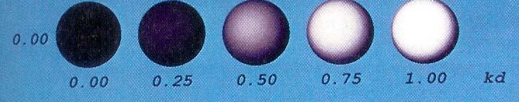
11 Diffuse Reflection Matte (dull) surfaces diffuse incident light uniformly to every direction (light intensity it is independent d of angle of reflection) Such surfaces are called ideal diffuse reflectors (also referred to as Lambertian reflectors) )

12 Diffuse Reflection Light intensity depends on angle of incidence Light intensity is independent of angle of reflection
13 Diffuse Reflection Light intensity depends on angle of incidence Light intensity is independent of angle of reflection I = k I cosθ = d l k d I l ( N L) I l : the intensity of the light source k : diffuse reflection coefficient, d N : the surface normal (unit vector) L : the direction of light source, (unit vector)


14 Ambient + Diffuse Ambient + Diffuse 0 if ) ( L N L N I k I k > + = 0 if 0 if ) ( L N I k L N L N I k I k I a a l d a a a a
15 Specular Reflection Perfect reflector (mirror) reflects all lights to the direction where angle of reflection is identical to the angle of incidence It accounts for the highlight Near total reflector reflects most of light over a range of positions close to the direction
 I l : intensity of the incident light k : color-independent specular-reflection s coefficient n : the gloss of the")
16 Specular Reflection Phong specular-reflection model Note that N, L, and R are coplanar, but V may not be coplanar to the others n n I = ksil cos φ = ksil ( R V ) I l : intensity of the incident light k : color-independent specular-reflection s coefficient n : the gloss of the surface
17 Specular Reflection n Glossiness of surfaces = ks I l cos φ = ks I l I ( R V ) n

18 Specular Reflection n n I = ksil cos φ = ksil ( R V ) Specular-reflection coefficient is a material property k s For some material, varies depending on θ k s 1 k s 0.5 metal glass θ Calculating the reflection vector R R + L = ( 2L N) N R = (2 L N ) N L
 n n I pk s cos α = I pk s ( N")
19 Specular Reflection Simplified Phong model using halfway vector H is constant if both viewer and the light source are sufficiently i far from the surface H = V + L V + L n n I = I pk s cos φ = I pk s ( R V ) n n I pk s cos α = I pk s ( N H )
20 Specular reflection / Phong increasing k s ncreasing n in
21 Ambient+Diffuse+Specular Reflections Single light source n l l d V R I k L N I k I k I ) ( ) ( + + = Multiple light source l s l d a a V R I k L N I k I k I ) ( ) ( + + = + + = l n l s l d a a V R I k L N I k I k I ) ( ) ( Emission and attenuation l + = a a emit I k I I ( ) n l s l d atten ang l atten rad l a a emit V R I k L N I k f f I k I I ) ( ) ( _, _, l
22 Parameter Choosing Tips I = k I + k I ( N L) + k I ( R V ) a a d l For a RGB color description, each intensity and reflectance specification is a three-element vector The sum of reflectance coefficients is usually smaller than one: k k + k 1 a + d s Try n in the range [0, 100] Use a small k a (~0.1) Example Metal: n=90, k a =0.1, k d =0.2, k s =0.5 s l n


23 Only emission and ambient


24 Including diffuse reflection


25 Including specular reflection
26 Polygon Rendering Methods We could use an illumination model to determine the surface intensity at every projected pixel position Or, we could apply the illumination model to a few selected points and approximate the intensity at the other surface positions Curved surfaces are often approximated by polygonal surfaces. So, polygonal (piecewise planar) surfaces often need to be rendered d as if they are smooth Constant shading, Gouraud shading, Phong shading
27 Constant t Shading (Flat Shading) N LL Infinitely distant light source (constant ) result in constant diffuse reflection Constant N L and infinitely distant viewpoint (constant V R ) result in constant specular reflection Abrupt change in surface orientation of adjacent surfaces produce an unrealistic effect
28 Smooth shading Two popular methods: Gouraud shading Phong shading


 1 2 3 4 N 3 N v N")
29 Normal vector of a vertex Plane Normal Vertex Normal N 2 N ( N + N2 + N3 + N = v N + N + N + N 1 4 ) N 3 N v N 1 N 4
30 Gouraud Shading Compute vertex illumination (color) before the projection transformation Shade interior pixels: color interpolation (normals are not needed) C1 for all scanlines Ca = lerp(c1, C2) Cb = lerp(c1, C3) C2 C3 Lerp(Ca, Cb) * lerp: linear interpolation


31 Gouraud Shading Problem Lighting in the polygon interior can be inaccurate

32 Gouraud Shading Problem - Mach band effect These Mach Bands are not physically there. Instead, they are illusions due to excitation and inhibition in our neural processing. The bright bands at 45 degrees (and 135 degrees) ees) are illusory. The intensity of The intensity of each square is the same.
33 Mach band effect
34 Phong Shading Surface normals are interpolated Shades are computed at each point using the interpolated normal vector The shading computed by Phong shading is C 1 continuous. Fix the mach band effect : remove edge discontinuity
35 Phong Shading Normal interpolation n1 na = lerp(n1, n2) nb = lerp(n1, n3) n2 lerp(na, nb) n3 Slow not supported by OpenGL and most graphics hardware Modern programmable lighting hardware can implement full phong shading (and much more!), but you have to do this yourself.
36 Problems with interpolated t shading Polygon silhouette Perspective distortion Orientation dependence Shared edges Unrepresentative vertex normals B A D P A P C D B C


37 Refractions (Transparent Surfaces) diffuse refraction Partially transparent object (e.g. frosted glass) penetrating light is diffused Decrease light intensity, spread intensity contribution of each point onto a finite area on the refracting surface Expensive, seldom used
38 Specular refraction (Snell s law) ηi N L R θi θi ηi sinθθ r = sin η r θ i ηi η ηr θr T, r : index of refraction of each material (averaged over wavelengths)
39 Specular refraction Path shifts are ignored for thin objects From Snell s law, we can obtain the unit transmission vector T in the direction θ r ηi ηi T = ( cosθi cosθr ) N L ηrη r ηrη r
40 Interpolated transparency I = ( 1 k 1 ) I + k I t λ1 t1 λ 2 2 k : transmission coefficient t11 (0 for opaque objects, 1 1 for totally transparent objects) line of sight
41 Local vs. Global Illumination Models Local illumination models Object illuminations are independent No light scattering between objects No real shadows, reflection, transmission Phong Illumination model Global illumination models Ray tracing (highlights, reflection, transmission) Radiosity (Surface inter-reflections) reflections) Photon mapping
42 Forward Ray Tracing Rays as paths of photons in world space Follow photon from light sources to viewer Problem: Many rays will not contribute to image
43 Backward Ray Tracing Trace rays backward from viewer to light sources One ray from center of projection through each pixel in image plane Ray casting Simplest form of ray tracing No recursion
44 Backward Ray Tracing Illumination Phong illumination Shadow rays Specular reflection Specular refraction Specular reflection and refraction are recursive
45 Binary Ray-Tracing Tree
46 Shadow Rays If the ray hits an object, we want to know if that point on the object is in a shadow. So, when the ray hits an object, a secondary ray, called a "shadow" ray, is shot towards the light sources. If this shadow ray hits another object before it hits a light source, then the first intersection point is in the shadow of the second object. For a simple illumination model this means that we only apply the ambient term for that light source


47 Recursive Ray Tracing Pros Cons very high quality images fast for very complex scenes slow complexity hinders hardware implementation
48 How do we see the world? In computer graphics, we assumed that rays p g p, y are projected onto the image plane
49 How do we see the world? In physics, that is not true Rays are scattered in all directions
50 Pinhole camera Add a barrier to block off most of the rays This reduces blurring The opening known as the aperture Howdoesthistransformtheimage? transform the image? Slide by Steve Seitz
51 Pinhole camera model Pinhole model: Captures pencil of rays all rays through a single point The point is called Center of Projection (COP) The image is formed on the Image Plane Effective focal length f is distance from COP to Image Plane Slide by Steve Seitz
 must be very small to")


52 Problems with Pinholes Pinhole size (aperture) must be very small to obtain a clear image. However, as pinhole size is made smaller, less light is received by image plane. If pinhole is comparable to wavelength of incoming light, DIFFRACTION effects blur the image! Sharpest image is obtained when: pinhole diameter d = 2 f ' λ Example: If f = 50mm, λ = 600nm (red) then d = 0.36mm
53 The reason for lenses Slide by Steve Seitz
54 Small vs. Large Pinholes
55 Pinhole vs. Lens Ideal Lens: Same projection as pinhole but gathers more light!
56 Image Formation using Lenses F is the focal length of the lens determines the lens s F is the focal length of the lens determines the lens s ability to bend (refract) light
57 Thin lens equation relates object depth to image plane via f For world point P in focus, then the thin lens equation is: 1/f = 1/u + 1/v
58 Derivation of thin lens equation from geometry
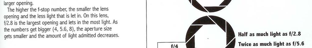


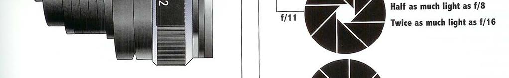
59 Aperture
60 Shutter
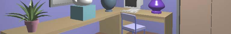
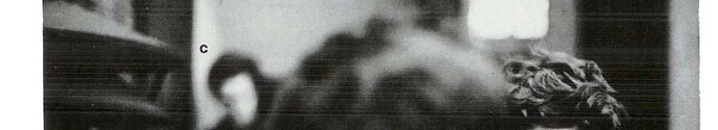
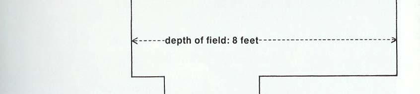
61 Depth of Field Lens focuses on the yellow dot The image of the white dot is a circle of confusion Circles of confusion are actually all out of focus images of subjects Smaller (resp., larger) circles of confusion will be formed if less (resp., more) light can pass through aperture values
62 Depth of Field
63 Aperture controls Depth of Field Changing the aperture size affects the depth of field A smaller aperture increases the range in which the object is approximately in focus But small aperture reduces amount of light need to increase exposure


64 Varying the aperture F/2.0


65 Varying the aperture F/16.0
66 Antialising Super sampling Antialiasing Oversampling rays in each pixel Regular vs. jittered sampling
67 Distributed Ray Tracing Stochastic sampling that randomly distribute rays according to the various parameters Monte Carlo evaluation ation of the multiple integrals that occur in an accurate physical description of surface lighting
68 Distributed Ray Tracing Depth of Field Distributing rays over the circle of confusion
69 Distributed Ray Tracing Motion blur Distributing rays over time
70 Halftoning Simulate the look of a continuous tone image with limited colors How to make gray using tiny dots of black ink
71 Halftoning for displaying intensity levels l more than display device capability (clustered-dot ordered dither) intensity n n spatial frequency of pixels or varying dot size 2 Grid n ( above 0 ) + 1 ( 0 ) intensity levels for bilevel display devices symmetrical pixel arrangements are to be avoided multi-level device : increase the number of intensity level spatial resolution vs. # of intensity it level l tradeoff


72 Texture Mapping Mapping techniques add realism and interest to computer graphics images. Texture mapping applies a pattern of color to an object - umbrella, background, beach ball, beach blanket. Bump mapping alters the surface of an object so that it appears rough, dented d or pitted -sand


 ( x w, yw, zw )")
73 Texture Mapping Texture scanning surface Texture parametrization Object projection Screen space space space Viewing transform T ( u, v ) ( x w, yw, zw ) ( xs, ys) Inverse mapping
74 Non-Parametric Texture Mapping Gives cookie-cutter effect Texture size and orientation fixed, not tied to the size and orientation of the polygon
75 Parametric Texture Mapping Separate texture space and screen space. Texture the polygon as before, but in texture space. Deform the textured polygon into screen space. t v u s
 1. take the four pixel corner points 2. invert the object to screen space transformation 3.")
76 Parametric Texture Mapping Two major difficulties i : inventing i a suitable surfaces; parameterization and antialiasing Use inverse mapping : find pre-image of the current pixel in the texture domain (Fig ) 1. take the four pixel corner points 2. invert the object to screen space transformation 3. invert the surface parameterization Object size decreases pre-image of a pixel in texture space increases : need anti-aliasing aliasing
77 Aliasing and Antialiasing pre-image pixel with pixel w/o anti-aliasing anti-aliasing pixel center


78 Texture Filtering Technique Method I: Brute Force Just sum Method II: Mip Maps a sequence of textures prefiltered at multiple resolutions Lance Willims, 83 stands for multum in parvo, that is many things in a small place makes distant objects look better R G R G R G B B B


 T ( ua, vb ) T (")
79 Texture Filtering i Technique Method III: Summed Area Tables Frank Crow, 1984 Keep sum of everything below and to the left Uses four table lookup Requires more memory Can give excessively blurry textures (u,v) vb va = T ( ub, vb ) T ( ua, vb ) T ( ub, va ) + T ( ua, va ) ua ub
80 Texture Filtering Technique Method IV: Stochastic Sampling Gives noisy images, unless enough samples are taken An extremely simple and robust technique Poisson Completely random Add points at random until area is full. Uniform distribution: some neighboring samples close together, some distant
81 Texture Filtering i Technique Poisson Disc Poisson distribution, with minimum-distance constraint between samples Add points at random, removing again if they are too close to any previous points Very even-looking distribution Jittered Start with regular grid of samples Perturb each sample slightly in a random direction More clumpy or granular in appearance
82 Compositing Composite different images possibly rendered using different techniques into one image Overlay where not zero The first image is overlayed onto the second one where the second image is not black Alpha blending The blending of two colors based on a transparency value. Each pixel of both images contains an alpha value of the image opacity.
83 Compositing Chroma-keying real time video operation overlay when not a predetermined color method e.g., the weather man in front of a flat blue wall
Illumination and Shading
 llumination and Shading llumination and Shading Given: scene specification (object positions, optical properties of the surface, viewer position, viewing direction, ) Find: intensity for each pixel viewer
Illumination Models and Surface-Rendering Methods. Chapter 10
 Illumination Models and Surface-Rendering Methods Chapter 10 Illumination and Surface- Rendering Given scene specifications object positions, optical properties of the surface, viewer position, viewing
Illumination and Shading
 Illumination and Shading Illumination (Lighting)! Model the interaction of light with surface points to determine their final color and brightness! The illumination can be computed either at vertices or
CS5620 Intro to Computer Graphics
 So Far wireframe hidden surfaces Next step 1 2 Light! Need to understand: How lighting works Types of lights Types of surfaces How shading works Shading algorithms What s Missing? Lighting vs. Shading
Illumination Models & Shading
 Illumination Models & Shading Lighting vs. Shading Lighting Interaction between materials and light sources Physics Shading Determining the color of a pixel Computer Graphics ZBuffer(Scene) PutColor(x,y,Col(P));
CPSC 314 LIGHTING AND SHADING
 CPSC 314 LIGHTING AND SHADING UGRAD.CS.UBC.CA/~CS314 slide credits: Mikhail Bessmeltsev et al 1 THE RENDERING PIPELINE Vertices and attributes Vertex Shader Modelview transform Per-vertex attributes Vertex
Computer Graphics. Shading. Based on slides by Dianna Xu, Bryn Mawr College
 Computer Graphics Shading Based on slides by Dianna Xu, Bryn Mawr College Image Synthesis and Shading Perception of 3D Objects Displays almost always 2 dimensional. Depth cues needed to restore the third
Lighting and Shading
 Lighting and Shading Today: Local Illumination Solving the rendering equation is too expensive First do local illumination Then hack in reflections and shadows Local Shading: Notation light intensity in,
w Foley, Section16.1 Reading
 Shading w Foley, Section16.1 Reading Introduction So far, we ve talked exclusively about geometry. w What is the shape of an object? w How do I place it in a virtual 3D space? w How do I know which pixels
CEng 477 Introduction to Computer Graphics Fall
 Illumination Models and Surface-Rendering Methods CEng 477 Introduction to Computer Graphics Fall 2007 2008 Illumination Models and Surface Rendering Methods In order to achieve realism in computer generated
Comp 410/510 Computer Graphics. Spring Shading
 Comp 410/510 Computer Graphics Spring 2017 Shading Why we need shading Suppose we build a model of a sphere using many polygons and then color it using a fixed color. We get something like But we rather
Local Illumination. CMPT 361 Introduction to Computer Graphics Torsten Möller. Machiraju/Zhang/Möller
 Local Illumination CMPT 361 Introduction to Computer Graphics Torsten Möller Graphics Pipeline Hardware Modelling Transform Visibility Illumination + Shading Perception, Interaction Color Texture/ Realism
Recollection. Models Pixels. Model transformation Viewport transformation Clipping Rasterization Texturing + Lights & shadows
 Recollection Models Pixels Model transformation Viewport transformation Clipping Rasterization Texturing + Lights & shadows Can be computed in different stages 1 So far we came to Geometry model 3 Surface
Topic 9: Lighting & Reflection models. Lighting & reflection The Phong reflection model diffuse component ambient component specular component
 Topic 9: Lighting & Reflection models Lighting & reflection The Phong reflection model diffuse component ambient component specular component Spot the differences Terminology Illumination The transport
Introduction to Computer Graphics 7. Shading
 Introduction to Computer Graphics 7. Shading National Chiao Tung Univ, Taiwan By: I-Chen Lin, Assistant Professor Textbook: Hearn and Baker, Computer Graphics, 3rd Ed., Prentice Hall Ref: E.Angel, Interactive
Virtual Reality for Human Computer Interaction
 Virtual Reality for Human Computer Interaction Appearance: Lighting Representation of Light and Color Do we need to represent all I! to represent a color C(I)? No we can approximate using a three-color
I have a meeting with Peter Lee and Bob Cosgrove on Wednesday to discuss the future of the cluster. Computer Graphics
 Announcements Assignment 4 will be out later today Problem Set 3 is due today or tomorrow by 9am in my mail box (4 th floor NSH) How are the machines working out? I have a meeting with Peter Lee and Bob
Topic 9: Lighting & Reflection models 9/10/2016. Spot the differences. Terminology. Two Components of Illumination. Ambient Light Source
 Topic 9: Lighting & Reflection models Lighting & reflection The Phong reflection model diffuse component ambient component specular component Spot the differences Terminology Illumination The transport
Computer Graphics. Illumination Models and Surface-Rendering Methods. Somsak Walairacht, Computer Engineering, KMITL
 Computer Graphics Chapter 10 llumination Models and Surface-Rendering Methods Somsak Walairacht, Computer Engineering, KMTL Outline Light Sources Surface Lighting Effects Basic llumination Models Polygon
CSCI 4620/8626. Computer Graphics Illumination Models and Surface Rendering Methods (Chapter 17)
") CSCI 4620/8626 Computer Graphics Illumination Models and Surface Rendering Methods (Chapter 17) Last update: 2016-04-19 Realism! Realistic displays of a scene use! Perspective projections of objects! Application
CSCI 4620/8626 Computer Graphics Illumination Models and Surface Rendering Methods (Chapter 17) Last update: 2016-04-19 Realism! Realistic displays of a scene use! Perspective projections of objects! Application
Illumination Model. The governing principles for computing the. Apply the lighting model at a set of points across the entire surface.
 Illumination and Shading Illumination (Lighting) Model the interaction of light with surface points to determine their final color and brightness OpenGL computes illumination at vertices illumination Shading
Shading I Computer Graphics I, Fall 2008
 Shading I 1 Objectives Learn to shade objects ==> images appear threedimensional Introduce types of light-material interactions Build simple reflection model Phong model Can be used with real time graphics
Announcements. Written Assignment 2 out (due March 8) Computer Graphics
 Computer Graphics") Announcements Written Assignment 2 out (due March 8) 1 Advanced Ray Tracing (Recursive) Ray Tracing Antialiasing Motion Blur Distribution Ray Tracing Ray Tracing and Radiosity Assumptions Simple shading
Announcements Written Assignment 2 out (due March 8) 1 Advanced Ray Tracing (Recursive) Ray Tracing Antialiasing Motion Blur Distribution Ray Tracing Ray Tracing and Radiosity Assumptions Simple shading
Topic 12: Texture Mapping. Motivation Sources of texture Texture coordinates Bump mapping, mip-mapping & env mapping
 Topic 12: Texture Mapping Motivation Sources of texture Texture coordinates Bump mapping, mip-mapping & env mapping Texture sources: Photographs Texture sources: Procedural Texture sources: Solid textures
Reflection and Shading
 Reflection and Shading R. J. Renka Department of Computer Science & Engineering University of North Texas 10/19/2015 Light Sources Realistic rendering requires that we model the interaction between light
Illumination and Shading
 Illumination and Shading Illumination (Lighting) Model the interaction of light with surface points to determine their final color and brightness OpenGL computes illumination at vertices illumination Shading
CS 325 Computer Graphics
 CS 325 Computer Graphics 04 / 02 / 2012 Instructor: Michael Eckmann Today s Topics Questions? Comments? Illumination modelling Ambient, Diffuse, Specular Reflection Surface Rendering / Shading models Flat
Sung-Eui Yoon ( 윤성의 )
") CS380: Computer Graphics Ray Tracing Sung-Eui Yoon ( 윤성의 ) Course URL: http://sglab.kaist.ac.kr/~sungeui/cg/ Class Objectives Understand overall algorithm of recursive ray tracing Ray generations Intersection
CS380: Computer Graphics Ray Tracing Sung-Eui Yoon ( 윤성의 ) Course URL: http://sglab.kaist.ac.kr/~sungeui/cg/ Class Objectives Understand overall algorithm of recursive ray tracing Ray generations Intersection
EECS 487: Interactive Computer Graphics
 Ray Tracing EECS 487: Interactive Computer Graphics Lecture 29: Distributed Ray Tracing Introduction and context ray casting Recursive ray tracing shadows reflection refraction Ray tracing implementation
CS770/870 Spring 2017 Color and Shading
 Preview CS770/870 Spring 2017 Color and Shading Related material Cunningham: Ch 5 Hill and Kelley: Ch. 8 Angel 5e: 6.1-6.8 Angel 6e: 5.1-5.5 Making the scene more realistic Color models representing the
Visual cues to 3D geometry. Light Reflection and Advanced Shading. Shading. Recognizing materials. size (perspective) occlusion shading
 occlusion shading") Visual cues to 3D geometry Light Reflection and Advanced Shading size (perspective) occlusion shading CS 4620 Lecture 17 1 2 Shading Recognizing materials Variation in observed color across an object strongly
Visual cues to 3D geometry Light Reflection and Advanced Shading size (perspective) occlusion shading CS 4620 Lecture 17 1 2 Shading Recognizing materials Variation in observed color across an object strongly
Topic 11: Texture Mapping 11/13/2017. Texture sources: Solid textures. Texture sources: Synthesized
 Topic 11: Texture Mapping Motivation Sources of texture Texture coordinates Bump mapping, mip mapping & env mapping Texture sources: Photographs Texture sources: Procedural Texture sources: Solid textures
Chapter 10. Surface-Rendering Methods. Somsak Walairacht, Computer Engineering, KMITL
 Computer Graphics Chapter 10 llumination Models and Surface-Rendering Methods Somsak Walairacht, Computer Engineering, KMTL 1 Outline Light Sources Surface Lighting Effects Basic llumination Models Polygon
Computer Graphics. Illumination and Shading
 () Illumination and Shading Dr. Ayman Eldeib Lighting So given a 3-D triangle and a 3-D viewpoint, we can set the right pixels But what color should those pixels be? If we re attempting to create a realistic
surface: reflectance transparency, opacity, translucency orientation illumination: location intensity wavelength point-source, diffuse source
 walters@buffalo.edu CSE 480/580 Lecture 18 Slide 1 Illumination and Shading Light reflected from nonluminous objects depends on: surface: reflectance transparency, opacity, translucency orientation illumination:
Topic 11: Texture Mapping 10/21/2015. Photographs. Solid textures. Procedural
 Topic 11: Texture Mapping Motivation Sources of texture Texture coordinates Bump mapping, mip mapping & env mapping Topic 11: Photographs Texture Mapping Motivation Sources of texture Texture coordinates
Illumination & Shading
 Illumination & Shading Goals Introduce the types of light-material interactions Build a simple reflection model---the Phong model--- that can be used with real time graphics hardware Why we need Illumination
Ray-Tracing. Misha Kazhdan
 Ray-Tracing Misha Kazhdan Ray-Tracing In graphics, we often represent the surface of a 3D shape by a set of triangles. Goal: Ray-Tracing Take a collection of triangles representing a 3D scene and render
So far, we have considered only local models of illumination; they only account for incident light coming directly from the light sources.
 11 11.1 Basics So far, we have considered only local models of illumination; they only account for incident light coming directly from the light sources. Global models include incident light that arrives
Today. Global illumination. Shading. Interactive applications. Rendering pipeline. Computergrafik. Shading Introduction Local shading models
 Computergrafik Matthias Zwicker Universität Bern Herbst 2009 Today Introduction Local shading models Light sources strategies Compute interaction of light with surfaces Requires simulation of physics Global
OpenGl Pipeline. triangles, lines, points, images. Per-vertex ops. Primitive assembly. Texturing. Rasterization. Per-fragment ops.
 OpenGl Pipeline Individual Vertices Transformed Vertices Commands Processor Per-vertex ops Primitive assembly triangles, lines, points, images Primitives Fragments Rasterization Texturing Per-fragment
Shading. Why we need shading. Scattering. Shading. Objectives
 Shading Why we need shading Objectives Learn to shade objects so their images appear three-dimensional Suppose we build a model of a sphere using many polygons and color it with glcolor. We get something
COMP371 COMPUTER GRAPHICS
 COMP371 COMPUTER GRAPHICS SESSION 15 RAY TRACING 1 Announcements Programming Assignment 3 out today - overview @ end of the class Ray Tracing 2 Lecture Overview Review of last class Ray Tracing 3 Local
Illumination & Shading: Part 1
 Illumination & Shading: Part 1 Light Sources Empirical Illumination Shading Local vs Global Illumination Lecture 10 Comp 236 Spring 2005 Computer Graphics Jargon: Illumination Models Illumination - the
Lighting and Reflectance COS 426
 ighting and Reflectance COS 426 Ray Casting R2mage *RayCast(R3Scene *scene, int width, int height) { R2mage *image = new R2mage(width, height); for (int i = 0; i < width; i++) { for (int j = 0; j < height;
Shading. Brian Curless CSE 557 Autumn 2017
 Shading Brian Curless CSE 557 Autumn 2017 1 Reading Optional: Angel and Shreiner: chapter 5. Marschner and Shirley: chapter 10, chapter 17. Further reading: OpenGL red book, chapter 5. 2 Basic 3D graphics
Visualisatie BMT. Rendering. Arjan Kok
 Visualisatie BMT Rendering Arjan Kok a.j.f.kok@tue.nl 1 Lecture overview Color Rendering Illumination 2 Visualization pipeline Raw Data Data Enrichment/Enhancement Derived Data Visualization Mapping Abstract
Computer Graphics. Lecture 13. Global Illumination 1: Ray Tracing and Radiosity. Taku Komura
 Computer Graphics Lecture 13 Global Illumination 1: Ray Tracing and Radiosity Taku Komura 1 Rendering techniques Can be classified as Local Illumination techniques Global Illumination techniques Local
Lecture 15: Shading-I. CITS3003 Graphics & Animation
 Lecture 15: Shading-I CITS3003 Graphics & Animation E. Angel and D. Shreiner: Interactive Computer Graphics 6E Addison-Wesley 2012 Objectives Learn that with appropriate shading so objects appear as threedimensional
Reading. Shading. An abundance of photons. Introduction. Required: Angel , 6.5, Optional: Angel 6.4 OpenGL red book, chapter 5.
 Reading Required: Angel 6.1-6.3, 6.5, 6.7-6.8 Optional: Shading Angel 6.4 OpenGL red book, chapter 5. 1 2 Introduction An abundance of photons So far, we ve talked exclusively about geometry. Properly
Today. Global illumination. Shading. Interactive applications. Rendering pipeline. Computergrafik. Shading Introduction Local shading models
 Computergrafik Thomas Buchberger, Matthias Zwicker Universität Bern Herbst 2008 Today Introduction Local shading models Light sources strategies Compute interaction of light with surfaces Requires simulation
Lighting and Shading Computer Graphics I Lecture 7. Light Sources Phong Illumination Model Normal Vectors [Angel, Ch
 15-462 Computer Graphics I Lecture 7 Lighting and Shading February 12, 2002 Frank Pfenning Carnegie Mellon University http://www.cs.cmu.edu/~fp/courses/graphics/ Light Sources Phong Illumination Model
University of Victoria CSC 305 Shading. Brian Wyvill 2016
 University of Victoria CSC 305 Shading Brian Wyvill 2016 The illuminating Hemisphere Energy and Intensity Energy is the intensity integrated over the solid angle through which it acts. Intensity is not
ECS 175 COMPUTER GRAPHICS. Ken Joy.! Winter 2014
 ECS 175 COMPUTER GRAPHICS Ken Joy Winter 2014 Shading To be able to model shading, we simplify Uniform Media no scattering of light Opaque Objects No Interreflection Point Light Sources RGB Color (eliminating
Lighting Models. CS116B Chris Pollett Mar 21, 2004.
 Lighting Models CS116B Chris Pollett Mar 21, 2004. Outline Overview Light Sources Surface Lighting Effect Basic Illumination Models Overview An illumination model (lighting model) is used to calculate
Illumination. Courtesy of Adam Finkelstein, Princeton University
 llumination Courtesy of Adam Finkelstein, Princeton University Ray Casting mage RayCast(Camera camera, Scene scene, int width, int height) { mage image = new mage(width, height); for (int i = 0; i < width;
Rendering: Reality. Eye acts as pinhole camera. Photons from light hit objects
 Basic Ray Tracing Rendering: Reality Eye acts as pinhole camera Photons from light hit objects Rendering: Reality Eye acts as pinhole camera Photons from light hit objects Rendering: Reality Eye acts as
Distribution Ray-Tracing. Programação 3D Simulação e Jogos
 Distribution Ray-Tracing Programação 3D Simulação e Jogos Bibliography K. Suffern; Ray Tracing from the Ground Up, http://www.raytracegroundup.com Chapter 4, 5 for Anti-Aliasing Chapter 6 for Disc Sampling
Ray Tracing. CSCI 420 Computer Graphics Lecture 15. Ray Casting Shadow Rays Reflection and Transmission [Ch ]
![Ray Tracing. CSCI 420 Computer Graphics Lecture 15. Ray Casting Shadow Rays Reflection and Transmission [Ch ]](/thumbs/78/78594982.jpg "Ray Tracing. CSCI 420 Computer Graphics Lecture 15. Ray Casting Shadow Rays Reflection and Transmission [Ch ]") CSCI 420 Computer Graphics Lecture 15 Ray Tracing Ray Casting Shadow Rays Reflection and Transmission [Ch. 13.2-13.3] Jernej Barbic University of Southern California 1 Local Illumination Object illuminations
CSCI 420 Computer Graphics Lecture 15 Ray Tracing Ray Casting Shadow Rays Reflection and Transmission [Ch. 13.2-13.3] Jernej Barbic University of Southern California 1 Local Illumination Object illuminations
Illumination and Shading
 Illumination and Shading Computer Graphics COMP 770 (236) Spring 2007 Instructor: Brandon Lloyd 2/14/07 1 From last time Texture mapping overview notation wrapping Perspective-correct interpolation Texture
Computer Graphics. Lecture 10. Global Illumination 1: Ray Tracing and Radiosity. Taku Komura 12/03/15
 Computer Graphics Lecture 10 Global Illumination 1: Ray Tracing and Radiosity Taku Komura 1 Rendering techniques Can be classified as Local Illumination techniques Global Illumination techniques Local
Rendering. Illumination Model. Wireframe rendering simple, ambiguous Color filling flat without any 3D information
 llumination Model Wireframe rendering simple, ambiguous Color filling flat without any 3D information Requires modeling interaction of light with the object/surface to have a different color (shade in
WHY WE NEED SHADING. Suppose we build a model of a sphere using many polygons and color it with glcolor. We get something like.
 LIGHTING 1 OUTLINE Learn to light/shade objects so their images appear three-dimensional Introduce the types of light-material interactions Build a simple reflection model---the Phong model--- that can
Specular reflection. Lighting II. Snell s Law. Refraction at boundary of media
 Specular reflection Lighting II CS 465 Lecture 19 Smooth surfaces of pure materials have ideal specular reflection (said this before) Metals (conductors) and dielectrics (insulators) behave differently
CSE 167: Introduction to Computer Graphics Lecture #6: Lights. Jürgen P. Schulze, Ph.D. University of California, San Diego Fall Quarter 2016
 CSE 167: Introduction to Computer Graphics Lecture #6: Lights Jürgen P. Schulze, Ph.D. University of California, San Diego Fall Quarter 2016 Announcements Thursday in class: midterm #1 Closed book Material
Problem Set 4 Part 1 CMSC 427 Distributed: Thursday, November 1, 2007 Due: Tuesday, November 20, 2007
 Problem Set 4 Part 1 CMSC 427 Distributed: Thursday, November 1, 2007 Due: Tuesday, November 20, 2007 Programming For this assignment you will write a simple ray tracer. It will be written in C++ without
9. Illumination and Shading
 9. Illumination and Shading Approaches for visual realism: - Remove hidden surfaces - Shade visible surfaces and reproduce shadows - Reproduce surface properties Texture Degree of transparency Roughness,
Lets assume each object has a defined colour. Hence our illumination model is looks unrealistic.
 Shading Models There are two main types of rendering that we cover, polygon rendering ray tracing Polygon rendering is used to apply illumination models to polygons, whereas ray tracing applies to arbitrary
CS580: Ray Tracing. Sung-Eui Yoon ( 윤성의 ) Course URL:
 Course URL:") CS580: Ray Tracing Sung-Eui Yoon ( 윤성의 ) Course URL: http://sglab.kaist.ac.kr/~sungeui/gcg/ Recursive Ray Casting Gained popularity in when Turner Whitted (1980) recognized that recursive ray casting could
CS580: Ray Tracing Sung-Eui Yoon ( 윤성의 ) Course URL: http://sglab.kaist.ac.kr/~sungeui/gcg/ Recursive Ray Casting Gained popularity in when Turner Whitted (1980) recognized that recursive ray casting could
Lighting. Figure 10.1
 We have learned to build three-dimensional graphical models and to display them. However, if you render one of our models, you might be disappointed to see images that look flat and thus fail to show the
Reading. Shading. Introduction. An abundance of photons. Required: Angel , Optional: OpenGL red book, chapter 5.
 Reading Required: Angel 6.1-6.5, 6.7-6.8 Optional: Shading OpenGL red book, chapter 5. 1 2 Introduction So far, we ve talked exclusively about geometry. What is the shape of an obect? How do I place it
Photorealism: Ray Tracing
 Photorealism: Ray Tracing Reading Assignment: Chapter 13 Local vs. Global Illumination Local Illumination depends on local object and light sources only Global Illumination at a point can depend on any
03 RENDERING PART TWO
 03 RENDERING PART TWO WHAT WE HAVE SO FAR: GEOMETRY AFTER TRANSFORMATION AND SOME BASIC CLIPPING / CULLING TEXTURES AND MAPPING MATERIAL VISUALLY DISTINGUISHES 2 OBJECTS WITH IDENTICAL GEOMETRY FOR NOW,
CS130 : Computer Graphics Lecture 8: Lighting and Shading. Tamar Shinar Computer Science & Engineering UC Riverside
 CS130 : Computer Graphics Lecture 8: Lighting and Shading Tamar Shinar Computer Science & Engineering UC Riverside Why we need shading Suppose we build a model of a sphere using many polygons and color
Computer Graphics I Lecture 11
 15-462 Computer Graphics I Lecture 11 Midterm Review Assignment 3 Movie Midterm Review Midterm Preview February 26, 2002 Frank Pfenning Carnegie Mellon University http://www.cs.cmu.edu/~fp/courses/graphics/
Today s class. Simple shadows Shading Lighting in OpenGL. Informationsteknologi. Wednesday, November 21, 2007 Computer Graphics - Class 10 1
 Today s class Simple shadows Shading Lighting in OpenGL Wednesday, November 21, 27 Computer Graphics - Class 1 1 Simple shadows Simple shadows can be gotten by using projection matrices Consider a light
Computer Graphics. Ray Tracing. Based on slides by Dianna Xu, Bryn Mawr College
 Computer Graphics Ray Tracing Based on slides by Dianna Xu, Bryn Mawr College Ray Tracing Example Created by Anto Matkovic Ray Tracing Example Ray Tracing Example Ray Tracing Most light rays do not reach
CMSC427 Shading Intro. Credit: slides from Dr. Zwicker
 CMSC427 Shading Intro Credit: slides from Dr. Zwicker 2 Today Shading Introduction Radiometry & BRDFs Local shading models Light sources Shading strategies Shading Compute interaction of light with surfaces
Shading. Reading. Pinhole camera. Basic 3D graphics. Brian Curless CSE 557 Fall Required: Shirley, Chapter 10
 Reading Required: Shirley, Chapter 10 Shading Brian Curless CSE 557 Fall 2014 1 2 Basic 3D graphics With affine matrices, we can now transform virtual 3D objects in their local coordinate systems into
Computer Graphics (CS 4731) Lecture 16: Lighting, Shading and Materials (Part 1)
 Lecture 16: Lighting, Shading and Materials (Part 1)") Computer Graphics (CS 4731) Lecture 16: Lighting, Shading and Materials (Part 1) Prof Emmanuel Agu Computer Science Dept. Worcester Polytechnic Institute (WPI) Why do we need Lighting & shading? Sphere
Computer Graphics (CS 4731) Lecture 16: Lighting, Shading and Materials (Part 1) Prof Emmanuel Agu Computer Science Dept. Worcester Polytechnic Institute (WPI) Why do we need Lighting & shading? Sphere
Computer Graphics (CS 543) Lecture 7b: Intro to lighting, Shading and Materials + Phong Lighting Model
 Lecture 7b: Intro to lighting, Shading and Materials + Phong Lighting Model") Computer Graphics (CS 543) Lecture 7b: Intro to lighting, Shading and Materials + Phong Lighting Model Prof Emmanuel Agu Computer Science Dept. Worcester Polytechnic Institute (WPI) Why do we need Lighting
Computer Graphics (CS 543) Lecture 7b: Intro to lighting, Shading and Materials + Phong Lighting Model Prof Emmanuel Agu Computer Science Dept. Worcester Polytechnic Institute (WPI) Why do we need Lighting
CENG 477 Introduction to Computer Graphics. Ray Tracing: Shading
 CENG 477 Introduction to Computer Graphics Ray Tracing: Shading Last Week Until now we learned: How to create the primary rays from the given camera and image plane parameters How to intersect these rays
CS354 Computer Graphics Ray Tracing. Qixing Huang Januray 24th 2017
 CS354 Computer Graphics Ray Tracing Qixing Huang Januray 24th 2017 Graphics Pipeline Elements of rendering Object Light Material Camera Geometric optics Modern theories of light treat it as both a wave
Three-Dimensional Graphics V. Guoying Zhao 1 / 55
 Computer Graphics Three-Dimensional Graphics V Guoying Zhao 1 / 55 Shading Guoying Zhao 2 / 55 Objectives Learn to shade objects so their images appear three-dimensional Introduce the types of light-material
Introduction to Computer Graphics. Farhana Bandukwala, PhD Lecture 14: Light Interacting with Surfaces
 Introduction to Computer Graphics Farhana Bandukwala, PhD Lecture 14: Light Interacting with Surfaces Outline Computational tools Reflection models Polygon shading Computation tools Surface normals Vector
CS452/552; EE465/505. Intro to Lighting
 CS452/552; EE465/505 Intro to Lighting 2-10 15 Outline! Projection Normalization! Introduction to Lighting (and Shading) Read: Angel Chapter 5., sections 5.4-5.7 Parallel Projections Chapter 6, sections
Ø Sampling Theory" Ø Fourier Analysis Ø Anti-aliasing Ø Supersampling Strategies" Ø The Hall illumination model. Ø Original ray tracing paper
 CS 431/636 Advanced Rendering Techniques Ø Dr. David Breen Ø Korman 105D Ø Wednesday 6PM 8:50PM Presentation 6 5/16/12 Questions from ast Time? Ø Sampling Theory" Ø Fourier Analysis Ø Anti-aliasing Ø Supersampling
Computer Vision Systems. Viewing Systems Projections Illuminations Rendering Culling and Clipping Implementations
 Computer Vision Systems Viewing Systems Projections Illuminations Rendering Culling and Clipping Implementations Viewing Systems Viewing Transformation Projective Transformation 2D Computer Graphics Devices
Shading. Brian Curless CSE 457 Spring 2017
 Shading Brian Curless CSE 457 Spring 2017 1 Reading Optional: Angel and Shreiner: chapter 5. Marschner and Shirley: chapter 10, chapter 17. Further reading: OpenGL red book, chapter 5. 2 Basic 3D graphics
Overview. Shading. Shading. Why we need shading. Shading Light-material interactions Phong model Shading polygons Shading in OpenGL
 Overview Shading Shading Light-material interactions Phong model Shading polygons Shading in OpenGL Why we need shading Suppose we build a model of a sphere using many polygons and color it with glcolor.
Objectives. Introduce Phong model Introduce modified Phong model Consider computation of required vectors Discuss polygonal shading.
 Shading II 1 Objectives Introduce Phong model Introduce modified Phong model Consider computation of required vectors Discuss polygonal shading Flat Smooth Gouraud 2 Phong Lighting Model A simple model
Simple Lighting/Illumination Models
 Simple Lighting/Illumination Models Scene rendered using direct lighting only Photograph Scene rendered using a physically-based global illumination model with manual tuning of colors (Frederic Drago and
Orthogonal Projection Matrices. Angel and Shreiner: Interactive Computer Graphics 7E Addison-Wesley 2015
 Orthogonal Projection Matrices 1 Objectives Derive the projection matrices used for standard orthogonal projections Introduce oblique projections Introduce projection normalization 2 Normalization Rather
Surface Rendering Methods
 Surface Rendering Methods 6 th Week, 2008 Sun-Jeong Kim Polygon Rendering Methods Determining the surface intensity at every projected pixel position using an illumination model Light-material interactions
Introduction Ray tracing basics Advanced topics (shading) Advanced topics (geometry) Graphics 2010/2011, 4th quarter. Lecture 11: Ray tracing
 Advanced topics (geometry) Graphics 2010/2011, 4th quarter. Lecture 11: Ray tracing") Lecture 11 Ray tracing Introduction Projection vs. ray tracing Projection Ray tracing Rendering Projection vs. ray tracing Projection Ray tracing Basic methods for image generation Major areas of computer
Lecture 11 Ray tracing Introduction Projection vs. ray tracing Projection Ray tracing Rendering Projection vs. ray tracing Projection Ray tracing Basic methods for image generation Major areas of computer
Homework #2. Shading, Ray Tracing, and Texture Mapping
 Computer Graphics Prof. Brian Curless CSE 457 Spring 2000 Homework #2 Shading, Ray Tracing, and Texture Mapping Prepared by: Doug Johnson, Maya Widyasari, and Brian Curless Assigned: Monday, May 8, 2000
Computer Graphics. Lecture 14 Bump-mapping, Global Illumination (1)
") Computer Graphics Lecture 14 Bump-mapping, Global Illumination (1) Today - Bump mapping - Displacement mapping - Global Illumination Radiosity Bump Mapping - A method to increase the realism of 3D objects
Computer Graphics Lecture 14 Bump-mapping, Global Illumination (1) Today - Bump mapping - Displacement mapping - Global Illumination Radiosity Bump Mapping - A method to increase the realism of 3D objects
Lighting. To do. Course Outline. This Lecture. Continue to work on ray programming assignment Start thinking about final project
 To do Continue to work on ray programming assignment Start thinking about final project Lighting Course Outline 3D Graphics Pipeline Modeling (Creating 3D Geometry) Mesh; modeling; sampling; Interaction
Ray Tracing: Special Topics CSCI 4239/5239 Advanced Computer Graphics Spring 2018
 Ray Tracing: Special Topics CSCI 4239/5239 Advanced Computer Graphics Spring 2018 Theoretical foundations Ray Tracing from the Ground Up Chapters 13-15 Bidirectional Reflectance Distribution Function BRDF
Computer Graphics (CS 543) Lecture 8a: Per-Vertex lighting, Shading and Per-Fragment lighting
 Lecture 8a: Per-Vertex lighting, Shading and Per-Fragment lighting") Computer Graphics (CS 543) Lecture 8a: Per-Vertex lighting, Shading and Per-Fragment lighting Prof Emmanuel Agu Computer Science Dept. Worcester Polytechnic Institute (WPI) Computation of Vectors To calculate
Computer Graphics (CS 543) Lecture 8a: Per-Vertex lighting, Shading and Per-Fragment lighting Prof Emmanuel Agu Computer Science Dept. Worcester Polytechnic Institute (WPI) Computation of Vectors To calculate