Geeetech Rostock mini G2 & G2s pro Quick Starter Manual
|
|
|
- Jayson Powers
- 5 years ago
- Views:
Transcription
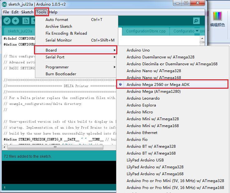
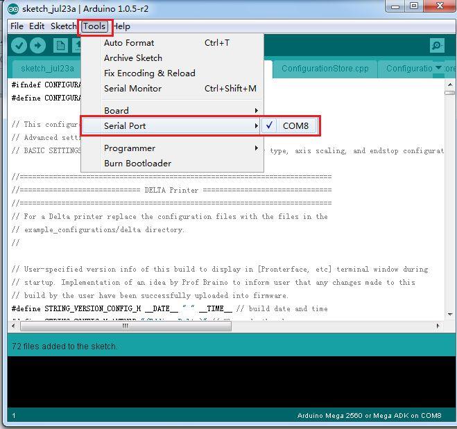
1 Geeetech Rostock mini G2 & G2s pro Quick Starter Manual Please DO NOT rush to start your first printing after assembly, as this is a DIY kit, some parameters of the printer may be different from each other, you need to modify the firmware according the the real situation of your printer. You are advised to read through the whole set-up instructions step by step to get a whole picture of what you will be doing and stick to our instructions before you start with your printer. Do not skip any details. 1 How to modify and upload firmware. In the following set-up process, you will need to modify and upload the firmware by yourself, so, first of all, let s start with the firmware compiling and uploading process. 1. Download the firmware here: Firmware for Delta Rostock mini G2 &G2s pro 2. Connect GT2560 to your PC with a USB cable,install FTDI drive. Usually it will install automatically. If not you need to install manually. download the FTDI driver here. 3. If there is nothing wrong with the hardware of board, you can find COM port in device manager. But every computer has different COM watchword, you need check by yourself. 4. Unzip the firmware, drag all the files into Arduino IDE.(I use Arduino1.0.5), choose Board\Arduino Mega or Mega2560,and selects ATmega2560(Mega2560) as default Processor. The order cannot be wrong. Selects the COM port you find in the device manager.
2
3
4 4 Most of the code you need to modify is in Configuration.h. More details on this later. Find the value you need to compile according to your printer. ( we will elaborate which part of setting you need to change later one by one). Upon compiling, you can upload the firmware to your control board. Simply click and to upload. ( Note: You need to disconnect the printer to Repetier Host before uploading).
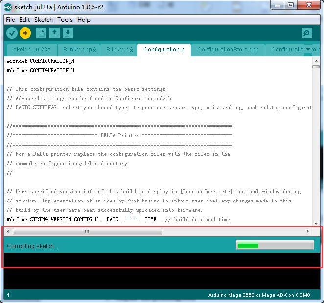
5 Compiling
6 Uploading
7 Upload successfully 2 Printer preparing 1. Bed leveling Put a level meter on the bed when adjusting the 3 screws of the bed to check if it is level.
, and tighten the screw till the cube rightly fill gap between the bed and the base plate.")
8 Or you can use the such a cube use a reference height about 10mm to make sure that each top of each bed mounting point is the same after tightening the wing nuts. Simply place a 10mm cube next to the bed (not under!), and tighten the screw till the cube rightly fill gap between the bed and the base plate. Take out the cube and repeat for the other two mounts.


9 * To protect the bed and the nozzle from crashing, please attach a piece of tape on the bed.

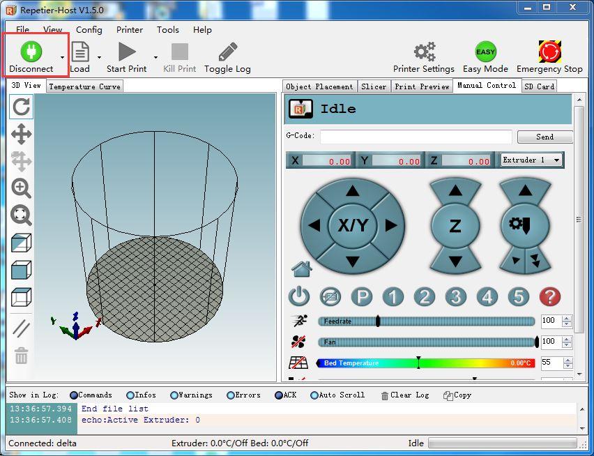
10 3 Printer setting Step1. Connect the USB to your Rostock mini G2 or G2s and power it up. You can see the LED lights and fan come to life, you may be able to hear the motors idling. Step 2. Open Repetier Host and ensure that you have a valid port selected for communications. To do this, simply click Printer Settings in the upper right-hand corner to bring up the printer settings menu. If you don t know what the parameters mean, just hover your mouse over the item, the explanatory note will prompt up. As shown below:

11 Step 3. Choose the Connection menu to select the COM6 port and the Baud rate Click OK to continue.

12 If you can not find the COM port, you can check the device manager to see which port it is). If you still cannot find the port, please re -install your USB driver here. Step4 set the printing speed. And un-check the disable the motors after job/kill.

13 Step5. Set the number and the offset of the extruders (offset only need for duan extruder printer),choose the nozzle size and different colors for each.
14
 and set the following parameters Home X: 0 Home Y: 0 Home Z: Max Printer Radius: 100mm Printable height: 200mm ( this")
15 Step6 Choose printer shape. This is very important. Choose printer type as Rostock Printer (circular shape) and set the following parameters Home X: 0 Home Y: 0 Home Z: Max Printer Radius: 100mm Printable height: 200mm ( this is the corresponding height in the firmware, remember to modify this each time after you change the height in the firmware)
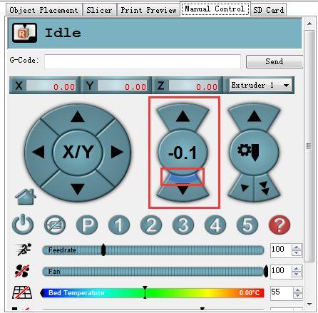
16 Step7. Write the script 1,2,3,4,5 We will use this script as shortcuts later to move the print head to the corresponding point. For each point, keep the Z as 2. For G2 or G2pro: 1 (0, 0, 2) 2 (0,50, 2) 3 (43.3, -25, 2) 4 (-43.3,-25, 2) For G2s or G2s pro: 1 (0, 0, 2) 2 (0,63, 2) 3 (43.3,-2, 2) 4 (-43.3,-2, 2) So we can set the following script.
17 Code G2 or G2pro G2s or G2s pro Script1: G0 X0 Y0 Z2 G0 X0 Y0 Z2 Script2: G0 X0 Y50 Z2 G0 X0 Y63 Z2 Script3: G0 X43.3 Y-25 Z2 G0 X43.3 Y-2 Z2 Script4: G 0 X-43.3 Y-25 Z2 G 0 X-43.3 Y-2 Z2 Apart from the above 4 script, we need to add the fifth code to keep the print head staying in the air and will not creep down the rods. Script 5: G0 X0 Y0 Z180 M84 S0 When you click the script icon, the print head will move to the corresponding test point as shown in the following picture.

18 Write the script 1,2,3,4,5. Here we take the G2 & G2 pro as example. Script 1: G0 X0 Y0 Z2
19
20 Script 2: G0 X0 Y50 Z2
21 Script 3: G0 X43.3 Y-25 Z2
22 Script 4: G0 X-43.3 Y-25 Z2

23 Script 5: G0 X0 Y0 Z180 M84 S0 Note: here we can add M84 S0 to stop the motors from creeping down the rods when hanging in the air.
24 Step8. Remember to name the printer as delta or as you like, next time you open the Repetier Host, just choose the name of the printer, you don t have to set the above parameters again. Step9. Hit "connect" in the upper left-hand corner. You should see the details of the connection in the console window in the bottom section of the screen. If it is
25
26 4 Homing the printer Homing is the first and foremost hing you need to test. To home the printer, you can check if the three axis of the printer move in the same direction,if not, there will be crack for the spider and the carriage. Before homing, you need to follow the next steps. 1.Go to printer setting> printer. Set the travel feed rate and the Z axis feed rate as 300 mm/min. (Even though we have set the speed as slow as possible for you, you still need to adjust the feed rate. ) 2. Hook up the probe with your hand, we are not testing the auto-leveling function right now. So, just leave it alone.

27 3. Move the extruder head to the middle and be ready for emergency stop. You can click the emergency stop icon on the Repetier host or shut the power supply directly.
28 Click Homing icon, you will see the three carriages move upwards till the bolt on the carriage hit the endstop. If the three axis move in the different directions,such as one moves downwards, please check the direction setting in the firmware. E.g. If Y moves in the revers way, find the following code in configuration.h of the firmware, and change true to false. Re-upload the firmware and home again.(remember to disconnect the printer to the Repetier Host.) // Invert the stepper direction. Change (or reverse the motor connector) if an axis goes the wrong way. #define INVERT_X_DIR true // DELTA does not invert #define INVERT_Y_DIR true #define INVERT_Z_DIR true #define INVERT_E0_DIR false #define INVERT_E1_DIR true
, we can set the initial height of the Z axis now, but this value may not be the final height.")
29 #define INVERT_E2_DIR false #define INVERT_E3_DIR false 5 Define the initial Z axis height If the printer can home normally, the three axis move in the same directions(up), we can set the initial height of the Z axis now, but this value may not be the final height. ( For the G2s and G2s pro, the height is on the base of the hotend 1.)

30 1. Homing the printer and move the print head down using manual control. 2. When the Z axis reaches (0,0). You can see there is a big gap between the nozzle and the bed, about 10mm. 3. Change the height of Z axis into 210 in the firmware. And upload it to the board. // Manual homing switch locations: // For deltabots this means top and center of the Cartesian print volume. #ifdef MANUAL_HOME_POSITIONS #define MANUAL_X_HOME_POS 0 #define MANUAL_Y_HOME_POS 0 #define MANUAL_Z_HOME_POS 210 // For delta: Distance between nozzle and print surface after homing.

31 #endif 2 Upon uploading, change the corresponding setting in the Repetier Host and connect.
32 4.Use manual control to move the Z axis down to the building platform till the nozzle just touches the bed. When moving the Z axis, please slow it down. Move 0.1mm per click.
33
34 5. Read the coordinates of the Z axis when the nozzle just touches the bed. E.g. if it is (0,0,4), then the Z axis height is 210-4=206 If it is (0,0,5) the height is 210-5=205. (*210 is height we just set in the firmware. 4 is the Z coordinate we read) 6. Open the firmware in IDE, locate the following code in IDE //Manual homing switch locations: #define MANUAL_HOME_POSITIONS // MANUAL_*_HOME_POS below will be used // For deltabots this means top and center of the Cartesian print volume. #define MANUAL_X_HOME_POS 0 #define MANUAL_Y_HOME_POS 0 #define MANUAL_Z_HOME_POS 210// For delta: Distance between nozzle and print surface after homing. Then you can change the 210 into the height you got (e.g.205 or 206 ) in the firmware and upload it. ( Disconnect the printer first) Upon uploading the firmware, you need to change the printing setting in the Repetier host. 7. Choose printer shape. This is very important. Choose printer type as Rostock Printer(circular shape) Home X: 0 Home Y: 0 Home Z: Max Printer Radius: 100mm Printable height: 205mm (* the corresponding height you put in the firmware)
35 6 Reconfirm the Z axis height Here, we are not measuring the height, but to adjust the printer to make the height at 205mm. That means the following adjusting is based on the the Z axis height of 205mm. Step1. Homing the printer. Step2. Tighten the screw trigger for each endstop, make sure they reach out as long as possible.

36 Adjust the screw on these 3 carriages. Step3.Using G-code command to send the print head to the test points and observe the distance between the nozzle and the print surface separately for the test point 2,3,4. Click 2 on the manual control manual. The print head will move to the corresponding point.
37 When it stopped, use manual control to move the Z axis down to the building platform till the nozzle just touches the bed. When moving the Z axis, please slow it down. Move 0.1mm per click. When the nozzle just touches the bed, read the Z coordinate. If the nozzle touches the bed at the height of 2mm, but not 0 mm, you need to unscrew the bolts on the Z axis carriage. (Test point 2 is near the Z axis). If the print head has reached to 0mm, but not touched the bed, you need to screw the bolts tightly. Repeat the steps for point 3 and 4. You may need to adjust again and again till the Z coordinates are 0 for the three point when they touch the bed. At this step, we are trying to adjust the distance between the nozzle and the print surface to keep the center point and its around point in one plain, that is to say, we need to make sure that when the nozzle touches the bed, whichever point it is, the Z
38 Coordinate value should be the same, or almost the same. You are required to operate again and again till you get a satisfied result. Step 4. If the 3 points touch the bed at 0mm height. We can make sure that the peripheral points are in one plane. Now we need to check the center point. Click script 1 to send the print head to center point. Then use manual control to move the Z axis down to the building platform. *If the nozzle touches the center point at the height of 2mm, but not 0 mm, that means the bed is a convex surface, you should reduce the DELTA_RADIUS from 1 to 0 for example. *If the print head has reached to 0mm, but hasn t touched the bed, that means the bed is a concave surface, you should increase the DELTA_RADIUS from 1 to 2 for example.
 #define DELTA_RADIUS (DELTA_SMOOTH_ROD_OFFSET-DELTA_EFFECTOR_OFFSET-DELTA_CARR IAGE_OFFSET+1) You may have to adjust this for many times to keep the center point and its around point in one")
39 Find the following code in the firmware and upload again after modifying. (For each 1.0 unit increase or reduce of the DELTA_RADIUS, the z printing volume will increase or reduce 0.2 unit) #define DELTA_RADIUS (DELTA_SMOOTH_ROD_OFFSET-DELTA_EFFECTOR_OFFSET-DELTA_CARR IAGE_OFFSET+1) You may have to adjust this for many times to keep the center point and its around point in one plane. (Be patient please) After the above adjusting, we can almost confirm the printing volume, the height of

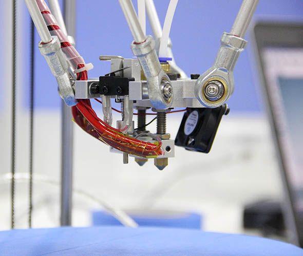
40 the Z axis in other words. That is 205mm as we set in the firmware. If you want to make it more accurate, you can test again refer to the steps in 9.5 Define the initial Z axis height. When the height of the Z axis is determined, we have win half the battle. 7 Hotend leveling This step is exclusive for the dual extruder model. As the above adjusting is only based on the hotend 1, now, we need to level the two hotend. You can adjust the M6 nut as the arrows show. Loose the nut, you can screw the barral to make the second nozzle flush with the first one. ( DO NOT adjust the nut near the heating block or it will cause oozing if you loos it.).


41 8 Slic3r configuration After the above setting, we can go on with the slicer setting. 1. Set the bed shape. In the latest version of Slic3r,V1.2.7, you can set the bed shape, this is very important when printing with your delta Rostock mini. go to general manual, click set button, choose circular and fill in the diameter of the printer bed.
42

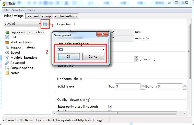
43 if your slic3r is not the latest version, you can update or download it here, unzip the file and drag them into the directory of your previous slic3r directory. do please delete the old version. Restart your Repetier and continue. 2. Load config files. Step 1. Download the config files here and unzip it. Step 2. Click file>load file and find the file you just download.

44 Click OK to continue. Step 3. Save the three parameters as G2s or G2 (according to your printer and the config file you choose, here i choose G2s.)
45
 confirm the start and end G-code.")
46 2. Confirm the parameters. 1) confirm the start and end G-code. They should be like this.
47 2) confirm the extruder offset. One is 13, another is -13. For G2 and G2 pro, just set the number of the extruder as 1.

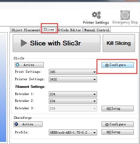
48 We have covered all the important settings. For other parameters you need to learn by yourself with the increasing of your 3D printing experience. 9 Auto-leveling function Though we have added an auto-leveling probe for the Rostock mini, but generally there is no G-code in the sli3er, so we need to add the G29 command to the sli3er. 9.1 Start G29 command in Slic3r. Step1. Click Slicer and configure, waiting for a minute till the slicer window prompt up.

49 Step2. Choose printer setting> Custom G-code. You can see from the start G-code, there is no G29.

50 So you need to add the G29 after G28 to start it. And change Z5 into Z50. Save the current printing setting, click OK to continue.
51 9.2 Check the status of endstop Before going to set up for the auto-leveling, we need to check the status of the endstops. 1. Check the wire connection. the correct connection is as follow:

52 2. Put down the auto-level probe. And make sure the probe is not blocked by the red wires.
53 3. Homing the printer 4. Send M119 command Send the command M119 to verify the endstop first.

54 You can see the following message at the bottom of the Repetier Host. * x_max,y_max,z_max is for the endstop of the three axis: if the endstop is triggered, the feedback is Triggered; If the endstop is not triggered, the feedback is Open. *z_min is for the probe: When probe is put down, the feedback is Open; When probe is hooked up, the feedback is Triggered; If the status is normal, we can go on with the auto-leveling set-up.
55 9.3 Define the Z_PROBE_OFFSET You can calculate the Z_PROBE_OFFSET values with this steps : Step1. Put down the prob. Step2. Homing the printer. Step3. Use manual control to move the print head to the building platform till the prob just touches the bed. When moving the Z axis, please slow it down to 0.1mm or 0.01mm per click. Step4. When you hear the click of the endstop, you can get the coordinate of the prob on the manual control panel. In my case, it is 19, 11, 0.9, you can add it to the following settings. (Note the minus sign) // Offsets to the probe relative to the extruder tip (Hotend - Probe) // X and Y offsets must be integers #define X_PROBE_OFFSET_FROM_EXTRUDER -19 // Probe on: -left +right #define Y_PROBE_OFFSET_FROM_EXTRUDER -11 // Probe on: -front +behind #define Z_PROBE_OFFSET_FROM_EXTRUDER -0.9 // -below (always!) Then modify the Z_PROBE_OFFSET in the firmware and upload again.

56 9.4 Verify the auto-leveling result. Auto-leveling probe is controlled by G29 command. As this is a DIY 3d printer, you may need to help it complete the leveling: 1.You need to put down the auto-leveling probe manually.

57 2.Homing the printer.
58 3.Send G29 command. 4.Auto-leveling probe will probe the the pre-setted probing points. After probing, the print head will raise up a bit and stop in the air.

59 5.Hook up the probe manually.

60 3.Send G1 X0 Y0 command to move the printing head to the center (0,0). 4.Click -Z icon on manual control to move the print head down until it rightly touches the print bed.

61 5. Send M114 command to get the present coordinates.

62 6. If the coordinate is (0,0,0), the auto-leveling is successful.
63 7.If not, you need to modify the #define Z_PROBE_OFFSET_FROM_EXTRUDER -0.9, e.g. Reduce -0.9 to -1.1, and then re-upload the firmware and test again. 8.You may have to test it for more than once, but for the sake of better printing object,please be patient. 9.Once auto-leveling is set up, hook up the probe manually. Then you can print your first prints. Please be patient for the calibration process, if you need helps, please post your problem on our forum, our tech support will help you.
64 9.5 Overall steps for the auto-leveling calibration 1.Manually put down the probe, then send M119 command to check if the Z-min is open. 2.Send G28 command to auto home the printer. 3.Send G29 command to start the auto-leveling. *there might be collisions, please always be ready to cut off the power supply. 4.After sending G29, the printing head will move down, and hit the pre-set probing point, after the probing, the printing head will go up. 5.After the leveling, the printing head will raise up and stop, meaning the leveling is finished. You should have the probe back (as the spring on the probe is a bit tight, to make it easier, you can use your finger to push up the probe) 6.Send G1X0 Y0 command to move the printing head to(0,0). 7.Click -Z icon on manual control to move the print head down until it touches the print bed just enough. Send M114 command to get the present coordinates. If the coordinate is (0,0,0), the auto-leveling is successful. If not, you need to modify the Z_PROBE_OFFSET_FROM_EXTRUDER, e.g. Reduce -1.2 to -1.5, and then re-upload the firmware and test again. 8.You may have to test it for more than once, but for the sake of better printing object,please be patient. 9.Once auto-leveling is set up, Hook up the probe manually. Then you can print your first prints. Please be patient for the calibration process, if you need helps, please post your problem on our forum, our tech support will help you. 10 Printing test So far,the printer is perfectly calibrated, you can start to print with the printer. You are advised to start with some simple models to test the printer with one extruder, with the increase of your experience, you can try to print with dual extruder. Example1. Print with one extruder.

65 1. Load the filament into the pipe from the push-fitting on the extruder. 2. Download this stl.file to test printing. And unzip it. 3. Click printing setting> extruder, change the number of extruder to 1.

66 3.Open slis3r> configuration 4.Click file>load the config.file you download before.
67 5. Save the three parameters as G2 (or anything you like).


68 1.Note the nozzle size below, set it according to your printer, the default kit is 0.4mm. 2. The Extruder offset is x:0, y:0 mm
69 6. Confirm the start and end G-code. They should be like this. We have covered all the important settings. For other parameters you need to learn by yourself with the increasing of your 3D printing experience. 7. Choose the printer and printing settings, filament settings we just saved in the drop-down menu. Here we choose G2.

70 8. Load the stl. File you will print from Object placement > + icon. Direct to the file and open it. 9. Stl. File is successfully loaded.

71 9. You can see it in the preview window. And you can choose different point of view by clicking the cubic on the left.

72 11. Click Slic3r> slice with Slic3r.
73 12 After slicing, you will get the following information about this printing job.
74 13 click G-code Editor to save the file for future use. Or if you have SD card, you can click SD card to save it in the SD card. 14. Click manual control and remove the slash on fan, heated bed and extruder 1.(If you are using extruder 1 now)

75 14. Click start print job to begin. 15. When the temperature reaches the preset value, the printer will start printing, you will see the operation track of the print head as shown below.


76 If you want to stop the printing job, just click pause. Now you can take a rest and wait till the model is built. Example 2. Print with dual extruder. 1. Download the stl. File here and unzip. 2. Click printing setting> extruder, change the number of extruder to 2.

77 3. Choose the printer and printing settings, filament settings we just saved in the drop-down menu. Here we choose G2s.

78 10. Load the stl. File you will print from Object placement > + icon. Direct to the file and open it. Load both files. 9. Stl. File is successfully loaded.


79 Now, you can see the two files are separated. You need to put them together.


80 You need to put them together. Choose the file and click center icon on the top separately. Now the two files are centered and combined together.

81 10.Assign extruder for each file. 11. Click Slic3r> slice with Slic3r. Choose No to continue.

82 12 After slicing, you will get the following information about this printing job.


83 13 click G-code Editor to save the file for future use. Or if you have SD card, you can click SD card to save it in the SD card.

84 14. Click manual control and remove the slash on fan, heated bed and extruder 1.(If you are using extruder 1 now) 16. Click start print job to begin. 17. The printer will home first and wait till the temperature reaches the preset value, the printer will start printing, you will see the operation track of the print head as shown below.

85 The printer is working now. That is all for the geeetech rostock mini G2 and G2s pro. If you have any problem running the printer, please go to our forum for tech support.
Geeetech Aluminum Prusa I3. User Manual
 Geeetech Aluminum Prusa I3 User Manual 1 Safety Instructions Building the printer will require a certain amount of physical dexterity, common sense and a thorough understanding of what you are doing. We
Geeetech Duplicator 5 3D printer. User Manual
 Geeetech Duplicator 5 3D printer User Manual Contents Safety Instructions... 4 1.Software Resources... 5 1.1 Repetier-Host... 5 1.2 Driver... 5 1.3 Arduino IDE... 6 2.Connect the Printer... 6 3.Printer
Documentation version Prusa i3 Rework USER GUIDE REV 1.5. Document Version 1.1.8
 Documentation version 1.1.8 Prusa i3 Rework USER GUIDE REV 1.5 2 INTRODUCTION Target : Prupose a visual guide of the differents steps to build and use a Prusa i3 Rework. Authors of this document : emotion
Geeetech A10. Desktop 3D Printer USER MANUAL
 Geeetech A10 Desktop 3D Printer USER MANUAL Terms Please be advised of the following terms (the Terms ) regarding this User Manual (this Manual ): All information in this Manual is subject to change at
ENJOY Introduction. Software Installation* Hardware. Calibration Settings. Print test. Appendex. Install print S/W Driver Install
 Quick Start Manual 1 ENJOY Introduction C O N T E N T S 6 5 Appendex 4 Print test 3 2 Hardware Calibration Settings Software Installation* Install print S/W Driver Install Hardware Intro Cable installation
USING YOUR BIGBOT. 1/18/2017 V0.1
 USING YOUR BIGBOT www.bigbot-3d.com 1/18/2017 V0.1 FOREWORD: YOUR PRINTER IS REPRAP, WHICH STANDS FOR "REPLICATING RAPID PROTOTYPERS". THIS MEANS IT CAN PRINT THE PARTS THAT ARE CUSTOM FOR THIS MACHINE,
Repetier-Host Documentation
 Repetier-Host Documentation Installation Prerequisites Before you start with the installation, you should check if your computer meets the requirements. Currently available computers should have no problems
Repetier-Host Documentation
 Repetier-Host Documentation Installation Prerequisites Before you start with the installation, you should check if your computer meets the requirements. Currently available computers should have no problems
USER S GUIDE. Documentation Version 1.2.6
 Documentation version 1.2.6 USER S GUIDE INTRODUCTION 2 INTRODUCTION INTRODUCTION / 3 INTRODUCTION Objective: Provide a visual guide of the different steps to set-up and get started using the MicroDelta
A GUIDE TO GETTING STARTED
 Florida Public Library Printing A GUIDE TO GETTING STARTED Prepared for the Florida Public Library by Robert Persing Table of Contents Section-A. Download the software... 3 Section-B. Install the software...
Panowin F1. User Manual
 Panowin F1 User Manual 1 PANOWIN TECHNOLOGIES CO.,LTD. WARNING power outlet. CAUTION: In case of emergency unplug the Panowin F1 from the WARNING: Carefully monitor the Panowin F1 during operation. Do
Repetier-Host Documentation for use with Kora Pro 3D PC
 Repetier-Host Documentation for use with Kora Pro 3D PC Installation Prerequisites Before you start with the installation, you should check if your computer meets the requirements. Currently available
4. Using Cura to Set Up Your Auto-Leveling Probe and Create Your First Print
 4. Using Cura to Set Up Your Auto-Leveling Probe and Create Your First Print Give a short summary. Written By: Printrbot Support INTRODUCTION Outline what you are going to teach someone how to do. 2015
Easy use of Repetier-Host software
 Easy use of Repetier-Host software Examples base on version Repetier-Host 1.06 1. Repetier-Host overview Repetier Host is an easy to use software for 3D printing. The main functions include manual debugging
Technical Support: CUBE USER MANUAL
 CUBE THE DESKTOP 3D PRINTER USER MANUAL 2012-12-05 1 Contents 1 Installing software...3 1.1 Installing Python... 3 1.2 Installing ReplicatorG... 5 2 Pre-print checks...9 2.1 Power up...9 2.2 Connect to
TROUBLESHOOTING GUIDE
 TROUBLESHOOTING GUIDE YOU SHOULDN'T ENCOUNTER many problems when using your Vector 3 printer, however, occasionally things can go wrong. Before contacting Customer Services, please consult this list of
Portabee GO. Mobile 3D Printer. Portabee 3D. Romscraj. Software & Support. Manufacturing & Engineering.
 Portabee GO Mobile 3D Printer Portabee 3D Software & Support http://portabee3d.com support@portabee3d.com Romscraj Manufacturing & Engineering http://romscraj.com contact@romscraj.com A. Software Package
ideamaker Manual
 ideamaker Manual Using ideamaker... 2 Basic information... 2 What is ideamaker?... 2 Where to download ideamaker?... 2 Install ideamaker... 3 Let s Print!... 6 How to use ideamaker?... 23 Interface...
Geeetech A10M. Desktop 3D Printer USER MANUAL
 Geeetech A10M Desktop 3D Printer USER MANUAL Terms Please be advised of the following terms (the Terms ) regarding this User Manual (this Manual ): All information in this Manual is subject to change at
UP! Quick Start Guide
 Personal Portable 3D Printer UP! www.pp3dp.com 1. Assemble Printer Open the box, take out the printer and accessories. Assemble the parts contained in the box as following procedure: 1. Unscrew the M4
SeeMeCNC Guides. Configuring Artemis
 SeeMeCNC Guides Configuring Artemis Configuring your Artemis printer. Connecting it to your network and getting everything dialed in for successful printing. Written By: SeeMeCNC 2018 seemecnc.dozuki.com/
SIMPLEST Bltouch/3Dtouch guide for Creality CR-10/CR- 10s/Ender 2/Ender 3 printers created by Danny Walmsley.
 SIMPLEST Bltouch/3Dtouch guide for Creality CR-10/CR- 10s/Ender 2/Ender 3 printers created by Danny Walmsley. The aim of this guide is to bring auto bed leveling to the masses by making it simple and affordable
SOFTWARE SETUP Pronterface...2 Cura BED CALIBRATION Using Pronterface...11 Using LCD...13
 USER MANUAL TABLE OF CONTENTS SOFTWARE SETUP Pronterface...2 Cura 15.04...3 BED CALIBRATION Using Pronterface...11 Using LCD...13 LOAD/UNLOAD FILAMENT Using LCD (extruder 0 only)...14 Using PRONTERFACE...15
Users Manual of GT2560
 Users Manual of GT2560 Rev A+ Compiler: kris.mao Date: Jan04, 2016 Reviewer: Alina, Le mon Date: Jan04, 2016 Approver: Linda.Fan Date: Jan13, 2016-1 - Contents Copyright Declaration... 3 Technical Support...
USER MANUAL Resolution 0.02mm Speed 300mm/second Software: Wanhao Maker
 1 Duplicator 5S & 5S MINI Desktop 3D Printers USER MANUAL Resolution 0.02mm Speed 300mm/second Software: Wanhao Maker 2014/2015 Wanhao USA 3 Table of Contents Welcome 1 Printer Specifications 2 Unboxing
GEEETECH. Me Creator2 printers contain heated moving parts. Never reach inside the printer while it is in operation or before it has cooled down.
 ME CREATOR 2 SAFETY INSTRUCTION Do read all the instructions and cautionary markings in this manual before operating your Me Creator. Me Creator2 printers contain heated moving parts. Never reach inside
SIMPLEST Bltouch/3Dtouch guide for Creality CR-10/CR- 10s/Ender 2/Ender 3 printers V2 created by Danny Walmsley.
 SIMPLEST Bltouch/3Dtouch guide for Creality CR-10/CR- 10s/Ender 2/Ender 3 printers V2 created by Danny Walmsley. The aim of this guide is to bring auto bed leveling to the masses by making it simple and
USER S GUIDE. Documentation Version 1.0.0
 Documentation version 1.0.0 tt USER S GUIDE INTRODUCTION 2 INTRODUCTION INTRODUCTION / 3 INTRODUCTION Target : Provide a visual guide of the different steps required to use an I3 Metal Motion 3D printer.
Cura - DUET Dual Extrusion Setup
 SeeMeCNC Guides Written By: SeeMeCNC 2018 seemecnc.dozuki.com/ Page 1 of 15 INTRODUCTION Please note that dual extrusion is for advanced users. You should have some advanced knowledge on some G-Code and
SeeMeCNC Guides 2 INTO 1 DUAL FILAMENT FEED ADAPTER INSTALL
 SeeMeCNC Guides 2 INTO 1 DUAL FILAMENT FEED ADAPTER INSTALL These are still in development - Be ready to troubleshoot firmware/software configuration for your setup when purchasing these adapters. Written
Software Manual. Revision 1.3
 Software Manual Revision 1.3 Copyright 2015 by Kudo3D. This material may be distributed only subject to the terms and conditions set forth in the Creative Commons Attribution-NonCommercial-NoDerivatives
M2 3D Printer V4 M2 3D Printer
 M2 3D Printer V4 Contents 2 Important Safeguards 3 Welcome 4 M2 Features 6 Other products included with your printer 7 Set up 9 Slicing.STL or.obj files 10 Maintenance and Support 11 Warranty 12 About
Rich Cattell s Marlin Branch delta calibration for newbies
 Rich Cattell s Marlin Branch delta calibration for newbies Credits Rich Cattell (and contributors) for making this version of auto calibration possible Ira Nana, Minnow blog, and others in google groups
3D SYSTEMS University CubeX 3D Printer
 3D SYSTEMS University CubeX 3D Printer Lesson Leveling the Print Pad and Print Tips, Setting the Z-Gap Revision date: 10/22/13 1 1 2016 年 6 月 14 日 Objectives After completing this lesson you will: Be able
Agenda. Breaking the Ice Physical Setup Walkthrough of REPETREL First Print
 T1 Training Session Agenda Breaking the Ice Physical Setup Walkthrough of REPETREL First Print Breaking the Ice SYSTEM 30M ENGINE Breaking the Ice Protected build environment Slightly larger build area
BASIC MARLIN FIRMWARE CONFIGURATION USER GUIDE FOR THE SMARTRAP 3D PRINTER WITH LCD
 INTRODUCTION: This is a basic user guide on how to verify and/or modify the settings in the Marlin firmware for use with the RepRap SmartRap 3D printer. There are several settings not covered in this manual
USER GUIDE RADDS. December 2014 Version Max3dshop
 USER GUIDE RADDS December 2014 Version 1.01 Max3dshop http://max3dshop.org USER GUIDE ATTRIBUTION-NONCOMMERCIAL-SHAREALIKE 3.0 UNPORTED (CC BY-NC-SA 3.0) 2 1 TABLE OF CONTENTS USER GUIDE 2 Introduction...
Dreamer Series User Manual
 Dreamer Series User Manual Welcome to the world of the Dreamer. To ensure that you have the best possible user experience, it s important that you follow this user manual. Let s get started! In Parts I
ideamaker Manual
 ideamaker Manual www.raise3d.com 1 Using ideamaker... 3 1.1 What is ideamaker?... 3 1.2 Where to download ideamaker?... 3 2 Install ideamaker... 4 3 Let s Print!... 9 3.1 Import.STL files... 9 3.2 Slice
User Guide ADIMLab-gantry 3D printer
 User Guide ADIMLab-gantry 3D printer Version V1.3.2 1 Contents 一 Overview... 4 二 Thanks and Commitment... 6 三 What is 3D Printer... 7 3.1 3D printing steps... 7 3.2 3D Modeling... 7 3.3 Slice output 3D
think big, print huge
 think big, print huge quick start guide Table of Contents a Receiving and uncrating 5 b bed level & z home 11 c Loading filament 19 d SOFTWARE 23 e Setup 23 f preparing a print 26 g printing on gigabot
Instruction Manual. RS 3D Printer
 Instruction Manual RS 3D Printer 1) GENERAL This instruction manual contains important information regarding the installation, operation, maintenance and storage for RS 3D Printer. Please read these instructions
ideamaker Manual
 ideamaker Manual www.raise3d.com 1 Using ideamaker... 3 1.1 What is ideamaker?... 3 1.2 Where to download ideamaker?... 3 2 Install ideamaker... 4 3 Let s Print!... 9 3.1 Import.STL files... 9 3.2 Slice
SeeMeCNC Guides. RAMBo Control Firmware. This guide will show you how to install the firmware on your SeeMeCNC 3D printer.
 SeeMeCNC Guides RAMBo Control Firmware This guide will show you how to install the firmware on your SeeMeCNC 3D printer. Written By: geneb 2018 seemecnc.dozuki.com/ Page 1 of 10 Step 1 Download and Install
MEGATRONICS V3.0 QUICK START GUIDE
 MEGATRONICS V3.0 QUICK START GUIDE Thank you for purchasing the Megatronics v3.0! This small guide will answer the basic questions on how to connect the board to your 3D printer. For more information visit
3D SYSTEMS University Cube 3D Printer
 3D SYSTEMS University Cube 3D Printer Lesson Troubleshooting Machine Issues Revision date: 10/20/13 1 1 2016 年 6 月 14 日 Table of Contents Slide 3 Temperature Errors Slide 5 File Read Errors Slide 7 Filament
M2 3D Printer V4 Rev. D
 M2 3D Printer V4 Rev. D Contents 2 Important Safeguards 3 Welcome 4 M2 Features 6 Other products included with your printer 7 Set up 9 Slicing.STL or.obj files 10 Maintenance and Support 11 Warranty 12
3D Printing Getting Started!
 ARCHITECTURE & LANDSCAPE ARCHITECTURE 3D Printing Getting Started! White filament is free to students for academic use. Where do I buy filament? NORTH DAKOTA STATE UNIVERSITY www.makerbot.com/store www.ultimachine.com/pla
USER GUIDE. RRD Silencioso. August Version 1. User Guide Created Reprapdiscount
 USER GUIDE RRD Silencioso August 2014 Version 1 User Guide Created by @mundsen Reprapdiscount http://reprapdiscount.com USER GUIDE Copyright and third-party information as required ii USER GUIDE Table
DIY PRINTER INSTALLATION AND OPERATION INSTRUCTION
 CTC DIY I3 PRINTER INSTALLATION AND OPERATION INSTRUCTIONS Thank you for buying and using DIY 3D printer produced by CTC Please read the installation and operation instruction carefully before use Company
3d Printing with the Prusa I3 Operation & Printing via a USB Cable
 3d Printing with the Prusa I3 Operation & Printing via a USB Cable Instructions for: Prusa I3 Printer Set-up Slic3r Software Use Pronterface Software Use Prusa I3 - Parts Identification Prusa I3 Printer
SHENZHEN GETECH TECHNOLOGY CO., LTD. Geeetech A10 3D Printer. User Manual (V2.0)
") Geeetech A10 3D Printer User Manual (V2.0) 1 Content 1 Attention... 3 1.1 Safety instruction... 3 1.2 Factory test before delivery... 3 2 Printer display... 4 3 Assembling... 7 3.1 Assembling the main
Geeetech A10 3D Printer User Manual (V2.0) 1 Content 1 Attention... 3 1.1 Safety instruction... 3 1.2 Factory test before delivery... 3 2 Printer display... 4 3 Assembling... 7 3.1 Assembling the main
QUICK START GUIDE. Android or Windows Tablet. 1 Tower PC. Mount the RazorGage to your Own Table. Assembling the RazorGage ST with RazorGage Table
 QUICK START GUIDE Android or Windows Tablet If you have a Tablet Style Interface (PC or Android) then skip this step. 1 Mount monitor and attach legs to control tower using hardware provided and place
Replacing the TFM coupler
 Repair manual Replacing the TFM coupler Instructions The TFM coupler is a key component of the hot end. It allows filament to flow smoothly through it from the Bowden tube and towards the nozzle. The coupler
ZHEJIANG FLASHFORGE 3D TECHNOLOGY CO., LTD. Creator Pro Start-up Guide
 www.ff3dp.com ZHEJIANG FLASHFORGE 3D TECHNOLOGY CO., LTD. Creator Pro Start-up Guide www.ff3dp.com Contents 1 What's Included in the Box? 2 2 Un-boxing 2 3 Initial Hardware Installation 6 4 Software Installation
SHENZHEN GETECH TECHNOLOGY CO LTD. Geeetech A10M 3D Printer. User Manual (v2.0)
") Geeetech A10M 3D Printer User Manual (v2.0) 1 Content 1 Attention... 3 1.1 Safety instructions... 3 1.2 Factory test before delivery... 3 2 Printer display... 4 3 Assembling... 7 3.1 Assembling the main
Geeetech A10M 3D Printer User Manual (v2.0) 1 Content 1 Attention... 3 1.1 Safety instructions... 3 1.2 Factory test before delivery... 3 2 Printer display... 4 3 Assembling... 7 3.1 Assembling the main
Titan Aero Repetier Configuration
 Titan Aero Repetier Configuration Set up your Repetier Firmware to support your new Titan Aero. Written By: Gabe S. 2017 e3d-online.dozuki.com/ Page 1 of 12 Step 1 Download Marlin First things first: you're
Dremel Digilab 3D Slicer Software
 Dremel Digilab 3D Slicer Software Dremel Digilab 3D Slicer prepares your model for 3D printing. For novices, it makes it easy to get great results. For experts, there are over 200 settings to adjust to
Dremel Idea Builder 3D40. Various infill options are available from Simplify 3D software. Varies dependent on the infill and size of your object.
 Guide for Dremel Printing General information The Dremel Idea Builder 3D printer extrudes PLA plastic along a tool path to create layers much like our higher end Dimension. The Dremel however does not
SeeMeCNC Guides. Step 5: Installing the Firmware. This guide will show you how to install the firmware on your Rostock MAX v3 3D printer.
 SeeMeCNC Guides Step 5: Installing the Firmware This guide will show you how to install the firmware on your Rostock MAX v3 3D printer. Written By: geneb 2016 seemecnc.dozuki.com Page 1 of 7 Step 1 Download
1. Home Multiple print head XY calibration manual Downloading the XY calibration file Printing the XY calibration
 Home..................................................................................................... 2 Multiple print head XY calibration manual.........................................................................
Cura (Documentation for version )
") Cura (Documentation for version 15.04.06) Getting Started Installation To start the installation of Cura, download it first. After downloading, open the installer and run the installation wizard to complete
Cura (Documentation for version 15.04.06) Getting Started Installation To start the installation of Cura, download it first. After downloading, open the installer and run the installation wizard to complete
da Vinci Jr.1.0 April 2016 da Vinci Junior 1.0w 3D Printer da Vinci Jr.1.0w Quick Guide HD23F1JW0N1
 da Vinci Junior 1.0w 3D Printer w Quick Guide P 1 Product Overview A: Filament movement area B: Feed module C: Detector D: Extruder E: Filament F: Print bed G G: SD card port (Storage format: FAT32) H:
Certification Guide. Brownsburg Public Library
 Certification Guide Brownsburg Public Library 1 st Maker Space, LLC and Brownsburg Public Library have partnered to increase understanding and access to 3D printing and design technology. Brownsburg Public
PowerSpec Ultra 3D Printer Start-up Guide Table of Contents
 PowerSpec Ultra 3D Printer Start-up Guide Table of Contents 1 What's Included in the Box?...Page 3 2 Un-boxing.Page 4 3 Initial Hardware Installation Page 6 4 Software Instruction.Page 8 5 Filament Page
Advanced Printing. This article will take you to get to know the advanced printing skills.
 Advanced Printing This article will take you to get to know the advanced printing skills. There are two modes are available for users, one is Basic Mode and the other is Expert Mode. Expert Mode grants
Portal Delta Pro 3D printer
 Portal Delta Pro 3D printer User s Manual v1.0 Welcome to the world of 3D printing! Thank you for your purchase of the Mass Portal 3D printer we hope that it will serve you well and even exceed your expectations.
SeeMeCNC Guides. Setting Up Simplify 3D
 SeeMeCNC Guides Setting Up Simplify 3D This guide will walk you through the steps of setting up S3D for slicing and printing on your SeeMeCNC printer. Written By: Jim Carter 2017 seemecnc.dozuki.com Page
JGAURORA 3D PRINTER MODEL: A-4 USER GUIDE
 JGAURORA 3D PRINTER MODEL: A-4 USER GUIDE 1 Contents 1. Preface...3 1.1 Introduction...3 1.2 Safety matters... 3 1.3 Filament requirements...3 1.4 Environmental requirements...3 2. About A-4... 4 2.1 Basic
Written By: Jakub Dolezal
 5. Preflight check Written By: Jakub Dolezal 2018 manual.prusa3d.com/ Page 1 of 17 Step 1 P.I.N.D.A. adjustment (part 1) Ensure the printer is turned off and not plugged in. Note your extruder is slightly
Please carefully read the safety instructions before get started.
 Safety Instructions Please carefully read the safety instructions before get started. ANYCUBIC 3D printer generates high temperature. Do not reach inside of the printer during operation. Allow time for
3-7. Set Materials (Touch Screen) Set Materials (Software) Material Weight adjustment (grams) Current material weight. Increase.
 Set Materials (Software) Material Weight adjustment (grams) Current material weight. Increase.") Set Materials (Touch Screen) 3-7 Decrease Material Weight adjustment (grams) Increase Current material weight Save current settings Stop extrusion and heating Back withdraw material change material extrude
Set Materials (Touch Screen) 3-7 Decrease Material Weight adjustment (grams) Increase Current material weight Save current settings Stop extrusion and heating Back withdraw material change material extrude
USER S GUIDE. Documentation Version 1.2.7
 Documentation version 1.2.7 USER S GUIDE INTRODUCTION 2 INTRODUCTION INTRODUCTION / 3 INTRODUCTION Objective : Provide a visual guide of the different steps to set-up and get started using the MicroDelta
MKS-BASE. MKS BASE is a feature rich all-in-one electronics solution for Reprap and other CNC
 MKS-BASE Overview MKS BASE is a feature rich all-in-one electronics solution for Reprap and other CNC devices. It features an onboard ATmega2560. Its five motor outputs are powered by A4982 stepper drivers.
Makeblock Constructor I 3D Printer Kit. 2. 3D Printer Wiring Guide
 2. 3D Printer Wiring Guide 1 Content 2.1. Parts Required... 3 2.2 preparation... 7 2.2.1 Add heat sinks on the top of stepper motor driver chip... 7 2.2.2 Plug the jumper cap into corresponding position...
Runtime Environment: Relative Humidity: 30%~90% Temperature Ranges : 5 ~35
 Product Data sheet IdeaWerk 3D Printer ENGLISH Runtime Environment: Relative Humidity: 30%~90% Temperature Ranges : 5 ~35 Technical Parameters: 1. Electrical Parameters Power Input: AC 100-240V 47/ 63Hz
- Software KISSlicer Guide - [Z] ArrayZ C4C 3D Printer
![- Software KISSlicer Guide - [Z] ArrayZ C4C 3D Printer](/thumbs/92/108197208.jpg "- Software KISSlicer Guide - [Z] ArrayZ C4C 3D Printer") - Software KISSlicer Guide - ArrayZ C4C 3D Printer Software KISSlicer Guide We are suggesting customers using Kisslicer software as a 3D model slicing program, ArrayZ C4C 3D Printer has many feature is
- Software KISSlicer Guide - ArrayZ C4C 3D Printer Software KISSlicer Guide We are suggesting customers using Kisslicer software as a 3D model slicing program, ArrayZ C4C 3D Printer has many feature is
Product User Manual. IdeaWerk 3D Printer WT150
 Product User Manual IdeaWerk 3D Printer WT150 Contents Contents 1. Unpack and checking... 1 1.1 Check the Machine... 1 1.2 Check the Accessories... 3 2. Brief Introduction... 3 2.1 Precautions and Safety...
English. Quick Guide
 English Quick Guide Specification Product Overview Button and Indicator light Unpacking Accessory Checklist Important Safety Notes Extruder module installation Accessory installation XYZware operation
Removal and Installation8
 8 Screw Types 8-4 Top Cover Assembly 8-5 Left Hand Cover 8-6 Right Hand Cover 8-10 Front Panel Assembly 8-14 Left Rear Cover 8-15 Right Rear Cover 8-16 Extension Cover (60" Model only) 8-17 Media Lever
Manual: ORCABOT XXL PRO2 3D printer
 Manual: ORCABOT XXL PRO2 3D printer Manual: Prodim XXL Pro 2 version 1.0.2 April 2018 www.prodim-systems.com Welcome in the world of 3D printing Thank you for choosing Prodim as your supplier! This manual
da Vinci 1.0 Pro Quick Guide
 US da Vinci 1.0 Pro Quick Guide Product Description Print Parameters Description Support Details Product Model: da Vinci 1.0 Professional da Vinci 1.0 Pro Product Description Product Overview Cartridge
Control Box Setup - PRSalpha
 888-680-4466 ShopBotTools.com Control Box Setup - PRSalpha Copyright 2016 ShopBot Tools, Inc. page 1 Copyright 2016 ShopBot Tools, Inc. page 2 Parts List: Hooking Up a PRSalpha Gantry Tool Powering the
PROGRESS REVIEW 1. Astha Prasad. Team F / ADD_IN. Teammates: Daniel Berman, Nikhil Baheti, Ihsane Debbache ILR #2. October 22 nd, 2015
 PROGRESS REVIEW 1 Astha Prasad Team F / ADD_IN Teammates: Daniel Berman, Nikhil Baheti, Ihsane Debbache ILR #2 October 22 nd, 2015 Individual Progress For this week, my work was mostly focused on two parts:
Overview. Connect the Flight Control Board and Receiver
 Overview This article only describes the methods for connecting the receiver and ESC to the flight control board. You may need to refer to other materials for installation of other devices. If conditions
Math and Science for Sub- Saharan Africa (MS4SSA)
") Sub- Saharan Africa () Project-Based Learning: Introduction 3D Printing / Solid Modeling M.G. Zebaze Kana UNESCO HQ, Paris Introduction 3D Printing / Solid Modeling 1.Background and introduction 2. Overview
Sub- Saharan Africa () Project-Based Learning: Introduction 3D Printing / Solid Modeling M.G. Zebaze Kana UNESCO HQ, Paris Introduction 3D Printing / Solid Modeling 1.Background and introduction 2. Overview
Bondtech QR Installation guide for the BCN3D Sigma
 Bondtech QR Installation guide for the BCN3D Sigma 1 Contents Introduction... 3 List of tool required... 3 Mechanical & Electrical Installation... 4 Adjustment of steps/mm...12 Change Log: 1) Added comment
Design a Simple Fan in 123D Design
 Design a Simple Fan in 123D Design Learn to use 123D Design to make and print this simple fan. 123D Design is a free, powerful, yet simple 3D creation and editing tool. It allows you to design and build
3 Indexer Installation For PRSalpha Tools
 888-680-4466 ShopBotTools.com 3 Indexer Installation For PRSalpha Tools Copyright 2016 ShopBot Tools, Inc. page 1 Copyright 2016 ShopBot Tools, Inc. page 2 Table of Contents General Safety and Precautions...5
Model: 3-Axis High Quality Self-Assembled 3D Printer Kit. Panowin F1
 ESTIMATE No.: Client: Telephone: E-mail: Address: City, State: Contact: Cell-Phone: Fax: Zip Code: Country: Panowin Technologies Co., Ltd. Model: 3-Axis High Quality Self-Assembled 3D Printer Kit Panowin
Replacing the Encoder Strip
 6-1-11. Replacing the Encoder Strip The following describes the procedure for replacing the Encoder Strip. Refer to the diagram below for identifying the parts and their positions. (The numbers shown in
Ender 3 Series 3D Printer Quick Start Guide
 Ender 3 Series 3D Printer Quick Start Guide This guide is for the Ender 3 Series of 3D printers. Select the correct input voltage to match your local mains (220V or 110V) Because of software/hardware upgrades
Introduction. EC2 User Manual with Technical Addendum 1.0 1
 Introduction The EC2 Explorer Experience is a self-serve kiosk that simulates wind and reflective glare conditions. Key features that can aid the associate/customer in making a decision on their sunglass
2014 Simplify3D. Quick Start Guide
 Quick Start Guide Preparation Installing Simplify3D Software 3 The Configuration Assistant 4 The Interface Layout 5 3D Printing Workflow Import Process Settings Preview Print! Import 7 Process Settings
DeltaMaker 3D Printer Getting Started
 DeltaMaker 3D Printer Getting Started Last Updated: December 2014 Table of Contents TABLE OF CONTENTS 2 WELCOME 3 SECTION 1: UNPACKING/SETUP 4 REMOVING THE PRINTER FROM THE BOX 4 INSTALLING THE FILAMENT
Complete Installation manual
 VapoChill TM CPU Cooling System - LightSpeed [AC] TM asetek Inc. Complete Installation manual Date Version Comments 01-04-2004 1.0 1 Installing the VapoChill LightSpeed [AC] TM Preparing the case Step
Next Generation 3D Printer
 Next Generation 3D Printer By Fahad Alahmari, Sebastian Arevalo, Brad Evans, Tomas Garcia, Benjamin Gouveia and Jake Work Team 11 Midpoint Report Document Submitted towards partial fulfillment of the requirements
HDS Series Quick Start Guide.
 Techno-Osai Start Up Sequence HDS Series Quick Turn the Main power switch to the ON Position. 220 volts should have been attached to this switch by an electrician. Power On Button. Computer power ON. The
The following illustration demonstrates what you would see when the print jet nozzles are properly leveled.
 INF Printing Verify the Print Jet Nozzle Level Leveling the print jet nozzles is very important to ensure quality prints especially after replacing a print jet, an extruder assembly or the print pad. The
D300 Professional Desktop 3D Printer
 D300 Professional Desktop 3D Printer - Multiple hotend options - Advanced software - Enclosed chamber - Built to order AUTOMATION READY Automatic calibration Multiple hotend options Controlled chamber