Logic Gates and Boolean Algebra ENT263
|
|
|
- Roger Brown
- 5 years ago
- Views:
Transcription
1 Logic Gates and Boolean Algebra ENT263
2 Logic Gates and Boolean Algebra Now that we understand the concept of binary numbers, we will study ways of describing how systems using binary logic levels make decisions. Boolean algebra is an important tool in describing, analyzing, designing, and implementing digital circuits.
3 Boolean Constants and Variables Boolean algebra allows only two values; 0 and 1. Logic 0 can be: false, off, low, no, open switch. Logic 1 can be: true, on, high, yes, closed switch. Three basic logic operations: OR, AND, and NOT.
4 Truth Tables A truth table describes the relationship between the input and output of a logic circuit. The number of entries corresponds to the number of inputs. For example a 2 input table would have 2 2 = 4 entries. A 3 input table would have 2 3 = 8 entries.
5 Truth Tables Examples of truth tables with 2, 3, and 4 inputs.
6 OR Operation With OR Gates The Boolean expression for the OR operation is X = A + B This is read as x equals A or B. X = 1 when A = 1 or B = 1. Truth table and circuit symbol for a two input OR gate:
7 OR Operation With OR Gates The OR operation is similar to addition but when A = 1 and B = 1, the OR operation produces = 1. In the Boolean expression x=1+1+1=1 We could say in English that x is true (1) when A is true (1) OR B is true (1) OR C is true (1).
8 OR Operation With OR Gates There are many examples of applications where an output function is desired when one of multiple inputs is activated.
9 AND Operations with AND gates The Boolean expression for the AND operation is X = A B This is read as x equals A and B. x = 1 when A = 1 and B = 1. Truth table and circuit symbol for a two input AND gate are shown. Notice the difference between OR and AND gates.
10 Operation With AND Gates The AND operation is similar to multiplication. In the Boolean expression X = A B C X = 1 only when A = 1, B = 1, and C = 1.
11 NOT Operation The Boolean expression for the NOT operation is X = A This is read as: x equals NOT A, or x equals the inverse of A, or x equals the complement of A
12 NOT Operation Truth table, symbol, and sample waveform for the NOT circuit.
13 Describing Logic Circuits Algebraically The three basic Boolean operations (OR, AND, NOT) can describe any logic circuit. If an expression contains both AND and OR gates the AND operation will be performed first, unless there is a parenthesis in the expression.
14 Describing Logic Circuits Algebraically Examples of Boolean expressions for logic circuits:
15 Describing Logic Circuits Algebraically The output of an inverter is equivalent to the input with a bar over it. Input A through an inverter equals A. Examples using inverters.
16 Evaluating Logic Circuit Outputs Rules for evaluating a Boolean expression: Perform all inversions of single terms. Perform all operations within parenthesis. Perform AND operation before an OR operation unless parenthesis indicate otherwise. If an expression has a bar over it, perform the operations inside the expression and then invert the result.
17 Evaluating Logic Circuit Outputs Evaluate Boolean expressions by substituting values and performing the indicated operations: A = 0, B = 1, C = 1, and x = ABC(A + D) = (0 + 1) = (0 + 1) = (1) = = 0 D = 1
18 Evaluating Logic Circuit Outputs Output logic levels can be determined directly from a circuit diagram. The output of each gate is noted until a final output is found.
19 Implementing Circuits From Boolean Expressions It is important to be able to draw a logic circuit from a Boolean expression. The expression x = A B C could be drawn as a three input AND gate. A more complex example such as y = AC + BC + ABC could be drawn as two 2-input AND gates and one 3-input AND gate feeding into a 3-input OR gate. Two of the AND gates have inverted inputs.
20 NOR Gates and NAND Gates Combine basic AND, OR, and NOT operations. The NOR gate is an inverted OR gate. An inversion bubble is placed at the output of the OR gate. The Boolean expression is, x = A + B
21 NOR Gates and NAND Gates The NAND gate is an inverted AND gate. An inversion bubble is placed at the output of the AND gate. The Boolean expression is x = AB
22 NOR Gates and NAND Gates The output of NAND and NOR gates may be found by simply determining the output of an AND or OR gate and inverting it. The truth tables for NOR and NAND gates show the complement of truth tables for OR and AND gates.
23 Universality of NAND and NOR Gates NAND or NOR gates can be used to create the three basic logic expressions (OR, AND, and INVERT) This characteristic provides flexibility and is very useful in logic circuit design.
24 Combinations of NANDs are used to create the three logic functions.
25 combinations of NORs are used to create the three logic functions.

26 The Exclusive OR X = A B

27 The Exclusive NOR X = AB + AB
28 IEEE/ANSI Standard Logic Symbols Compare the IEEE/ANSI symbols to traditional symbols. These symbols are not widely accepted but may appear in some schematics.
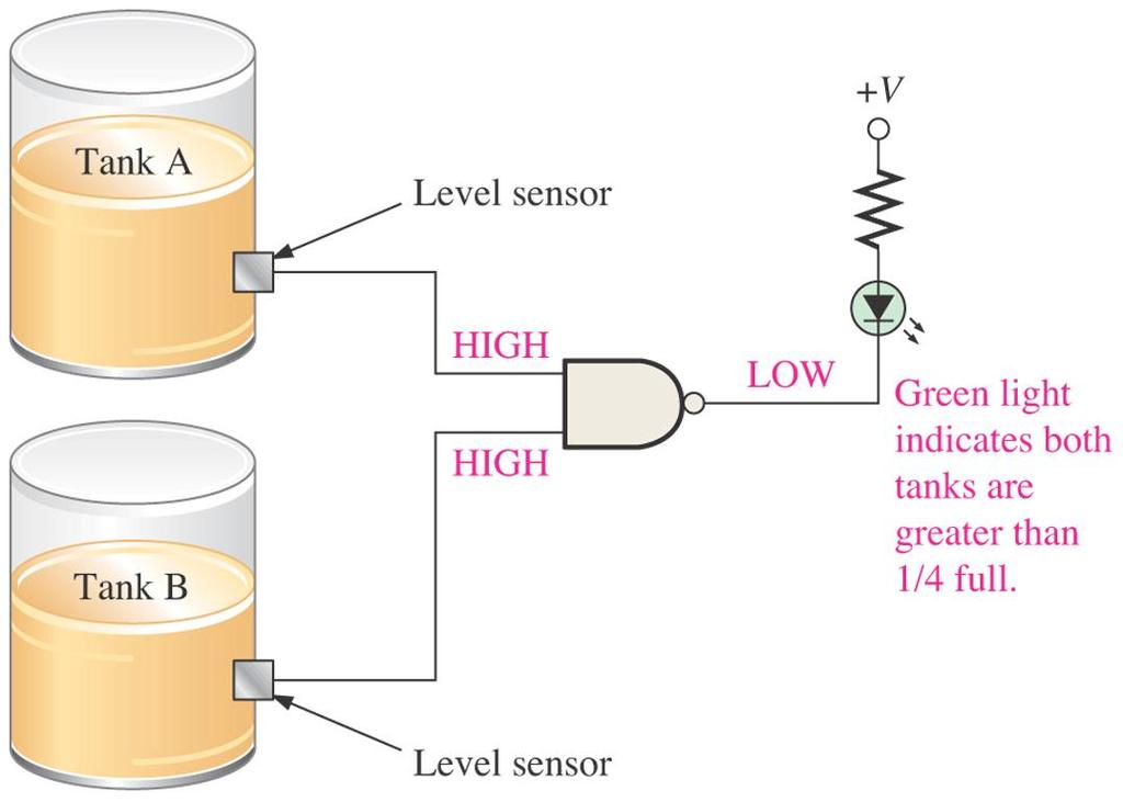
29 Application
30 Application
31 Exercise Output Boolean expressions??? Truth Table???
32 Exercise V1 0V U5A L1 U4A U6A V2 0V U1A Boolean expressions??? V3 0V U4B Truth Table??? L2 V4 0V U2A U3A U6B
33 Summary of Methods to Describe Logic Circuits The three basic logic functions are AND, OR, and NOT. Logic functions allow us to represent a decision process. If it is raining OR it looks like rain I will take an umbrella. If I get paid AND I go to the bank I will have money to spend.
34 Thank You
Assignment (3-6) Boolean Algebra and Logic Simplification - General Questions
 Boolean Algebra and Logic Simplification - General Questions") Assignment (3-6) Boolean Algebra and Logic Simplification - General Questions 1. Convert the following SOP expression to an equivalent POS expression. 2. Determine the values of A, B, C, and D that make
Assignment (3-6) Boolean Algebra and Logic Simplification - General Questions 1. Convert the following SOP expression to an equivalent POS expression. 2. Determine the values of A, B, C, and D that make
Bawar Abid Abdalla. Assistant Lecturer Software Engineering Department Koya University
 Logic Design First Stage Lecture No.5 Boolean Algebra Bawar Abid Abdalla Assistant Lecturer Software Engineering Department Koya University Boolean Operations Laws of Boolean Algebra Rules of Boolean Algebra
Department of Electrical Engineering McGill University ECSE 221 Introduction to Computer Engineering Assignment 2 Combinational Logic
 Department of Electrical Engineering McGill University ECSE 221 Introduction to Computer Engineering Assignment 2 Combinational Logic Question 1: Due October 19 th, 2009 A convenient shorthand for specifying
Experiment 4 Boolean Functions Implementation
 Experiment 4 Boolean Functions Implementation Introduction: Generally you will find that the basic logic functions AND, OR, NAND, NOR, and NOT are not sufficient to implement complex digital logic functions.
that system. weighted value associated with it. numbers. a number. the absence of a signal. MECH 1500 Quiz 2 Review Name: Class: Date:
 Name: Class: Date: MECH 1500 Quiz 2 Review True/False Indicate whether the statement is true or false. 1. The decimal system uses the number 9 as its base. 2. All digital computing devices perform operations
QUESTION BANK FOR TEST
 CSCI 2121 Computer Organization and Assembly Language PRACTICE QUESTION BANK FOR TEST 1 Note: This represents a sample set. Please study all the topics from the lecture notes. Question 1. Multiple Choice
ENGIN 112 Intro to Electrical and Computer Engineering
 ENGIN 2 Intro to Electrical and Computer Engineering Lecture 5 Boolean Algebra Overview Logic functions with s and s Building digital circuitry Truth tables Logic symbols and waveforms Boolean algebra
LSN 4 Boolean Algebra & Logic Simplification. ECT 224 Digital Computer Fundamentals. Department of Engineering Technology
 LSN 4 Boolean Algebra & Logic Simplification Department of Engineering Technology LSN 4 Key Terms Variable: a symbol used to represent a logic quantity Compliment: the inverse of a variable Literal: a
Combinational Circuits Digital Logic (Materials taken primarily from:
 Combinational Circuits Digital Logic (Materials taken primarily from: http://www.facstaff.bucknell.edu/mastascu/elessonshtml/eeindex.html http://www.cs.princeton.edu/~cos126 ) Digital Systems What is a
Combinational Circuits
 Combinational Circuits Combinational circuit consists of an interconnection of logic gates They react to their inputs and produce their outputs by transforming binary information n input binary variables
Introduction to Computer Architecture
 Boolean Operators The Boolean operators AND and OR are binary infix operators (that is, they take two arguments, and the operator appears between them.) A AND B D OR E We will form Boolean Functions of
Ch. 5 : Boolean Algebra &
 Ch. 5 : Boolean Algebra & Reduction elektronik@fisika.ui.ac.id Objectives Should able to: Write Boolean equations for combinational logic applications. Utilize Boolean algebra laws and rules for simplifying
EEE130 Digital Electronics I Lecture #4_1
 EEE130 Digital Electronics I Lecture #4_1 - Boolean Algebra and Logic Simplification - By Dr. Shahrel A. Suandi 4-6 Standard Forms of Boolean Expressions There are two standard forms: Sum-of-products form
Chapter 2 Boolean algebra and Logic Gates
 Chapter 2 Boolean algebra and Logic Gates 2. Introduction In working with logic relations in digital form, we need a set of rules for symbolic manipulation which will enable us to simplify complex expressions
Gate Level Minimization Map Method
 Gate Level Minimization Map Method Complexity of hardware implementation is directly related to the complexity of the algebraic expression Truth table representation of a function is unique Algebraically
Introduction to Boolean logic and Logical Gates
 Introduction to Boolean logic and Logical Gates Institute of Statistics Fall 2014 We saw the importance of the binary number system for data representation in a computer system. We ll see that the construction
EE292: Fundamentals of ECE
 EE292: Fundamentals of ECE Fall 2012 TTh 10:00-11:15 SEB 1242 Lecture 22 121115 http://www.ee.unlv.edu/~b1morris/ee292/ 2 Outline Review Binary Number Representation Binary Arithmetic Combinatorial Logic
DeMorgan's Theorem. George Self. 1 Introduction
 OpenStax-CNX module: m46633 1 DeMorgan's Theorem George Self This work is produced by OpenStax-CNX and licensed under the Creative Commons Attribution License 3.0 Abstract Boolean Algebra is used to mathematically
Chapter 3. Gate-Level Minimization. Outlines
 Chapter 3 Gate-Level Minimization Introduction The Map Method Four-Variable Map Five-Variable Map Outlines Product of Sums Simplification Don t-care Conditions NAND and NOR Implementation Other Two-Level
GC03 Boolean Algebra
 Why study? GC3 Boolean Algebra Computers transfer and process binary representations of data. Binary operations are easily represented and manipulated in Boolean algebra! Digital electronics is binary/boolean
DIGITAL CIRCUIT LOGIC UNIT 7: MULTI-LEVEL GATE CIRCUITS NAND AND NOR GATES
 DIGITAL CIRCUIT LOGIC UNIT 7: MULTI-LEVEL GATE CIRCUITS NAND AND NOR GATES 1 iclicker Question 13 Considering the K-Map, f can be simplified as (2 minutes): A) f = b c + a b c B) f = ab d + a b d AB CD
MULTIMEDIA COLLEGE JALAN GURNEY KIRI KUALA LUMPUR
 STUDENT IDENTIFICATION NO MULTIMEDIA COLLEGE JALAN GURNEY KIRI 54100 KUALA LUMPUR SECOND SEMESTER FINAL EXAMINATION, 2013/2014 SESSION ITC2223 COMPUTER ORGANIZATION & ARCHITECTURE DSEW-E-F 1/13 18 FEBRUARY
Chapter 2. Boolean Expressions:
 Chapter 2 Boolean Expressions: A Boolean expression or a function is an expression which consists of binary variables joined by the Boolean connectives AND and OR along with NOT operation. Any Boolean
Boolean Analysis of Logic Circuits
 Course: B.Sc. Applied Physical Science (Computer Science) Year & Sem.: IInd Year, Sem - IIIrd Subject: Computer Science Paper No.: IX Paper Title: Computer System Architecture Lecture No.: 7 Lecture Title:
the absence of a signal. produce a result at one or more of their outputs. parallel. Y= AB. interconnected. connected. changed.
 Name: Class: Date: MECH 1500 Midterm Review True/False Indicate whether the statement is true or false. 1. Normally, a binary 1 represents the presence of a signal, while a binary 0 represents the absence
Summary. Boolean Addition
 Summary Boolean Addition In Boolean algebra, a variable is a symbol used to represent an action, a condition, or data. A single variable can only have a value of or 0. The complement represents the inverse
1. Mark the correct statement(s)
") 1. Mark the correct statement(s) 1.1 A theorem in Boolean algebra: a) Can easily be proved by e.g. logic induction b) Is a logical statement that is assumed to be true, c) Can be contradicted by another
1. Mark the correct statement(s) 1.1 A theorem in Boolean algebra: a) Can easily be proved by e.g. logic induction b) Is a logical statement that is assumed to be true, c) Can be contradicted by another
2008 The McGraw-Hill Companies, Inc. All rights reserved.
 28 The McGraw-Hill Companies, Inc. All rights reserved. 28 The McGraw-Hill Companies, Inc. All rights reserved. All or Nothing Gate Boolean Expression: A B = Y Truth Table (ee next slide) or AB = Y 28
CS/COE 0447 Example Problems for Exam 2 Spring 2011
 CS/COE 0447 Example Problems for Exam 2 Spring 2011 1) Show the steps to multiply the 4-bit numbers 3 and 5 with the fast shift-add multipler. Use the table below. List the multiplicand (M) and product
Code No: R Set No. 1
 Code No: R059210504 Set No. 1 II B.Tech I Semester Regular Examinations, November 2007 DIGITAL LOGIC DESIGN ( Common to Computer Science & Engineering, Information Technology and Computer Science & Systems
SYNERGY INSTITUTE OF ENGINEERING & TECHNOLOGY,DHENKANAL LECTURE NOTES ON DIGITAL ELECTRONICS CIRCUIT(SUBJECT CODE:PCEC4202)
") Lecture No:5 Boolean Expressions and Definitions Boolean Algebra Boolean Algebra is used to analyze and simplify the digital (logic) circuits. It uses only the binary numbers i.e. 0 and 1. It is also called
Lecture No:5 Boolean Expressions and Definitions Boolean Algebra Boolean Algebra is used to analyze and simplify the digital (logic) circuits. It uses only the binary numbers i.e. 0 and 1. It is also called
EECS150 Homework 2 Solutions Fall ) CLD2 problem 2.2. Page 1 of 15
 CLD2 problem 2.2. Page 1 of 15") 1.) CLD2 problem 2.2 We are allowed to use AND gates, OR gates, and inverters. Note that all of the Boolean expression are already conveniently expressed in terms of AND's, OR's, and inversions. Thus,
1.) CLD2 problem 2.2 We are allowed to use AND gates, OR gates, and inverters. Note that all of the Boolean expression are already conveniently expressed in terms of AND's, OR's, and inversions. Thus,
Gate-Level Minimization
 MEC520 디지털공학 Gate-Level Minimization Jee-Hwan Ryu School of Mechanical Engineering Gate-Level Minimization-The Map Method Truth table is unique Many different algebraic expression Boolean expressions may
Objectives: 1. Design procedure. 2. Fundamental circuits. 1. Design procedure
 Objectives: 1. Design procedure. 2. undamental circuits. 1. Design procedure Design procedure has five steps: o Specification. o ormulation. o Optimization. o Technology mapping. o Verification. Specification:
Code No: R Set No. 1
 Code No: R059210504 Set No. 1 II B.Tech I Semester Supplementary Examinations, February 2007 DIGITAL LOGIC DESIGN ( Common to Computer Science & Engineering, Information Technology and Computer Science
Lecture 3: Binary Subtraction, Switching Algebra, Gates, and Algebraic Expressions
 EE210: Switching Systems Lecture 3: Binary Subtraction, Switching Algebra, Gates, and Algebraic Expressions Prof. YingLi Tian Feb. 5/7, 2019 Department of Electrical Engineering The City College of New
ELCT201: DIGITAL LOGIC DESIGN
 ELCT201: DIGITAL LOGIC DESIGN Dr. Eng. Haitham Omran, haitham.omran@guc.edu.eg Dr. Eng. Wassim Alexan, wassim.joseph@guc.edu.eg Lecture 3 Following the slides of Dr. Ahmed H. Madian ذو الحجة 1438 ه Winter
LAB #1 BASIC DIGITAL CIRCUIT
 LAB #1 BASIC DIGITAL CIRCUIT OBJECTIVES 1. To study the operation of basic logic gates. 2. To build a logic circuit from Boolean expressions. 3. To introduce some basic concepts and laboratory techniques
(Refer Slide Time 3:31)
") Digital Circuits and Systems Prof. S. Srinivasan Department of Electrical Engineering Indian Institute of Technology Madras Lecture - 5 Logic Simplification In the last lecture we talked about logic functions
Digital Circuits and Systems Prof. S. Srinivasan Department of Electrical Engineering Indian Institute of Technology Madras Lecture - 5 Logic Simplification In the last lecture we talked about logic functions
Following the advice of breaking the longest (uppermost) bar first, I'll begin by breaking the bar covering the entire expression as a first step:
 bar first, I'll begin by breaking the bar covering the entire expression as a first step:") DeMorgans Theorems A mathematician named DeMorgan developed a pair of important rules regarding group complementation in Boolean algebra. By group complementation, I'm referring to the complement of a
DeMorgans Theorems A mathematician named DeMorgan developed a pair of important rules regarding group complementation in Boolean algebra. By group complementation, I'm referring to the complement of a
Simplification of Boolean Functions
 COM111 Introduction to Computer Engineering (Fall 2006-2007) NOTES 5 -- page 1 of 5 Introduction Simplification of Boolean Functions You already know one method for simplifying Boolean expressions: Boolean
A B A+B
 ECE 25 Lab 2 One-bit adder Design Introduction The goal of this lab is to design a one-bit adder using programmable logic on the BASYS board. Due to the limitations of the chips we have in stock, we need
Experiment 3: Logic Simplification
 Module: Logic Design Name:... University no:.. Group no:. Lab Partner Name: Mr. Mohamed El-Saied Experiment : Logic Simplification Objective: How to implement and verify the operation of the logical functions
Read this before starting!
 Points missed: Student's Name: Total score: /100 points East Tennessee State University Department of Computer and Information Sciences CSCI 2150 (Tarnoff) Computer Organization TEST 1 for Spring Semester,
Principles of Digital Techniques PDT (17320) Assignment No State advantages of digital system over analog system.
 Assignment No State advantages of digital system over analog system.") Assignment No. 1 1. State advantages of digital system over analog system. 2. Convert following numbers a. (138.56) 10 = (?) 2 = (?) 8 = (?) 16 b. (1110011.011) 2 = (?) 10 = (?) 8 = (?) 16 c. (3004.06)
Assignment No. 1 1. State advantages of digital system over analog system. 2. Convert following numbers a. (138.56) 10 = (?) 2 = (?) 8 = (?) 16 b. (1110011.011) 2 = (?) 10 = (?) 8 = (?) 16 c. (3004.06)
B.Tech II Year I Semester (R13) Regular Examinations December 2014 DIGITAL LOGIC DESIGN
 Regular Examinations December 2014 DIGITAL LOGIC DESIGN") B.Tech II Year I Semester () Regular Examinations December 2014 (Common to IT and CSE) (a) If 1010 2 + 10 2 = X 10, then X is ----- Write the first 9 decimal digits in base 3. (c) What is meant by don
B.Tech II Year I Semester () Regular Examinations December 2014 (Common to IT and CSE) (a) If 1010 2 + 10 2 = X 10, then X is ----- Write the first 9 decimal digits in base 3. (c) What is meant by don
Austin Herring Recitation 002 ECE 200 Project December 4, 2013
 1. Fastest Circuit a. How Design Was Obtained The first step of creating the design was to derive the expressions for S and C out from the given truth tables. This was done using Karnaugh maps. The Karnaugh
Propositional Calculus. Math Foundations of Computer Science
 Propositional Calculus Math Foundations of Computer Science Propositional Calculus Objective: To provide students with the concepts and techniques from propositional calculus so that they can use it to
BOOLEAN ALGEBRA. Logic circuit: 1. From logic circuit to Boolean expression. Derive the Boolean expression for the following circuits.
 COURSE / CODE DIGITAL SYSTEMS FUNDAMENTAL (ECE 421) DIGITAL ELECTRONICS FUNDAMENTAL (ECE 422) BOOLEAN ALGEBRA Boolean Logic Boolean logic is a complete system for logical operations. It is used in countless
Read this before starting!
 Points missed: Student's Name: Total score: /100 points East Tennessee State University Department of Computer and Information Sciences CSCI 2150 (Tarnoff) Computer Organization TEST 1 for Spring Semester,
Simplification of Boolean Functions
 Simplification of Boolean Functions Contents: Why simplification? The Map Method Two, Three, Four and Five variable Maps. Simplification of two, three, four and five variable Boolean function by Map method.
ELCT201: DIGITAL LOGIC DESIGN
 ELCT201: DIGITAL LOGIC DESIGN Dr. Eng. Haitham Omran, haitham.omran@guc.edu.eg Dr. Eng. Wassim Alexan, wassim.joseph@guc.edu.eg Lecture 3 Following the slides of Dr. Ahmed H. Madian محرم 1439 ه Winter
 Get Free notes at Module-I One s Complement: Complement all the bits.i.e. makes all 1s as 0s and all 0s as 1s Two s Complement: One s complement+1 SIGNED BINARY NUMBERS Positive integers (including zero)
Combinational Logic Circuits
 Chapter 3 Combinational Logic Circuits 12 Hours 24 Marks 3.1 Standard representation for logical functions Boolean expressions / logic expressions / logical functions are expressed in terms of logical
1 Discussion. 2 Pre-Lab
 CSE 275 Digital Design Lab Lab 3 Implementation of a Combinational Logic Circuit Penn State Erie, The Behrend College Fall Semester 2007 Number of Lab Periods: 1 1 Discussion The purpose of this lab is
(Refer Slide Time 6:48)
") Digital Circuits and Systems Prof. S. Srinivasan Department of Electrical Engineering Indian Institute of Technology Madras Lecture - 8 Karnaugh Map Minimization using Maxterms We have been taking about
Digital Circuits and Systems Prof. S. Srinivasan Department of Electrical Engineering Indian Institute of Technology Madras Lecture - 8 Karnaugh Map Minimization using Maxterms We have been taking about
COMP combinational logic 1 Jan. 18, 2016
 In lectures 1 and 2, we looked at representations of numbers. For the case of integers, we saw that we could perform addition of two numbers using a binary representation and using the same algorithm that
R10. II B. Tech I Semester, Supplementary Examinations, May
 SET - 1 1. a) Convert the following decimal numbers into an equivalent binary numbers. i) 53.625 ii) 4097.188 iii) 167 iv) 0.4475 b) Add the following numbers using 2 s complement method. i) -48 and +31
Variable, Complement, and Literal are terms used in Boolean Algebra.
 We have met gate logic and combination of gates. Another way of representing gate logic is through Boolean algebra, a way of algebraically representing logic gates. You should have already covered the
LECTURE 4. Logic Design
 LECTURE 4 Logic Design LOGIC DESIGN The language of the machine is binary that is, sequences of 1 s and 0 s. But why? At the hardware level, computers are streams of signals. These signals only have two
UNIT-4 BOOLEAN LOGIC. NOT Operator Operates on single variable. It gives the complement value of variable.
 UNIT-4 BOOLEAN LOGIC Boolean algebra is an algebra that deals with Boolean values((true and FALSE). Everyday we have to make logic decisions: Should I carry the book or not?, Should I watch TV or not?
R07
 www..com www..com SET - 1 II B. Tech I Semester Supplementary Examinations May 2013 SWITCHING THEORY AND LOGIC DESIGN (Com. to EEE, EIE, BME, ECC) Time: 3 hours Max. Marks: 80 Answer any FIVE Questions
Recitation Session 6
 Recitation Session 6 CSE341 Computer Organization University at Buffalo radhakri@buffalo.edu March 11, 2016 CSE341 Computer Organization Recitation Session 6 1/26 Recitation Session Outline 1 Overview
MODULE 5 - COMBINATIONAL LOGIC
 Introduction to Digital Electronics Module 5: Combinational Logic 1 MODULE 5 - COMBINATIONAL LOGIC OVERVIEW: For any given combination of input binary bits or variables, the logic will have a specific
1. Boolean algebra. [6] 2. Constructing a circuit. [4] 3. Number representation [4] 4. Adders [4] 5. ALU [2] 6. Software [4]
![1. Boolean algebra. [6] 2. Constructing a circuit. [4] 3. Number representation [4] 4. Adders [4] 5. ALU [2] 6. Software [4]](/thumbs/93/114163715.jpg "1. Boolean algebra. [6] 2. Constructing a circuit. [4] 3. Number representation [4] 4. Adders [4] 5. ALU [2] 6. Software [4]") Family Name:.......................... Other Names:.......................... ID Number:.......................... ENGR101: Test 4 May 2009 Instructions Time allowed: 45 minutes. There are 45 marks in
Family Name:.......................... Other Names:.......................... ID Number:.......................... ENGR101: Test 4 May 2009 Instructions Time allowed: 45 minutes. There are 45 marks in
2. BOOLEAN ALGEBRA 2.1 INTRODUCTION
 2. BOOLEAN ALGEBRA 2.1 INTRODUCTION In the previous chapter, we introduced binary numbers and binary arithmetic. As you saw in binary arithmetic and in the handling of floating-point numbers, there is
Circuit analysis summary
 Boolean Algebra Circuit analysis summary After finding the circuit inputs and outputs, you can come up with either an expression or a truth table to describe what the circuit does. You can easily convert
NAND. Grade (10) Instructor. Logic Design 1 / 13
 Instructor. Logic Design 1 / 13") Logic Design I Laboratory 02 NAND NOR XOR # Student ID 1 Student Name Grade (10) Instructor signature 2 3 Delivery Date 1 / 13 Objective To find the basic NAND & NOR & XOR gates concept and study on multiple
Logic Design I Laboratory 02 NAND NOR XOR # Student ID 1 Student Name Grade (10) Instructor signature 2 3 Delivery Date 1 / 13 Objective To find the basic NAND & NOR & XOR gates concept and study on multiple
EECS 140/141 Introduction to Digital Logic Design Fall Semester 2016 Exam #1 Date: 3 October 2016
 EECS 4/4 Introduction to Digital Logic Design Fall Semester 26 Exam # Date: 3 October 26 NAME: KUID: General Instructions. This exam is closed-book. You are allowed a non-communicating calculator and one
Code No: R Set No. 1
 Code No: R059210504 Set No. 1 II B.Tech I Semester Regular Examinations, November 2006 DIGITAL LOGIC DESIGN ( Common to Computer Science & Engineering, Information Technology and Computer Science & Systems
Injntu.com Injntu.com Injntu.com R16
 1. a) What are the three methods of obtaining the 2 s complement of a given binary (3M) number? b) What do you mean by K-map? Name it advantages and disadvantages. (3M) c) Distinguish between a half-adder
Programmable Logic Devices (PLDs)
") Programmable Logic Devices (PLDs) 212: Digital Design I, week 13 PLDs basically store binary information in a volatile/nonvolatile device. Data is specified by designer and physically inserted (Programmed)
Programmable Logic Devices (PLDs) 212: Digital Design I, week 13 PLDs basically store binary information in a volatile/nonvolatile device. Data is specified by designer and physically inserted (Programmed)
Logic and Computer Design Fundamentals. Chapter 2 Combinational Logic Circuits. Part 3 Additional Gates and Circuits
 Logic and Computer Design Fundamentals Chapter 2 Combinational Logic Circuits Part 3 Additional Gates and Circuits Charles Kime & Thomas Kaminski 28 Pearson Education, Inc. (Hyperlinks are active in View
Date Performed: Marks Obtained: /10. Group Members (ID):. Experiment # 04. Boolean Expression Simplification and Implementation
:. Experiment # 04. Boolean Expression Simplification and Implementation") Name: Instructor: Engr. Date Performed: Marks Obtained: /10 Group Members (ID):. Checked By: Date: Experiment # 04 Boolean Expression Simplification and Implementation OBJECTIVES: To understand the utilization
Name: Instructor: Engr. Date Performed: Marks Obtained: /10 Group Members (ID):. Checked By: Date: Experiment # 04 Boolean Expression Simplification and Implementation OBJECTIVES: To understand the utilization
CENG 241 Digital Design 1
 CENG 241 Digital Design 1 Lecture 5 Amirali Baniasadi amirali@ece.uvic.ca This Lecture Lab Review of last lecture: Gate-Level Minimization Continue Chapter 3:XOR functions, Hardware Description Language
Digital Techniques. Lecture 1. 1 st Class
 Digital Techniques Lecture 1 1 st Class Digital Techniques Digital Computer and Digital System: Digital computer is a part of digital system, it based on binary system. A block diagram of digital computer
60-265: Winter ANSWERS Exercise 4 Combinational Circuit Design
 60-265: Winter 2010 Computer Architecture I: Digital Design ANSWERS Exercise 4 Combinational Circuit Design Question 1. One-bit Comparator [ 1 mark ] Consider two 1-bit inputs, A and B. If we assume that
Midterm Exam Review. CS 2420 :: Fall 2016 Molly O'Neil
 Midterm Exam Review CS 2420 :: Fall 2016 Molly O'Neil Midterm Exam Thursday, October 20 In class, pencil & paper exam Closed book, closed notes, no cell phones or calculators, clean desk 20% of your final
Chapter 3. Boolean Algebra and Digital Logic
 Chapter 3 Boolean Algebra and Digital Logic Chapter 3 Objectives Understand the relationship between Boolean logic and digital computer circuits. Learn how to design simple logic circuits. Understand how
EECS 140 Laboratory Exercise 5 Prime Number Recognition
 1. Objectives EECS 140 Laboratory Exercise 5 Prime Number Recognition A. Become familiar with a design process B. Practice designing, building, and testing a simple combinational circuit 2. Discussion
Read this before starting!
 Points missed: Student's Name: Total score: /100 points East Tennessee State University Department of Computer and Information Sciences CSCI 2150 (Tarnoff) Computer Organization TEST 1 for Spring Semester,
This podcast will demonstrate a logical approach as to how a computer adds through logical gates.
 This podcast will demonstrate a logical approach as to how a computer adds through logical gates. A computer is a programmable machine that receives input, stores and manipulates data, and provides output
2.6 BOOLEAN FUNCTIONS
 2.6 BOOLEAN FUNCTIONS Binary variables have two values, either 0 or 1. A Boolean function is an expression formed with binary variables, the two binary operators AND and OR, one unary operator NOT, parentheses
Lecture (05) Boolean Algebra and Logic Gates
 Boolean Algebra and Logic Gates") Lecture (05) Boolean Algebra and Logic Gates By: Dr. Ahmed ElShafee ١ Minterms and Maxterms consider two binary variables x and y combined with an AND operation. Since eachv ariable may appear in either
Lecture (05) Boolean Algebra and Logic Gates By: Dr. Ahmed ElShafee ١ Minterms and Maxterms consider two binary variables x and y combined with an AND operation. Since eachv ariable may appear in either
Combinational Devices and Boolean Algebra
 Combinational Devices and Boolean Algebra Silvina Hanono Wachman M.I.T. L02-1 6004.mit.edu Home: Announcements, course staff Course information: Lecture and recitation times and locations Course materials
SIR C.R.REDDY COLLEGE OF ENGINEERING, ELURU DEPARTMENT OF INFORMATION TECHNOLOGY LESSON PLAN
 SIR C.R.REDDY COLLEGE OF ENGINEERING, ELURU DEPARTMENT OF INFORMATION TECHNOLOGY LESSON PLAN SUBJECT: CSE 2.1.6 DIGITAL LOGIC DESIGN CLASS: 2/4 B.Tech., I SEMESTER, A.Y.2017-18 INSTRUCTOR: Sri A.M.K.KANNA
Hours / 100 Marks Seat No.
 17333 13141 3 Hours / 100 Seat No. Instructions (1) All Questions are Compulsory. (2) Answer each next main Question on a new page. (3) Illustrate your answers with neat sketches wherever necessary. (4)
R07. Code No: V0423. II B. Tech II Semester, Supplementary Examinations, April
 SET - 1 II B. Tech II Semester, Supplementary Examinations, April - 2012 SWITCHING THEORY AND LOGIC DESIGN (Electronics and Communications Engineering) Time: 3 hours Max Marks: 80 Answer any FIVE Questions
Gate Level Minimization
 Gate Level Minimization By Dr. M. Hebaishy Digital Logic Design Ch- Simplifying Boolean Equations Example : Y = AB + AB Example 2: = B (A + A) T8 = B () T5 = B T Y = A(AB + ABC) = A (AB ( + C ) ) T8 =
Gate-Level Minimization. BME208 Logic Circuits Yalçın İŞLER
 Gate-Level Minimization BME28 Logic Circuits Yalçın İŞLER islerya@yahoo.com http://me.islerya.com Complexity of Digital Circuits Directly related to the complexity of the algebraic expression we use to
Logic Design: Part 2
 Orange Coast College Business Division Computer Science Department CS 6- Computer Architecture Logic Design: Part 2 Where are we? Number systems Decimal Binary (and related Octal and Hexadecimal) Binary
Binary. Hexadecimal BINARY CODED DECIMAL
 Logical operators Common arithmetic operators, like plus, minus, multiply and divide, works in any number base but the binary number system provides some further operators, called logical operators. Meaning
Objectives: 1- Bolean Algebra. Eng. Ayman Metwali
 Objectives: Chapter 3 : 1- Boolean Algebra Boolean Expressions Boolean Identities Simplification of Boolean Expressions Complements Representing Boolean Functions 2- Logic gates 3- Digital Components 4-
SECTION-A
 M.Sc(CS) ( First Semester) Examination,2013 Digital Electronics Paper: Fifth ------------------------------------------------------------------------------------- SECTION-A I) An electronics circuit/ device
Read this before starting!
 Points missed: Student's Name: Total score: /100 points East Tennessee State University Department of Computer and Information Sciences CSCI 2150 (Tarnoff) Computer Organization TEST 1 for Fall Semester,
Computer Science. Unit-4: Introduction to Boolean Algebra
 Unit-4: Introduction to Boolean Algebra Learning Objective At the end of the chapter students will: Learn Fundamental concepts and basic laws of Boolean algebra. Learn about Boolean expression and will
Chap-2 Boolean Algebra
 Chap-2 Boolean Algebra Contents: My name Outline: My position, contact Basic information theorem and postulate of Boolean Algebra. or project description Boolean Algebra. Canonical and Standard form. Digital
4. Write a sum-of-products representation of the following circuit. Y = (A + B + C) (A + B + C)
 (A + B + C)") COP 273, Winter 26 Exercises 2 - combinational logic Questions. How many boolean functions can be defined on n input variables? 2. Consider the function: Y = (A B) (A C) B (a) Draw a combinational logic
COP 273, Winter 26 Exercises 2 - combinational logic Questions. How many boolean functions can be defined on n input variables? 2. Consider the function: Y = (A B) (A C) B (a) Draw a combinational logic
VALLIAMMAI ENGINEERING COLLEGE. SRM Nagar, Kattankulathur DEPARTMENT OF ELECTRONICS AND COMMUNICATION ENGINEERING EC6302 DIGITAL ELECTRONICS
 VALLIAMMAI ENGINEERING COLLEGE SRM Nagar, Kattankulathur-603 203 DEPARTMENT OF ELECTRONICS AND COMMUNICATION ENGINEERING EC6302 DIGITAL ELECTRONICS YEAR / SEMESTER: II / III ACADEMIC YEAR: 2015-2016 (ODD
Section 001. Read this before starting!
 Points missed: Student's Name: Total score: / points East Tennessee State University Department of Computer and Information Sciences CSCI 25 (Tarnoff) Computer Organization TEST 2 for Fall Semester, 25