SANDMAN Power Management User Manual
|
|
|
- Penelope Hopkins
- 5 years ago
- Views:
Transcription

1 SANDMAN Power Management User Manual
2 Table of Contents Contents 1. Introduction Limitations User Responsibility Theory of Operation Specifications and Characteristics Performance Specifications Electrical Characteristics Absolute Maximum Ratings Mechanical and Pin Assignments Dimensions Recommended Connectors Pin Assignments Hardware Integration Power Input Power Output Power Communication Interface Pin 1 - TX Pin 2 - RX Pin 3 and Pin 9 - Ground Pin 4 - ISP Pin 5 - DIO Pin 6 DIO Pin 7 DIO Pin 8 DIO Communication UART I2C Port Power Status LED Software Interface Basic format Number Formats LRC Checksum Code ACK / NACK Response Input Details Input Summary PING ( 0x00) SET TIME ( 0x01) GET TIME ( 0x02) SET ALARM ( 0x03) GET ALARM ( 0x04) STORE DATA ( 0x05) GET DATA ( 0x06) GOTOSLEEP ( 0x07) EASY SLEEP ( 0x08) ABORT MODE ( 0x09) GENERIC SLEEP ( 0x0A) DATA PACKAGE ( 0x10)... 21
3 CLEAR WAKEUP FLAG ( 0x11) Output Details Output s PING ( 0x00) RESERVED ( 0x01) UNIT TIME ( 0x02) RESERVED ( 0x03) UNIT ALARM ( 0x04) RESERVED ( 0x05) GET DATA ( 0x06) RESERVED ( 0x07) RESERVED ( 0x08) ACK ( 0x21) NACK ( 0x63) Software Reprogramming Software Release Notes Appendix A: Quick Start Example... 28
4 Release Notes Title Sandman Subtitle Sandman User Manual Manual Document number UM3000 Revision Index Date Status / s Initial Release 11/2012 MR Initial release A 3/1/2013 MR Updated input and output messages Errata on stored byte capability noted (max is 1024 bytes vs. 4096) Quickstart example added B 3/22/2013 MR Updated ACK/NACK for better communication standard to X-Monkey Added ABORT message to release Sandman from data storage or playback modes C 12/22/2013 MR Cleanup on some messages. Added Generic Sleep for generic wake up time Only applies to SW version 1.1 (and higher) IMPORTANT DISCLAIMERS This document and the use of any information contained therein, is subject to the acceptance of the Ryan Mechatronics terms and conditions. They can be downloaded from Ryan Mechatronics LLC makes no warranties based on the accuracy or completeness of the contents of this document and reserves the right to make changes to specifications and product descriptions at any time without notice. Ryan Mechatronics LLC assumes no liability for damages or otherwise due to use of the information in this document or application of any device described in this document. Ryan Mechatronics LLC stresses end user compliance with all applicable laws and regulations when using devices of this nature. Use by an end user in violation of any applicable laws is automatic basis for termination of warranty, technical support and future sales. Ryan Mechatronics LLC reserves all rights to this document and the information contained herein. Reproduction, use or disclosure to third parties without express permission is strictly prohibited. Copyright , Ryan Mechatronics LLC
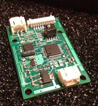
5 1. Introduction The Sandman is a power management and data storage electronic board that allows you to effectively turn electronic hardware off for a specified amount of time, then have it turn back on. During the power down phase, current draw to the Sandman board is approximately 100 microamps. Sandman can control power to systems from 3.3V up to 20V while allowing up to 1.8 amps of current. Up to 1k of data can be stored in nonvolatile memory on Sandman before turning power off, allowing your system to save system status and other information for use after power has returned. The communication interface is via a 3.3V level UART with simple command structure. The Sandman is intended for use in remote sensing applications that require strict power management to operate effectively. 1.1 Limitations The unit, like any IMU / AHRS, can be pushed beyond the limits of its ability to sense any of the measurements it needs to operate correctly. The following list includes results that are known to occur if operation exceeds the limits listed later in this document User Responsibility Accidental programming of an incorrect wake-up can result in a system that goes to sleep and stays asleep. Please be careful and test your system thoroughly before deployment. 1.2 Theory of Operation The Sandman integrates low resistance power circuitry, a low power real time clock unit and a CPU capable of deep power down modes in a single package that allows users to: Control the voltage supply to a separate system Store data to nonvolatile flash Turn off power to another system or the host system with automatic wake up 4
6 2. Specifications and Characteristics Presented in this section are the sensor and system specifications for the Sandman. All parameters specified VDD = 5.0 V and Ta = 25 C unless otherwise noted. 2.1 Performance Specifications Characteristics Conditions Min Typical Max Units Memory Size NVM storage available for user bytes Communication UART characteristics 115,200 baud, 8-N Specifications are subject to change at any time without notice 2.2 Electrical Characteristics Characteristics Conditions Min Typical Max Units Power Supply Voltage V dd V Range Referenced to GND Current, maximum Maximum to load on output A pass thru to load Support circuitry, System operating and awake 4.5 ma normal operation Support circuitry in deep sleep System in deep sleep, load output turned off 105 ua Specifications are subject to change at any time without notice 2.3 Absolute Maximum Ratings Parameter Rating V dd -0.3V to +20V Operating Temperature Range Storage Temperature Range -40 C to +85 C -55 C to +125 C Specifications are subject to change at any time without notice Stresses above those listed under the Absolute Maximum Ratings may cause permanent damage to the device. This is a stress rating only; functional operation of the device at or near these or any other conditions above those indicated in the operational section of this specification is not implied. Exposure to absolute maximum rating conditions for extended periods of time may affect device reliability. 5
(SN) (Digikey P/N: 455-1749-1-ND). There are many mating options for this connector, but an easy method is to purchase pre-crimped / built mating cables.")
7 2.4 Mechanical and Pin Assignments Dimensions All units shown in inches Recommended Connectors Power In / Out The Input and Output power connectors are identical. They are JST connector part S2B-PH-SM4- TB(LF)(SN) (Digikey P/N: ND). There are many mating options for this connector, but an easy method is to purchase pre-crimped / built mating cables. An example of this is Pololu item which is a connector and 14cm wire length. For reference, a picture of this connector is shown here: 6


8 Communications Connector (X1) The communications connector has a set of connections for discrete I/O and communication. This connector is a 9 pin Molex socket. The mating connector for this is Digi-Key part number WM1727- ND, but this is just the connector housing. Pre-crimped wires can be found at Newark, part number For reference, a picture of this connector is shown here: Pin Assignments Table 1 Power In/Out Connector Pin Assignments Pin # Pin I/O Pin Connection Required for Typical Operation? 1 Vin N/A X Or Vout if output connector 2 GND N/A X 7
9 Table 2 Communication (X1) Pin Assignments Pin # Pin I/O Pin Connection Required for Typical Operation? 1 TX O UART com from Sandman 3.3V level 2 RX I X UART com to Sandman 3.3V level 3 GND N/A X Ground 4 ISP I Hold low upon power for reprogramming of unit (not standard) 5 DIO1 I TBD 6 DIO2 I TBD 7 SDA/DIO3 I TBD 8 SCL/DIO4 I TBD 9 GND N/A Ground (redundant to pin 3) 8
10 3. Hardware Integration Presented in this section are selected hardware interface comments to help ease integration of the unit in the end user system. 3.1 Power Input Power The module operates off the input power voltage. On board circuitry operates at 3.3V levels. However, up to 20V may be applied at this connector. The system draws very little power; typically it will require less than 5 ma of supply for operation when not in sleep mode Output Power The module outputs the input power voltage when the unit is programmed to allow this output. When the unit goes to sleep, this output power is turned off. 3.2 Communication Interface The module utilizes the X1 pins to command the unit and receive status. These pins are described here Pin 1 - TX Output data from the module Pin 2 - RX Commands to the module Pin 3 and Pin 9 - Ground Ground pins for signal use Pin 4 - ISP In system programming pin. Pull low upon boot to load new code via UART Pin 5 - DIO1 TBD Pin 6 DIO2 TBD Pin 7 DIO3 TBD Pin 8 DIO4 TBD 9
11 3.3 Communication Sandman has two means of communication - a standard UART and an I2C port. Currently, the I2C port is inactive, but may be active as a slave device in future software releases UART The UART is a 3.3V level interface. The unit does not use hardware handshaking. It is always 8 bits, no parity, and one stop bit (8-N-1). Do NOT interface with a standard RS-232 port, as the voltages on that port will damage the unit. An external adapter that uses 3.3V to convert to RS-232 levels can be powered from the onboard 3.3V regulator. Standard operation is at 115k baud I2C Port The I2C bus will be configured as a master device. Currently, it is not implemented, but future software revisions may include this. 3.4 Power Status LED There is one (1) informational LED on the unit. This LED is for test only, and can be disconnected by cutting the LED trace solder jumper. The LED pulls an extra 0.5 ma at 5V during normal operation, so cutting this trace is good practice for energy saving purposes. 10
12 4. Software Interface The hardware com interfaces have been described already. Details on software setup and communication are presented here. 4.1 Basic Input and Output messages from the unit are identical. Both include header and checksum and other information to protect data integrity and allow easier decoding by the end user format Both input and output messages have a defined structure that consists of the following: (2) header bytes (0xAE 0xAE) (1) length byte (1) byte (xxx) Payload bytes (varies with message) (1) Checksum byte The checksum byte is a LRC checksum calculated for the entire message, including header bytes, length, id, and data bytes. Details and code for calculating this checksum are provided later in this section Number Formats Much of the data messages use single bytes and unsigned integers, which are typically easy to understand. A number format list is presented here for clarity on number formats however. All floating point values are transmitted in IEEE754 single precision. Table 3 - Number Formats Abbreviation Size Min/Max (bytes) U1 Unsigned char I1 Signed char 1 2 s complement X1 Bitfield 1 n/a U2 Unsigned short integer I2 Signed short integer 2 2 s complement X2 Bitfield 2 n/a U4 Unsigned long 4 0 4,294,967,295 L4 Signed long 4 2 s complement -2,147,483,648 2,147,483,647 R4 IEEE 754 Single Precision 4-1*2^127 2^127 CH ASCII encoded LRC Checksum Code The checksum calculated for outgoing messages is an 8 bit Longitudinal Redundancy Check (LRC) code. C code to compute the entire checksum is shown below. 11
13 unsigned char calculatelrc(const unsigned char *buf, unsigned int n) { unsigned char checksum = 0; while(n>0){ checksum += *buf++; n--; } return ((char) -checksum ); } ACK / NACK Response A properly formatted message that is accepted by the module will be responded to with an ACK or NACK message. This message follows the same format as other messages Useful Code s The following structures are useful for the setting and reading of data from the module TIME The following C structure is used for both setting and reading time from the unit. This is 27 bytes. typedef struct { unsigned char hun_sec; //Hundreds of seconds unsigned char tenth_sec; //Tenths of seconds unsigned char sec; //Seconds unsigned char ten_sec; //Tens of seconds unsigned char min; //Minutes unsigned char ten_min; //Tens of minutes unsigned char st; //Oscillator start bit unsigned char hour; //Hours unsigned char ten_hr; //Tens of hours (use with 24 hr time) unsigned char AMPM; //10 hour AM/PM unsigned char TIMEFORMAT; //If set, 24 hr time. If cleared, 12 hour time unsigned char CALSGN; //Calibration sign unsigned char day; //Day unsigned char VBATEN; //Vbat enable unsigned char VBAT; //Vbat switched unsigned char OSCON; //Oscillator on flag unsigned char date; //date unsigned char ten_date; //Tens of date unsigned char month; //Month unsigned char ten_month; //Tens of month unsigned char lp; //leap year unsigned char year; //year unsigned char ten_year; //Tens of year unsigned char CTRL_REG; //control register unsigned char CALIBRATION; //Should be zero if you ever set this unsigned char WATCHDOG; //Watchdog register unsigned char EVENT; //Event detect (unused) } TimeKeeper_RTC_Def; ALARM The following C structure is used for both setting and reading alarms on the unit. It is 16 bytes long. 12
14 typedef struct { unsigned char sec; //Seconds unsigned char ten_sec; //Tens of seconds unsigned char min; //Minutes unsigned char ten_min; //Tens of minutes unsigned char hour; //Hours unsigned char ten_hr; //Tens of hours (use with 24 hr time) unsigned char AMPM; //10 hour AM/PM unsigned char TIMEFORMAT; //If set, 24 hr time. If cleared, 12 hour time unsigned char day; //Day unsigned char ALMxIF; //Alarm Interrupt flag bit (must be cleared by software) unsigned char ALMxCx; //Alarm match conditions. 000=seconds, 001 = min, 010 = hrs, 111 = sec, min, hr, day, date, and month unsigned char ALMxPIN; //Alarm Output Pin config bit. 0 = IRQ pin. 1 = WDO pin. unsigned char date; //date unsigned char ten_date; //Tens of date unsigned char month; //Month unsigned char ten_month; //Tens of month } TimeKeeper_ALARM_Def; 13
15 5. Input Details Shown in this section are specific input message requirements and details 5.1 Input Summary The output messages from the unit are shown in this summary table: Table 4. Sandman Input Ping 0x00 Communication check Set Time 0x01 Sets time on unit. Time is lost if power to the module is removed (i.e. no battery backup) Get Time 0x02 Retrieves the time from the unit Set Alarm 0x03 Sets alarm on unit. Get Alarm 0x04 Retrieves the alarm currently set on the unit Store Data Start 0x05 Begins store data state. User data may be stored to NVM on the module in preparation of power down / sleep Get Data 0x06 Starts data retrieval from NVM GoToSleep 0x07 Goes to sleep, powers down. Will not engage if alarm time is prior to current time EasySleep 0x08 Go to sleep for a specified amount of time from the current time. Does not require user to set current time, and will occur immediately upon receipt. Abort Mode 0x09 Will stop current mode (store or read data) and return to normal mode. Should be used to abort Sandman if there is any possibility that the communication is suspected to be stalled. Generic Sleep 0x0A Go to sleep for arbitrary number of seconds, minutes, hours or days. Only one of these can be selected (i.e. no combination of seconds, minutes) Date Sleep 0x0B Go to sleep until a specific date and time. (FUTURE PLANNED MESSAGE, NOT AVAILABLE CURRENTLY) Data Package 0x10 Special message containing data to write. The Store Data Start message has to be sent first indicating how many data packets are going to be sent before these will be accepted. Clear Wakeup Flag 0x11 Clears the wakeup flag in the status. This flag is set when the unit has powered up from a wake condition to let the user know power went down. 14
16 5.1.1 PING ( 0x00) PING 0x00 Input Pings the unit. Unit responds with ping output message, BIT message, and current time. Useful for software protocol test. Header Payload Payload Checksum 0xAE 0xAE 0x01 0x00 See Below XSUM Byte offset Number format Scaling Units 0 U1 - N/A - Value not used, but required for valid message This message forces a ping output message (0x00) as a response regardless of the package data. 15
17 5.1.2 SET TIME ( 0x01) Set Time 0x01 Input Sets the unit time. Header Payload Payload Checksum 0xAE 0xAE 0x1B 0x01 See Below XSUM Byte offset Number format Scaling Units 0 Time - Current Time - Current time from the unit. This message sets the time on the unit. This is NOT held in memory if main power is removed to the module (no battery backup). It is maintained and incremented in deep sleep however GET TIME ( 0x02) Get Time 0x02 Input Gets the unit time. Header Payload Payload Checksum 0xAE 0xAE 0x01 0x02 See Below XSUM Byte offset Number format Scaling Units 0 U1 - N/A - Requests output message 0x02 from module This message requests time from the unit via message 0x02. 16
18 5.1.4 SET ALARM ( 0x03) Set Alarm 0x03 Input Sets the unit alarm Header Payload Payload Checksum 0xAE 0xAE 0x11 0x03 See Below XSUM Byte offset Number format Scaling Units 0 Alarm - Alarm - Desired alarm time for wakeup This message sets the alarm on the unit. This is NOT held in memory if main power is removed to the module (no battery backup). It is maintained and incremented in deep sleep however. Note that the Sandman timekeeping chip only allows these entries for ALMxCx bits in galarm: Seconds match Minutes match Hours match (logic takes into account 12/24 operations) Day match. Generates interrupt at 12:00:00 AM Date match Unimplemented, do not use Unimplemented, do not use Seconds, Minutes, Hour, Day, Date and Month Other combinations are invalid and but will not be indicated by a NACK. Recommend use of message 0x0A for generic sleep if EasySleep values are not acceptable. Follow this up with the GoToSleep message to power down GET ALARM ( 0x04) Get Alarm 0x04 Input Gets the unit time. Header Payload Payload Checksum 0xAE 0xAE 0x01 0x04 See Below XSUM Byte offset Number format Scaling Units 0 U1 - N/A - Requests output message 0x04 from module This message requests alarm from the unit via message 0x04. 17
19 5.1.6 STORE DATA ( 0x05) Store Data 0x05 Input Stores the data for retention during power down Header Payload Payload Checksum 0xAE 0xAE 0x02 0x05 See Below XSUM Byte offset Number format Scaling Units 0 U2 - Bytes to write - Number of bytes to write (maximum 2944) After successful receipt of this message, the user is required to send the number of bytes specified in a stream to the unit. No other operation will occur until all bytes have been received. This message stores a stream of data to the unit to be saved during power down. All other data on the unit is erased / overwritten by this message GET DATA ( 0x06) Get Data 0x06 Input Requests data retrieval Header Payload Payload Checksum 0xAE 0xAE 0x02 0x06 See Below XSUM Byte offset Number format Scaling Units 0 U2 - Bytes to read - Number of bytes to read via output message 0x06 This message requests stored data from the unit via message 0x06. 18
20 5.1.8 GOTOSLEEP ( 0x07) Go To Sleep 0x07 Input Goes to sleep, wakes on alarm Header Payload Payload Checksum 0xAE 0xAE 0x02 0x07 See Below XSUM Byte offset Number format Scaling Units 0 U2 - Sleep pause - Milliseconds to delay before going to sleep This message puts the unit to sleep after the number of milliseconds in the payload EASY SLEEP ( 0x08) Easy Sleep 0x08 Input Easy method for setting the unit to sleep Header Payload Payload Checksum 0xAE 0xAE 0x01 0x08 See Below XSUM Byte offset Number format Scaling Units 0 U1 - of Easy - Easy sleep Sleep This message puts the unit to sleep immediately for the specified amount of time. of Easy Sleep: 0 = 10 seconds 1 = 1 minute 2 = 1 hour 3 = 3 hour 4 = 12 hour 5 = 24 hour 19
21 ABORT MODE ( 0x09) ABORT MODE 0x09 0 Input Aborts the store data / read data modes if in effect. Header Payload Payload Checksum 0xAE 0xAE 0x00 0x09 See Below XSUM GENERIC SLEEP ( 0x0A) Generic Sleep 0x0A Input Generic method for setting the unit to sleep Header Payload Payload Checksum 0xAE 0xAE 0x02 0x0A See Below XSUM Byte offset Number format Scaling Units 0 U1 - Choice of sleep - Choice for sleep (see below) 1 U1 - Time to sleep Seconds, Minutes, Hours, Days Actual time to sleep This message puts the unit to sleep immediately for the specified amount of time. The first payload entry represents the choice of sleep units. The following list shows the valid selections: Choice for sleep units: 0 = seconds 1 = minutes 2 = hours 3 = days (note: triggering on days will wake the unit up at 12:00 a.m. on the next day rollover, NOT at the current time plus one day) For example: To set a 7 hour wakeup, field 0 = 2 and field 1 = 7. To set a 2 day wakeup, field 0 = 3 and field 2 = 2; Combinations of 3 hours and 20 minutes are invalid due to timekeeper chip limitations. In a situation like this, it is recommended to sleep for 3 hours, wakeup and immediately send an additional 20 minute sleep. This message puts the unit to sleep immediately after receipt, no delay. 20
22 DATA PACKAGE ( 0x10) Data Package 0x10 64 Input Sends a 64 byte packet of data for storage after Storage Mode was initiated with message 0x05 Header Payload Payload Checksum 0xAE 0xAE 0x40 0x10 See Below XSUM Byte offset Number format Scaling Units 0 U1-64 bytes of data to send - 64 bytes of data to send. Keep sending this message with different data packets until all data has been transmitted CLEAR WAKEUP FLAG ( 0x11) CLEAR WAKEUP FLAG 0x11 0 Input Clears the status flag indicating wakeup. Header Payload Payload Checksum 0xAE 0xAE 0x00 0x11 None XSUM 21
23 6. Output Details Shown in this section are the specific message descriptions for output messages from the unit. 6.1 Output s The output messages from the unit are shown in this summary table: Table 5. Sandman Output Ping 0 4 I m alive message Reserved UNIT TIME 2 27 Time in module Reserved UNIT ALARM 4 17 Alarm in module Reserved GET DATA 6 Varies Retrieves stored data from module Reserved Reserved ACK 0x21 0 Accepted message response NACK 0x63 0 Rejected message response Note: The length shown in this section is the package / payload length for that message. It does not include the header characters (0xAEAE), length byte, device byte, message byte, or checksum byte. The messages available with content are follow the same format as the input messages with respect to header, id, payload and checksum. 22
24 6.1.1 PING ( 0x00) PING 0x00 Output Response to ping request Header Payload Payload Checksum 0xAE 0xAE 0x04 0x00 0xMM 0xNN 0xPP 0xZZ XSUM This message is in response to the 0x00 ping request. The three bytes sent down (0xMM, 0xNN, and 0xPP) represent the software version on board. Major.Minor.Revision = MM.NN.PP. The last byte 0xZZ represents the status of the unit: 0x00 = Unit has powered up and not recovered from a deep sleep event (or deep sleep event was cleared) 0x01 = Unit has powered up from a deep sleep event Note that ONLY message 0x11 or a complete power removal from the input will clear this flag RESERVED ( 0x01) Unused UNIT TIME ( 0x02) Unit Time 0x02 Output Time currently residing in the module Header Payload Payload Checksum 0xAE 0xAE 0x1B 0x02 See Below XSUM Byte offset Number format Scaling Units 0 Time - Current Time - Current time from the unit. This message is a response to the request time message RESERVED ( 0x03) Unused. 23
25 6.1.5 UNIT ALARM ( 0x04) Unit Alarm 0x04 Output Gets the unit time. Header Payload Payload Checksum 0xAE 0xAE 0x11 0x04 See Below XSUM Byte offset Number format Scaling Units 0 Alarm - Alarm - Desired alarm time for wakeup 16 U1 - Alarm - Alarm type to wake up on: Seconds match Minutes match This message is a response to the request alarm message. Hours match Full date match RESERVED ( 0x05) Unused GET DATA ( 0x06) Get Data 0x06 0x42 Output Data stored in NVM Header Payload Payload Checksum 0xAE 0xAE 0x42 0x06 See Below XSUM Byte offset Number format Scaling Units 0 U2 - Bytes left to recover - Number of bytes remaining to transmit from the requested number (count is not including this data packet) 2 U1 - Data packet - 64 byte packet of data requested (multiple messages increment thru 24
26 data until bytes being recovered is finished). This message is a response to request for stored data from the unit via message 0x06. It will be output at 100 msec intervals containing 64 bytes of data from the requested data set until all data has been transmitted RESERVED ( 0x07) Unused RESERVED ( 0x08) Unused ACK ( 0x21) ACK 0x21 0 Output Accepted message Header Payload Payload Checksum 0xAE 0xAE 0 0x21 None XSUM This message is a response to incoming messages indicating that the checksum passed NACK ( 0x63) NACK 0x63 0 Output Rejected message Header Payload Payload Checksum 0xAE 0xAE 0 0x63 None XSUM This message is a response to incoming messages indicating that the checksum was rejected. 25

27 7. Software Reprogramming The Sandman board can be reprogrammed in the field if necessary. In order to accomplish this, the user will have to pull down the ISP pin upon powering up. This puts the processor into boot loader mode, and new firmware can be uploaded via the serial port. Steps to load a new Hex file (firmware image) into the Sandman board 1) Download and install the latest version of FlashMagic from this site: ( 2) Power down Sandman 3) Plug USB node or other USB to serial converter into Sandman a. See Table 2 for connector details. Port is 3.3V level. 4) Connect pin 4 (ISP) to pin 3 or pin 9 (GND) on connector X1 (again, see Table 2 for connector specifics) and KEEP IT CONNECTED FOR THE NEXT STEP! 5) Power up Sandman 6) Release ISP to Ground connection from step 4. 7) Run FlashMagic and reprogram a. Open settings file (.fms), or if.fms file is not available, select settings shown below b. Change COM port to your com port c. Change path to.hex file to where you stored the hex file to download d. Press the start button, it will flash and verify e. If it still fails, try powering the unit again as listed above f. If it still fails, drop the baud rate to ) Close FlashMagic 9) Power board down 10) Power up without any buttons pressed and verify new code is running a. This can be done with the serial port connected if you send the ping message: i. 0xAE 0xAE 0x01 0x00 0x00 0xA3 b. The response will be the status message showing the software major, minor and revision number (in hex) 26
28 8. Software Release Notes Software version descriptions can be found here. Table 6 Software Revision Major Minor Build Initial release Added generic sleep support, fixed some bugs in advanced handling 27
29 9. Appendix A: Quick Start Example The sequence below shows how you can interact with Sandman to store data, turn power off to your system, and then return power an hour later. 1. Connect hardware correctly (TX/RX to Sandman from host processor, power to entire system routed thru Sandman) 2. From your microprocessor, send message 0x05 (Store Data) with any data bytes you want to save in memory while the system a. After receipt of message 0x05, an ACK response 0x21 will be sent b. It is the users responsibility to then send the number of bytes specified in message 0x05 to Sandman. c. This is done using message 0x As a check the user can send message 0x06 (Get Data) to retrieve blocks of 64 bytes and compare to verify the bytes were written correctly. 4. Send message 0x08 (Easy Sleep) with a payload value of 0 to force the unit into a 10 second (demo) sleep mode. a. The unit will immediately cut power to the system and go into power savings mode 5. When the unit wakes up a. User will see the ping message (0x01) from Sandman now indicates that the unit woke up from a power down event 6. User can recover stored data using message 0x06. 28
SANDMAN Power Management User Manual
 SANDMAN Power Management User Manual Table of Contents Contents 1. Introduction... 4 1.1 Limitations... 4 1.1.1 User Responsibility... 4 1.2 Theory of Operation... 4 2. Specifications and Characteristics...
CAN / RS485. Product Description. Technical Reference Note. Interface Adapter. Special Features
 CAN / Interface Adapter For SHP Series Total Power: < 1 Watts Input Voltage: 5V Internal Outputs: CAN,, USB, I 2 C Special Features Input Protocols: 1) using Modbus 2) CAN using modified Modbus Output
CHIMU Micro AHRS User Manual
 CHIMU Micro AHRS User Manual Table of Contents Contents 1. Introduction... 5 1.1 Limitations... 5 1.1.1 Rate limits... 5 1.1.2 Acceleration limits... 5 1.1.3 Magnetic field limits... 5 1.1.4 BIT and User
CHIMU Micro AHRS User Manual
 CHIMU Micro AHRS User Manual Table of Contents Contents 1. Introduction... 4 1.1 Limitations... 4 1.1.1 Rate limits... 4 1.1.2 Acceleration limits... 4 1.1.3 Magnetic field limits... 4 1.1.4 BIT and User
KNJN I2C bus development boards
 KNJN I2C bus development boards 2005, 2006, 2007, 2008 KNJN LLC http://www.knjn.com/ Document last revision on December 5, 2008 R22 KNJN I2C bus development boards Page 1 Table of Contents 1 The I2C bus...4
Embedded Navigation Solutions VN 100, VN 200 & VN 300 Development Board User Manual
 Embedded Navigation Solutions VN 100, VN 200 & VN 300 Development Board User Manual VectorNav Technologies Contact Info 10501 Markison Road Phone +1 512 772 3615 Dallas, Texas 75238 Email support@vectornav.com
XBee Grove Development Board. User Guide
 XBee Grove Development Board User Guide Revision history 90001457-13 Revision Date Description A June 2016 Converted files to new format and completed minor updates to screens and content. B October 2017
DS1821 Programmable Digital Thermostat and Thermometer
 ma www.maxim-ic.com FEATURES Requires no external components Unique 1-Wire interface requires only one port pin for communication Operates over a -55 C to +125 C (-67 F to +257 F) temperature range Functions
Preliminary. PACKAGE - 28-pin MLP (5mm X 5mm) Example Circuit Diagram CP V. 48MHz Oscillator. USB Function Controller 512B EEPROM
 Example Circuit Diagram CP V. 48MHz Oscillator. USB Function Controller 512B EEPROM") Preliminary Single-Chip USB to UART Bridge SINGLE-CHIP USB to UART DATA TRANSFER - Integrated USB Transceiver; No External Resistors Required - Integrated Clock; No External Crystal Required - Integrated
Preliminary Single-Chip USB to UART Bridge SINGLE-CHIP USB to UART DATA TRANSFER - Integrated USB Transceiver; No External Resistors Required - Integrated Clock; No External Crystal Required - Integrated
OEM API Specification
 OEM API Specification For Wasatch Photonics OEM Spectrometers WasatchDevices.com Revised 2016-08-26 Page 1 Revision Log Revision Date By Reason 1.0 2016-08-29 J. Traud Initial Release Contents General
RS232-ADC16/24 Manual
 RS232-ADC16/24 Manual Version 1.11 Copyright taskit GmbH 2009 www.taskit.de Page 1/22 Table of contents 1 Features...3 2 Introduction...3 3 Bringing into service...4 4 Application Sample...5 5 Frame layout...6
Stevens SatComm. Product GUI Quick Start Guide
 Stevens SatComm Product GUI Quick Start Guide Stevens Part #93876 June 2013 Contents 1. Product Overview... 3 2. Opening SatCommSet... 4 3. SatComm Setup Tabs... 6 3.1 SatComm Setup Tab... 6 3.2 Self Timed
Flex Series User Guide
 User Programmable Current 4..20mA Digital RS485 Dual & Single Axis Up to 360º 2016 Flex Series User Guide Sensor Installation, Wiring, Flexware App Instructions Page 1 of 33 Page 2 of 33 Table of Contents
INSTEON Hidden Door Sensor
 Developer Notes INSTEON Door Sensor Developer Notes INSTEON Hidden Door Sensor Version 005 October 18, 2013 Revision History Rev Date Comments 001 4/15/13 Initial Release 002 8/2/13 Updated s 003 9/6/13
DS1821 Programmable Digital Thermostat and Thermometer
 19-6322; Rev 6/12 Programmable Digital Thermostat and Thermometer FEATURES Requires no external components Unique 1-Wire interface requires only one port pin for communication Operates over a -55 C to
Digital Thermometer and Thermostat
 General Description The DS75 digital thermometer and thermostat provides 9, 10, 11, or 12-bit digital temperature readings over a -55 C to +125 C range with ±2 C accuracy over a -25 C to +100 C range.
BV4615. Dual Interface Zero Keypad. Product specification. Dec 2009 V0.a. ByVac Page 1 of 11
 Product specification Dec 2009 V0.a ByVac Page 1 of 11 Contents 1. Introduction...3 2. Features...3 3. Physical Specification...3 3.1. Serial connector...3 3.2. Multiple Devices...4 3.3. I2C...4 4. Output
BV4542. I2C or Serial 16x2 with Keypad interface
 BV4543 I2C or Serial 16x2 with Keypad interface Date Firmware Revision February 2018 Preliminary 11 Feb. 2018 1.1.1 Updated how serial works 16 Feb. 2018 1.1.3 Sleep updated Introduction This is an I2C
CM868LRxx & CMUS915LRxx Magnetic contact Programming manual
 CM868LRxx & CMUS915LRxx Magnetic contact Programming manual Revision 1.5 June 2016 Page 1 of 23 www.ascoel.it 0.1 Table of Contents 0.1 Table of Contents... 2 1 Document history... 3 2 Introduction...
DS Wire Digital Thermometer and Thermostat
 www.maxim-ic.com FEATURES Temperature measurements require no external components with ±1 C accuracy Measures temperatures from -55 C to +125 C; Fahrenheit equivalent is -67 F to +257 F Temperature resolution
Dual Serial Shield User Manual
 Dual Serial Shield User Manual PN: 2050 Berkshire Products, Inc. Phone: 770-271-0088 http://www.bkp-store.com/ Rev: 1.00 Copyright 2013 Table of Contents 1 Introduction... 2 1.1 XB compatibility... 2 2
Mega128-DEVelopment Board Progressive Resources LLC 4105 Vincennes Road Indianapolis, IN (317) (317) FAX
 (317) FAX") Mega128-DEVelopment Board Progressive Resources LLC 4105 Vincennes Road Indianapolis, IN 46268 (317) 471-1577 (317) 471-1580 FAX http://www.prllc.com GENERAL The Mega128-Development board is designed for
Mega128-DEVelopment Board Progressive Resources LLC 4105 Vincennes Road Indianapolis, IN 46268 (317) 471-1577 (317) 471-1580 FAX http://www.prllc.com GENERAL The Mega128-Development board is designed for
RN-WIFLY-EVAL-UM. WiFly Evaluation Kit Roving Networks. All rights reserved. RN-WIFLY-EVAL-UM-1.0 Version /8/2011 USER MANUAL
 RN-WIFLY-EVAL-UM WiFly Evaluation Kit 0 Roving Networks. All rights reserved. RN-WIFLY-EVAL-UM-.0 Version.0 //0 USER MANUAL OVERVIEW This document describes the hardware and software setup for Roving Networks
RN-174 WiFly Super Module
 RN- WiFly Super Module Features Evaluation board for the RN- module Supports chip antenna (RN--C), PCB trace antenna (RN--P), wire antenna (RN--W), and U.FL connector for an external antenna (RN--U) Ultra-low
CE PSoC 4: Time-Stamped ADC Data Transfer Using DMA
 CE97091- PSoC 4: Time-Stamped ADC Data Transfer Using DMA Objective This code example uses a DMA channel with two descriptors to implement a time-stamped ADC data transfer. It uses the Watch Dog Timer
Mega128-Net Mega128-Net Mega128 AVR Boot Loader Mega128-Net
 Mega128-Net Development Board Progressive Resources LLC 4105 Vincennes Road Indianapolis, IN 46268 (317) 471-1577 (317) 471-1580 FAX http://www.prllc.com GENERAL The Mega128-Net development board is designed
Model IR4000M. HART Field Device Specification Multi-Point Monitor. Instruction Manual 07-08
 Model IR4000M HART Field Device Specification Multi-Point Monitor The information and technical data disclosed in this document may be used and disseminated only for the purposes and to the extent specifically
Intelligent Devices IDI 6005 Speed Sign Controller Technical Manual
 Intelligent Devices IDI 6005 Speed Sign Controller 4411 Suwanee Dam Road, Suite 510 Suwanee, GA 30024 T: (770) 831-3370 support@intelligentdevicesinc.com Copyright 2011, Intelligent Devices, Inc. All Rights
LCD Module with I2C / Serial Interface and Keypad Control «LCD I2C/Serial» User s Guide. Copyright 2008 IMS
 LCD Module with I2C / Serial Interface and Keypad Control «LCD I2C/Serial» User s Guide Copyright 2008 IMS CONTENTS 1 INTRODUCTION... 3 2 MODULE CONNECTION... 3 2.1 I2C/Serial interface connector...4 2.2
Rev Carbon Dioxide (CO2) Gas Sensor. TG100 User Manual
 Gas Sensor. TG100 User Manual") Rev. 2.93 TG100 User Manual The TG100 measuring carbon dioxide (chemical formula CO2) is a NDIR (Non-Dispersive Infrared) gas sensor. As it is contactless, it has high accuracy and longer life than sensors
Rev. 2.93 TG100 User Manual The TG100 measuring carbon dioxide (chemical formula CO2) is a NDIR (Non-Dispersive Infrared) gas sensor. As it is contactless, it has high accuracy and longer life than sensors
BARIX IO12. I/O to RS-485 Modbus converter for commercial interfacing, control and home automation applications PRO D UCT MANUAL. Version: 2.
 BARIX IO12 I/O to RS-485 Modbus converter for commercial interfacing, control and home automation applications PRO D UCT MANUAL Version: 2.01 Date: 06/03/2014 For Firmware Version 10 Table of Contents
Hibernation Module. Introduction. Agenda
 Hibernation Module Introduction In this chapter we ll take a look at the hibernation module and the low power modes of the M4F. The lab will show you how to place the device in sleep mode and you ll measure
Rev 1.3, Air-Farm User Manual. CO2 / Temperature / Humidity Transmitter
 Rev 1.3, 2018-06 Air-Farm User Manual CO2 / Temperature / Humidity Transmitter Features CO2, Temperature and Humidity measurement Three high sensitivity sensors RS485(MODBUS) Communication Analog Voltage
5450 NW 33rd Ave, Suite 104 Fort Lauderdale, FL Fruitland Ave Los Angeles, CA UM Channel Monitor.
 5450 NW 33rd Ave, Suite 104 Fort Lauderdale, FL 33309 3211 Fruitland Ave Los Angeles, CA 90058 UM-600 6-Channel Monitor Version 2 Installation and Operation Manual Rev. G P/N145F-12990 PCO 00007462 (c)
XS S ERIES TM PMB US TM O PTION C ARD
 XS Series PMBus Option Card XS S ERIES TM PMB US TM O PTION C ARD Document: 40110r01 1 Contents 1 Introduction 4 2 Option Card Connectors 4 2.1 PMBus Address..............................................
A Issue A Original. Instruction Manual. nxds Serial Comms Interface
 Instruction Manual A735-01-860 Issue A Original nxds Serial Comms Interface Description nxds6i nxds10i nxds15i nxds20i Item Number A735-01-983 A736-01-983 A737-01-983 A738-01-983 nxds6ic nxds10ic nxds15ic
Real Time Clock with Temperature Sensor and RS485/Modbus Comunications
 Real Time Clock with Temperature Sensor and RS485/Modbus Comunications April 29, 2014 Power 8 20 VDC @ less than 100 MA. Battery connect jumper RS485 Bus Load Jumpers Model: RTC-TI2C Page 1 of 6 Features:
ED1021 I/O Expander with UART interface & analog inputs
 Preliminary Highlights 4.5V 5.5V power supply range. 12 GPIOs. Up to 40mA maximum current in each output except GPIO8 (up to a total device current of 175mA). Most GPIOs can be an input to a 10bit ADC.
DS1625. Digital Thermometer and Thermostat FEATURES PIN ASSIGNMENT
 DS1625 Digital Thermometer and Thermostat FEATURES Temperature measurements require no external components Measures temperatures from 55 C to +125 C in 0.5 C increments. Fahrenheit equivalent is 67 F to
VINCULUM-BASED TEMPERATURE / HUMIDITY / VOLTAGE DATA LOGGER FEATURES:
 DLP-VLOG *LEAD-FREE* VINCULUM-BASED TEMPERATURE / HUMIDITY / VOLTAGE DATA LOGGER FEATURES: Virtually Unlimited Data Storage Utilizing FTDI s New Vinculum USB Host IC Data Logged to USB Flash Drive Low-Power
WiMOD LR Base Plus Host Controller Interface
 WiMOD LR Base Plus Host Controller Interface Specification Version 1.2 Document ID: 4000/40140/0125 IMST GmbH Carl-Friedrich-Gauß-Str. 2-4 47475 KAMP-LINTFORT GERMANY Introduction Document Information
GW-USB-05. User's Guide. FW v1.07. IQRF USB Gateway MICRORISC s.r.o. User_Guide_GW-USB-05_ Page 1
 FW v1.07 IQRF USB Gateway User's Guide 2016 MICRORISC s.r.o. www.iqrf.org User_Guide 160405 Page 1 Description is an IQRF gateway with USB connectivity. It is intended as an interface between IQRF network
EGW1-IA3-MB User s Manual
 www.exemys.com Rev. 0 1 Products are in constant evolution to satisfy our customer needs. For that reason, the specifications and capabilities are subject to change without prior notice. Updated information
Hardware interface and protocol of data exchange with mobile beacon via USB, UART and SPI interfaces.
 Hardware interface and protocol of data exchange with mobile beacon via USB, UART and SPI interfaces. Version 2016.03.07 Valid for firmware v4.07 and newer To get location data from mobile beacon (hedgehog),
Microcontroller. BV523 32bit Microcontroller. Product specification. Jun 2011 V0.a. ByVac Page 1 of 8
 32bit Product specification Jun 2011 V0.a ByVac Page 1 of 8 Contents 1. Introduction...3 2. Features...3 3. Physical Specification...3 3.1. PIC32...3 3.2. USB Interface...3 3.3. Power Supply...4 3.4. Power
D8000 SERIES QUICK START GUIDE
 D8000 SERIES QUICK START GUIDE Version 1.0 Overview The D8000 series modules require a DC Voltage power supply, a USB cable and an unused computer USB port for proper operation. Connecting the D8000 series
ICN12. I2C to UART Bridge, ADC,DAC and I/O
 Firmware version 1.4 Introduction ICN12 I2C to UART Bridge, ADC,DAC and I/O This is an I2C to UART bridge, designed to give an extra UART to a microcontroller when only I2C is available. It is an I2C device
MicroBolt. Microcomputer/Controller Featuring the Philips LPC2106 FEATURES
 Microcomputer/Controller Featuring the Philips LPC2106 FEATURES Powerful 60 MHz, 32-bit ARM processing core. Pin compatible with 24 pin Stamp-like controllers. Small size complete computer/controller with
ORDERING INFORMATION. OPERATION Measuring Temperature A block diagram of the DS1621 is shown in Figure 1. DESCRIPTION ORDERING PACKAGE
 AVAILABLE Digital Thermometer and Thermostat FEATURES Temperature measurements require no external components Measures temperatures from -55 C to +125 C in 0.5 C increments. Fahrenheit equivalent is -67
PF2100 MODBUS LOGGER CARD SYSTEM SPECIFICATION. v1.0 DRAFT Revised Dec 4, 2014 Last Revised by Alex Messner
 PF2100 MODBUS LOGGER CARD SYSTEM SPECIFICATION Revised Last Revised by Alex Messner This page was intentionally left blank. Table of Contents 1 Overview... 2 2 User Interface... 3 2.1 LEDs... 3 2.2 Buttons...
DELPHI CORPORATION. LIN to RS-232 Gateway Systems Analysis INterface Tool (SAINT) Users Guide
 Users Guide") DELPHI CORPORATION LIN to RS-232 Gateway Systems Analysis INterface Tool (SAINT) Users Guide Document Number TBD Version D, Draft 1 August 15, 2003 Copyright Delphi Corporation, 2003 Maintained by: Chris
DELPHI CORPORATION LIN to RS-232 Gateway Systems Analysis INterface Tool (SAINT) Users Guide Document Number TBD Version D, Draft 1 August 15, 2003 Copyright Delphi Corporation, 2003 Maintained by: Chris
JMY505G User's Manual
 JMY505G User's Manual (Revision 3.42) Jinmuyu Electronics Co. LTD 2011/6/28 Please read this manual carefully before using. If any problem, please mail to: jinmuyu@vip.sina.com Contents 1 Product introduction...
AVT J1939 / J1708 Controller. Interface Control Document and Related Technical Information
 ADVANCED VEHICLE TECHNOLOGIES, Inc. AVT - 822 J1939 / J1708 Controller Interface Control Document and Related Technical Information Hardware revision A3 Firmware Version 1.6 (01) 3 November 2014 1509 Manor
The purpose of this course is to provide an introduction to the RL78's flash features and archectecture including security features, code and data
 1 The purpose of this course is to provide an introduction to the RL78's flash features and archectecture including security features, code and data flash organization as well as self and external programming
RN-174. WiSnap M2 Super Module. Features. Description. Applications. ~ page 1 ~ rn-174-ds v1.1 6/1/2011
 WiSnap M2 Super Module Features Development board containing the RN-171 module, status LEDs, power regulator Supports chip antenna (RN-174-C), PCB Trace antenna (RN-174-P), wire antenna (RN- 174-W) and
Page 1 MRK-D-0011, V1.1 Aeroqual SM50 User Guide
 Page 1 Table of Contents 1. Description... 3 2. Operating Instructions... 3 2.1. Power... 3 2.2. Warm Up... 3 2.3. Input and Output signals... 3 2.3.1. ZERO CAL... 4 2.3.2. RESET... 4 2.3.3. SPAN... 4
Raystar Microelectronics Technology Inc.
 Product Features Product Description Wide operating voltage 2.5V to 5.5V Self-contained battery and crystal in Module Supports I 2 C-Bus's high speed mode (400 khz) Includes time (Hour/Minute/Second) and
DIGITAL TRANSDUCER TESTER & PC-INTERFACE (AVA-03) 16-APR-2015 PAGE 1 OF 9 1. GENERAL
 16-APR-2015 PAGE 1 OF 9 1. GENERAL") PAGE 1 OF 9 1. GENERAL The Avanti I²C Transducer Tester and PC-Interface (AVA-03) is a standalone device for accessing pressure/temperature transducers, which are equipped with a two-wire serial I²C interface.
PAGE 1 OF 9 1. GENERAL The Avanti I²C Transducer Tester and PC-Interface (AVA-03) is a standalone device for accessing pressure/temperature transducers, which are equipped with a two-wire serial I²C interface.
BV511 Hardware Guide ByVac ByVac Revision 1.0
 BV511 Hardware Guide ByVac ByVac 2007 www.byvac.co.uk Revision 1.0 ByVac 1 Copyright in this work is vested in ByVac and the document is issued in confidence for the purpose only for which it is supplied.
Rev Carbon Dioxide (CO2) Gas Sensor. TG100 User Manual
 Gas Sensor. TG100 User Manual") Rev. 2.5 TG100 User Manual The TG100 measuring carbon dioxide (chemical formula CO2) is a NDIR (Non-Dispersive Infrared) gas sensor. As it is contactless, it has high accuracy and longer life than sensors
Rev. 2.5 TG100 User Manual The TG100 measuring carbon dioxide (chemical formula CO2) is a NDIR (Non-Dispersive Infrared) gas sensor. As it is contactless, it has high accuracy and longer life than sensors
MP3 Trigger v2 User Guide
 Overview The MP3 Trigger v2 is a versatile, low-cost, low-power embedded audio unit that plays MP3 tracks directly from a FAT16-formatted microsd flash card to a stereo line-level 1/8 output jack, supporting
DS1305. Serial Alarm Real Time Clock (RTC) FEATURES PIN ASSIGNMENT ORDERING INFORMATION
 FEATURES PIN ASSIGNMENT ORDERING INFORMATION") DS135 Serial Alarm Real Time Clock (RTC) FEATURES Real time clock counts seconds, minutes, hours, date of the month, month, day of the week, and year with leap year compensation valid up to 21 96 byte
DS135 Serial Alarm Real Time Clock (RTC) FEATURES Real time clock counts seconds, minutes, hours, date of the month, month, day of the week, and year with leap year compensation valid up to 21 96 byte
BV4531U. I2C or Serial 6 Way Relay
 BV4533 Date February 2018 11 Feb. 2018 Firmware Revision 1.0.4 Preliminary 1.1.0 Serial Updated I2C or Serial 6 Way Relay 3 Sep. 2018 1.1.0 I2C corrections, trigger is not used Introduction This is an
JMY504M User's Manual
 JMY504M User's Manual (Revision 3.42) Jinmuyu Electronics Co. LTD 2011/6/28 Please read this manual carefully before using. If any problem, please mail to: Jinmuyu@vip.sina.com Contents 1 Product introduction...
Blue Point Engineering
 Blue Point Engineering Board - Pro Module (E) Instruction Pointing the Way to Solutions! Controller I Version 2.1 The Board Pro E Module provides the following features: Up to 4 minutes recording time
F2MC MB90385 series Evaluation Board Documentation. Revision Date Comment V New document
 F2MC MB90385 series Evaluation Board Documentation Revision Date Comment V1.0 08.25.02 New document 1 Warranty and Disclaimer To the maximum extent permitted by applicable law, Fujitsu Microelectronics
Manual of Board ET-ESP32 RS485
 ET-ESP32 RS485 is a Board Microcontroller that entirely consists of basic I/O Devices and also supports additional expansion unit easily. In a part of Microcontroller on board, it uses Module ESP32 from
ARDUINO MEGA 2560 REV3 Code: A000067
 ARDUINO MEGA 2560 REV3 Code: A000067 The MEGA 2560 is designed for more complex projects. With 54 digital I/O pins, 16 analog inputs and a larger space for your sketch it is the recommended board for 3D
DS75 Digital Thermometer and Thermostat
 www.maxim-ic.com FEATURES Temperature Measurements Require No External Components Measures Temperatures from -55 C to +125 C (-67 F to +257 F) 2 C Accuracy Over a -25 C to +100 C Range Thermometer Resolution
HART USER GUIDE FOR GASSONIC OBSERVER-H ULTRASONIC GAS LEAK DETECTOR
 HART USER GUIDE FOR GASSONIC OBSERVER-H ULTRASONIC GAS LEAK DETECTOR This page intentionally left blank. HART USER GUIDE FOR GASSONIC OBSERVER-H ULTRASONIC GAS LEAK DETECTOR HART User Guide for Gassonic
ARDUINO MEGA ADK REV3 Code: A000069
 ARDUINO MEGA ADK REV3 Code: A000069 OVERVIEW The Arduino MEGA ADK is a microcontroller board based on the ATmega2560. It has a USB host interface to connect with Android based phones, based on the MAX3421e
User-configurable Resolution. 9 to 12 bits (0.5 C to C)
") AT30TS75A 9- to 12-bit Selectable, ±0.5 C Accurate Digital Temperature Sensor DATASHEET See Errata in Section 12. Features Single 1.7V to 5.5V Supply Measures Temperature -55 C to +125 C Highly Accurate
AT30TS75A 9- to 12-bit Selectable, ±0.5 C Accurate Digital Temperature Sensor DATASHEET See Errata in Section 12. Features Single 1.7V to 5.5V Supply Measures Temperature -55 C to +125 C Highly Accurate
1 Introduction Revision History... 4
 Contents 1 Introduction 4 1.1 Revision History............................................. 4 2 Connectors 4 2.1 J1011 - PMBus Addressing........................................ 5 2.1.1 Parallel Operation........................................
EMERALD-MM-8P. 8-Channel Software Programmable Protocol. Serial Port PC/104 TM Module. User Manual V1.20
 EMERALD-MM-8P 8-Channel Software Programmable Protocol Serial Port PC/104 TM Module User Manual V1.20 Copyright 2005, 2008, 2011 DIAMOND SYSTEMS CORPORATION 555 Ellis Street Mountain View, CA 94043 Tel
RoboClaw 2x30A Dual Channel Motor Controller
 RoboClaw 2x30A, 34VDC Dual Channel Brushed DC Motor Controller Version 2.2 (c) 2016 Ion Motion Control. All Rights Reserved. Feature Overview: 60 Amps Peak Per Channel Channel Bridging Supported Dual Quadrature
Arduino Uno. Arduino Uno R3 Front. Arduino Uno R2 Front
 Arduino Uno Arduino Uno R3 Front Arduino Uno R2 Front Arduino Uno SMD Arduino Uno R3 Back Arduino Uno Front Arduino Uno Back Overview The Arduino Uno is a microcontroller board based on the ATmega328 (datasheet).
Low-Power-Radio Transceiver IC
 Addressed Mode With Acknowledge Broadcast Mode Automatic Retry Serial Interface Stand Alone Operation Achieves Maximum Range From RF Modules Flow Control Option Two Telemetry I/O Lines (addressed mode
USB-I2C USB to I2C Communications Module Technical Specification
 Page 1 of 7 USB-I2C USB to I2C Communications Module Technical Specification The USB-I2C module provides a complete interface between your PC and the I2C bus. The module is self powered from the USB cable
ARDUINO LEONARDO ETH Code: A000022
 ARDUINO LEONARDO ETH Code: A000022 All the fun of a Leonardo, plus an Ethernet port to extend your project to the IoT world. You can control sensors and actuators via the internet as a client or server.
DS1216B. SmartWatch/RAM 16K/64K FEATURES PIN ASSIGNMENT PIN DESCRIPTION
 DS1216B SmartWatch/RAM 16K/64K FEATURES Keeps track of hundredths of seconds, seconds, minutes, hours, days, date of the month, months, and years Converts standard 2K x 8 and 8K x 8 CMOS static RAMs into
Specification E2 Interface
 Specification E2 Interface Version 4.1 Name Date Created: Robert Mayr. 15.04.2011 Checked: Haider A. 15.04.2011 Approved: Reason for change: Text corrections TABLE OF CONTENTS 1 INTRODUCTION... 3 1.1 Overview..................................................................................................................
MegaAVR-DEVelopment Board Progressive Resources LLC 4105 Vincennes Road Indianapolis, IN (317) (317) FAX
 (317) FAX") MegaAVR-DEVelopment Board Progressive Resources LLC 4105 Vincennes Road Indianapolis, IN 46268 (317) 471-1577 (317) 471-1580 FAX http://www.prllc.com GENERAL The MegaAVR-Development board is designed for
MegaAVR-DEVelopment Board Progressive Resources LLC 4105 Vincennes Road Indianapolis, IN 46268 (317) 471-1577 (317) 471-1580 FAX http://www.prllc.com GENERAL The MegaAVR-Development board is designed for
DS1626/DS1726 High-Precision 3-Wire Digital Thermometer and Thermostat
 www.maxim-ic.com DESCRIPTION The DS1626 and DS1726 digital thermometers/thermostats provide temperature measurements and stand-alone thermostat capability over a -55 C to +125 C range. The DS1626 offers
DS1624 Digital Thermometer and Memory
 Digital Thermometer and Memory FEATURES Temperature Measurements Require No External Components Measures Temperatures from -55 C to +125 C in 0.0625 C Increments Temperature is Read as a 12-Bit Value (2-Byte
DS1631/DS1631A/DS1731 High-Precision Digital Thermometer and Thermostat
 AVAILABLE High-Precision Digital Thermometer and Thermostat FEATURES DS1631 and DS1631A Provide ±0.5 C Accuracy over a 0 C to +70 C Range DS1731 Provides ±1 C Accuracy over a -10 C to +85 C Range DS1631A
SFP+ Breakout 2. Data Sheet. Datasheet SFP+ Breakout. 1 Overview. Table of Contents. 2 Features
 Data Sheet 2 1 Overview The is an interface board designed to connect the high speed lines of an SFP or SFP+ module to SMA connectors for test and evaluation. In addition to high speed breakout, the unit
LORD MANUAL. Wireless Sensor Networks LXRS Data Communications Protocol
 LORD MANUAL Wireless Sensor Networks LXRS Data Communications Protocol 1 2013 LORD Corporation MicroStrain Sensing Systems 459 Hurricane Lane Suite 102 Williston, VT 05495 United States of America Phone:
Digital UART Product Specification
 Copyright 2016 Zilog, Inc. All rights reserved. www.zilog.com DIgital UART ii Warning: DO NOT USE THIS PRODUCT IN LIFE SUPPORT SYSTEMS. LIFE SUPPORT POLICY ZILOG'S PRODUCTS ARE NOT AUTHORIZED FOR USE AS
DS Wire Digital Thermometer and Real Time Clock
 www.maxim-ic.com FEATURES Measures temperatures from -55 C to +125 C; Fahrenheit equivalent is -67 F to 257 F Real time clock counts seconds, minutes, hours, date of the month, month, day of the week,
RN-174. WiFly GSX Super Module. Features. Description. Applications. rn-174-ds v1.1 1/24/2011
 www.rovingnetworks.com rn-174-ds v1.1 1/24/2011 WiFly GSX Super Module Features Development board containing the RN-171 module, status LEDs, power regulator Supports chip antenna (-C), PCB Trace antenna
µ-blox GPS-PS1 GPS Receiver Board based on SiRFstar I/LX TM -Datasheet-
 µ-blox GPS-PS1 GPS Receiver Board based on SiRFstar I/LX TM -Datasheet- June 29, 1999 µ-blox ag Gloriastrasse 35 CH-8092 Zürich Switzerland http://www.u-blox.ch 1 Features ƒ Full Implementation of the
AM18X5. 1. Introduction. 2. System Power Control Applications. Application Note. AM18X5 Family System Power Management
 Application Note Family System Power Management 1. Introduction In addition to fundamentally low power RTC operation, the Ambiq includes the capability to effectively manage the power of other devices
DS1305EN. Serial Alarm Real-Time Clock
 Serial Alarm Real-Time Clock www.maxim-ic.com FEATURES Real-time clock (RTC) counts seconds, minutes, hours, date of the month, month, day of the week, and year with leap-year compensation valid up to
HomeVision-Pro Overview for HomeVision Users
 HomeVision-Pro Overview for HomeVision Users This document has two main purposes: 1. To describe the main differences between HomeVision and HomeVision-Pro. 2. To assist HomeVision users in converting
AN434: CP2110/4 Interface Specification
 The Silicon Laboratories CP2110 and CP2114 are USB devices that comply with the USB-defined HID (Human Interface Device) class specification. The USB host communicates with HID devices through the use
RN-174. WiFly GSX Super Module. Features. Description. Applications. rn-174-ds v1.1 4/20/2011
 www.rovingnetworks.com rn-174-ds v1.1 4/20/2011 WiFly GSX Super Module Features Development board containing the RN-171 module, status LEDs, power regulator Supports chip antenna (-C), PCB Trace antenna
S125 Multi-Purpose 125 KHz RFID Reader USER MANUAL. 9V/24V DC Operating Voltage, AC (optional) KHz RFID EM4100/2 Cards & Tags
 KHz RFID EM4100/2 Cards & Tags") S125 Multi-Purpose 125 KHz RFID Reader 44 mm USER MANUAL MULTI PURPOSE 84 mm ONLINE & OFFLINE MODE BUILT-IN RELAY 125 KHz RFID EM4100/2 Cards & Tags 9V/24V DC Operating Voltage, AC (optional) 3 Online
S125 Multi-Purpose 125 KHz RFID Reader 44 mm USER MANUAL MULTI PURPOSE 84 mm ONLINE & OFFLINE MODE BUILT-IN RELAY 125 KHz RFID EM4100/2 Cards & Tags 9V/24V DC Operating Voltage, AC (optional) 3 Online
NanoPower BPX. Datasheet High-capacity battery pack for nano-satellites
 NanoPower BPX Datasheet High-capacity battery pack for nano-satellites 1 Table of Contents 1 TABLE OF CONTENTS... 2 2 OVERVIEW... 3 2.1 HIGHLIGHTED FEATURES... 3 2.2 CUSTOMIZATION OPTIONS... 3 2.3 MEASUREMENTS...
GANG Programmer for flash micro computers. User s Manual. TESSERA Technology INC. Third Edition September
 GANG Programmer for flash micro computers User s Manual TESSERA Technology INC. Third Edition September 2008-1 - Table of Contents Chapter 1 Summary 3 1.1 System Configuration 4 Chapter 2 Installation
Tag4M Getting Started
 1 Tag4M Datasheet Cores Electronic LLC 9806 Llano Estacado Lane Austin, TX, 78759 Tel: +1 (512) 905 0181 info@tag4m.com www.tag4m.com Tag4M Getting Started Introduction Thank you for your purchase of Tag4M