Chapter 5. Computer Architecture Organization and Design. Computer System Architecture Database Lab, SANGJI University
|
|
|
- Augustus Bishop
- 5 years ago
- Views:
Transcription
1 Chapter 5. Computer Architecture Organization and Design Computer System Architecture Database Lab, SANGJI University
2 Computer Architecture Organization and Design Instruction Codes Computer Registers Computer Instructions Timing and Control Instruction Cycle Memory Reference Instructions Input-Output and Interrupt Complete Computer Description Design of Basic Computer Design of Accumulator Logic
3 5.1 Instruction Code A process is controlled by a program A program is a set of instructions that specify the operations, data, and the control sequence An instruction is stored in binary code that specifies a sequence of microoperations Instruction codes together with data are stored in memory (Stored Program Concept)
4 5.1 Instruction Codes A computer instruction is a binary code that specifies a sequence of micro-operations for the computer. Each computer has its unique instruction set Instruction codes and data are stored in memory The computer reads each instruction from memory and places it in a control register The control unit interprets the binary code of the instruction and proceeds to execute it by issuing a sequence of microoperations
5 5.1 Instruction Codes Instructions can be formatted to fit in one or more memory words. An instruction may contain An opcode + data (immediate operand) An opcode + the address of data (direct addressing) An opcode + an address where the address of the data is found (indirect addressing) Data only (location has no instructions) An opcode only (register-reference or input/output instruction)
6 5.1 Instruction Codes The Basic Computer has two components, a processor and memory The memory has 4096 words in it 4096 = 2 12, so it takes 12 bits to select a word in memory Each word is 16 bits long Program A sequence of (machine) instructions CPU RAM 0 (Machine) Instruction A group of bits that tell the computer to perform a specific operation (a sequence of micro-operation) The instructions of a program, along with any needed data are stored in memory 15 0 The CPU reads the next instruction from memory 4095 It is placed in an Instruction Register (IR)
7 5.1 Instruction Codes 1. Memory address contents PC 2. Program Counter Instruction Register IR
8 5.1 Instruction Codes An Instruction code is a group of bits that instructs the computer to perform a specific operation (sequence of microoperations). It is divided into parts (basic part is the operation part) The operation code of an instruction is a group of bits that defines certain operations such as add, subtract, shift, and complement The number of bits required for the operation code depends on the total number of operations available in the computer 2 n (or little less) distinct operations n bit operation code Op. Code Address Instruction format
9 5.1 Instruction Codes An operation must be performed on some data stored in processor registers or in memory An instruction code must therefore specify not only the operation, but also the location of the operands (in registers or in the memory), and where the result will be stored (registers/memory) Op. Code Address Instruction format
10 5.1 Instruction Codes Stored Program Organization An instruction code is usually divided into operation code, operand address, addressing mode, etc. The simplest way to organize a computer is to have one processor register (accumulator AC) and an instruction code format with two parts (op code, address)
 15 Memory 4096x16 0 15 0 Processor register (Accumulator AC) Operands")
11 5.1 Instruction Codes Stored Program Organization Opcode Address Instruction Format Binary Operand 4096 words = 12bits address 15 0 Instructions (program) 15 Memory 4096x Processor register (Accumulator AC) Operands (data)
12 5.1 Instruction Codes Addressing Mode Immediate: the operand is given in the address portion (constant) Direct: the address points to the operand stored in the memory Indirect: the address points to the pointer (another address) stored in the memory that references the operand in memory Effective address: Address where an operand is physically located One bit of the instruction code can be used to distinguish between direct & indirect addresses
13 5.1 Instruction Codes Addressing Mode Instruction Format I Opcode Address Effective address Direct Address Indirect address 22 0 ADD ADD Operand 1350 Operand + + AC AC
14 5.2 Computer Registers A processor has many registers to hold instructions, addresses, data, etc The processor has a register, the Program Counter (PC) that holds the memory address of the next instruction to get Since the memory in the Basic Computer only has 4096 locations, the PC only needs 12 bits In a direct or indirect addressing, the processor needs to keep track of what locations in memory it is addressing: The Address Register (AR) is used for this The AR is a 12 bit register in the Basic Computer When an operand is found, using either direct or indirect addressing, it is placed in the Data Register (DR). The processor then uses this value as data for its operation The Basic Computer has a single general purpose register the Accumulator (AC)
15 5.2 Computer Registers Often a processor will need a scratch register to store intermediate results or other temporary data; in the Basic Computer this is the Temporary Register (TR) The Basic Computer uses a very simple model of input/output (I/O) operations Input devices are considered to send 8 bits of character data to the processor The processor can send 8 bits of character data to output devices The Input Register (INPR) holds an 8 bit character gotten from an input device The Output Register (OUTR) holds an 8 bit character to be send to an output device
16 5.2 Computer Registers Registers in the Basic Computer 11 0 PC 11 0 AR 15 0 IR Memory 4096 x TR OUTR INPR 15 0 DR 15 0 AC List of BC Registers DR 16 Data Register Holds memory operand AR 12 Address Register Holds address for memory AC 16 Accumulator Processor register IR 16 Instruction Register Holds instruction code PC 12 Program Counter Holds address of instruction TR 16 Temporary Register Holds temporary data INPR 8 Input Register Holds input character OUTR 8 Output Register Holds output character
17 5.2 Computer Registers Common Bus System The basic computer has eight registers, a memory unit, and a control unit. Paths must be provided to transfer information from one register to another and between memory and registers A more efficient scheme for transferring information in a system with many registers is to use a common bus.
18 5.2 Computer Registers Common Bus System Memory unit 4096 x 16 Write AR Read S2 S1 S0 Address Bus 7 1 LD INR CLR PC 2 LD INR CLR DR 3 LD INR CLR ALU E AC 4 LD INR CLR INPR IR LD TR LD INR CLR OUTR LD 16-bit common bus Clock 5 6
19 5.2 Computer Registers Common Bus System Memory 4096 x 16 Read Write Address E ALU INPR AC L I C L I C L L I C DR IR L I C PC TR AR L I C bit Common Bus OUTR LD S 0 S 1 S 2
20 5.2 Computer System Common Bus System The connection of the registers and memory of the basic computer to a common bus system : The outputs of seven registers and memory are connected to the common bus The specific output is selected by mux(s0, S1, S2) : Memory(7), AR(1), PC(2), DR(3), AC(4), IR(5), TR(6) When LD(Load Input) is enable, the particular register receives the data from the bus Control Input : LD, INC, CLR, Write, Read

21 5.2 Computer System Common Bus System

22 5.3 Computer Instruction
23 5.3 Computer Instructions The set of instructions are said to be complete if the computer includes a sufficient number of instructions in each of the following categories: Arithmetic, logical, and shift instructions Instructions for moving information to and from memory and processor registers Program control instructions together with instructions that check status conditions Input & output instructions
24 5.4 Timing and Control Control unit (CU) of a processor translates from machine instructions to the control signals for the microoperations that implement them Control units are implemented in one of two ways Hardwired Control CU is made up of sequential and combinational circuits to generate the control signals Microprogrammed Control A control memory on the processor contains microprograms that activate the necessary control signals We will consider a hardwired implementation of the control unit for the Basic Computer
25 5.4 Timing and Control Control unit of Basic Computer Instruction register (IR) Other inputs 3 x 8 decoder I D 0 D7 Combinational Control logic Control signals T15 T x 16 decoder 4-bit sequence counter (SC) Increment (INR) Clear (CLR) Clock
26 5.4 Timing and Control - Generated by 4-bit sequence counter and 4 16 decoder - The SC can be incremented or cleared. - Example: T 0, T 1, T 2, T 3, T 4, T 0, T 1,... Assume: At time T 4, SC is cleared to 0 if decoder output D3 is active. D 3 T 4 : SC 0 Clock T0 T1 T2 T3 T4 T0 T0 T1 T2 T3 T4 D3 CLR SC

27 5.4 Timing and Control
28 5.5 Instruction Cycle In Basic Computer, a machine instruction is executed in the following cycle: 1. Fetch an instruction from memory 2. Decode the instruction 3. Read the effective address from memory if the instruction has an indirect address 4. Execute the instruction After an instruction is executed, the cycle starts again at step 1, for the next instruction [ PC +1]
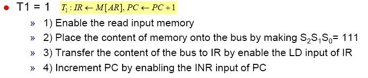
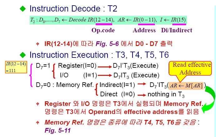
29 5.5 Instruction Cycle Fetch and Decode Fetch and Decode T0: AR PC (S 0 S 1 S 2 =010, T0=1) T1: IR M [AR], PC PC + 1 (S0S1S2=111, T1=1) T2: D0,..., D7 Decode IR(12-14), AR IR(0-11), I IR(15) T1 S 2 T0 S 1 Bus Memory unit Read Address S 0 7 AR 1 LD PC 2 INR IR 5 LD Common bus Clock
30 5.5 Instruction Cycle
31 5.5 Instruction Cycle
32 5.5 Instruction Cycle Register Reference Instruction Register Reference Instructions are identified when - D 7 = 1, I = 0 - Register Ref. Instr. is specified in B 0 ~ B 11 of IR - Execution starts with timing signal T 3 r = D 7 I T 3 => Register Reference Instruction B i = IR(i), i=0,1,2,...,11, the ith bit of IR. r: SC 0 CLA rb 11 : AC 0 CLE rb 10 : E 0 CMA rb 9 : AC AC CME rb 8 : E E CIR rb 7 : AC shr AC, AC(15) E, E AC(0) CIL rb 6 : AC shl AC, AC(0) E, E AC(15) INC rb 5 : AC AC + 1 SPA rb 4 : if (AC(15) = 0) then (PC PC+1) SNA rb 3 : if (AC(15) = 1) then (PC PC+1) SZA rb 2 : if (AC = 0) then (PC PC+1) SZE rb 1 : if (E = 0) then (PC PC+1) HLT rb 0 : S 0 (S is a start-stop flip-flop)
33 5.6 Memory Reference Instruction Opcode ( ) or the decoded output Di (i = 0,..., 6) are use d to select one memory-reference operation out of 7.
34 5.6 Memory Reference Instruction - The effective address of the instruction is in AR and was placed there during timing signal T 2 when I = 0, or during timing signal T3 when I = 1 Memory cycle is assumed to be short enough to be completed in a CPU cycle The execution of MR Instruction starts with T 4 AND to AC D 0 T 4 : DR M[AR] Read operand D 0 T 5 : AC AC DR, SC 0 AND with AC ADD to AC D 1 T 4 : DR M[AR] Read operand D 1 T 5 : AC AC + DR, E C out, SC 0 Add to AC and store carry in E
35 5.6 Memory Reference Instruction LDA: Load to AC D 2 T 4 : DR M[AR] D 2 T 5 : AC DR, SC 0 STA: Store AC D 3 T 4 : M[AR] AC, SC 0 BUN: Branch Unconditionally D 4 T 4 : PC AR, SC 0 BSA: Branch and Save Return Address M[AR] PC, PC AR + 1 Memory, PC, AR at time T BSA 135 Return address: PC = 21 Next instruction Memory, PC after execution 20 0 BSA Next instruction AR = Subroutine PC = 136 Subroutine 1 BUN BUN 135 Memory Memory
36 5.6 Memory Reference Instruction BSA: executed in a sequence of two micro-operations: D 5 T 4 : M[AR] PC, AR AR + 1 D 5 T 5 : PC AR, SC 0 ISZ: Increment and Skip-if-Zero D 6 T 4 : DR M[AR] D 6 T 5 : DR DR + 1 D 6 T6: M[AR] DR, if (DR = 0) then (PC PC + 1), SC 0
37 5.6 Memory Reference Instruction Memory-reference instruction AND ADD LDA STA D 0 T 4 D 1 T 4 D 2 T 4 D 3 T 4 DR M[AR] DR M[AR] DR M[AR] M[AR] AC SC 0 D 0 T 5 D 1 T 5 D 2 T 5 AC AC DR SC <- 0 AC AC + DR E Cout SC 0 AC DR SC 0 BUN BSA ISZ PC AR SC 0 D T 4 4 D T 5 4 D T 6 4 M[AR] PC AR AR + 1 PC AR SC 0 DR M[AR] D T 5 5 D T 6 5 DR DR + 1 D 6 T 6 M[AR] DR If (DR = 0) then (PC PC + 1) SC 0
38 5.7 Input-Output and Interrupt
39 5.7 Input-Output and Interrupt

40 5.7 Input-Output and Interrupt
41 5.7 Input-Output and Interrupt Interrupt

42 5.7 Input-Output and Interrupt

43 5.8 Complete Computer Description
44 5.8 Complete Computer Description
45 5.8 Complete Computer Description
UNIT:2 BASIC COMPUTER ORGANIZATION AND DESIGN
 1 UNIT:2 BASIC COMPUTER ORGANIZATION AND DESIGN BASIC COMPUTER ORGANIZATION AND DESIGN 2.1 Instruction Codes 2.2 Computer Registers AC or Accumulator, Data Register or DR, the AR or Address Register, program
Basic Computer Organization and Design Part 2/3
 Basic Computer Organization and Design Part 2/3 Adapted by Dr. Adel Ammar Computer Organization Basic Computer Instructions Basic Computer Instruction Format Memory-Reference Instructions (OP-code = 000
Computer Organization (Autonomous)
") Computer Organization (Autonomous) UNIT II Sections - A & D Prepared by Anil Kumar Prathipati, Asst. Prof., Dept. of CSE. SYLLABUS Basic Computer Organization and Design: Instruction codes Stored Program
Computer Organization (Autonomous) UNIT II Sections - A & D Prepared by Anil Kumar Prathipati, Asst. Prof., Dept. of CSE. SYLLABUS Basic Computer Organization and Design: Instruction codes Stored Program
BASIC COMPUTER ORGANIZATION AND DESIGN
 1 BASIC COMPUTER ORGANIZATION AND DESIGN Instruction Codes Computer Registers Computer Instructions Timing and Control Instruction Cycle Memory Reference Instructions Input-Output and Interrupt Complete
5-1 Instruction Codes
 Chapter 5: Lo ai Tawalbeh Basic Computer Organization and Design 5-1 Instruction Codes The Internal organization of a digital system is defined by the sequence of microoperations it performs on data stored
CHAPTER 5 Basic Organization and Design Outline Instruction Codes Computer Registers Computer Instructions Timing and Control Instruction Cycle
 CS 224: Computer Organization S.KHABET CHAPTER 5 Basic Organization and Design Outline Instruction Codes Computer Registers Computer Instructions Timing and Control Instruction Cycle Memory Reference Instructions
Basic Computer Organization - Designing your first computer. Acknowledgment: Most of the slides are adapted from Prof. Hyunsoo Yoon s slides.
 Basic Computer Organization - Designing your first computer Acknowledgment: Most of the slides are adapted from Prof. Hyunsoo Yoon s slides. 1 This week- BASIC COMPUTER ORGANIZATION AND DESIGN Instruction
BASIC COMPUTER ORGANIZATION AND DESIGN
 BASIC COMPUTER ORGANIZATION AND DESIGN Instruction Codes Computer Registers Computer Instructions Timing and Control Instruction Cycle Memory Reference Instructions Input-Output and Interrupt Complete
BASIC COMPUTER ORGANIZATION AND DESIGN
 1 BASIC COMPUTER ORGANIZATION AND DESIGN Instruction Codes Computer Registers Computer Instructions Timing and Control Instruction Cycle Memory Reference Instructions Input-Output and Interrupt Complete
csitnepal Unit 3 Basic Computer Organization and Design
 Unit 3 Basic Computer Organization and Design Introduction We introduce here a basic computer whose operation can be specified by the resister transfer statements. Internal organization of the computer
CHAPTER SIX BASIC COMPUTER ORGANIZATION AND DESIGN
 CHAPTER SIX BASIC COMPUTER ORGANIZATION AND DESIGN 6.1. Instruction Codes The organization of a digital computer defined by: 1. The set of registers it contains and their function. 2. The set of instructions
COMPUTER ORGANIZATION
 COMPUTER ORGANIZATION INDEX UNIT-II PPT SLIDES Srl. No. Module as per Session planner Lecture No. PPT Slide No. 1. Register Transfer language 2. Register Transfer Bus and memory transfers 3. Arithmetic
Computer Architecture and Organization: L06: Instruction Cycle
 Computer Architecture and Organization: L06: Instruction Cycle By: A. H. Abdul Hafez Abdul.hafez@hku.edu.tr, ah.abdulhafez@gmail.com 1 Outlines 1. Fetch and decode 2. Determine the Type of Instruction
Computer Organization and Design
 CSE211 Computer Organization and Design Lecture : 3 Tutorial: 1 Practical: 0 Credit: 4 KIDS Labs 1 Unit 1 : Basics of Digital Electronics Introduction Logic Gates Flip Flops Decoder Encoder Multiplexers
Unit II Basic Computer Organization
 1. Define the term. Internal Organization-The internal organization of a digital system is defined by the sequence of microoperations it performs on data stored in its registers. Program- A program is
Programming Level A.R. Hurson Department of Computer Science Missouri University of Science & Technology Rolla, Missouri
 Programming Level A.R. Hurson Department of Computer Science Missouri University of Science & Technology Rolla, Missouri 65409 hurson@mst.edu A.R. Hurson 1 Programming Level Computer: A computer with a
Computer Architecture
 http://www.bsccsit.com/ Computer Architecture CSC. 201 Third Semester Prepared By: Arjun Singh Saud Special thanks to Mr. Arjun Singh Saud for providing this valuable note! Chapter 1 Data representation
C.P.U Organization. Memory Unit. Central Processing Unit (C.P.U) Input-Output Processor (IOP) Figure (1) Digital Computer Block Diagram
 Input-Output Processor (IOP) Figure (1) Digital Computer Block Diagram") C.P.U Organization 1.1 Introduction A computer system is sometimes subdivided into two functional entities "Hardware" and "Software". The H/W of the computer consists of all the electronic components and
C.P.U Organization 1.1 Introduction A computer system is sometimes subdivided into two functional entities "Hardware" and "Software". The H/W of the computer consists of all the electronic components and
Blog -
 . Instruction Codes Every different processor type has its own design (different registers, buses, microoperations, machine instructions, etc) Modern processor is a very complex device It contains Many
Midterm Examination # 2 Wednesday, March 18, Duration of examination: 75 minutes
 Page 1 of 8 School of Computer Science 60-265-01 Computer Architecture and Digital Design Winter 2009 Midterm Examination # 2 Wednesday, March 18, 2009 Student Name: First Name Family Name Student ID Number:
Faculty of Engineering Systems & Biomedical Dept. First Year Cairo University Sheet 6 Computer I
 aculty of Engineering Systems & Biomedical Dept. irst Year Cairo University Sheet 6 Computer I 1. Choose rue or alse for each of the following statements a) In a direct addressing mode instruction, the
Computer architecture Assignment 3
 Computer architecture Assignment 3 1- An instruction at address 14E in the basic computer has I=0, an operation code of the AND instruction, and an address part equal to 109(all numbers are in hexadecimal).
Computer Organization and Architecture
 Computer Organization and Architecture Dr Binu P Chacko Associate Professor Department of Computer Science Prajyoti Niketan College, Pudukad, THRISSUR Instruction Codes Computer organization is defined
Computer Architecture
 Computer Architecture Lecture 1: Digital logic circuits The digital computer is a digital system that performs various computational tasks. Digital computers use the binary number system, which has two
Chapter 16. Control Unit Operation. Yonsei University
 Chapter 16 Control Unit Operation Contents Micro-Operation Control of the Processor Hardwired Implementation 16-2 Micro-Operations Micro-Operations Micro refers to the fact that each step is very simple
Darshan Institute of Engineering & Technology for Diploma Studies Unit - 1
 Darshan Institute of Engineering & Technology for Diploma Studies Unit - 1 1. Draw and explain 4 bit binary arithmetic or adder circuit diagram. A binary parallel adder is digital function that produces
COMPUTER ARCHITECTURE AND ORGANIZATION Register Transfer and Micro-operations 1. Introduction A digital system is an interconnection of digital
 Register Transfer and Micro-operations 1. Introduction A digital system is an interconnection of digital hardware modules that accomplish a specific information-processing task. Digital systems vary in
جامعة بنها - كمية العموم قسم الرياضيات المستوي الرابع )علوم حاسب( يوم االمتحان: االحد تاريخ االمتحان: 1024 / 21 / 12 المادة :
علوم حاسب( يوم االمتحان: االحد تاريخ االمتحان: 1024 / 21 / 12 المادة :") جامعة بنها - كمية العموم قسم الرياضيات المستوي الرابع )علوم حاسب( يوم االمتحان: االحد تاريخ االمتحان: 1024 / 21 / 12 م المادة : بنية الحاسب )124 رس( الممتحن: د/ مصعب عبد الحميد محمد حسان مدرس بقسم الرياضيات
جامعة بنها - كمية العموم قسم الرياضيات المستوي الرابع )علوم حاسب( يوم االمتحان: االحد تاريخ االمتحان: 1024 / 21 / 12 م المادة : بنية الحاسب )124 رس( الممتحن: د/ مصعب عبد الحميد محمد حسان مدرس بقسم الرياضيات
COMPUTER ARCHITECTURE AND DIGITAL DESIGN
 SPECIAL MAKEUP - FINAL EXAMINATION COMPUTER ARCHITECTURE AND DIGITAL DESIGN 03-60-265-01 S C H O O L O F C O M P U T E R S C I E N C E - U N I V E R S I T Y O F W I N D S O R Fall 2008 Last Name: First
Class Notes. Dr.C.N.Zhang. Department of Computer Science. University of Regina. Regina, SK, Canada, S4S 0A2
 Class Notes CS400 Part VI Dr.C.N.Zhang Department of Computer Science University of Regina Regina, SK, Canada, S4S 0A2 C. N. Zhang, CS400 83 VI. CENTRAL PROCESSING UNIT 1 Set 1.1 Addressing Modes and Formats
Introduction. Machine Language. Assembly Language. Assembler. Program Loops. Programming Arithmetic and Logic Operations.
 Computer System AA rc hh ii tec ture( 66 )) PROGRAMMING THE BASIC COMPUTER Introduction Machine Language Assembly Language Assembler Program Loops Programming Arithmetic and Logic Operations Subroutines
Register Transfer and Micro-operations
 Register Transfer Language Register Transfer Bus Memory Transfer Micro-operations Some Application of Logic Micro Operations Register Transfer and Micro-operations Learning Objectives After reading this
There are four registers involved in the fetch cycle: MAR, MBR, PC, and IR.
 CS 320 Ch. 20 The Control Unit Instructions are broken down into fetch, indirect, execute, and interrupt cycles. Each of these cycles, in turn, can be broken down into microoperations where a microoperation
REGISTER TRANSFER LANGUAGE
 REGISTER TRANSFER LANGUAGE The operations executed on the data stored in the registers are called micro operations. Classifications of micro operations Register transfer micro operations Arithmetic micro
THE MICROPROCESSOR Von Neumann s Architecture Model
 THE ICROPROCESSOR Von Neumann s Architecture odel Input/Output unit Provides instructions and data emory unit Stores both instructions and data Arithmetic and logic unit Processes everything Control unit
SCRAM Introduction. Philipp Koehn. 19 February 2018
 SCRAM Introduction Philipp Koehn 19 February 2018 This eek 1 Fully work through a computer circuit assembly code Simple but Complete Random Access Machine (SCRAM) every instruction is 8 bit 4 bit for op-code:
CHAPTER SEVEN PROGRAMMING THE BASIC COMPUTER
 CHAPTER SEVEN 71 Introduction PROGRAMMING THE BASIC COMPUTER A computer system as it was mentioned before in chapter 1, it is subdivided into two functional parts: 1 Hardware, which consists of all physical
REGISTER TRANSFER AND MICROOPERATIONS
 1 REGISTER TRANSFER AND MICROOPERATIONS Register Transfer Language Register Transfer Bus and Memory Transfers Arithmetic Microoperations Logic Microoperations Shift Microoperations Arithmetic Logic Shift
William Stallings Computer Organization and Architecture
 William Stallings Computer Organization and Architecture Chapter 16 Control Unit Operations Rev. 3.2 (2009-10) by Enrico Nardelli 16-1 Execution of the Instruction Cycle It has many elementary phases,
MICROPROGRAMMED CONTROL
 MICROPROGRAMMED CONTROL Hardwired Control Unit: When the control signals are generated by hardware using conventional logic design techniques, the control unit is said to be hardwired. Micro programmed
Computer Architecture Programming the Basic Computer
 4. The Execution of the EXCHANGE Instruction The EXCHANGE routine reads the operand from the effective address and places it in DR. The contents of DR and AC are interchanged in the third microinstruction.
UNIT - V MEMORY P.VIDYA SAGAR ( ASSOCIATE PROFESSOR) Department of Electronics and Communication Engineering, VBIT
 Department of Electronics and Communication Engineering, VBIT") UNIT - V MEMORY P.VIDYA SAGAR ( ASSOCIATE PROFESSOR) contents Memory: Introduction, Random-Access memory, Memory decoding, ROM, Programmable Logic Array, Programmable Array Logic, Sequential programmable
UNIT - V MEMORY P.VIDYA SAGAR ( ASSOCIATE PROFESSOR) contents Memory: Introduction, Random-Access memory, Memory decoding, ROM, Programmable Logic Array, Programmable Array Logic, Sequential programmable
Digital System Design Using Verilog. - Processing Unit Design
 Digital System Design Using Verilog - Processing Unit Design 1.1 CPU BASICS A typical CPU has three major components: (1) Register set, (2) Arithmetic logic unit (ALU), and (3) Control unit (CU) The register
Lecture1: introduction. Outline: History overview Central processing unite Register set Special purpose address registers Datapath Control unit
 Lecture1: introduction Outline: History overview Central processing unite Register set Special purpose address registers Datapath Control unit 1 1. History overview Computer systems have conventionally
REGISTER TRANSFER AND MICROOPERATIONS
 REGISTER TRANSFER AND MICROOPERATIONS Register Transfer Language Register Transfer Bus and Memory Transfers Arithmetic Microoperations Logic Microoperations Shift Microoperations Arithmetic Logic Shift
Combinational and sequential circuits (learned in Chapters 1 and 2) can be used to create simple digital systems.
 can be used to create simple digital systems.") REGISTER TRANSFER AND MICROOPERATIONS Register Transfer Language Register Transfer Bus and Memory Transfers Arithmetic Microoperations Logic Microoperations Shift Microoperations Arithmetic Logic Shift
REGISTER TRANSFER AND MICROOPERATIONS Register Transfer Language Register Transfer Bus and Memory Transfers Arithmetic Microoperations Logic Microoperations Shift Microoperations Arithmetic Logic Shift
Chapter 3 : Control Unit
 3.1 Control Memory Chapter 3 Control Unit The function of the control unit in a digital computer is to initiate sequences of microoperations. When the control signals are generated by hardware using conventional
CPU Design John D. Carpinelli, All Rights Reserved 1
 CPU Design 1997 John D. Carpinelli, All Rights Reserved 1 Outline Register organization ALU design Stacks Instruction formats and types Addressing modes 1997 John D. Carpinelli, All Rights Reserved 2 We
Blog - https://anilkumarprathipati.wordpress.com/
 Control Memory 1. Introduction The function of the control unit in a digital computer is to initiate sequences of microoperations. When the control signals are generated by hardware using conventional
COMPUTER ORGANIZATION AND ARCHITECTURE
 Page 1 1. Which register store the address of next instruction to be executed? A) PC B) AC C) SP D) NONE 2. How many bits are required to address the 128 words of memory? A) 7 B) 8 C) 9 D) NONE 3. is the
CHAPTER 8: Central Processing Unit (CPU)
") CS 224: Computer Organization S.KHABET CHAPTER 8: Central Processing Unit (CPU) Outline Introduction General Register Organization Stack Organization Instruction Formats Addressing Modes 1 Major Components
CS 224: Computer Organization S.KHABET CHAPTER 8: Central Processing Unit (CPU) Outline Introduction General Register Organization Stack Organization Instruction Formats Addressing Modes 1 Major Components
Micro-Operations. execution of a sequence of steps, i.e., cycles
 Micro-Operations Instruction execution execution of a sequence of steps, i.e., cycles Fetch, Indirect, Execute & Interrupt cycles Cycle - a sequence of micro-operations Micro-operations data transfer between
STRUCTURE OF DESKTOP COMPUTERS
 Page no: 1 UNIT 1 STRUCTURE OF DESKTOP COMPUTERS The desktop computers are the computers which are usually found on a home or office desk. They consist of processing unit, storage unit, visual display
CHAPTER 4: Register Transfer Language and Microoperations
 CS 224: Computer Organization S.KHABET CHAPTER 4: Register Transfer Language and Microoperations Outline Register Transfer Language Register Transfer Bus and Memory Transfers Arithmetic Microoperations
Effective Approach for Teaching Computer System Architecture
 Effective Approach for Teaching Computer System Architecture K. M. Hasam 1, Akhlaq A Khan 2, M. Saleem 3, M Riaz Moghal 3, asir Mahmood 4, M. Adnan 5, Tanveer Akhtar 6 1,3 Department of Electrical Engineering,
Advanced Parallel Architecture Lesson 3. Annalisa Massini /2015
 Advanced Parallel Architecture Lesson 3 Annalisa Massini - 2014/2015 Von Neumann Architecture 2 Summary of the traditional computer architecture: Von Neumann architecture http://williamstallings.com/coa/coa7e.html
UNIT-III REGISTER TRANSFER LANGUAGE AND DESIGN OF CONTROL UNIT
 UNIT-III 1 KNREDDY UNIT-III REGISTER TRANSFER LANGUAGE AND DESIGN OF CONTROL UNIT Register Transfer: Register Transfer Language Register Transfer Bus and Memory Transfers Arithmetic Micro operations Logic
Computer Organization (Autonomous)
") Computer Organization (Autonomous) UNIT I Sections - A & D Prepared by Anil Kumar Prathipati, Asst. Prof., Dept. of CSE. SYLLABUS Introduction: Types of Computers, Functional units of Basic Computer (Block
Computer Organization (Autonomous) UNIT I Sections - A & D Prepared by Anil Kumar Prathipati, Asst. Prof., Dept. of CSE. SYLLABUS Introduction: Types of Computers, Functional units of Basic Computer (Block
M. Sc (CS) (II Semester) Examination, Subject: Computer System Architecture Paper Code: M.Sc-CS-203. Time: Three Hours] [Maximum Marks: 60
![M. Sc (CS) (II Semester) Examination, Subject: Computer System Architecture Paper Code: M.Sc-CS-203. Time: Three Hours] [Maximum Marks: 60](/thumbs/87/96339673.jpg "M. Sc (CS) (II Semester) Examination, Subject: Computer System Architecture Paper Code: M.Sc-CS-203. Time: Three Hours] [Maximum Marks: 60") M. Sc (CS) (II Semester) Examination, 2012-13 Subject: Computer System Architecture Paper Code: M.Sc-CS-203 Time: Three Hours] [Maximum Marks: 60 Note: Question Number 1 is compulsory. Answer any four
M. Sc (CS) (II Semester) Examination, 2012-13 Subject: Computer System Architecture Paper Code: M.Sc-CS-203 Time: Three Hours] [Maximum Marks: 60 Note: Question Number 1 is compulsory. Answer any four
For Example: P: LOAD 5 R0. The command given here is used to load a data 5 to the register R0.
 Register Transfer Language Computers are the electronic devices which have several sets of digital hardware which are inter connected to exchange data. Digital hardware comprises of VLSI Chips which are
Assembly Language Programming of 8085
 Assembly Language Programming of 8085 Topics 1. Introduction 2. Programming model of 8085 3. Instruction set of 8085 4. Example Programs 5. Addressing modes of 8085 6. Instruction & Data Formats of 8085
UNIT-II. Part-2: CENTRAL PROCESSING UNIT
 Page1 UNIT-II Part-2: CENTRAL PROCESSING UNIT Stack Organization Instruction Formats Addressing Modes Data Transfer And Manipulation Program Control Reduced Instruction Set Computer (RISC) Introduction:
Basic Processing Unit: Some Fundamental Concepts, Execution of a. Complete Instruction, Multiple Bus Organization, Hard-wired Control,
 UNIT - 7 Basic Processing Unit: Some Fundamental Concepts, Execution of a Complete Instruction, Multiple Bus Organization, Hard-wired Control, Microprogrammed Control Page 178 UNIT - 7 BASIC PROCESSING
Module 5 - CPU Design
 Module 5 - CPU Design Lecture 1 - Introduction to CPU The operation or task that must perform by CPU is: Fetch Instruction: The CPU reads an instruction from memory. Interpret Instruction: The instruction
COA. Prepared By: Dhaval R. Patel Page 1. Q.1 Define MBR.
 Q.1 Define MBR. MBR( Memory buffer register) A Memory Buffer Register (MBR) is the register in a computers processor that stores the data being transferred to and from the devices It allowing the processor
Outcomes. Lecture 13 - Introduction to the Central Processing Unit (CPU) Central Processing UNIT (CPU) or Processor
 Central Processing UNIT (CPU) or Processor") Lecture 13 - Introduction to the Central Processing Unit (CPU) Outcomes What is a CPU? How are instructions prepared by the CPU before execution? What registers and operations are involved in this preparation
Lecture 13 - Introduction to the Central Processing Unit (CPU) Outcomes What is a CPU? How are instructions prepared by the CPU before execution? What registers and operations are involved in this preparation
Fig: Computer memory with Program, data, and Stack. Blog - NEC (Autonomous) 1
 1") Central Processing Unit 1. Stack Organization A useful feature that is included in the CPU of most computers is a stack or last in, first out (LIFO) list. A stack is a storage device that stores information
Central Processing Unit 1. Stack Organization A useful feature that is included in the CPU of most computers is a stack or last in, first out (LIFO) list. A stack is a storage device that stores information
PSIM: Processor SIMulator (version 4.2)
") PSIM: Processor SIMulator (version 4.2) by Charles E. Stroud, Professor Dept. of Electrical & Computer Engineering Auburn University July 23, 2003 ABSTRACT A simulator for a basic stored program computer
PSIM: Processor SIMulator (version 4.2) by Charles E. Stroud, Professor Dept. of Electrical & Computer Engineering Auburn University July 23, 2003 ABSTRACT A simulator for a basic stored program computer
session 7. Datapath Design
 General Objective: Determine the hardware requirement of a digital computer based on its instruction set. Specific Objectives: Describe the general concepts in designing the data path of a digital computer
Chapter 20 - Microprogrammed Control (9 th edition)
") Chapter 20 - Microprogrammed Control (9 th edition) Luis Tarrataca luis.tarrataca@gmail.com CEFET-RJ L. Tarrataca Chapter 20 - Microprogrammed Control 1 / 47 Table of Contents I 1 Motivation 2 Basic Concepts
Chapter 20 - Microprogrammed Control (9 th edition) Luis Tarrataca luis.tarrataca@gmail.com CEFET-RJ L. Tarrataca Chapter 20 - Microprogrammed Control 1 / 47 Table of Contents I 1 Motivation 2 Basic Concepts
EE 3170 Microcontroller Applications
 EE 3170 Microcontroller Applications Lecture 4 : Processors, Computers, and Controllers - 1.2 (reading assignment), 1.3-1.5 Based on slides for ECE3170 by Profs. Kieckhafer, Davis, Tan, and Cischke Outline
DC57 COMPUTER ORGANIZATION JUNE 2013
 Q2 (a) How do various factors like Hardware design, Instruction set, Compiler related to the performance of a computer? The most important measure of a computer is how quickly it can execute programs.
Processing Unit CS206T
 Processing Unit CS206T Microprocessors The density of elements on processor chips continued to rise More and more elements were placed on each chip so that fewer and fewer chips were needed to construct
INSTRUCTION SET OF 8085
 INSTRUCTION SET OF 8085 Instruction Set of 8085 An instruction is a binary pattern designed inside a microprocessor to perform a specific function. The entire group of instructions that a microprocessor
TYPES OF INTERRUPTS: -
 There are 3 types of interrupts. TYPES OF INTERRUPTS: - External Interrupts. Internal Interrupts. Software interrupts. Hardware Interrupts (1) External interrupts come from I/O devices, from a timing device
Computer Organization II CMSC 3833 Lecture 33
 Term MARIE Definition Machine Architecture that is Really Intuitive and Easy 4.8.1 The Architecture Figure s Architecture Characteristics: Binary, two s complement Stored program, fixed word length Word
IAS Computer. Instructions
 IAS Computer Instructions The IAS computer was designed in the 1940's and built in the early 1950's by John von Neumann at the Princeton Institute for Advanced Studies. It can arguably be called the father
CPU Structure and Function
 CPU Structure and Function Chapter 12 Lesson 17 Slide 1/36 Processor Organization CPU must: Fetch instructions Interpret instructions Fetch data Process data Write data Lesson 17 Slide 2/36 CPU With Systems
Microcomputer Architecture and Programming
 IUST-EE (Chapter 1) Microcomputer Architecture and Programming 1 Outline Basic Blocks of Microcomputer Typical Microcomputer Architecture The Single-Chip Microprocessor Microprocessor vs. Microcontroller
Computer Architecture and Organization: L09: CPU Organization
 Computer Architecture and Organization: L09: CPU Organization By: A. H. Abdul Hafez Abdul.hafez@hku.edu.tr, ah.abdulhafez@gmail.com, hafez@research.iiit.ac.in 1 CAO, by Dr. A.H. Abdul Hafez, CE Dept. HKU
Control Unit Implementation Hardwired Memory
 Chapter 7: Microprogrammed nit mplementation Hardwired nstruction code Sequence Counter Combinational Logic Circuits signals Microprogrammed nstruction code CAR: Register CDR: Data Register Next Generator
2 MARKS Q&A 1 KNREDDY UNIT-I
 2 MARKS Q&A 1 KNREDDY UNIT-I 1. What is bus; list the different types of buses with its function. A group of lines that serves as a connecting path for several devices is called a bus; TYPES: ADDRESS BUS,
Final Exam Review. b) Using only algebra, prove or disprove the following:
 Using only algebra, prove or disprove the following:") EE 254 Final Exam Review 1. The final exam is open book and open notes. It will be made up of problems similar to those on the previous 3 hour exams. For review, be sure that you can work all of the problems
EE 254 Final Exam Review 1. The final exam is open book and open notes. It will be made up of problems similar to those on the previous 3 hour exams. For review, be sure that you can work all of the problems
Architecture & Instruction set of 8085 Microprocessor and 8051 Micro Controller
 of 8085 microprocessor 8085 is pronounced as "eighty-eighty-five" microprocessor. It is an 8-bit microprocessor designed by Intel in 1977 using NMOS technology. It has the following configuration 8-bit
Note that none of the above MAY be a VALID ANSWER.
 ECE 270 Learning Outcome 4-1 - Practice Exam / Solution OUTCOME #4: An ability to design and implement computer logic circuits. Multiple Choice select the single most appropriate response for each question.
Register Transfer Language and Microoperations (Part 2)
") Register Transfer Language and Microoperations (Part 2) Adapted by Dr. Adel Ammar Computer Organization 1 MICROOPERATIONS Computer system microoperations are of four types: Register transfer microoperations
Register Transfer Language and Microoperations (Part 2) Adapted by Dr. Adel Ammar Computer Organization 1 MICROOPERATIONS Computer system microoperations are of four types: Register transfer microoperations
EXPERIMENT NO. 1 THE MKT 8085 MICROPROCESSOR TRAINER
 OBJECT: EXPERIMENT NO. 1 THE MKT 8085 MICROPROCESSOR TRAINER To understand the structure and operating instruction of the microprocessor trainer. INTRODUCTION: The MKT 8085 is a single-board microcomputer,
Computer Architecture and Organization: L04: Micro-operations
 Computer Architecture and Organization: L4: Micro-operations By: A. H. Abdul Hafez Abdul.hafez@hku.edu.tr, ah.abdulhafez@gmail.com, hafez@research.iiit.ac.in 1 Outlines 1. Arithmetic microoperation 2.
Roll No TCS 402/TIT 402
 Roll No TCS 402/TIT 402 Mid Term Examination March 2016 B.Tech (IV Semester) Computer Organization Time: Two (2) Hrs. Maximum Marks: 60 NOTE: (i) (ii) (iii) (iv) This question paper contains three questions
Chapter 4. MARIE: An Introduction to a Simple Computer. Chapter 4 Objectives. 4.1 Introduction. 4.2 CPU Basics
 Chapter 4 Objectives Learn the components common to every modern computer system. Chapter 4 MARIE: An Introduction to a Simple Computer Be able to explain how each component contributes to program execution.
 Part A Questions 1. What is an ISP? ISP stands for Instruction Set Processor. This unit is simply called as processor which executes machine instruction and coordinates the activities of other units..
Computer Logic II CCE 2010
 Computer Logic II CCE 2010 Dr. Owen Casha Computer Logic II 1 The Processing Unit Computer Logic II 2 The Processing Unit In its simplest form, a computer has one unit that executes program instructions.
Basics of Microprocessor
 Unit 1 Basics of Microprocessor 1. Microprocessor Microprocessor is a multipurpose programmable integrated device that has computing and decision making capability. This semiconductor IC is manufactured
Chapter 10 Computer Design Basics
 Logic and Computer Design Fundamentals Chapter 10 Computer Design Basics Part 2 A Simple Computer Charles Kime & Thomas Kaminski 2004 Pearson Education, Inc. Terms of Use (Hyperlinks are active in View
SISTEMI EMBEDDED. Computer Organization Central Processing Unit (CPU) Federico Baronti Last version:
 Federico Baronti Last version:") SISTEMI EMBEDDED Computer Organization Central Processing Unit (CPU) Federico Baronti Last version: 20170516 Processing Unit A processor reads program instructions from the computer s memory and executes
SISTEMI EMBEDDED Computer Organization Central Processing Unit (CPU) Federico Baronti Last version: 20170516 Processing Unit A processor reads program instructions from the computer s memory and executes
MAHALAKSHMI ENGINEERING COLLEGE TIRUCHIRAPALLI UNIT I THE 8085 & 8086 MICROPROCESSORS. PART A (2 Marks)
") MAHALAKSHMI ENGINEERING COLLEGE TIRUCHIRAPALLI-621213. UNIT I THE 8085 & 8086 MICROPROCESSORS PART A (2 Marks) 1. Give the significance of SIM and RIM instruction available in 8085. [NOV/DEC 2006] Instruction
MAHALAKSHMI ENGINEERING COLLEGE TIRUCHIRAPALLI-621213. UNIT I THE 8085 & 8086 MICROPROCESSORS PART A (2 Marks) 1. Give the significance of SIM and RIM instruction available in 8085. [NOV/DEC 2006] Instruction
The CPU and Memory. How does a computer work? How does a computer interact with data? How are instructions performed? Recall schematic diagram:
 The CPU and Memory How does a computer work? How does a computer interact with data? How are instructions performed? Recall schematic diagram: 1 Registers A register is a permanent storage location within
Chapter 4. MARIE: An Introduction to a Simple Computer
 Chapter 4 MARIE: An Introduction to a Simple Computer Chapter 4 Objectives Learn the components common to every modern computer system. Be able to explain how each component contributes to program execution.
The register set differs from one computer architecture to another. It is usually a combination of general-purpose and special purpose registers
 Part (6) CPU BASICS A typical CPU has three major components: 1- register set, 2- arithmetic logic unit (ALU), 3- control unit (CU). The figure below shows the internal structure of the CPU. The CPU fetches
Control unit. Input/output devices provide a means for us to make use of a computer system. Computer System. Computer.
 Lecture 6: I/O and Control I/O operations Control unit Microprogramming Zebo Peng, IDA, LiTH 1 Input/Output Devices Input/output devices provide a means for us to make use of a computer system. Computer