Example Plate with a hole
|
|
|
- Chester Briggs
- 6 years ago
- Views:
Transcription
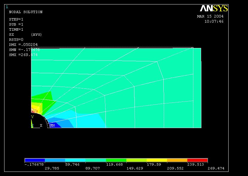
1 Course in ANSYS Example Plate with a hole A Objective: Determine the maximum stress in the x-direction for point A and display the deformation figure Tasks: Create a submodel to increase the accuracy of the FEA without increasing the computational effort significantly? Topics: Element type, Real constants, modeling, mapped mesh, plot results, output graphics, path operations, submodeling E = N/mm2 n = 0.3 a = 200mm b = 100mm t = 10mm r = 10mm 2 s = 100N/mm 2 1
. Analyze the submodel.")

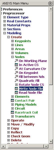
2 Steps in Submodeling The process for using submodeling is as follows: Create and analyze the coarse model. Create the submodel. Perform cut boundary interpolation (CBI). Analyze the submodel. Verify that the distance between the cut boundaries and the stress concentration is adequate. 3 Example - title Utility Menu > File > Change Jobname /jobname, _coarse GUI Command line entry Enter: _coarse Utility Menu > File > Change Title /title, Plate with a hole Enter: Plate with a hole 4 2
 and Y=(0,50) Enter 0 or leave empty Enter")
 are automatically generated (also numbered automatically) 5 Example Areas")
3 Example Areas Rectangle Preprocessor > Modeling > Create > Areas > Rectangle > By Dimensions Create an area given by X=(0,100) and Y=(0,50) Enter 0 or leave empty Enter 100 Press OK Enter 0 or leave empty Enter 50 Note: Keypoints (4 kp s) and lines (4 lines) are automatically generated (also numbered automatically) 5 Example Areas Rectangle 6 3
4 Example Areas Circle Preprocessor > Modeling > Create > Areas > Circle > Solid Circle Create an area given by (X,Y)=(0, 0) and Radius=10 Enter 10 Press OK Note: Keypoints (4 kp s) and lines (4 lines) are automatically generated (also numbered automatically) 7 Example - Area 8 4
5 Example - Operate Preprocessor > Modeling > Operate > Booleans > Subtract > Areas Create the final area by subtracting the circular area from the rectangular area Note: Bottom left corner of ANSYS GUI Select the rectangular area and press OK Note: Bottom left corner of ANSYS GUI Select the circular area Press OK 9 Example Areas 10 5
6

7 Example - Plot Menu Plot Keypoint, Lines, and Areas 13 Example Element Type Preprocessor > Element Type > Add/Edit/Delete Press Add 14 7
8 Example - Element Type Preprocessor > Element Type > Add/Edit/Delete Select Plane strs w/thk Press Options Press Help to learn more about the element. 15 Example Real Constants Preprocessor > Real Constants > Add Place the cursor on the relevant element and press OK 16 8
9 Example - Real Constants Preprocessor > Real Constants > Add Enter 10 Press Close to finish Press OK 17 Example - Material Properties Preprocessor > Material Props > Material Models Double Click to step in the material tree 18 9
10 Example - Material Properties Preprocessor > Material Props > Material Models Enter Modulus of elasticity Click here to Close Enter 0.3 Poisson s ratio Press OK 19 Example - Meshing Preprocessor > Meshing > Size Cntrls > ManualSize > Lines > Picked Lines Select/Pick Lines to specify mesh size for See next page Pick the two longest lines Press OK when finish with selection 20 10
11

12 Example - Meshing Preprocessor > Meshing > Mesh > Areas > Mapped > 3 or 4 sided Select individual areas to be meshed NB: It is often necessary to Clear the model for example if Element Type or model geometry is to be changed Select all areas defined to be meshed 23 Example Mapped Mesh 24 12


13 Example Analysis Type File > Write DB log file Enter example0702_coarse.lgw Solution > Analysis Type > New Analysis 25 Example Define Loads Solution > Define Loads > Apply > Structural > Displacement > On Lines Select UY to fix the plate in the y-direction Select the bottom straight line Press OK 26 13


14 Example Define Loads Solution > Define Loads > Apply > Structural > Displacement > On Lines Select UX to fix the plate in the x-direction Select the left straight line Press OK 27 Example Define Loads Solution > Define Loads > Apply > Structural > Pressure > On lines Select the right straight line Enter -100 Press OK to finish Note: Pressure acts normal and inward to a surface 28 14


15 Example - Save Display of Analysis model Save the model 29 Example - Solve Solution > Solve > Current LS Press OK 30 15
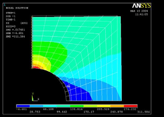
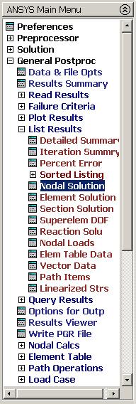
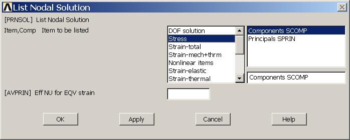
16 Example - Solve Press Close Press here to Close 31 Example Contour Plot General Postproc > Plot Results > Contour Plot > Nodal Sol Select Stress Select SX for stresses in x-direction 32 16
17
18
19
20
21

22
23
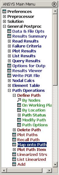
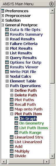
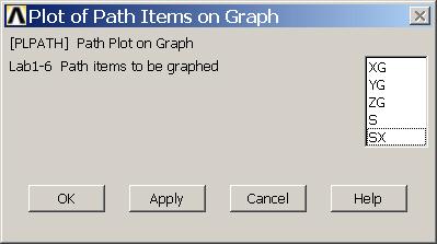
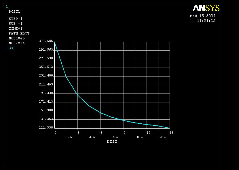
24 Example Plot Path on Graph 47 Steps in Submodeling The process for using submodeling is as follows: Create and analyze the coarse model. Create the submodel. Perform cut boundary interpolation (CBI). Analyze the submodel. Verify that the distance between the cut boundaries and the stress concentration is adequate
25 Example - title Utility Menu > File > Change Jobname /jobname, _fine GUI Command line entry Enter: _fine Utility Menu > File > Change Title /title, Plate with a hole Enter: Plate with a hole 49 Example Areas Rectangle Preprocessor > Modeling > Create > Areas > Rectangle > By Dimensions Create an area given by X=(0,25) and Y=(0,25) Enter 0 or leave empty Enter 25 Press OK Enter 0 or leave empty Enter 25 Note: Keypoints (4 kp s) and lines (4 lines) are automatically generated (also numbered automatically) 50 25
26 Example Areas Rectangle 51 Example Areas Circle Preprocessor > Modeling > Create > Areas > Circle > Solid Circle Create an area given by (X,Y)=(0, 0) and Radius=10 Enter 10 Press OK Note: Keypoints (4 kp s) and lines (4 lines) are automatically generated (also numbered automatically) 52 26

27 Example - Area 53 Example - Operate Preprocessor > Modeling > Operate > Booleans > Subtract > Areas Create the final area by subtracting the circular area from the rectangular area Note: Bottom left corner of ANSYS GUI Select the rectangular area and press OK Note: Bottom left corner of ANSYS GUI Select the circular area Press OK 54 27
28
29

30 Example Element Type Preprocessor > Element Type > Add/Edit/Delete Press Add 59 Example - Element Type Preprocessor > Element Type > Add/Edit/Delete Select Plane strs w/thk Press Options Press Help to learn more about the element


31 Example Real Constants Preprocessor > Real Constants > Add Place the cursor on the relevant element and press OK 61 Example - Real Constants Preprocessor > Real Constants > Add Enter 10 Press Close to finish Press OK 62 31


32 Example - Material Properties Preprocessor > Material Props > Material Models Double Click to step in the material tree 63 Example - Material Properties Preprocessor > Material Props > Material Models Enter: Modulus of elasticity Click here to Close Enter: Poisson s ratio Press OK 64 32

33 Example - Meshing Preprocessor > Meshing > Size Cntrls > ManualSize > Lines > Picked Lines Select/Pick Lines to specify mesh size for See next page Pick the two longest lines Press OK when finish with selection 65 Example Mesh Size 6 Element subdivisions 12 Element subdivisions 10 Element subdivisions 66 33

34 Example Concatenate Lines Press OK Select L2 and L3 to create a topologically four sided geometry 67 Example - Meshing Preprocessor > Meshing > Mesh > Areas > Mapped > 3 or 4 sided Select individual areas to be meshed NB: It is often necessary to Clear the model for example if Element Type or model geometry is to be changed Select all areas defined to be meshed 68 34
35 Example Mapped Mesh 69 Example Define Loads Solution > Define Loads > Apply > Structural > Displacement > On Lines Select UY to fix the plate in the y-direction Select the bottom straight line Press OK 70 35
36 Example Define Loads Solution > Define Loads > Apply > Structural > Displacement > On Lines Select UX to fix the plate in the x-direction Select the left straight line Press OK 71 Example - Submodel 72 36
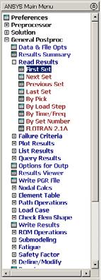
37 Example - Steps in Submodeling The process for using submodeling is as follows: Create and analyze the coarse model. Create the submodel. Perform Cut Boundary Interpolation (CBI). Analyze the submodel. Verify that the distance between the cut boundaries and the stress concentration is adequate. 73 Example CBI Steps The following tasks are involved in performing the cut boundary interpolation: 1. Identify and write the cutcut-boundary nodes 2. Restore the full set of nodes, write the database to Jobname.DB 3. To do the cut boundary interpolation restore the coarse model 4. Enter POST1 5. Point to the coarse results file 6. Read in the desired set of data from the results 74 file 37
38
39
40
41 Example - CBI Steps The following tasks are involved in performing the cut boundary interpolation: 1. Identify and write the cut-boundary nodes 2. Restore the full set of nodes, write the database to Jobname.DB 3. To do the cut boundary interpolation restore the coarse model 4. Enter POST1 5. Point to the coarse results file 6. Read in the desired set of data from the results file 7. Initiate cut-boundary interpolation 8. All interpolation work is now done 81 Example CBI: Step 2 Select Pick All 82 41
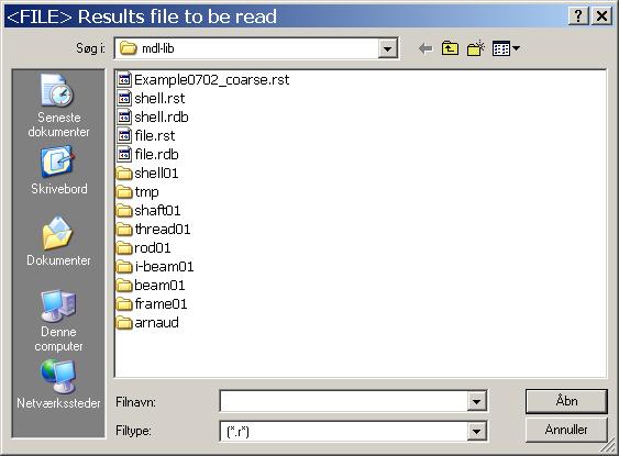
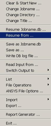
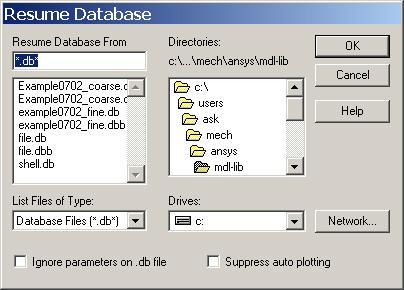
42 Example - CBI Steps The following tasks are involved in performing the cut boundary interpolation: 1. Identify and write the cut-boundary nodes 2. Restore the full set of nodes, write the database to Jobname.DB 3. To do the cut boundary interpolation restore the coarse model 4. Enter POST1 5. Point to the coarse results file 6. Read in the desired set of data from the results file 7. Initiate cut-boundary interpolation 8. All interpolation work is now done 83 Example CBI: Step 3 Enter example0702_coarse.db Press OK 84 42
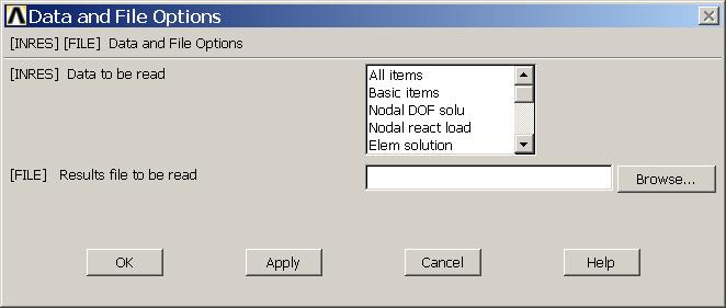
43 Example CBI: Step 3 85 Example - CBI Steps The following tasks are involved in performing the cut boundary interpolation: 1. Identify and write the cut-boundary nodes 2. Restore the full set of nodes, write the database to Jobname.DB 3. To do the cut boundary interpolation restore the coarse model 4. Enter POST1 5. Point to the coarse results file 6. Read in the desired set of data from the results file 7. Initiate cut-boundary interpolation 8. All interpolation work is now done 86 43
44


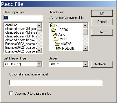
45 Example - CBI Steps The following tasks are involved in performing the cut boundary interpolation: 1. Identify and write the cut-boundary nodes 2. Restore the full set of nodes, write the database to Jobname.DB 3. To do the cut boundary interpolation restore the coarse model 4. Enter POST1 5. Point to the coarse results file 6. Read in the desired set of data from the results file 7. Initiate cutcut-boundary interpolation 8. All interpolation work is now done 89 Example CBI: Step 7 Press OK Browse to find example0702_cutboundary 90 45
46


47

48 Example Contour Plot General Postproc > Plot Results > Contour Plot > Nodal Sol Select Stress Select SX for stresses in x-direction 95 Example Contour Plot 96 48
49
50
51
52
53
54
55

56
Course in ANSYS. Example0505. ANSYS Computational Mechanics, AAU, Esbjerg
 Course in Example0505 Example Plate Objective: Compute the buckling load Tasks: How should this be modelled? Compare results with results obtained from norm calculations? Topics: Element type, Real constants,
Course in ANSYS. Example0601. ANSYS Computational Mechanics, AAU, Esbjerg
 Course in Example0601 Example Turbine Blade Example0601 2 Example Turbine Blade Objective: Solve for the temperature distribution within the 6mm thick turbine blade, with 2mm x 6mm rectangular cooling
Example Cantilever beam
 Course in ANSYS Example0300 Example Cantilever beam Objective: Compute the maximum deflection and locate point of maximum deflection Tasks: How should this be modelled? Compare results with results obtained
Course in ANSYS. Example0153. ANSYS Computational Mechanics, AAU, Esbjerg
 Course in Example0153 Example Offshore structure F Objective: Display the deflection figure and von Mises stress distribution Tasks: Import geometry from IGES. Display the deflection figure? Display the
Course in ANSYS. Example0410. ANSYS Computational Mechanics, AAU, Esbjerg
 Course in Example0410 Example Frame 2D Objective: Compute the harmonic response Tasks: Perform a modal analysis Display the mode shapes Perform a harmonic analysis Topics: Topics: Start of analysis, Element
Course in ANSYS. Example Truss 2D. Example0150
 Course in ANSYS Example0150 Example Truss 2D Objective: Compute the maximum deflection Tasks: Display the deflection figure? Topics: Topics: Start of analysis, Element type, Real constants, Material, modeling,
Course in ANSYS. Example0154. ANSYS Computational Mechanics, AAU, Esbjerg
 Course in Example0154 Example Frame 2D E = 210000N/mm 2 n = 0.3 L= 1000mm H = 1000mm a = 20mm b = 50mm c = 400mm F = 10000N I = 208333N/mm 4 Example0154 2 Example Frame 2D Objective: Compute the maximum
Course in ANSYS. Example0152. ANSYS Computational Mechanics, AAU, Esbjerg
 Course in Example0152 Example Truss 2D E = 210e09N/m 2 n = 0.3 L1 = L2 = L3 = 3.6m H = 3.118m a = b = 0.050mm F1 = 280kN F2 = 210kN F3 = 280kN F4 = 360kN Example0152 2 Example Truss 2D Objective: Compute
Exercise 1. 3-Point Bending Using the GUI and the Bottom-up-Method
 Exercise 1 3-Point Bending Using the GUI and the Bottom-up-Method Contents Learn how to... 1 Given... 2 Questions... 2 Taking advantage of symmetries... 2 A. Preprocessor (Setting up the Model)... 3 A.1
Course in ANSYS. Example0303. ANSYS Computational Mechanics, AAU, Esbjerg
 Course in Example0303 Example Gear axle 3D Objective: Compute the maximum stress von Mise Tasks: How should this be modeled? Topics: Element type, Real constants, modeling, Plot results, output graphics,
Course in ANSYS. Example0504. ANSYS Computational Mechanics, AAU, Esbjerg
 Course in Example0504 Example Cantilever beam Objective: Compute the buckling load Tasks: Display the deflection figure? Topics: Topics: Start of analysis, Element type, Real constants, Material, modeling,
NonLinear Analysis of a Cantilever Beam
 NonLinear Analysis of a Cantilever Beam Introduction This tutorial was created using ANSYS 7.0 The purpose of this tutorial is to outline the steps required to do a simple nonlinear analysis of the beam
Chapter 2. Structural Tutorial
 Chapter 2. Structural Tutorial Tutorials> Chapter 2. Structural Tutorial Static Analysis of a Corner Bracket Problem Specification Problem Description Build Geometry Define Materials Generate Mesh Apply
file://c:\documents and Settings\sala\Configuración local\temp\~hha54f.htm
 Página 1 de 26 Tutorials Chapter 2. Structural Tutorial 2.1. Static Analysis of a Corner Bracket 2.1.1. Problem Specification Applicable ANSYS Products: Level of Difficulty: Interactive Time Required:
ANSYS 5.6 Tutorials Lecture # 2 - Static Structural Analysis
 R50 ANSYS 5.6 Tutorials Lecture # 2 - Static Structural Analysis Example 1 Static Analysis of a Bracket 1. Problem Description: The objective of the problem is to demonstrate the basic ANSYS procedures
Structural static analysis - Analyzing 2D frame
 Structural static analysis - Analyzing 2D frame In this tutorial we will analyze 2D frame (see Fig.1) consisting of 2D beams with respect to resistance to two different kinds of loads: (a) the downward
Course in ANSYS. Example0500. ANSYS Computational Mechanics, AAU, Esbjerg
 Course in Example0500 Example Column beam Objective: Compute the critical buckling load and display the mode shape Tasks: Create a table and compare results with results obtained from buckling theory?
Structural static analysis - Analyzing 2D frame
 Structural static analysis - Analyzing 2D frame In this tutorial we will analyze 2D frame (see Fig.1) consisting of 2D beams with respect to resistance to two different kinds of loads: (a) the downward
ECE421: Electronics for Instrumentation
 ECE421: Electronics for Instrumentation Lecture #8: Introduction to FEA & ANSYS Mostafa Soliman, Ph.D. March 23 rd 2015 Mostafa Soliman, Ph.D. 1 Outline Introduction to Finite Element Analysis Introduction
Latch Spring. Problem:
 Problem: Shown in the figure is a 12-gauge (0.1094 in) by 3/4 in latching spring which supports a load of F = 3 lb. The inside radius of the bend is 1/8 in. Estimate the stresses at the inner and outer
Release 10. Kent L. Lawrence. Mechanical and Aerospace Engineering University of Texas at Arlington SDC PUBLICATIONS
 ANSYS Release 10 Tutorial Kent L. Lawrence Mechanical and Aerospace Engineering University of Texas at Arlington SDC PUBLICATIONS Schroff Development Corporation www.schroff.com www.schroff-europe.com
Bell Crank. Problem: Joseph Shigley and Charles Mischke. Mechanical Engineering Design 5th ed (New York: McGraw Hill, May 2002) page 87.
 page 87.") Problem: A cast-iron bell-crank lever, depicted in the figure below is acted upon by forces F 1 of 250 lb and F 2 of 333 lb. The section A-A at the central pivot has a curved inner surface with a radius
Problem: A cast-iron bell-crank lever, depicted in the figure below is acted upon by forces F 1 of 250 lb and F 2 of 333 lb. The section A-A at the central pivot has a curved inner surface with a radius
ANSYS Tutorial Release 11.0
 ANSYS Tutorial Release 11.0 Structural & Thermal Analysis Using the ANSYS Release 11.0 Environment Kent L. Lawrence Mechanical and Aerospace Engineering University of Texas at Arlington SDC PUBLICATIONS
NonLinear Materials AH-ALBERTA Web:
 NonLinear Materials Introduction This tutorial was completed using ANSYS 7.0 The purpose of the tutorial is to describe how to include material nonlinearities in an ANSYS model. For instance, the case
Two Dimensional Truss
 Two Dimensional Truss Introduction This tutorial was created using ANSYS 7.0 to solve a simple 2D Truss problem. This is the first of four introductory ANSYS tutorials. Problem Description Determine the
Instructions for Muffler Analysis
 Instructions for Muffler Analysis Part 1: Create the BEM mesh using ANSYS Specify Element Type Preprocessor > Element Type > Add/Edit/Delete Add Shell Elastic 4 Node 181 Close Specify Geometry Preprocessor
Statically Indeterminate Beam
 Problem: Using Castigliano's Theorem, determine the deflection at point A. Neglect the weight of the beam. W 1 N/m B 5 cm H 1 cm 1.35 m Overview Anticipated time to complete this tutorial: 45 minutes Tutorial
Coupled Structural/Thermal Analysis
 Coupled Structural/Thermal Analysis Introduction This tutorial was completed using ANSYS 7.0 The purpose of this tutorial is to outline a simple coupled thermal/structural analysis. A steel link, with
6. Results Combination in Hexagonal Shell
 6. Results Combination in Hexagonal Shell Applicable CivilFEM Product: All CivilFEM Products Level of Difficulty: Moderate Interactive Time Required: 0 minutes Discipline: Load combinations results Analysis
ANSYS Workbench Guide
 ANSYS Workbench Guide Introduction This document serves as a step-by-step guide for conducting a Finite Element Analysis (FEA) using ANSYS Workbench. It will cover the use of the simulation package through
Module 3: Buckling of 1D Simply Supported Beam
 Module : Buckling of 1D Simply Supported Beam Table of Contents Page Number Problem Description Theory Geometry 4 Preprocessor 7 Element Type 7 Real Constants and Material Properties 8 Meshing 9 Solution
Module 1.2: Moment of a 1D Cantilever Beam
 Module 1.: Moment of a 1D Cantilever Beam Table of Contents Page Number Problem Description Theory Geometry Preprocessor 6 Element Type 6 Real Constants and Material Properties 7 Meshing 9 Loads 10 Solution
ANSYS. Geometry. Material Properties. E=2.8E7 psi v=0.3. ansys.fem.ir Written By:Mehdi Heydarzadeh Page 1
 Attention: This tutorial is outdated, you will be redirected automatically to the new site. If you are not redirected, click this link to the confluence site. Problem Specification Geometry Material Properties
Structural modal analysis - 2D frame
 Structural modal analysis - 2D frame Determine the first six vibration characteristics, namely natural frequencies and mode shapes, of a structure depicted in Fig. 1, when Young s modulus= 27e9Pa, Poisson
ANSYS Tutorials. Table of Contents. Grady Lemoine
 ANSYS Tutorials Grady Lemoine Table of Contents Example 1: 2-D Static Stress Analysis in ANSYS...2 Example 2: 3-D Static Stress Analysis...5 Example 3: 2-D Frame With Multiple Materials and Element Types...10
Appendix B Submodeling Technique
 Appendix B Submodeling Technique 16.0 Release Introduction to ANSYS Mechanical 1 2015 ANSYS, Inc. February 27, 2015 Chapter Overview In this chapter controlling meshing operations is described. Topics:
Module 1.5: Moment Loading of a 2D Cantilever Beam
 Module 1.5: Moment Loading of a D Cantilever Beam Table of Contents Page Number Problem Description Theory Geometry 4 Preprocessor 7 Element Type 7 Real Constants and Material Properties 8 Meshing 9 Loads
COMPUTER AIDED ENGINEERING. Part-1
 COMPUTER AIDED ENGINEERING Course no. 7962 Finite Element Modelling and Simulation Finite Element Modelling and Simulation Part-1 Modeling & Simulation System A system exists and operates in time and space.
Melting Using Element Death
 Melting Using Element Death Introduction This tutorial was completed using ANSYS 7.0 The purpose of the tutorial is to outline the steps required to use element death to model melting of a material. Element
Module 1.6: Distributed Loading of a 2D Cantilever Beam
 Module 1.6: Distributed Loading of a 2D Cantilever Beam Table of Contents Page Number Problem Description 2 Theory 2 Geometry 4 Preprocessor 7 Element Type 7 Real Constants and Material Properties 8 Meshing
Linear Static Analysis of a Plate with Hole
 Fergyanto E. Gunawan (f.e.gunawan@gmail.com) Department of Mechanical Engineering Toyohashi University of Technology Objectives: Modeling a symmetric structure Bottom-up and top-down approaches in modeling
Transient Thermal Conduction Example
 Transient Thermal Conduction Example Introduction This tutorial was created using ANSYS 7.0 to solve a simple transient conduction problem. Special thanks to Jesse Arnold for the analytical solution shown
ANSYS AIM Tutorial Structural Analysis of a Plate with Hole
 ANSYS AIM Tutorial Structural Analysis of a Plate with Hole Author(s): Sebastian Vecchi, ANSYS Created using ANSYS AIM 18.1 Problem Specification Pre-Analysis & Start Up Analytical vs. Numerical Approaches
Institute of Mechatronics and Information Systems
 EXERCISE 2 Free vibrations of a beam arget Getting familiar with the fundamental issues of free vibrations analysis of elastic medium, with the use of a finite element computation system ANSYS. Program
Ansys Lab Frame Analysis
 Ansys Lab Frame Analysis Analyze the highway overpass frame shown in Figure. The main horizontal beam is W24x162 (area = 47.7 in 2, moment of inertia = 5170 in 4, height = 25 in). The inclined members
TWO-DIMENSIONAL PROBLEM OF THE THEORY OF ELASTICITY. INVESTIGATION OF STRESS CONCENTRATION FACTORS.
 Ex_1_2D Plate.doc 1 TWO-DIMENSIONAL PROBLEM OF THE THEORY OF ELASTICITY. INVESTIGATION OF STRESS CONCENTRATION FACTORS. 1. INTRODUCTION Two-dimensional problem of the theory of elasticity is a particular
Structural modal analysis - 2D frame
 Structural modal analysis - 2D frame Determine the first six vibration characteristics, namely natural frequencies and mode shapes, of a structure depicted in Fig. 1, when Young s modulus= 27e9Pa, Poisson
5. Shell Reinforcement According To Eurocode 2
 5. Shell Reinforcement According To Eurocode Applicable CivilFEM Product: All CivilFEM Products Level of Difficulty: Moderate Interactive Time Required: 5 minutes Discipline: Concrete Shell Reinforcement
A plate with a hole is subjected to tension as shown: z p = 25.0 N/mm 2
 Problem description A plate with a hole is subjected to tension as shown: z p = 25.0 N/mm 2 56 y All lengths in mm. Thickness =1mm E = 7.0 10 4 N/mm = 0.25 10 20 This is the same problem as problem 2.
ANSYS EXERCISE ANSYS 5.6 Temperature Distribution in a Turbine Blade with Cooling Channels
 I. ANSYS EXERCISE ANSYS 5.6 Temperature Distribution in a Turbine Blade with Cooling Channels Copyright 2001-2005, John R. Baker John R. Baker; phone: 270-534-3114; email: jbaker@engr.uky.edu This exercise
ANSYS Tutorial Version 6
 ANSYS Tutorial Version 6 Fracture Analysis Consultants, Inc www.fracanalysis.com Revised: November 2011 Table of Contents: 1.0 Introduction... 4 2.0 Tutorial 1: Crack Insertion and Growth in a Cube...
Lecture # 5 Modal or Dynamic Analysis of an Airplane Wing
 Lecture # 5 Modal or Dynamic Analysis of an Airplane Wing Problem Description This is a simple modal analysis of a wing of a model airplane. The wing is of uniform configuration along its length and its
Modelling and Analysis Lab (FEA)
") Channabasaveshwara Institute of Technology (Affiliated to VTU, Belagavi & Approved by AICTE, New Delhi) (NAAC Accredited & ISO 9001:2015 Certified Institution) NH 206 (B.H. Road), Gubbi, Tumakuru 572 216.
Channabasaveshwara Institute of Technology (Affiliated to VTU, Belagavi & Approved by AICTE, New Delhi) (NAAC Accredited & ISO 9001:2015 Certified Institution) NH 206 (B.H. Road), Gubbi, Tumakuru 572 216.
Institute of Mechatronics and Information Systems
 EXERCISE 4 Free vibrations of an electrical machine model Target Getting familiar with the fundamental issues of free vibrations analysis of a simplified model of an electrical machine, with the use of
FINITE ELEMENT ANALYSIS LABORATORY MANUAL ANSYS. Course Instructor: Dr. R.Ganesan
 FINITE ELEMENT ANALYSIS MECH 460 LABORATORY MANUAL ANSYS Course Instructor: Dr. R.Ganesan Prepared by A. Zabihollah Approved by Dr. R. Ganesan Winter 2007 Table of Contents 1. INTRODUCTION.3 1.1 Starting
Finite Element Course ANSYS Mechanical Tutorial Tutorial 4 Plate With a Hole
 Problem Specification Finite Element Course ANSYS Mechanical Tutorial Tutorial 4 Plate With a Hole Consider the classic example of a circular hole in a rectangular plate of constant thickness. The plate
MECH 3130: Mechanics of Materials. Fall Laboratory Manual. Volume II
 MECH 3130: Mechanics of Materials Fall 2015 Laboratory Manual Volume II Instructor Dr. Peter Schwartz Dr. Nels Madsen Lab Teaching Assistants Quang Nguyen: qzn0003@auburn.edu Abhiram Pasumarthy rzp0025@auburn.edu
Course in. FEM ANSYS Classic
 Course in Geometric modeling Modeling Programme for Lesson: Modeling considerations Element Type Real Constants Material Properties Sections Geometry/Modeling WorkPlane & Coordinate systems Keypoints Lines
CE Advanced Structural Analysis. Lab 4 SAP2000 Plane Elasticity
 Department of Civil & Geological Engineering COLLEGE OF ENGINEERING CE 463.3 Advanced Structural Analysis Lab 4 SAP2000 Plane Elasticity February 27 th, 2013 T.A: Ouafi Saha Professor: M. Boulfiza 1. Rectangular
Buckling of Euler Column
 Problem: An Euler column with one end fixed and one end free is to be made of an aluminum alloy (E = 71 GPa). The cross sectional area of the column is 600 mm and the column is.5 m long. Determine the
WORKSHOP 6.3 WELD FATIGUE USING NOMINAL STRESS METHOD. For ANSYS release 14
 WORKSHOP 6.3 WELD FATIGUE USING NOMINAL STRESS METHOD For ANSYS release 14 Objective: In this workshop, a weld fatigue analysis on a VKR-beam with a plate on top using the nominal stress method is demonstrated.
Coustyx Tutorial Indirect Model
 Coustyx Tutorial Indirect Model 1 Introduction This tutorial is created to outline the steps required to compute radiated noise from a gearbox housing using Coustyx software. Detailed steps are given on
Dhanalakshmi College Of Engineering
 Dhanalakshmi College Of Engineering Manimangalam, Tambaram, Chennai 601 301 DEPARTMENT OF MECHANICAL ENGINEERING ME 6711 SIMULATION AND ANALYSIS LABORATORY VII SEMESTER - R 2013 LABORATORY MANUAL Name
Essay 5 Tutorial for a Three-Dimensional Heat Conduction Problem Using ANSYS
 Essay 5 Tutorial for a Three-Dimensional Heat Conduction Problem Using ANSYS 5.1 Introduction The problem selected to illustrate the use of ANSYS software for a three-dimensional steadystate heat conduction
Exercise 1. 3-Point Bending Using the Static Structural Module of. Ansys Workbench 14.0
 Exercise 1 3-Point Bending Using the Static Structural Module of Contents Ansys Workbench 14.0 Learn how to...1 Given...2 Questions...2 Taking advantage of symmetries...2 A. Getting started...3 A.1 Choose
Helical Spring. Supplementary Exercise - 6. Objective: Develop model of a helical spring
 Supplementary Exercise - 6 Helical Spring Objective: Develop model of a helical spring Perform a linear analysis to obtain displacements and stresses. MSC.Patran 301 Exercise Workbook Supp6-1 Supp6-2 MSC.Patran
Module 1.3W Distributed Loading of a 1D Cantilever Beam
 Module 1.3W Distributed Loading of a 1D Cantilever Beam Table of Contents Page Number Problem Description 2 Theory 2 Workbench Analysis System 4 Engineering Data 5 Geometry 6 Model 11 Setup 13 Solution
Introduction: RS 3 Tutorial 1 Quick Start
 Introduction: RS 3 Tutorial 1 Quick Start Welcome to RS 3. This tutorial introduces some basic features of RS 3. The model analyzes the effect of tank loading on an existing sloped underground tunnel.
FINITE ELEMENT ANALYSIS OF A PLANAR TRUSS
 Problem Description: FINITE ELEMENT ANALYSIS OF A PLANAR TRUSS Instructor: Professor James Sherwood Revised: Dimitri Soteropoulos Programs Utilized: Abaqus/CAE 6.11-2 This tutorial explains how to build
Linear Buckling Analysis of a Plate
 Workshop 9 Linear Buckling Analysis of a Plate Objectives Create a geometric representation of a plate. Apply a compression load to two apposite sides of the plate. Run a linear buckling analysis. 9-1
IJMH - International Journal of Management and Humanities ISSN:
 EXPERIMENTAL STRESS ANALYSIS SPUR GEAR USING ANSYS SOFTWARE T.VADIVELU 1 (Department of Mechanical Engineering, JNTU KAKINADA, Kodad, India, vadimay28@gmail.com) Abstract Spur Gear is one of the most important
Spatial Variation of Physical Properties
 LESSON 5 Spatial Variation of Physical Properties Aluminum Steel 45 Radius 1 Radius 3 Radius 4 Objective: To model the variation of physical properties as a function of spatial coordinates. MSC/NASTRAN
1.992, 2.993, 3.04, 10.94, , Introduction to Modeling and Simulation Prof. F.-J. Ulm Spring FE Modeling Example Using ADINA
 1.992, 2.993, 3.04, 10.94, 18.996, 22.091 Introduction to Modeling and Simulation Prof. F.-J. Ulm Spring 2002 FE Modeling Example Using ADINA H Hgρ w ργ H = B = 10 m g = 9.81 m/s 2 ρ = 2400 kg/m 3 ρ w
This tutorial will take you all the steps required to import files into ABAQUS from SolidWorks
 ENGN 1750: Advanced Mechanics of Solids ABAQUS CAD INTERFACE TUTORIAL School of Engineering Brown University This tutorial will take you all the steps required to import files into ABAQUS from SolidWorks
Problem description. It is desired to analyze the cracked body shown using a 3D finite element mesh: Top view. 50 radius. Material properties:
 Problem description It is desired to analyze the cracked body shown using a 3D finite element mesh: Top view 30 50 radius 30 Material properties: 5 2 E = 2.07 10 N/mm = 0.29 All dimensions in mm Crack
Abaqus CAE Tutorial 1: 2D Plane Truss
 ENGI 7706/7934: Finite Element Analysis Abaqus CAE Tutorial 1: 2D Plane Truss Lab TA: Xiaotong Huo EN 3029B xh0381@mun.ca Download link for Abaqus student edition: http://academy.3ds.com/software/simulia/abaqus-student-edition/
Spatial Variation of Physical Properties
 LESSON 13 Spatial Variation of Physical Properties Aluminum Steel 45 Radius 1 Radius 3 Radius 4 Objective: To model the variation of physical properties as a function of spatial coordinates. PATRAN301ExericseWorkbook-Release7.5
Aufgabe 1: Dreipunktbiegung mit ANSYS Workbench
 Aufgabe 1: Dreipunktbiegung mit ANSYS Workbench Contents Beam under 3-Pt Bending [Balken unter 3-Pkt-Biegung]... 2 Taking advantage of symmetries... 3 Starting and Configuring ANSYS Workbench... 4 A. Pre-Processing:
TUTORIAL 7: Stress Concentrations and Elastic-Plastic (Yielding) Material Behavior Initial Project Space Setup Static Structural ANSYS ZX Plane
 Material Behavior Initial Project Space Setup Static Structural ANSYS ZX Plane") TUTORIAL 7: Stress Concentrations and Elastic-Plastic (Yielding) Material Behavior In this tutorial you will learn how to recognize and deal with a common modeling issues involving stress concentrations
TUTORIAL 7: Stress Concentrations and Elastic-Plastic (Yielding) Material Behavior In this tutorial you will learn how to recognize and deal with a common modeling issues involving stress concentrations
Finite Element Method. Chapter 7. Practical considerations in FEM modeling
 Finite Element Method Chapter 7 Practical considerations in FEM modeling Finite Element Modeling General Consideration The following are some of the difficult tasks (or decisions) that face the engineer
A plate with a hole is subjected to tension as shown: p = 25.0 N/mm 2. Region to mesh
 Problem description A plate with a hole is subjected to tension as shown: y p = 25. N/mm 2 Region to mesh 56 x All lengths in mm. Thickness=1mm 4 E = 7. 1 N/mm =.25 1 2 This is the same model and loading
Outline. 3 Linear Analysis 3.1 Analysis commands 3.2 Results. Box Girder Bridge 2/28
 ANALYS: linear static. CONSTR: suppor. ELEMEN: bar hx24l reinfo solid tp18l. LOAD: elemen face force prestr reinfo weight. MATERI: elasti isotro. OPTION: direct. POST: binary ndiana. PRE: dianai. RESULT:
Elastic Analysis of a Deep Beam with Web Opening
 Elastic Analysis of a Deep Beam with Web Opening Outline 1 Description 2 Finite Element Model 2.1 Units 2.2 Geometry definition 2.3 Properties 2.4 Boundary conditions 2.4.1 Constraints 2.4.2 Vertical load
Module 1.7: Point Loading of a 3D Cantilever Beam
 Module 1.7: Point Loading of a D Cantilever Beam Table of Contents Page Number Problem Description Theory Geometry 4 Preprocessor 6 Element Type 6 Material Properties 7 Meshing 8 Loads 9 Solution 15 General
ENGINEERING TRIPOS PART IIA FINITE ELEMENT METHOD
 ENGINEERING TRIPOS PART IIA LOCATION: DPO EXPERIMENT 3D7 FINITE ELEMENT METHOD Those who have performed the 3C7 experiment should bring the write-up along to this laboratory Objectives Show that the accuracy
Chapter 3 Analysis of Original Steel Post
 Chapter 3. Analysis of original steel post 35 Chapter 3 Analysis of Original Steel Post This type of post is a real functioning structure. It is in service throughout the rail network of Spain as part
Appendix B: Creating and Analyzing a Simple Model in Abaqus/CAE
 Getting Started with Abaqus: Interactive Edition Appendix B: Creating and Analyzing a Simple Model in Abaqus/CAE The following section is a basic tutorial for the experienced Abaqus user. It leads you
Deep Beam With Web Opening
 Deep Beam With Web Opening Name: Path: Keywords: DeepBeamWithWebOpening/deepbeam /Examples//DeepBeamWithWebOpening/deepbeam analys: linear static. constr: suppor. elemen: cq16m ct12m pstres. load: force
General modeling guidelines
 General modeling guidelines Some quotes from industry FEA experts: Finite element analysis is a very powerful tool with which to design products of superior quality. Like all tools, it can be used properly,
Interface with FE programs
 Page 1 of 47 Interdisciplinary > RFlex > Flexible body Interface Interface with FE programs RecurDyn/RFlex can import FE model from ANSYS, NX/NASTRAN, MSC/NASTRAN and I-DEAS. Figure 1 RecurDyn/RFlex Interface
Chapter 3. Thermal Tutorial
 Chapter 3. Thermal Tutorial Tutorials> Chapter 3. Thermal Tutorial Solidification of a Casting Problem Specification Problem Description Prepare for a Thermal Analysis Input Geometry Define Materials Generate
Computational Simulation of Cylindrical Pressure Loading
 Computational Simulation of Cylindrical Pressure Loading MEG 795 Special Topics: Energy Methods II Presented By: Nallani Gopi Nov 20, 2003 Department of Mechanical Engineering University of Nevada,Las
Stresses in an Elliptical Beam
 Problem: An offset tensile link is shaped to clear an obstruction with a geometry as shown in the figure. The cross section at the critical location is elliptical, with a major axis of 4 in and a minor
Finite Element Course ANSYS Mechanical Tutorial Tutorial 3 Cantilever Beam
 Problem Specification Finite Element Course ANSYS Mechanical Tutorial Tutorial 3 Cantilever Beam Consider the beam in the figure below. It is clamped on the left side and has a point force of 8kN acting
Exercise 1: 3-Pt Bending using ANSYS Workbench
 Exercise 1: 3-Pt Bending using ANSYS Workbench Contents Starting and Configuring ANSYS Workbench... 2 1. Starting Windows on the MAC... 2 2. Login into Windows... 2 3. Start ANSYS Workbench... 2 4. Configuring
TRINITAS. a Finite Element stand-alone tool for Conceptual design, Optimization and General finite element analysis. Introductional Manual
 TRINITAS a Finite Element stand-alone tool for Conceptual design, Optimization and General finite element analysis Introductional Manual Bo Torstenfelt Contents 1 Introduction 1 2 Starting the Program
WORKSHOP 6.4 WELD FATIGUE USING HOT SPOT STRESS METHOD. For ANSYS release 14
 WORKSHOP 6.4 WELD FATIGUE USING HOT SPOT STRESS METHOD For ANSYS release 14 Objective: In this workshop, a weld fatigue analysis on a VKR-beam with a plate on top using the nominal stress method is demonstrated.
ANSYS Mechanical APDL Tutorials
 ANSYS Mechanical APDL Tutorials ANSYS, Inc. Southpointe 275 Technology Drive Canonsburg, PA 15317 ansysinfo@ansys.com http://www.ansys.com (T) 724-746-3304 (F) 724-514-9494 Release 13.0 November 2010 ANSYS,
Practical modeling of diaphragm walls and foundation rafts with piles part I
 Practical modeling of diaphragm walls and foundation rafts with piles part I FE mesh This example concerns modeling of a deep excavation protected by concrete wall an then by a construction of foundation
Abaqus/CAE (ver. 6.11) Nonlinear Buckling Tutorial
 Nonlinear Buckling Tutorial") Abaqus/CAE (ver. 6.11) Nonlinear Buckling Tutorial Problem Description This is the NAFEMS 1 proposed benchmark (Lee s frame buckling) problem. The applied load is based on the normalized (EI/L 2 ) value
Abaqus/CAE (ver. 6.11) Nonlinear Buckling Tutorial Problem Description This is the NAFEMS 1 proposed benchmark (Lee s frame buckling) problem. The applied load is based on the normalized (EI/L 2 ) value