Register Transfer Level in Verilog: Part I
|
|
|
- Lindsey Holland
- 6 years ago
- Views:
Transcription
, Ph. D. Department of Computer Science National Chiao Tung University Taiwan, R.O.C. Fall, 2014 ldvan@cs.")
1 Source: M. Morris Mano and Michael D. Ciletti, Digital Design, 4rd Edition, 2007, Prentice Hall. Register Transfer Level in Verilog: Part I Lan-Da Van ( 范倫達 ), Ph. D. Department of Computer Science National Chiao Tung University Taiwan, R.O.C. Fall, 2014 ldvan@cs.nctu.edu.tw
2 Introduction A digital system is a sequential logic system constructed with flip-flops and gates. To specify a large digital system with a state table is very difficult. Modular subsystems Registers, decoders, multiplexers, arithmetic elements and control logic. They are interconnected with datapaths and control signals. A digital system is represented at the register transfer level (RTL) when it is specified by the following three components: The set of registers in the system. The operations that are performed on the data stored in the registers. The control that supervises the sequence of operations in the system. 2
3 Statement R2 R1 denotes a transfer of the contents of register R1 into register R2. A conditional statement governing a register transfer operation is symbolized with an if-then statement such as If (T1 =1) then (R2 R1) where T1 is a control signal generated in the control section. R1 R1 + R2 Add contents of R2 to R1 R3 R3 + 1 Increment R3 by 1 R4 shr R4 Shift right R4 R5 0 Clear R5 to 0 3
4 Type of Operations Most Often Encountered in Digital System Digital Circuit Lab Transfer operations, which transfer data from one register to anther. Arithmetic operations, which perform arithmetic on data in registers. Logic operations, which perform bit manipulation of nonnumeric data in registers. Shift operations, which shift data between registers. 4
5 Register Transfer Level in HDL In Verilog, descriptions of RTL operations use a combination of behavioral and dataflow constructs and are employed to specify register operations procedural assignment statements within an edge-sensitive cycle behavior combinational logic functions continuous assignment statement or by procedural assignment statements within a level-sensitive cycle behavior 5
6 Register Transfer Level in HDL The following examples show the various ways to specify a register transfer operation in Verilog: (a) assign S = A + B; //continuous assignment for addition operation (b) (A, B) //level-sensitive cyclic behavior S = A + B; //combinational logic for addition operation (c) (negedge clock) //edge-sensitive cyclic behavior begin RA < = RA + RB; //nonblocking procedural assignment for addition RD < = RA; //register transfer operation end The target operand in a continuous assignment statement (assign S = A + B) cannot be a register data type, but must be a type of net, for example, wire. There are two kinds of procedural assignments: blocking and nonbolcking. 6
7 HDL Operators 7
8 HDL Operators
9 HDL Operators The exponentiation operator (**) was added to the language in 2001 and forms a doubleprecision floating-point value from a base and exponent having a real, integer, or signed value. Two types of logic operators for binary words: bitwise a bit-by-bit operation on two vector operands to from a vector result. reduction acting on a single operand and producing a scalar (one-bit) result. the reduction NOR (~ ) results in 0 with operand and and in 1 with operand Negation: bitwise only. 9
10 HDL Operators The logical and relational operators are used to form Boolean expressions and can take variables or expressions as operands. An operand that is variable evaluates to 0 if the value of the variable is equal to zero and to 1 if the value is not equal to zero. 10
11 HDL Operators For example, if A =1010, B =0000, then A has the Boolean value 1, B has Boolean value 0. Results of other operation with these value: A && B = 0 A B = 1 // logical AND // logical OR!A = 0 // logical complement!b = 1 // logical complement (A > B) = 1 // is greater than (A == B) = 0 // identity (equality) 11
12 HDL Operators 12
13 repeat loop Loop Statements forever loop initial initial begin begin clock =1'b0; clock =1'b0; repeat (16) forever #5 clock =~clock; #10 clock =~clock; end end while loop for loop integer count; for (j =0; j < 8; j = j + 1) initial begin begin //procedural statement go here count =0; end while (count < 64) #5 count = count + 1; end 13
14 Loop Statements Although it is possible to use a reg variable to index a loop, sometimes it is more convenient to declare an integer variable, rather than a reg, for counting purposes. Variables declared as data type reg are stored as unsigned numbers. Those declared as data type integer are stored as signed numbers in 2 scomplement format. The default width of an integer is a minimum of 32 bits. 14
15 Loop Statements HDL Example 8.1 // Description of 2 4 decoder using a for loop statement module decoder (IN, Y); input [1: 0] IN; // Two binary inputs output [3: 0] Y; // Four binary outputs reg [3: 0] Y; integer k; // Control (index) variable for loop (IN) for (k = 0; k <= 3; k = k + 1) if (IN == k) Y[k] = 1; else Y[k] = 0; endmodule if (IN == 00) Y[0] = 1; else Y[k] = 0; if (IN == 01) Y[1] = 1; else Y[k] = 0; if (IN == 10) Y[2] = 1; else Y[k] = 0; if (IN == 11) Y[3] = 1; else Y[k] = 0; 15
16 Logic Synthesis Logic synthesis is the automatic process by which a computer-based program (i.e., a synthesis tool) transforms an HDL model of a logic circuit into an optimized netlist of gates... The types of ICs that implement the design may be: an application-specific integrated circuit (ASIC), a programmable logic device (PLD), a field-programmable gate array (FPGA). Logic synthesis is widely used in industry to design and implement large circuits efficiently, correctly, and rapidly. 16
17 Logic Synthesis The continuous assignment (assign) statement is used to describe combinational circuits. (+) a binary adder with full-adder circuits. ( ) a gate-level subtractor consisting of full adders and exclusive-or gates (Fig. 4.13). A statement with a conditional operator such as assign Y = S? In_1 : In_0; translates into a two-to-one-line multiplexer with control input S and data input In_1 and In_0. 17
18 Logic Synthesis A cyclic behavior (always...) may imply a combinational or sequential circuit, depending on whether the event control expression is level sensitive or edge sensitive. For example, (In_1 or In_0 or S) if (S) Y = In _ 1; else Y = In _ 0; translates into a two-to-one-line multiplexer. An edge-sensitive cyclic behavior (e.g., (posedge clock)) specifies a synchronous (clocked) sequential circuit. Examples of such circuits are registers and counters. 18
19 Logic Synthesis A sequential circuit description with a case statement translates into a control circuit with D flip-flops and gates that form the inputs to the flip-flops. each statement a gate/flip-flop circuit For synthesizable sequential circuits, the event control expression must be sensitive to the positive or negative edge of the clock (synchronizing signal), but not to both. 19

20 Fig. 8.1 A simplified flowchart for HDLbased modeling, verification, and synthesis 20
21 Algorithmic State Machines (ASMs) Digital Circuit Lab The logic design of digital system can be divided into two distinct parts. One is concerned with the design of the digital circuits that perform the data-processing operations. The other is concerned with the design of the control circuits that determine the sequence in which the various actions are performed. 21
22 Algorithmic State Machines (ASMs) The control logic that generates the signals for sequencing the operations in the data path unit is a finite state machine (FSM). A flowchart that has been developed specifically to define digital hardware algorithm is called an algorithmic state machine (ASM) chart. The ASM chart is composed of three basic elements: State box Decision box Conditional box They connected by directed edges indicating the sequential precedence and evolution of the states as the machine operates. 22

23 ASM Chart State Box FIGURE 8.3 ASM chart state box FIGURE 8.4 ASM chart decision box 23

24 ASM Chart Conditional Box Digital Circuit Lab 24

25 ASM block FIGURE 8.6 ASM block 25
26 Simplifications FIGURE 8.7 State diagram equivalent to the ASM chart of Fig
27 Timing Considerations The timing for all register and flip-flop in digital system is controlled by a master-clock generator. FIGURE 8.8 Transition between states 27
28 ASMD Chart Contrasted between Algorithmic State Machine and Datapath (ASMD) charts & ASM charts. An ASMD chart does not list register operations within a state box. The edges of an ASMD charts are annotated with register operations that are concurrent with the state transition indicated by the edge. An ASMD chart includes conditional boxes identifying the signals which control the register operations that annotate the edges of the chart. An ASMD chart associates register operations with state transitions rather than with state. 28
29 Three-step To Design an ASMD Chart Step 1: Form an ASM chart displaying only how the inputs to the controller determine its state transitions. Step 2: Convert the ASM chart to an ASMD chart by annotating the edges of ASM chart to indicate to the concurrent register operations of the datapath unit. Step 3: Modify the ASMD chart to identify the control signals that are generated by the controller and use the indicated register operations in the datapath unit. 29
30 Design Example Block diagram: A: a 4-bit binary counter E and F: JK flip-flops Sequence of operations: If A 2 = 0, E is cleared to 0 and the count continues. If A 2 = 1, E is set to 1; then if A 3 = 0, then the count continues, but if A 3 = 1, F is set to 1 on the next clock pulse and the system stops counting. Then, if Start = 0, the system remains in the initial state, but if Start = 1, the operation cycle repeats. 30
31 Design Example 31
32 Design Example 32
33 Design Example Datapath and controller 33
34 Design Example (state diagram) (ASMD chart) 34
35 Design Example encoding 35
36 Design Example By inspection: Sequence register & decoder (p. 390) DG0 = Start S_idle + S_1 DG1 = S_1 A2 A3 = 36
37 Design Example By inspection: (State 10 is not used) set_e = S_1 A2 clr_e = S_1 A2' set_f = S_2 = G 1 _ clr_a_f = Start S_idle = Start G 0 incr_a = S_1 37
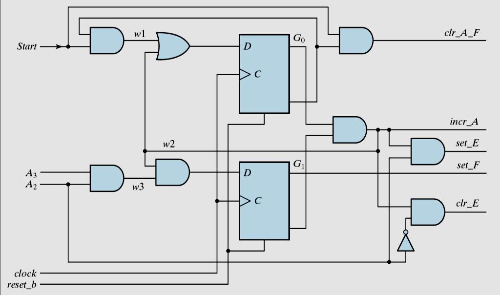
38 logic diagram of control unit Design Example set_e = S_1 A2 clr_e = S_1 A2' set_f = S_2 = G 1 clr_a_f = Start S_idle = Start G 0 incr_a = S_1 _? S_idle S_1 S_2 38
39 HDL Description of Design Example Structural sufficient experience The lowest and most detailed level Specified in terms of physical components and their interconnection RTL Imply a certain hardware configuration Specified in terms of the registers, operations performed, and control that sequences the operations. Algorithmic-based behavioral The most abstract Most appropriate for simulating complex systems to verify design ideas and explore tradeoffs Digital Circuit Lab 39
40 RTL Description The manual method of design developed A block diagram (Fig. 8.9(a)) showing the interface between the datapath and the controller. An ASMD chart for the system. (Fig. 8.9(d)) The logic equations for the inputs to the flip-flops of the controller. A circuit that implements the controller (Fig. 8.12). In contrast, an RTL model describes (1) state transitions of the controller and (2) operations of the datapath as a step towards automatically synthesizing the circuit that implements them. 40
41 RTL Description 41
42 RTL Description (forget to make an assignment is OK) (2 bx) (one of the above three not detected) 42
43 RTL Description 43
44 RTL Description 44
45 Testing the Design Description 45
46 Testing the Design Description 46
47 Testing the Design Description (in groups) (recommended) (Table 8.3) 47
48 Structural Description HDL Example 8.4 presents the structural description of the design example. It consists of a nested hierarchy of modules and gates describing: The top-level module, Design_example_STR The modules describing the controller and the datapath The modules describing the flip-flops and counters Gates implementing the logic of controller 48
49 Structural Description The top-level module (see Fig. 8.10) encapsulates the entire design by: Instantiating the controller and the datapath modules Declaring the primary (external) input signals Declaring the output signals Declaring the control signals generated by the controller and connected to the datapath unit Declaring the status signals generated by the datapath unit and connected to the controller 49

50 HDL Example
51 51
52 52
53 53
54 54
RTL Design (Using ASM/SM Chart)
") Digital Circuit Design and Language RTL Design (Using ASM/SM Chart) Chang, Ik Joon Kyunghee University Process of Logic Simulation and Synthesis Design Entry HDL Description Logic Simulation Functional
Digital Circuit Design and Language RTL Design (Using ASM/SM Chart) Chang, Ik Joon Kyunghee University Process of Logic Simulation and Synthesis Design Entry HDL Description Logic Simulation Functional
Register Transfer Level Design. Topics. Register Transfer Level Notation. Chapter 8 Steve Oldridge Dr. Sidney Fels. A Circuit is described as:
 Register Transfer Level Design Chapter 8 Steve Oldridge Dr. Sidney Fels Topics RTL Notation RTL in HDL Algorithmic State Machines Sequential Binary Multiplier Control Logic HDL Design with Multiplexors
Verilog Behavioral Modeling
 Verilog Behavioral Modeling Lan-Da Van ( 范倫達 ), Ph. D. Department of Computer Science National Chiao Tung University Taiwan, R.O.C. Spring, 2017 ldvan@cs.nctu.edu.tw http://www.cs.nctu.edu.tw/~ldvan/ Source:
Verilog Dataflow Modeling
 Verilog Dataflow Modeling Lan-Da Van ( 范倫達 ), Ph. D. Department of Computer Science National Chiao Tung University Taiwan, R.O.C. Spring, 2017 ldvan@cs.nctu.edu.tw http://www.cs.nctu.edu.tw/~ldvan/ Source:
FPGA Design Challenge :Techkriti 14 Digital Design using Verilog Part 1
 FPGA Design Challenge :Techkriti 14 Digital Design using Verilog Part 1 Anurag Dwivedi Digital Design : Bottom Up Approach Basic Block - Gates Digital Design : Bottom Up Approach Gates -> Flip Flops Digital
Verilog for Combinational Circuits
 Verilog for Combinational Circuits Lan-Da Van ( 范倫達 ), Ph. D. Department of Computer Science National Chiao Tung University Taiwan, R.O.C. Fall, 2014 ldvan@cs.nctu.edu.tw http://www.cs.nctu.edu.tw/~ldvan/
EN164: Design of Computing Systems Lecture 06: Lab Foundations / Verilog 2
 EN164: Design of Computing Systems Lecture 06: Lab Foundations / Verilog 2 Professor Sherief Reda http://scaleenginbrownedu Electrical Sciences and Computer Engineering School of Engineering Brown University
Hardware Description Languages (HDLs) Verilog
 Verilog") Hardware Description Languages (HDLs) Verilog Material from Mano & Ciletti book By Kurtulus KULLU Ankara University What are HDLs? A Hardware Description Language resembles a programming language specifically
Hardware Description Languages (HDLs) Verilog Material from Mano & Ciletti book By Kurtulus KULLU Ankara University What are HDLs? A Hardware Description Language resembles a programming language specifically
register:a group of binary cells suitable for holding binary information flip-flops + gates
 9 차시 1 Ch. 6 Registers and Counters 6.1 Registers register:a group of binary cells suitable for holding binary information flip-flops + gates control when and how new information is transferred into the
Verilog for High Performance
 Verilog for High Performance Course Description This course provides all necessary theoretical and practical know-how to write synthesizable HDL code through Verilog standard language. The course goes
Synthesis of Combinational and Sequential Circuits with Verilog
 Synthesis of Combinational and Sequential Circuits with Verilog What is Verilog? Hardware description language: Are used to describe digital system in text form Used for modeling, simulation, design Two
EN2911X: Reconfigurable Computing Lecture 05: Verilog (2)
") EN2911X: Lecture 05: Verilog (2) Prof. Sherief Reda Division of Engineering, Brown University Fall 09 http://scale.engin.brown.edu Dataflow modeling Module is designed by specifying the data flow, where
EN2911X: Lecture 05: Verilog (2) Prof. Sherief Reda Division of Engineering, Brown University Fall 09 http://scale.engin.brown.edu Dataflow modeling Module is designed by specifying the data flow, where
Register Transfer Level
 Register Transfer Level Something between the logic level and the architecture level A convenient way to describe synchronous sequential systems State diagrams for pros Hierarchy of Designs The design
Verilog Fundamentals. Shubham Singh. Junior Undergrad. Electrical Engineering
 Verilog Fundamentals Shubham Singh Junior Undergrad. Electrical Engineering VERILOG FUNDAMENTALS HDLs HISTORY HOW FPGA & VERILOG ARE RELATED CODING IN VERILOG HDLs HISTORY HDL HARDWARE DESCRIPTION LANGUAGE
Verilog HDL. A Guide to Digital Design and Synthesis. Samir Palnitkar. SunSoft Press A Prentice Hall Title
 Verilog HDL A Guide to Digital Design and Synthesis Samir Palnitkar SunSoft Press A Prentice Hall Title Table of Contents About the Author Foreword Preface Acknowledgments v xxxi xxxiii xxxvii Part 1:
ECE 2300 Digital Logic & Computer Organization. More Sequential Logic Verilog
 ECE 2300 Digital Logic & Computer Organization Spring 2018 More Sequential Logic Verilog Lecture 7: 1 Announcements HW3 will be posted tonight Prelim 1 Thursday March 1, in class Coverage: Lectures 1~7
Contents. Appendix D Verilog Summary Page 1 of 16
 Appix D Verilog Summary Page 1 of 16 Contents Appix D Verilog Summary... 2 D.1 Basic Language Elements... 2 D.1.1 Keywords... 2 D.1.2 Comments... 2 D.1.3 Identifiers... 2 D.1.4 Numbers and Strings... 3
Digital Design with FPGAs. By Neeraj Kulkarni
 Digital Design with FPGAs By Neeraj Kulkarni Some Basic Electronics Basic Elements: Gates: And, Or, Nor, Nand, Xor.. Memory elements: Flip Flops, Registers.. Techniques to design a circuit using basic
CHAPTER - 2 : DESIGN OF ARITHMETIC CIRCUITS
 Contents i SYLLABUS osmania university UNIT - I CHAPTER - 1 : BASIC VERILOG HDL Introduction to HDLs, Overview of Digital Design With Verilog HDL, Basic Concepts, Data Types, System Tasks and Compiler
Combinational Logic II
 Combinational Logic II Ranga Rodrigo July 26, 2009 1 Binary Adder-Subtractor Digital computers perform variety of information processing tasks. Among the functions encountered are the various arithmetic
ECEN 468 Advanced Logic Design
 ECEN 468 Advanced Logic Design Lecture 26: Verilog Operators ECEN 468 Lecture 26 Operators Operator Number of Operands Result Arithmetic 2 Binary word Bitwise 2 Binary word Reduction 1 Bit Logical 2 Boolean
Verilog introduction. Embedded and Ambient Systems Lab
 Verilog introduction Embedded and Ambient Systems Lab Purpose of HDL languages Modeling hardware behavior Large part of these languages can only be used for simulation, not for hardware generation (synthesis)
ECE 4514 Digital Design II. Spring Lecture 7: Dataflow Modeling
 ECE 4514 Digital Design II Lecture 7: Dataflow Modeling A language Lecture Today's topic Dataflow Modeling input input input module output output Model with submodules and gates = Structural Model with
Verilog Module 1 Introduction and Combinational Logic
 Verilog Module 1 Introduction and Combinational Logic Jim Duckworth ECE Department, WPI 1 Module 1 Verilog background 1983: Gateway Design Automation released Verilog HDL Verilog and simulator 1985: Verilog
Synthesis of Language Constructs. 5/10/04 & 5/13/04 Hardware Description Languages and Synthesis
 Synthesis of Language Constructs 1 Nets Nets declared to be input or output ports are retained Internal nets may be eliminated due to logic optimization User may force a net to exist trireg, tri0, tri1
Verilog. What is Verilog? VHDL vs. Verilog. Hardware description language: Two major languages. Many EDA tools support HDL-based design
 Verilog What is Verilog? Hardware description language: Are used to describe digital system in text form Used for modeling, simulation, design Two major languages Verilog (IEEE 1364), latest version is
Introduction. Why Use HDL? Simulation output. Explanation
 Introduction Verilog HDL is a Hardware Description Language (HDL) HDL is a language used to describe a digital system, for example, a computer or a component of a computer. Most popular HDLs are VHDL and
IT T35 Digital system desigm y - ii /s - iii
 UNIT - V Introduction to Verilog Hardware Description Language Introduction HDL for combinational circuits Sequential circuits Registers and counters HDL description for binary multiplier. 5.1 INTRODUCTION
RIZALAFANDE CHE ISMAIL TKT. 3, BLOK A, PPK MIKRO-e KOMPLEKS PENGAJIAN KUKUM. SYNTHESIS OF COMBINATIONAL LOGIC (Chapter 8)
") RIZALAFANDE CHE ISMAIL TKT. 3, BLOK A, PPK MIKRO-e KOMPLEKS PENGAJIAN KUKUM SYNTHESIS OF COMBINATIONAL LOGIC (Chapter 8) HDL-BASED SYNTHESIS Modern ASIC design use HDL together with synthesis tool to create
RIZALAFANDE CHE ISMAIL TKT. 3, BLOK A, PPK MIKRO-e KOMPLEKS PENGAJIAN KUKUM SYNTHESIS OF COMBINATIONAL LOGIC (Chapter 8) HDL-BASED SYNTHESIS Modern ASIC design use HDL together with synthesis tool to create
CSE140L: Components and Design Techniques for Digital Systems Lab
 CSE140L: Components and Design Techniques for Digital Systems Lab Tajana Simunic Rosing Source: Vahid, Katz, Culler 1 Announcements & Outline Lab 4 due; demo signup times listed on the cse140l site Check
INSTITUTE OF AERONAUTICAL ENGINEERING Dundigal, Hyderabad ELECTRONICS AND COMMUNICATIONS ENGINEERING
 INSTITUTE OF AERONAUTICAL ENGINEERING Dundigal, Hyderabad - 00 0 ELECTRONICS AND COMMUNICATIONS ENGINEERING QUESTION BANK Course Name : DIGITAL DESIGN USING VERILOG HDL Course Code : A00 Class : II - B.
Lecture 32: SystemVerilog
 Lecture 32: SystemVerilog Outline SystemVerilog module adder(input logic [31:0] a, input logic [31:0] b, output logic [31:0] y); assign y = a + b; Note that the inputs and outputs are 32-bit busses. 17:
structure syntax different levels of abstraction
 This and the next lectures are about Verilog HDL, which, together with another language VHDL, are the most popular hardware languages used in industry. Verilog is only a tool; this course is about digital
Here is a list of lecture objectives. They are provided for you to reflect on what you are supposed to learn, rather than an introduction to this
 This and the next lectures are about Verilog HDL, which, together with another language VHDL, are the most popular hardware languages used in industry. Verilog is only a tool; this course is about digital
EEL 4783: HDL in Digital System Design
 EEL 4783: HDL in Digital System Design Lecture 15: Logic Synthesis with Verilog Prof. Mingjie Lin 1 Verilog Synthesis Synthesis vs. Compilation Descriptions mapped to hardware Verilog design patterns for
St.MARTIN S ENGINEERING COLLEGE Dhulapally, Secunderabad
 St.MARTIN S ENGINEERING COLLEGE Dhulapally, Secunderabad-500 014 Subject: Digital Design Using Verilog Hdl Class : ECE-II Group A (Short Answer Questions) UNIT-I 1 Define verilog HDL? 2 List levels of
Verilog. Verilog for Synthesis
 Verilog Verilog for Synthesis 1 Verilog background 1983: Gateway Design Automation released Verilog HDL Verilog and simulator 1985: Verilog enhanced version Verilog-XL 1987: Verilog-XL becoming more popular
CSE140L: Components and Design
 CSE140L: Components and Design Techniques for Digital Systems Lab Tajana Simunic Rosing Source: Vahid, Katz, Culler 1 Grade distribution: 70% Labs 35% Lab 4 30% Lab 3 20% Lab 2 15% Lab 1 30% Final exam
Synthesizable Verilog
 Synthesizable Verilog Courtesy of Dr. Edwards@Columbia, and Dr. Franzon@NCSU http://csce.uark.edu +1 (479) 575-6043 yrpeng@uark.edu Design Methodology Structure and Function (Behavior) of a Design HDL
Lecture #2: Verilog HDL
 Lecture #2: Verilog HDL Paul Hartke Phartke@stanford.edu Stanford EE183 April 8, 2002 EE183 Design Process Understand problem and generate block diagram of solution Code block diagram in verilog HDL Synthesize
EECS150 - Digital Design Lecture 5 - Verilog Logic Synthesis
 EECS150 - Digital Design Lecture 5 - Verilog Logic Synthesis Jan 31, 2012 John Wawrzynek Spring 2012 EECS150 - Lec05-verilog_synth Page 1 Outline Quick review of essentials of state elements Finite State
MLR Institute of Technology
 MLR Institute of Technology Laxma Reddy Avenue, Dundigal, Quthbullapur (M), Hyderabad 500 043 Course Name Course Code Class Branch ELECTRONICS AND COMMUNICATIONS ENGINEERING QUESTION BANK : DIGITAL DESIGN
Synthesis vs. Compilation Descriptions mapped to hardware Verilog design patterns for best synthesis. Spring 2007 Lec #8 -- HW Synthesis 1
 Verilog Synthesis Synthesis vs. Compilation Descriptions mapped to hardware Verilog design patterns for best synthesis Spring 2007 Lec #8 -- HW Synthesis 1 Logic Synthesis Verilog and VHDL started out
CAD for VLSI Design - I. Lecture 21 V. Kamakoti and Shankar Balachandran
 CAD for VLSI Design - I Lecture 21 V. Kamakoti and Shankar Balachandran Overview of this Lecture Understanding the process of Logic synthesis Logic Synthesis of HDL constructs Logic Synthesis What is this?
VHDL for Synthesis. Course Description. Course Duration. Goals
 VHDL for Synthesis Course Description This course provides all necessary theoretical and practical know how to write an efficient synthesizable HDL code through VHDL standard language. The course goes
Hardware Design Environments. Dr. Mahdi Abbasi Computer Engineering Department Bu-Ali Sina University
 Hardware Design Environments Dr. Mahdi Abbasi Computer Engineering Department Bu-Ali Sina University Outline Welcome to COE 405 Digital System Design Design Domains and Levels of Abstractions Synthesis
Digital Circuit Design and Language. Datapath Design. Chang, Ik Joon Kyunghee University
 Digital Circuit Design and Language Datapath Design Chang, Ik Joon Kyunghee University Typical Synchronous Design + Control Section : Finite State Machine + Data Section: Adder, Multiplier, Shift Register
Date Performed: Marks Obtained: /10. Group Members (ID):. Experiment # 11. Introduction to Verilog II Sequential Circuits
:. Experiment # 11. Introduction to Verilog II Sequential Circuits") Name: Instructor: Engr. Date Performed: Marks Obtained: /10 Group Members (ID):. Checked By: Date: Experiment # 11 Introduction to Verilog II Sequential Circuits OBJECTIVES: To understand the concepts
Name: Instructor: Engr. Date Performed: Marks Obtained: /10 Group Members (ID):. Checked By: Date: Experiment # 11 Introduction to Verilog II Sequential Circuits OBJECTIVES: To understand the concepts
Verilog for Synthesis Ing. Pullini Antonio
 Verilog for Synthesis Ing. Pullini Antonio antonio.pullini@epfl.ch Outline Introduction to Verilog HDL Describing combinational logic Inference of basic combinational blocks Describing sequential circuits
Introduction to Verilog
 Introduction to Verilog Synthesis and HDLs Verilog: The Module Continuous (Dataflow) Assignment Gate Level Description Procedural Assignment with always Verilog Registers Mix-and-Match Assignments The
Nikhil Gupta. FPGA Challenge Takneek 2012
 Nikhil Gupta FPGA Challenge Takneek 2012 RECAP FPGA Field Programmable Gate Array Matrix of logic gates Can be configured in any way by the user Codes for FPGA are executed in parallel Configured using
Digital Design Using Digilent FPGA Boards -- Verilog / Active-HDL Edition
 Digital Design Using Digilent FPGA Boards -- Verilog / Active-HDL Edition Table of Contents 1. Introduction to Digital Logic 1 1.1 Background 1 1.2 Digital Logic 5 1.3 Verilog 8 2. Basic Logic Gates 9
EN2911X: Reconfigurable Computing Topic 02: Hardware Definition Languages
 EN2911X: Reconfigurable Computing Topic 02: Hardware Definition Languages Professor Sherief Reda http://scale.engin.brown.edu School of Engineering Brown University Spring 2014 1 Introduction to Verilog
UNIT V: SPECIFICATION USING VERILOG HDL
 UNIT V: SPECIFICATION USING VERILOG HDL PART -A (2 Marks) 1. What are identifiers? Identifiers are names of modules, variables and other objects that we can reference in the design. Identifiers consists
ECE 341 Midterm Exam
 ECE 341 Midterm Exam Time allowed: 90 minutes Total Points: 75 Points Scored: Name: Problem No. 1 (10 points) For each of the following statements, indicate whether the statement is TRUE or FALSE: (a)
Chapter 3: Dataflow Modeling
 Chapter 3: Dataflow Modeling Prof. Soo-Ik Chae Digital System Designs and Practices Using Verilog HDL and FPGAs @ 2008, John Wiley 3-1 Objectives After completing this chapter, you will be able to: Describe
Logic Synthesis. EECS150 - Digital Design Lecture 6 - Synthesis
 Logic Synthesis Verilog and VHDL started out as simulation languages, but quickly people wrote programs to automatically convert Verilog code into low-level circuit descriptions (netlists). EECS150 - Digital
N-input EX-NOR gate. N-output inverter. N-input NOR gate
 Hardware Description Language HDL Introduction HDL is a hardware description language used to design and document electronic systems. HDL allows designers to design at various levels of abstraction. It
Outline. EECS Components and Design Techniques for Digital Systems. Lec 11 Putting it all together Where are we now?
 Outline EECS 5 - Components and Design Techniques for Digital Systems Lec Putting it all together -5-4 David Culler Electrical Engineering and Computer Sciences University of California Berkeley Top-to-bottom
(ii) Simplify and implement the following SOP function using NOR gates:
 Simplify and implement the following SOP function using NOR gates:") DHANALAKSHMI COLLEGE OF ENGINEERING DEPARTMENT OF ELECTRONICS AND COMMUNICATION ENGINEERING EE6301 DIGITAL LOGIC CIRCUITS UNIT I NUMBER SYSTEMS AND DIGITAL LOGIC FAMILIES PART A 1. How can an OR gate be
DHANALAKSHMI COLLEGE OF ENGINEERING DEPARTMENT OF ELECTRONICS AND COMMUNICATION ENGINEERING EE6301 DIGITAL LOGIC CIRCUITS UNIT I NUMBER SYSTEMS AND DIGITAL LOGIC FAMILIES PART A 1. How can an OR gate be
Digital Design (VIMIAA01) Introduction to the Verilog HDL
 Introduction to the Verilog HDL") BUDAPEST UNIVERSITY OF TECHNOLOGY AND ECONOMICS FACULTY OF ELECTRICAL ENGINEERING AND INFORMATICS DEPARTMENT OF MEASUREMENT AND INFORMATION SYSTEMS Digital Design (VIMIAA01) Introduction to the Verilog
BUDAPEST UNIVERSITY OF TECHNOLOGY AND ECONOMICS FACULTY OF ELECTRICAL ENGINEERING AND INFORMATICS DEPARTMENT OF MEASUREMENT AND INFORMATION SYSTEMS Digital Design (VIMIAA01) Introduction to the Verilog
A Verilog Primer. An Overview of Verilog for Digital Design and Simulation
 A Verilog Primer An Overview of Verilog for Digital Design and Simulation John Wright Vighnesh Iyer Department of Electrical Engineering and Computer Sciences College of Engineering, University of California,
Chapter 2 Using Hardware Description Language Verilog. Overview
 Chapter 2 Using Hardware Description Language Verilog CSE4210 Winter 2012 Mokhtar Aboelaze based on slides by Dr. Shoab A. Khan Overview Algorithm development isa usually done in MATLAB, C, or C++ Code
ECE Digital System Design & Synthesis Exercise 1 - Logic Values, Data Types & Operators - With Answers
 ECE 601 - Digital System Design & Synthesis Exercise 1 - Logic Values, Data Types & Operators - With Answers Fall 2001 Final Version (Important changes from original posted Exercise 1 shown in color) Variables
 UNIT II - COMBINATIONAL LOGIC Part A 2 Marks. 1. Define Combinational circuit A combinational circuit consist of logic gates whose outputs at anytime are determined directly from the present combination
Advanced Digital Design with the Verilog HDL
 Copyright 2001, 2003 MD Ciletti 1 Advanced Digital Design with the Verilog HDL M. D. Ciletti Department of Electrical and Computer Engineering University of Colorado Colorado Springs, Colorado ciletti@vlsic.uccs.edu
EPC6055 Digital Integrated Circuits EXAM 1 Fall Semester 2013
 EPC6055 Digital Integrated Circuits EXAM 1 Fall Semester 2013 Print Here Student ID Signature This is a closed book exam. The exam is to be completed in one-hundred ten (110) minutes. Don t use scratch
EECS150 - Digital Design Lecture 10 Logic Synthesis
 EECS150 - Digital Design Lecture 10 Logic Synthesis September 26, 2002 John Wawrzynek Fall 2002 EECS150 Lec10-synthesis Page 1 Logic Synthesis Verilog and VHDL stated out as simulation languages, but quickly
Department of Computer Science and Electrical Engineering. Intro to Verilog II
 Department of Computer Science and Electrical Engineering Intro to Verilog II http://6004.csail.mit.edu/6.371/handouts/l0{2,3,4}.pdf http://www.asic-world.com/verilog/ http://www.verilogtutorial.info/
Sunburst Design - Verilog-2001 Design & Best Coding Practices by Recognized Verilog & SystemVerilog Guru, Cliff Cummings of Sunburst Design, Inc.
 World Class Verilog & SystemVerilog Training Sunburst Design - Verilog-2001 Design & Best Coding Practices by Recognized Verilog & SystemVerilog Guru, Cliff Cummings of Sunburst Design, Inc. Cliff Cummings
ENGN1640: Design of Computing Systems Topic 02: Design/Lab Foundations
 ENGN1640: Design of Computing Systems Topic 02: Design/Lab Foundations Professor Sherief Reda http://scale.engin.brown.edu School of Engineering Brown University Spring 2017 1 Topics 1. Programmable logic
MAHALAKSHMI ENGINEERING COLLEGE TIRUCHIRAPALLI
 DEPARTMENT: ECE MAHALAKSHMI ENGINEERING COLLEGE TIRUCHIRAPALLI 621213 QUESTION BANK SUBJECT NAME: DIGITAL ELECTRONICS SEMESTER III SUBJECT CODE: EC2203 UNIT 5 : Synchronous and Asynchronous Sequential
Why Should I Learn This Language? VLSI HDL. Verilog-2
 Verilog Why Should I Learn This Language? VLSI HDL Verilog-2 Different Levels of Abstraction Algorithmic the function of the system RTL the data flow the control signals the storage element and clock Gate
Verilog Essentials Simulation & Synthesis
 Verilog Essentials Simulation & Synthesis Course Description This course provides all necessary theoretical and practical know-how to design programmable logic devices using Verilog standard language.
UNIT-III REGISTER TRANSFER LANGUAGE AND DESIGN OF CONTROL UNIT
 UNIT-III 1 KNREDDY UNIT-III REGISTER TRANSFER LANGUAGE AND DESIGN OF CONTROL UNIT Register Transfer: Register Transfer Language Register Transfer Bus and Memory Transfers Arithmetic Micro operations Logic
Lecture 15: System Modeling and Verilog
 Lecture 15: System Modeling and Verilog Slides courtesy of Deming Chen Intro. VLSI System Design Outline Outline Modeling Digital Systems Introduction to Verilog HDL Use of Verilog HDL in Synthesis Reading
R07. Code No: V0423. II B. Tech II Semester, Supplementary Examinations, April
 SET - 1 II B. Tech II Semester, Supplementary Examinations, April - 2012 SWITCHING THEORY AND LOGIC DESIGN (Electronics and Communications Engineering) Time: 3 hours Max Marks: 80 Answer any FIVE Questions
14:332:231 DIGITAL LOGIC DESIGN. Hardware Description Languages
 14:332:231 DIGITAL LOGIC DESIGN Ivan Marsic, Rutgers University Electrical & Computer Engineering Fall 2013 Lecture #22: Introduction to Verilog Hardware Description Languages Basic idea: Language constructs
Computer Aided Design Basic Syntax Gate Level Modeling Behavioral Modeling. Verilog
 Verilog Radek Pelánek and Šimon Řeřucha Contents 1 Computer Aided Design 2 Basic Syntax 3 Gate Level Modeling 4 Behavioral Modeling Computer Aided Design Hardware Description Languages (HDL) Verilog C
Chapter 2 Basic Logic Circuits and VHDL Description
 Chapter 2 Basic Logic Circuits and VHDL Description We cannot solve our problems with the same thinking we used when we created them. ----- Albert Einstein Like a C or C++ programmer don t apply the logic.
Programmable Logic Devices Verilog VII CMPE 415
 Synthesis of Combinational Logic In theory, synthesis tools automatically create an optimal gate-level realization of a design from a high level HDL description. In reality, the results depend on the skill
EECS150 - Digital Design Lecture 10 Logic Synthesis
 EECS150 - Digital Design Lecture 10 Logic Synthesis February 13, 2003 John Wawrzynek Spring 2003 EECS150 Lec8-synthesis Page 1 Logic Synthesis Verilog and VHDL started out as simulation languages, but
Verilog Tutorial. Introduction. T. A.: Hsueh-Yi Lin. 2008/3/12 VLSI Digital Signal Processing 2
 Verilog Tutorial T. A.: Hsueh-Yi Lin Introduction 2008/3/12 VLSI Digital Signal Processing 2 Verilog: A common language for industry HDL is a common way for hardware design Verilog VHDL Verilog is widely
Chapter 4 :: Topics. Introduction. SystemVerilog. Hardware description language (HDL): allows designer to specify logic function only.
: allows designer to specify logic function only.") Chapter 4 :: Hardware Description Languages Digital Design and Computer Architecture David Money Harris and Sarah L. Harris Chapter 4 :: Topics Introduction Combinational Logic Structural Modeling Sequential
Chapter 4 :: Hardware Description Languages Digital Design and Computer Architecture David Money Harris and Sarah L. Harris Chapter 4 :: Topics Introduction Combinational Logic Structural Modeling Sequential
Chapter 5 Registers & Counters
 University of Wisconsin - Madison ECE/Comp Sci 352 Digital Systems Fundamentals Kewal K. Saluja and Yu Hen Hu Spring 2002 Chapter 5 Registers & Counters Originals by: Charles R. Kime Modified for course
Sequential Logic Design
 Sequential Logic Design Design of Digital Circuits 2017 Srdjan Capkun Onur Mutlu (Guest starring: Frank K. Gürkaynak and Aanjhan Ranganathan) http://www.syssec.ethz.ch/education/digitaltechnik_17 Adapted
Introduction to Verilog HDL. Verilog 1
 Introduction to HDL Hardware Description Language (HDL) High-Level Programming Language Special constructs to model microelectronic circuits Describe the operation of a circuit at various levels of abstraction
Prachi Sharma 1, Rama Laxmi 2, Arun Kumar Mishra 3 1 Student, 2,3 Assistant Professor, EC Department, Bhabha College of Engineering
 A Review: Design of 16 bit Arithmetic and Logical unit using Vivado 14.7 and Implementation on Basys 3 FPGA Board Prachi Sharma 1, Rama Laxmi 2, Arun Kumar Mishra 3 1 Student, 2,3 Assistant Professor,
Combinational and sequential circuits (learned in Chapters 1 and 2) can be used to create simple digital systems.
 can be used to create simple digital systems.") REGISTER TRANSFER AND MICROOPERATIONS Register Transfer Language Register Transfer Bus and Memory Transfers Arithmetic Microoperations Logic Microoperations Shift Microoperations Arithmetic Logic Shift
REGISTER TRANSFER AND MICROOPERATIONS Register Transfer Language Register Transfer Bus and Memory Transfers Arithmetic Microoperations Logic Microoperations Shift Microoperations Arithmetic Logic Shift
ENGN1640: Design of Computing Systems Topic 02: Design/Lab Foundations
 ENGN1640: Design of Computing Systems Topic 02: Design/Lab Foundations Professor Sherief Reda http://scale.engin.brown.edu School of Engineering Brown University Spring 2016 1 Topics 1. Programmable logic
The Verilog Language COMS W Prof. Stephen A. Edwards Fall 2002 Columbia University Department of Computer Science
 The Verilog Language COMS W4995-02 Prof. Stephen A. Edwards Fall 2002 Columbia University Department of Computer Science The Verilog Language Originally a modeling language for a very efficient event-driven
In this lecture, we will focus on two very important digital building blocks: counters which can either count events or keep time information, and
 In this lecture, we will focus on two very important digital building blocks: counters which can either count events or keep time information, and shift registers, which is most useful in conversion between
ENEE245 Digital Circuits and Systems Lab Manual
 ENEE245 Digital Circuits and Systems Lab Manual Department of Engineering, Physical & Computer Sciences Montgomery College Version 1.1 Copyright Prof. Lan Xiang (Do not distribute without permission) 1
CHAPTER 4: Register Transfer Language and Microoperations
 CS 224: Computer Organization S.KHABET CHAPTER 4: Register Transfer Language and Microoperations Outline Register Transfer Language Register Transfer Bus and Memory Transfers Arithmetic Microoperations
Lecture 3: Modeling in VHDL. EE 3610 Digital Systems
 EE 3610: Digital Systems 1 Lecture 3: Modeling in VHDL VHDL: Overview 2 VHDL VHSIC Hardware Description Language VHSIC=Very High Speed Integrated Circuit Programming language for modelling of hardware
EECS Components and Design Techniques for Digital Systems. Lec 20 RTL Design Optimization 11/6/2007
 EECS 5 - Components and Design Techniques for Digital Systems Lec 2 RTL Design Optimization /6/27 Shauki Elassaad Electrical Engineering and Computer Sciences University of California, Berkeley Slides
Computer Organization (Autonomous)
") Computer Organization (Autonomous) UNIT I Sections - A & D Prepared by Anil Kumar Prathipati, Asst. Prof., Dept. of CSE. SYLLABUS Introduction: Types of Computers, Functional units of Basic Computer (Block
Computer Organization (Autonomous) UNIT I Sections - A & D Prepared by Anil Kumar Prathipati, Asst. Prof., Dept. of CSE. SYLLABUS Introduction: Types of Computers, Functional units of Basic Computer (Block
Lab #1. Topics. 3. Introduction to Verilog 2/8/ Programmable logic. 2. Design Flow. 3. Verilog --- A Hardware Description Language
 Lab #1 Lecture 8, 9, &10: FPGA Dataflow and Verilog Modeling February 9, 11, 13, 2015 Prof R Iris Bahar Lab #1 is posted on the webpage wwwbrownedu/departments/engineering/courses/engn1640 Note for problem
UNIT - V MEMORY P.VIDYA SAGAR ( ASSOCIATE PROFESSOR) Department of Electronics and Communication Engineering, VBIT
 Department of Electronics and Communication Engineering, VBIT") UNIT - V MEMORY P.VIDYA SAGAR ( ASSOCIATE PROFESSOR) contents Memory: Introduction, Random-Access memory, Memory decoding, ROM, Programmable Logic Array, Programmable Array Logic, Sequential programmable
UNIT - V MEMORY P.VIDYA SAGAR ( ASSOCIATE PROFESSOR) contents Memory: Introduction, Random-Access memory, Memory decoding, ROM, Programmable Logic Array, Programmable Array Logic, Sequential programmable
Verilog Coding Guideline
 Verilog Coding Guideline Digital Circuit Lab TA: Po-Chen Wu Outline Introduction to Verilog HDL Verilog Syntax Combinational and Sequential Logics Module Hierarchy Write Your Design Finite State Machine