A short introduction to SystemVerilog. For those who know VHDL We aim for synthesis
|
|
|
- Jonas Barrett
- 6 years ago
- Views:
Transcription
1 A short introduction to SystemVerilog For those who know VHDL We aim for synthesis 1
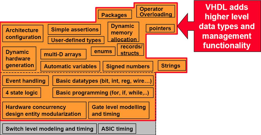
2 Verilog & SystemVerilog 1984 Verilog invented, C-like syntax First standard Verilog 95 Extra features Verilog 2001 A super set - SystemVerilog VHDL pdf 2

3 Verilog vs VHDL VHDL

4 SystemVerilog 4
5 SystemVerilog constructs Flip-flop Register Adder Multiplier (signed, unsigned) Concatenation Priority decoder Memory (sync and async)
6 Synch and Single Pulse reg x,y; // variable type (0,1,Z,X) wire button; // net type (0,1,Z,X) // SSP clk) begin x <= stb; y <= x; assign button = x & ~y; // procedural block //continuous assignment stb x y button & 6
7 Is this the same thing? reg x,y; // variable type (0,1,Z,X) wire button; // net type (0,1,Z,X) // SSP clk) begin x <= stb; clk) begin y <= x; assign button = x & ~y; // procedural block // procedural block stb x y button & 7
8 One more thing // This is OK clk) begin x <= stb; if (rst) x <= 0; // same as clk) begin if (rst) x <= 0; else x <= stb; // This is not OK (synth) // multiple assignment clk) begin x <= stb; clk) begin if (rst) x <= 0; 8
 c = a; // compilation warning always_comb if (b) c = a; // yes always_comb if (b) c = a; else c = d;")
9 SV: always_{comb, ff, latch} a 1 0 b c // forgot else branch // a synthesis warning or b) if (b) c = a; // compilation warning always_comb if (b) c = a; // yes always_comb if (b) c = a; else c = d; 9
10 reg or wire in Verilog 1) 2) always a <= b & c; reg both wire both assign a = b & c; both wire 3) wire both module 10
11 SV relaxes variable use A variable can receive a value from one of these : any number of always/initial-blocks one always_ff/always_comb-block one continuous assignment one module instance We can skip wire If you don t like reg, use logic instead 11
12 Signed/unsigned Numbers in verilog (95) are unsigned. If you write assign d3 = s + d2; s and d2 get zero-exted wire signed [4:0] d3; reg signed [3:0] s; wire signed [3:0] d2; assign d3 = s + d2; s and d2 get sign-exted 12
13 Blocking vs Non-Blocking Blocking assignment (=) Assignments are blocked when executing The statements will be executed in sequence, one after one clk) begin B = A; C = B; Non-blocking assignment (<=) Assignments are not blocked The statements will be executed concurrently clk) begin B <= A; C <= B; Use <= for sequential logic 13
14 Blocking vs Non-Blocking always_comb begin C = A & B; E = C D; always_comb begin C <= A & B; E <= C D; Same result Use = for combinatorial logic 14
15 Verilog constructs for synthesis Construct type Keyword Notes ports input, inout, output parameters module definition parameter module signals and variables wire, reg Vectors are allowed instantiation module instances E.g., mymux ml(out, io, il, s); Functions and tasks function, task Timing constructs ignored procedural always, if, then, else, case initial is not supported data flow assign Delay information is ignored loops for, while, forever procedural blocks begin,, named blocks, disable Disabling of named blocks allowed 15

16 Operators Replication {3{a}} same as {a,a,a} 16
17 Parameters module w(x,y); input x; output y; parameter z=16; localparam s=3 h1;... w w0(a,b); w #(8) w1(a,b); w #(.z(32)) w2(.x(a),.y(b)); module 17
18 Constants... `include myconstants.v `define PKMC `define S0 1 b0 `define S1 1 b1 `ifdef PKMC... `else... `if 18
19 Comment: FSM1 x NEXT s OUT u 1(1) 0 1 0(1) 0(0) 1(0) //NEXT clk) begin if (rst) s <= `S0; else case (s) `S0: if (x) s <= `S1; default: if (x) s <= `S0; //OUT always_comb begin case (s) `S0: if (x) u = 1 b1; else u = 1 b0; default: if (x) u = 1 b0; else u = 1 b1; 19
20 Comment: FSM2 x COMB ns s u 1(1) 0(1) 0 1 // COMB always_comb begin ns = `S0; // defaults u = 1 b0; case (s) `S0: if (x) begin ns = `S1; u = 1 b1; default: if (~x) begin u = 1 b1; ns = `S1; 0(0) 1(0) // state register clk) begin if (rst) s <= `S0; else s <= ns; 20
21 Good to have typedef logic [3:0] nibble; nibble nibblea, nibbleb; typedef enum {WAIT, LOAD, STORE} state_t; state_t state, next_state; typedef struct { logic [4:0] alu_ctrl; logic stb,ack; state_t state } control_t; control_t control; assign control.ack = 1 b0; 21
22 System tasks Initialize memory from file module test; reg [31:0] mem[0:511]; // 512x32 memory integer i; initial begin $readmemh( init.dat, mem); for (i=0; i<512; i=i+1) $display( mem %0d: %h, i, mem[i]); // with CR... module 22
23 initial begin uart1.putstr( s 0 ); Do you want a nicer test bench? => Try a task or two! my_test_bench cl k compute r rs t uart t x r x uart_task s getch putch cl k putstr computer 1 uart1 23
24 Tasks module uart_tasks(input clk, uart_tx, output logic uart_rx); initial begin uart_rx = 1'b1; task getch(); reg [7:0] char; uart_tx); #4340; #8680; for (int i=0; i<8; i++) begin char[i] = uart_tx; #8680; $fwrite(32'h1,"%c", char); task // getch task putch(input byte char); begin uart_rx = 1'b0; for (int i=0; i<8; i++) #8680 uart_rx = char[i]; #8680 uart_rx = 1'b1; #8680; task // putch task putstr(input string str); byte ch; begin for (int i=0; i<str.len; i++) begin ch = str[i]; if (ch) putch(ch); putch(8'h0d); task // putstr module // uart_tb 24
25 In the testbench wire tx,rx;... // s a command initial begin # // wait 100 us uart1.putstr( s 0 ); // instantiate the test UART uart_tasks uart1(.*); // instantiate the computer computer computer1(.*); 25

26 Lab 0 : Build a UART in Verilog USB clk = 40 MHz baud rate = us full duplex Start stop 26
27 UCF = User constraint file CONFIG PART = XC2V4000-FF ; NET "clk" LOC = "AK19"; # SWx buttons NET "stb" LOC = "B3" ; NET "rst" LOC = "C2" ; # LEDs NET "u<0>" LOC = "N9"; //leftmost NET "u<1>" LOC = "P8"; NET "u<2>" LOC = "N8"; NET "u<3>" LOC = "N7"; # DIP switches NET "kb<0>" LOC = "AL3"; //leftmost NET "kb<1>" LOC = "AK3"; NET "kb<2>" LOC = "AJ5"; NET "kb<3>" LOC = "AH6"; 27
28 Lab0: Testbench s rst DIP switch 0x41 kb tx LEDs 0x41 u rx clk 28
29 Arrays-packed/unpacked wire [31:0] bus; reg [3:0][7:0] mem; // a packed array // so is this // both are contiguous assign bus = mem; assign bus[31:16] = mem[3:2]; mem[3][7:0] mem[2][7:0] mem[1][7:0] mem[0][7:0] 31 bus[31:0] 0 29
30 Arrays-packed/unpacked wire [31:0] bus; reg [7:0] mem [0:3]; // 4 bytes assign bus[31:24] = mem[3]; 7 0 mem[0][7:0] mem[1][7:0] mem[2][7:0] mem[3][7:0] 31 bus[31:0] 0 30
31 Case study Two square wave generators driven by an FSM reading from an 8 bit wide ROM The 8 bit wide ROM is divided into 8 word packets Addr 0: LSB of number of clock cycles for this packet Addr 1: MSB of number of clock cycles for this packet Addr 2,3: LSB, MSB of square wave period, channel 1 Addr 4,5: LSB, MSB of square wave period, channel 2 Addr 6,7: Unused
A short introduction to SystemVerilog. For those who know VHDL We aim for synthesis
 A short introduction to SystemVerilog For those who know VHDL We aim for synthesis 1 Verilog & SystemVerilog 1984 Verilog invented, C-like syntax First standard Verilog 95 Extra features Verilog 2001 A
TSEA44: Computer hardware a system on a chip
 TSEA44: Computer hardware a system on a chip Lecture 2: A short introduction to SystemVerilog (System)Verilog 2016-11-02 2 Assume background knowledge of VHDL and logic design Focus on coding for synthesis
Digital Design with SystemVerilog
 Digital Design with SystemVerilog Prof. Stephen A. Edwards Columbia University Spring 25 Synchronous Digital Design Combinational Logic Sequential Logic Summary of Modeling Styles Testbenches Why HDLs?
Quick Introduction to SystemVerilog: Sequental Logic
 ! Quick Introduction to SystemVerilog: Sequental Logic Lecture L3 8-545 Advanced Digital Design ECE Department Many elements Don Thomas, 24, used with permission with credit to G. Larson Today Quick synopsis
A Brief Introduction to Verilog Hardware Definition Language (HDL)
") www.realdigital.org A Brief Introduction to Verilog Hardware Definition Language (HDL) Forward Verilog is a Hardware Description language (HDL) that is used to define the structure and/or behavior of digital
www.realdigital.org A Brief Introduction to Verilog Hardware Definition Language (HDL) Forward Verilog is a Hardware Description language (HDL) that is used to define the structure and/or behavior of digital
SystemVerilog 3.1: It s What The DAVEs In Your Company Asked For
 February 24-26, 2003 SystemVerilog 3.1: It s What The DAVEs In Your Company Asked For Stuart HDL, Inc. www.sutherland-hdl.com 2/27/2003 1 This presentation will Define what is SystemVerilog Provide an
Last Lecture. Talked about combinational logic always statements. e.g., module ex2(input logic a, b, c, output logic f); logic t; // internal signal
; logic t; // internal signal") Last Lecture Talked about combinational logic always statements. e.g., module ex2(input logic a, b, c, output logic f); logic t; // internal signal always_comb t = a & b; f = t c; should use = (called
Last Lecture Talked about combinational logic always statements. e.g., module ex2(input logic a, b, c, output logic f); logic t; // internal signal always_comb t = a & b; f = t c; should use = (called
Testbenches for Sequential Circuits... also, Components
 ! Testbenches for Sequential Circuits... also, Components Lecture L04 18-545 Advanced Digital Design ECE Department Many elements Don Thomas, 2014, used with permission with credit to G. Larson State Transition
Chapter 4 :: Topics. Introduction. SystemVerilog. Hardware description language (HDL): allows designer to specify logic function only.
: allows designer to specify logic function only.") Chapter 4 :: Hardware Description Languages Digital Design and Computer Architecture David Money Harris and Sarah L. Harris Chapter 4 :: Topics Introduction Combinational Logic Structural Modeling Sequential
Chapter 4 :: Hardware Description Languages Digital Design and Computer Architecture David Money Harris and Sarah L. Harris Chapter 4 :: Topics Introduction Combinational Logic Structural Modeling Sequential
EECS150 - Digital Design Lecture 10 Logic Synthesis
 EECS150 - Digital Design Lecture 10 Logic Synthesis February 13, 2003 John Wawrzynek Spring 2003 EECS150 Lec8-synthesis Page 1 Logic Synthesis Verilog and VHDL started out as simulation languages, but
EECS150 - Digital Design Lecture 10 Logic Synthesis
 EECS150 - Digital Design Lecture 10 Logic Synthesis September 26, 2002 John Wawrzynek Fall 2002 EECS150 Lec10-synthesis Page 1 Logic Synthesis Verilog and VHDL stated out as simulation languages, but quickly
CAD for VLSI Design - I. Lecture 21 V. Kamakoti and Shankar Balachandran
 CAD for VLSI Design - I Lecture 21 V. Kamakoti and Shankar Balachandran Overview of this Lecture Understanding the process of Logic synthesis Logic Synthesis of HDL constructs Logic Synthesis What is this?
Chapter 4. Digital Design and Computer Architecture, 2 nd Edition. David Money Harris and Sarah L. Harris. Chapter 4 <1>
 Chapter 4 Digital Design and Computer Architecture, 2 nd Edition David Money Harris and Sarah L. Harris Chapter 4 Chapter 4 :: Topics Introduction Combinational Logic Structural Modeling Sequential
CSE140L: Components and Design Techniques for Digital Systems Lab
 CSE140L: Components and Design Techniques for Digital Systems Lab Tajana Simunic Rosing Source: Vahid, Katz, Culler 1 Announcements & Outline Lab 4 due; demo signup times listed on the cse140l site Check
Synthesis vs. Compilation Descriptions mapped to hardware Verilog design patterns for best synthesis. Spring 2007 Lec #8 -- HW Synthesis 1
 Verilog Synthesis Synthesis vs. Compilation Descriptions mapped to hardware Verilog design patterns for best synthesis Spring 2007 Lec #8 -- HW Synthesis 1 Logic Synthesis Verilog and VHDL started out
Lecture 32: SystemVerilog
 Lecture 32: SystemVerilog Outline SystemVerilog module adder(input logic [31:0] a, input logic [31:0] b, output logic [31:0] y); assign y = a + b; Note that the inputs and outputs are 32-bit busses. 17:
CSE140L: Components and Design
 CSE140L: Components and Design Techniques for Digital Systems Lab Tajana Simunic Rosing Source: Vahid, Katz, Culler 1 Grade distribution: 70% Labs 35% Lab 4 30% Lab 3 20% Lab 2 15% Lab 1 30% Final exam
Verilog: The Next Generation Accellera s SystemVerilog Standard
 Verilog: The Next Generation Accellera s SystemVerilog Standard by Stuart Verilog HD and PI Expert HD, Inc. Training engineers to be HD wizards 1 Overview! Define what is SystemVerilog! Justify the need
Logic Synthesis. EECS150 - Digital Design Lecture 6 - Synthesis
 Logic Synthesis Verilog and VHDL started out as simulation languages, but quickly people wrote programs to automatically convert Verilog code into low-level circuit descriptions (netlists). EECS150 - Digital
Verilog introduction. Embedded and Ambient Systems Lab
 Verilog introduction Embedded and Ambient Systems Lab Purpose of HDL languages Modeling hardware behavior Large part of these languages can only be used for simulation, not for hardware generation (synthesis)
ECE 574: Modeling and Synthesis of Digital Systems using Verilog and VHDL. Fall 2017 Final Exam (6.00 to 8.30pm) Verilog SOLUTIONS
 Verilog SOLUTIONS") ECE 574: Modeling and Synthesis of Digital Systems using Verilog and VHDL Fall 2017 Final Exam (6.00 to 8.30pm) Verilog SOLUTIONS Note: Closed book no notes or other material allowed apart from the one
ECE 574: Modeling and Synthesis of Digital Systems using Verilog and VHDL Fall 2017 Final Exam (6.00 to 8.30pm) Verilog SOLUTIONS Note: Closed book no notes or other material allowed apart from the one
EECS150 - Digital Design Lecture 5 - Verilog Logic Synthesis
 EECS150 - Digital Design Lecture 5 - Verilog Logic Synthesis Jan 31, 2012 John Wawrzynek Spring 2012 EECS150 - Lec05-verilog_synth Page 1 Outline Quick review of essentials of state elements Finite State
Synthesis of Language Constructs. 5/10/04 & 5/13/04 Hardware Description Languages and Synthesis
 Synthesis of Language Constructs 1 Nets Nets declared to be input or output ports are retained Internal nets may be eliminated due to logic optimization User may force a net to exist trireg, tri0, tri1
EECS 470 Lab 1. Verilog: Hardware Description Language
 EECS 470 Lab 1 Verilog: Hardware Description Language Department of Electrical Engineering and Computer Science College of Engineering University of Michigan Thursday, 6 th September, 2018 (University
FPGA Design Challenge :Techkriti 14 Digital Design using Verilog Part 1
 FPGA Design Challenge :Techkriti 14 Digital Design using Verilog Part 1 Anurag Dwivedi Digital Design : Bottom Up Approach Basic Block - Gates Digital Design : Bottom Up Approach Gates -> Flip Flops Digital
Last Lecture: Divide by 3 FSM
 Last Lecture: Divide by 3 FSM Output should be 1 every 3 clock cycles S2 S0 S1 The double circle indicates the reset state Slide derived from slides by Harris & Harris from their book 1 Finite State Machines
CSE 502: Computer Architecture
 CSE 502: Computer Architecture SystemVerilog More Resources Cannot cover everything in one day You will likely need to look up reference material: SystemVerilog for VHDL Users: http://www.systemverilog.org/techpapers/date04_systemverilog.pdf
CMPE 415 Parameterized Modules and Simulation
 Department of Computer Science and Electrical Engineering CMPE 415 Parameterized Modules and Simulation Prof. Ryan Robucci Parameters Modules may include parameters that can be overridden for tuning behavior
Date Performed: Marks Obtained: /10. Group Members (ID):. Experiment # 11. Introduction to Verilog II Sequential Circuits
:. Experiment # 11. Introduction to Verilog II Sequential Circuits") Name: Instructor: Engr. Date Performed: Marks Obtained: /10 Group Members (ID):. Checked By: Date: Experiment # 11 Introduction to Verilog II Sequential Circuits OBJECTIVES: To understand the concepts
Name: Instructor: Engr. Date Performed: Marks Obtained: /10 Group Members (ID):. Checked By: Date: Experiment # 11 Introduction to Verilog II Sequential Circuits OBJECTIVES: To understand the concepts
Synthesizable Verilog
 Synthesizable Verilog Courtesy of Dr. Edwards@Columbia, and Dr. Franzon@NCSU http://csce.uark.edu +1 (479) 575-6043 yrpeng@uark.edu Design Methodology Structure and Function (Behavior) of a Design HDL
!== vs.!= and === vs. ==
 !== vs.!= and === vs. == In SystemVerilog, logic is a 4-state signal type with values 0, 1, X, Z. If a signal is never assigned to, ModelSim will assume that has an xxx xxx value. This means if you do
EEL 4783: HDL in Digital System Design
 EEL 4783: HDL in Digital System Design Lecture 15: Logic Synthesis with Verilog Prof. Mingjie Lin 1 Verilog Synthesis Synthesis vs. Compilation Descriptions mapped to hardware Verilog design patterns for
HDLs and SystemVerilog. Digital Computer Design
 HDLs and SystemVerilog Digital Computer Design Logic Arrays Gates can be organized into regular arrays. If the connections are made programmable, these logic arrays can be configured to perform any function
Online Verilog Resources
 EECS 427 Discussion 6: Verilog HDL Reading: Many references EECS 427 F08 Discussion 6 1 Online Verilog Resources ASICs the book, Ch. 11: http://www.ge.infn.it/~pratolo/verilog/verilogtutorial.pdf it/ pratolo/verilog/verilogtutorial
EECS 470 Lab 1. Verilog: Hardware Description Language
 EECS 470 Lab 1 Verilog: Hardware Description Language Department of Electrical Engineering and Computer Science College of Engineering University of Michigan Thursday, 10 th January, 2019 (University of
VERILOG 2: LANGUAGE BASICS
 VERILOG 2: LANGUAGE BASICS Verilog module Modules are basic building blocks. These are two example module definitions which you should use: // Safer traditional method module abc (in1, in2, out); input
Introduction to Verilog/System Verilog
 NTUEE DCLAB Feb. 27, 2018 Introduction to Verilog/System Verilog Presenter: Yao-Pin Wang 王耀斌 Advisor: Prof. Chia-Hsiang Yang 楊家驤 Dept. of Electrical Engineering, NTU National Taiwan University What is
Spiral 1 / Unit 4 Verilog HDL. Digital Circuit Design Steps. Digital Circuit Design OVERVIEW. Mark Redekopp. Description. Verification.
 1-4.1 1-4.2 Spiral 1 / Unit 4 Verilog HDL Mark Redekopp OVERVIEW 1-4.3 1-4.4 Digital Circuit Design Steps Digital Circuit Design Description Design and computer-entry of circuit Verification Input Stimulus
What, If Anything, In SystemVerilog Will Help Me With FPGA-based Design. Stuart Sutherland, Consultant and Trainer, Sutherland HDL, Inc.
 What, If Anything, In SystemVerilog Will Help Me With FPGA-based Design Stuart Sutherland, Consultant and Trainer, Sutherland HDL, Inc. About the Presenter... Stuart Sutherland, SystemVerilog wizard Independent
Computer Aided Design Basic Syntax Gate Level Modeling Behavioral Modeling. Verilog
 Verilog Radek Pelánek and Šimon Řeřucha Contents 1 Computer Aided Design 2 Basic Syntax 3 Gate Level Modeling 4 Behavioral Modeling Computer Aided Design Hardware Description Languages (HDL) Verilog C
Graduate Institute of Electronics Engineering, NTU Design of Datapath Controllers
 Design of Datapath Controllers Lecturer: Wein-Tsung Shen Date: 2005.04.01 ACCESS IC LAB Outline Sequential Circuit Model Finite State Machines Useful Modeling Techniques pp. 2 Model of Sequential Circuits
Behavioral Modeling and Timing Constraints
 Lab Workbook Introduction Behavioral modeling was introduced in Lab 1 as one of three widely used modeling styles. Additional capabilities with respect to testbenches were further introduced in Lab 4.
Hardware Description Language (HDL)
") Hardware Description Language (HDL) What is the need for Hardware Description Language? Model, Represent, And Simulate Digital Hardware Hardware Concurrency Parallel Activity Flow Semantics for Signal
Hardware Description Language (HDL) What is the need for Hardware Description Language? Model, Represent, And Simulate Digital Hardware Hardware Concurrency Parallel Activity Flow Semantics for Signal
Lab 7 (All Sections) Prelab: Introduction to Verilog
 Prelab: Introduction to Verilog") Lab 7 (All Sections) Prelab: Introduction to Verilog Name: Sign the following statement: On my honor, as an Aggie, I have neither given nor received unauthorized aid on this academic work 1 Objective The
Lab 7 (All Sections) Prelab: Introduction to Verilog Name: Sign the following statement: On my honor, as an Aggie, I have neither given nor received unauthorized aid on this academic work 1 Objective The
Digital Design (VIMIAA01) Introduction to the Verilog HDL
 Introduction to the Verilog HDL") BUDAPEST UNIVERSITY OF TECHNOLOGY AND ECONOMICS FACULTY OF ELECTRICAL ENGINEERING AND INFORMATICS DEPARTMENT OF MEASUREMENT AND INFORMATION SYSTEMS Digital Design (VIMIAA01) Introduction to the Verilog
BUDAPEST UNIVERSITY OF TECHNOLOGY AND ECONOMICS FACULTY OF ELECTRICAL ENGINEERING AND INFORMATICS DEPARTMENT OF MEASUREMENT AND INFORMATION SYSTEMS Digital Design (VIMIAA01) Introduction to the Verilog
IP Core Design. Lecture 6 Introduction to Verilog-2001
 IP Core Design Lecture 6 Introduction to Juinn-Dar Huang, Ph.D. Assistant Professor jdhuang@mail.nctu.edu.tw September 2004 1 The official standard is IEEE Std. 1364-2001 a guide to the new features of
Digital Design with SystemVerilog
 Digital Design with SystemVerilog Prof. Stephen A. Edwards Columbia University Spring 24 Synchronous Digital Design Combinational Logic Sequential Logic Summary of Modeling Styles Example: Bresenham s
EN164: Design of Computing Systems Lecture 06: Lab Foundations / Verilog 2
 EN164: Design of Computing Systems Lecture 06: Lab Foundations / Verilog 2 Professor Sherief Reda http://scaleenginbrownedu Electrical Sciences and Computer Engineering School of Engineering Brown University
M A S S A C H U S E T T S I N S T I T U T E O F T E C H N O L O G Y DEPARTMENT OF ELECTRICAL ENGINEERING AND COMPUTER SCIENCE
 M A S S A C H U S E T T S I N S T I T U T E O F T E C H N O L O G Y DEPARTMENT OF ELECTRICAL ENGINEERING AND COMPUTER SCIENCE 6.111 Introductory Digital Systems Laboratory Fall 2017 Lecture PSet #6 of
Synthesis of Combinational and Sequential Circuits with Verilog
 Synthesis of Combinational and Sequential Circuits with Verilog What is Verilog? Hardware description language: Are used to describe digital system in text form Used for modeling, simulation, design Two
Digital Integrated Circuits
 Digital Integrated Circuits Lecture 5 Jaeyong Chung System-on-Chips (SoC) Laboratory Incheon National University MULTIPLE initial/always In C (single-threaded), a single statement is being executed at
ECEN : Microprocessor System Design Department of Electrical and Computer Engineering Texas A&M University. Homework #1 Solutions
 ECEN 449 749: Microprocessor System Design Department of Electrical and Computer Engineering Texas A&M University Homework #1 Solutions Upload your homework solution to ecampus as a single pdf file. Your
Department of Computer Science and Electrical Engineering. Intro to Verilog II
 Department of Computer Science and Electrical Engineering Intro to Verilog II http://6004.csail.mit.edu/6.371/handouts/l0{2,3,4}.pdf http://www.asic-world.com/verilog/ http://www.verilogtutorial.info/
Lab 7 (Sections 300, 301 and 302) Prelab: Introduction to Verilog
 Prelab: Introduction to Verilog") Lab 7 (Sections 300, 301 and 302) Prelab: Introduction to Verilog Name: Sign the following statement: On my honor, as an Aggie, I have neither given nor received unauthorized aid on this academic work
Lab 7 (Sections 300, 301 and 302) Prelab: Introduction to Verilog Name: Sign the following statement: On my honor, as an Aggie, I have neither given nor received unauthorized aid on this academic work
271/469 Verilog Tutorial
 271/469 Verilog Tutorial Prof. Scott Hauck, last revised 8/14/17 Introduction The following tutorial is inted to get you going quickly in circuit design in Verilog. It isn t a comprehensive guide to System
MCMASTER UNIVERSITY EMBEDDED SYSTEMS
 MCMASTER UNIVERSITY EMBEDDED SYSTEMS Computer Engineering 4DS4 Lecture Revision of Digital Systems Amin Vali January 26 Course material belongs to DrNNicolici Field programmable gate arrays (FPGAs) x x
EECS 470 Lab 3. SystemVerilog Style Guide. Department of Electrical Engineering and Computer Science College of Engineering University of Michigan
 EECS 470 Lab 3 SystemVerilog Style Guide Department of Electrical Engineering and Computer Science College of Engineering University of Michigan Thursday, 18 th January 2018 (University of Michigan) Lab
VHDL: RTL Synthesis Basics. 1 of 59
 VHDL: RTL Synthesis Basics 1 of 59 Goals To learn the basics of RTL synthesis. To be able to synthesize a digital system, given its VHDL model. To be able to relate VHDL code to its synthesized output.
Logic Circuits II ECE 2411 Thursday 4:45pm-7:20pm. Lecture 3
 Logic Circuits II ECE 2411 Thursday 4:45pm-7:20pm Lecture 3 Lecture 3 Topics Covered: Chapter 4 Discuss Sequential logic Verilog Coding Introduce Sequential coding Further review of Combinational Verilog
Modeling Sequential Circuits in Verilog
 Modeling Sequential Circuits in Verilog COE 202 Digital Logic Design Dr. Muhamed Mudawar King Fahd University of Petroleum and Minerals Presentation Outline Modeling Latches and Flip-Flops Blocking versus
EN2911X: Reconfigurable Computing Topic 02: Hardware Definition Languages
 EN2911X: Reconfigurable Computing Topic 02: Hardware Definition Languages Professor Sherief Reda http://scale.engin.brown.edu School of Engineering Brown University Spring 2014 1 Introduction to Verilog
ENGN1640: Design of Computing Systems Topic 02: Design/Lab Foundations
 ENGN1640: Design of Computing Systems Topic 02: Design/Lab Foundations Professor Sherief Reda http://scale.engin.brown.edu School of Engineering Brown University Spring 2017 1 Topics 1. Programmable logic
Course Topics - Outline
 Course Topics - Outline Lecture 1 - Introduction Lecture 2 - Lexical conventions Lecture 3 - Data types Lecture 4 - Operators Lecture 5 - Behavioral modeling A Lecture 6 Behavioral modeling B Lecture 7
Chapter 2 Using Hardware Description Language Verilog. Overview
 Chapter 2 Using Hardware Description Language Verilog CSE4210 Winter 2012 Mokhtar Aboelaze based on slides by Dr. Shoab A. Khan Overview Algorithm development isa usually done in MATLAB, C, or C++ Code
The Verilog Language COMS W Prof. Stephen A. Edwards Fall 2002 Columbia University Department of Computer Science
 The Verilog Language COMS W4995-02 Prof. Stephen A. Edwards Fall 2002 Columbia University Department of Computer Science The Verilog Language Originally a modeling language for a very efficient event-driven
Verilog Execution Semantics
 System Verilog (SV) is a parallel, hardware description language. SV differs from procedural languages such as C in that it models concurrency in digital logic. Logic gates operate in parallel, but software
Example Best and Median Results
 Example Best and Median Results Targeting Delay Only: effectively create 16 SHA256 units to work in parallel Targeting Area*Delay: effectively use one SHA256 unit to enumerate 16 nonces Best Delay Only
Verilog for Synthesis Ing. Pullini Antonio
 Verilog for Synthesis Ing. Pullini Antonio antonio.pullini@epfl.ch Outline Introduction to Verilog HDL Describing combinational logic Inference of basic combinational blocks Describing sequential circuits
ENGN1640: Design of Computing Systems Topic 02: Design/Lab Foundations
 ENGN1640: Design of Computing Systems Topic 02: Design/Lab Foundations Professor Sherief Reda http://scale.engin.brown.edu School of Engineering Brown University Spring 2016 1 Topics 1. Programmable logic
Building Bigger Systems: Interfacing
 ! Building Bigger Systems: Interfacing Lecture L07 18-545 Advanced Digital Design ECE Department Many elements Don Thomas, 2014, used with permission with credit to G. Larson Basic Principles Reading:
Note: Closed book no notes or other material allowed, no calculators or other electronic devices.
 ECE 574: Modeling and Synthesis of Digital Systems using Verilog and VHDL Fall 2017 Exam Review Note: Closed book no notes or other material allowed, no calculators or other electronic devices. One page
SystemVerilog Design: User Experience Defines Multi-Tool, Multi-Vendor Language Working Set Experience from Four Years of SVD Adoption
 SystemVerilog Design: User Experience Defines Multi-Tool, Multi-Vendor Language Working Set Experience from Four Years of SVD Adoption Junette Tan, PMC Agenda Motivating Factors for SV Adoption Migration
PINE TRAINING ACADEMY
 PINE TRAINING ACADEMY Course Module A d d r e s s D - 5 5 7, G o v i n d p u r a m, G h a z i a b a d, U. P., 2 0 1 0 1 3, I n d i a Digital Logic System Design using Gates/Verilog or VHDL and Implementation
Schematic design. Gate level design. 0 EDA (Electronic Design Assistance) 0 Classical design. 0 Computer based language
 0 Classical design. 0 Computer based language") 1 / 15 2014/11/20 0 EDA (Electronic Design Assistance) 0 Computer based language 0 HDL (Hardware Description Language) 0 Verilog HDL 0 Created by Gateway Design Automation Corp. in 1983 First modern hardware
1 / 15 2014/11/20 0 EDA (Electronic Design Assistance) 0 Computer based language 0 HDL (Hardware Description Language) 0 Verilog HDL 0 Created by Gateway Design Automation Corp. in 1983 First modern hardware
Recommended Design Techniques for ECE241 Project Franjo Plavec Department of Electrical and Computer Engineering University of Toronto
 Recommed Design Techniques for ECE241 Project Franjo Plavec Department of Electrical and Computer Engineering University of Toronto DISCLAIMER: The information contained in this document does NOT contain
Verilog. What is Verilog? VHDL vs. Verilog. Hardware description language: Two major languages. Many EDA tools support HDL-based design
 Verilog What is Verilog? Hardware description language: Are used to describe digital system in text form Used for modeling, simulation, design Two major languages Verilog (IEEE 1364), latest version is
Digital Design with FPGAs. By Neeraj Kulkarni
 Digital Design with FPGAs By Neeraj Kulkarni Some Basic Electronics Basic Elements: Gates: And, Or, Nor, Nand, Xor.. Memory elements: Flip Flops, Registers.. Techniques to design a circuit using basic
VHDL. VHDL History. Why VHDL? Introduction to Structured VLSI Design. Very High Speed Integrated Circuit (VHSIC) Hardware Description Language
 Hardware Description Language") VHDL Introduction to Structured VLSI Design VHDL I Very High Speed Integrated Circuit (VHSIC) Hardware Description Language Joachim Rodrigues A Technology Independent, Standard Hardware description Language
VHDL Introduction to Structured VLSI Design VHDL I Very High Speed Integrated Circuit (VHSIC) Hardware Description Language Joachim Rodrigues A Technology Independent, Standard Hardware description Language
Veriolog Overview. CS/EE 3710 Fall 2010
 Veriolog Overview CS/EE 3710 Fall 2010 Hardware Description Languages HDL Designed to be an alternative to schematics for describing hardware systems Two main survivors VHDL Commissioned by DOD Based on
EECS 470 Lab 6. SystemVerilog. Department of Electrical Engineering and Computer Science College of Engineering. (University of Michigan)
") EECS 470 Lab 6 SystemVerilog Department of Electrical Engineering and Computer Science College of Engineering University of Michigan Thursday, October. 18 th, 2018 Thursday, October. 18 th, 2018 1 / Overview
EECS 470 Lab 6 SystemVerilog Department of Electrical Engineering and Computer Science College of Engineering University of Michigan Thursday, October. 18 th, 2018 Thursday, October. 18 th, 2018 1 / Overview
Course Topics - Outline
 Course Topics - Outline Lecture 1 - Introduction Lecture 2 - Lexical conventions Lecture 3 - Data types Lecture 4 - Operators Lecture 5 - Behavioral modeling A Lecture 6 Behavioral modeling B Lecture 7
DIGITAL SYSTEM DESIGN
 DIGITAL SYSTEM DESIGN Prepared By: Engr. Yousaf Hameed Lab Engineer BASIC ELECTRICAL & DIGITAL SYSTEMS LAB DEPARTMENT OF ELECTRICAL ENGINEERING Digital System Design 1 Name: Registration No: Roll No: Semester:
Digital Circuit Design and Language. Datapath Design. Chang, Ik Joon Kyunghee University
 Digital Circuit Design and Language Datapath Design Chang, Ik Joon Kyunghee University Typical Synchronous Design + Control Section : Finite State Machine + Data Section: Adder, Multiplier, Shift Register
CSE 591: Advanced Hardware Design and Verification (2012 Spring) LAB #0
 LAB #0") Lab 0: Tutorial on Xilinx Project Navigator & ALDEC s Active-HDL Simulator CSE 591: Advanced Hardware Design and Verification Assigned: 01/05/2011 Due: 01/19/2011 Table of Contents 1 Overview... 2 1.1
Lab 0: Tutorial on Xilinx Project Navigator & ALDEC s Active-HDL Simulator CSE 591: Advanced Hardware Design and Verification Assigned: 01/05/2011 Due: 01/19/2011 Table of Contents 1 Overview... 2 1.1
Verilog for Modeling - Module 9
 Verilog for Modeling Module 9 Jim Duckworth, WPI 1 General examples AND model Flip-flop model SRAM Model Customizing Models Generics in VHDL DDR SDRAM Model Parameters in Verilog Overview Commercial memory
Intro to HW Design & Externs for P4àNetFPGA. CS344 Lecture 5
 Intro to HW Design & Externs for P4àNetFPGA CS344 Lecture 5 Announcements Updated deliverable description for next Tuesday Implement most of the required functionality Make sure baseline tests are passing
Verilog for High Performance
 Verilog for High Performance Course Description This course provides all necessary theoretical and practical know-how to write synthesizable HDL code through Verilog standard language. The course goes
EECS 427 Lecture 14: Verilog HDL Reading: Many handouts/references. EECS 427 W07 Lecture 14 1
 EECS 427 Lecture 14: Verilog HDL Reading: Many handouts/references EECS 427 W07 Lecture 14 1 Online Verilog Resources ASICs the book, Ch. 11: http://www.ge.infn.it/~pratolo/verilog/verilogtutorial.pdf
In our case Dr. Johnson is setting the best practices
 VHDL Best Practices Best Practices??? Best practices are often defined by company, toolset or device In our case Dr. Johnson is setting the best practices These rules are for Class/Lab purposes. Industry
N-input EX-NOR gate. N-output inverter. N-input NOR gate
 Hardware Description Language HDL Introduction HDL is a hardware description language used to design and document electronic systems. HDL allows designers to design at various levels of abstraction. It
CS6710 Tool Suite. Verilog is the Key Tool
 CS6710 Tool Suite Verilog-XL Behavioral Verilog Your Library Cadence SOC Encounter Synopsys Synthesis Structural Verilog Circuit Layout CSI Verilog-XL AutoRouter Cadence Virtuoso Layout LVS Layout-XL Cadence
In this lecture, we will go beyond the basic Verilog syntax and examine how flipflops and other clocked circuits are specified.
 1 In this lecture, we will go beyond the basic Verilog syntax and examine how flipflops and other clocked circuits are specified. I will also introduce the idea of a testbench as part of a design specification.
A Verilog Primer. An Overview of Verilog for Digital Design and Simulation
 A Verilog Primer An Overview of Verilog for Digital Design and Simulation John Wright Vighnesh Iyer Department of Electrical Engineering and Computer Sciences College of Engineering, University of California,
Two HDLs used today VHDL. Why VHDL? Introduction to Structured VLSI Design
 Two HDLs used today Introduction to Structured VLSI Design VHDL I VHDL and Verilog Syntax and ``appearance'' of the two languages are very different Capabilities and scopes are quite similar Both are industrial
(System)Verilog Tutorial Aleksandar Milenković
Verilog Tutorial Aleksandar Milenković") (System)Verilog Tutorial Aleksandar Milenković The LaCASA Laboratory Electrical and Computer Engineering Department The University of Alabama in Huntsville Email: milenka@ece.uah.edu Web: http://www.ece.uah.edu/~milenka
(System)Verilog Tutorial Aleksandar Milenković The LaCASA Laboratory Electrical and Computer Engineering Department The University of Alabama in Huntsville Email: milenka@ece.uah.edu Web: http://www.ece.uah.edu/~milenka
Lab 1.5 (Warmup): Synthesis Workflow and SystemVerilog Register File Not Due
: Synthesis Workflow and SystemVerilog Register File Not Due") CMU 18-447: Introduction to Computer Architecture Lab 1.5 (Warmup): Synthesis Workflow and SystemVerilog Register File Not Due In this tutorial, you will take a quick tour of the tools we will use in this
CMU 18-447: Introduction to Computer Architecture Lab 1.5 (Warmup): Synthesis Workflow and SystemVerilog Register File Not Due In this tutorial, you will take a quick tour of the tools we will use in this
OVERVIEW: ============================================================ REPLACE
 OVERVIEW: With mantis 928, formal arguments to properties and sequences are defined to apply to a list of arguments that follow, much like tasks and function arguments. Previously, the type had to be replicated
Department of Computer Science and Electrical Engineering. CMPE 415 Verilog Events Timing and Testbenches Prof. Ryan Robucci
 Department of Computer Science and Electrical Engineering CMPE 415 Verilog Events Timing and Testbenches Prof. Ryan Robucci An Event Driven Language also used for Synthesis We emphasize use of Verilog
Yet Another Latch and Gotchas Paper
 and Gotchas Paper Don Mills Microchip Technology, INC Chandler, AZ, USA www.microchip.com ABSTRACT This paper discusses four SystemVerilog coding topics that can lead to inadvertent design bugs. Old constructs