C3 I20 I32 T11 ControlManager FB45
|
|
|
- Shon Wiggins
- 6 years ago
- Views:
Transcription


1 CONTROL TECHNOLOGY FROM PARKER C3 I20 I32 T11 ControlManager FB45 A1039 Version: 39
2 Warranty Disclaimer While efforts were made to verify the accuracy of the information contained in this documentation, Parker expressly disclaims all warranties with regard to this application note, including, but not limited to, the implied warranties of merchantability and fitness of a particular purpose. Parker does not warrant, guarantee, or make any representation regarding the use or the results of the use of this application note in terms of correctness, accuracy, or reliability. The contents of this application note are subject to change without notice. Parker will publish updates and revisions of this document as needed. The documents supersede all previous versions. Limitation of Liability You agree that Parker shall not be liable to you under this agreement for any damages, including without limitation any lost profits, or any consequential, incidental, or punitive damages arising out of the use or inability to use this application note and related documents, or for any claim by another party. You agree and hold Parker harmless for all claims and damages from any third party as a result of their use or inability to use any product that you develop based on this application note and the products and/or services documented herein. Parker Hannifin Manufacturing Germany GmbH & Co KG Business Development & Applications Copyright 2012 All Rights Reserved Europe Author: Klaus Zimmer Page 2/16
3 Table of Contents 1. DEVICE SUPPLEMENT With the option And the Master plc PURPOSE OF THE BLOCK Overview Restrictions and application History of modifications ADJUSTMENTS Compax3 configuration Compax3 Hardware SIMATIC - HW Config Application interface of "C3ControlManager" settings for external Master APPLICATION EXAMPLE Overview of the connection: cyclic channel (PZD) Acyclic channel (PKW) Application Positioning Parameter channel...13 Europe Author: Klaus Zimmer Page 3/16
4 1. Device supplement 1.1. With the option F10 F11 F12 I20 I32 T And the Master plc SIMATIC S7-300 SIMATIC S7-400 with integrated PROFIBUS DP Master (z. B. CPU315-2DP) or with integrated PROFINET IO Master (z. B. CPU315-2DP / CPU317-2PN) 1.3. The additional files C3T11_A1039 deu.pdf manual German C3T11_A1039 eng.pdf manual English C3I20T11_A1039.C3P example for C3S (C3M, C3H) (Profibus) PLCA1039B.zip example for SIMATIC S7 (Profibus) C3I32T11_A1039.C3P example for C3S (C3M, C3H) (ProfiNET) PLCA1039N.zip example for SIMATIC S7 (ProfiNET) 2. Purpose of the Block 2.1. Overview Absolute Symbol Comment Vers Date Device Application FB45 C3ControlManager C3 I20 T11 ControlManager :45:45 AM C3 I20 T11 Positioning, absolute / relative 2.2. Restrictions and application This block simplifies the control of a C3 T11 (with PROFIdrive profile) with the S7. The block needs the commands and set values. The block distributes messages and actual values form the drive. The channels PZD and PKW are used in both directions. This block is only usable with PPO13 others are strictly forbidden History of modifications 1. V :31:13 PM 2. V :37:48 PM - At change from positioning to manual (JOG) is no longer necessary to choose Stop first (STW1.4 = false and STW1.5 = false). - If <bstartpositioning> is not possible to be done, the block will save the reason. <bstartpositioning> (InOut Bit) is resettled in any case - Relative positioning is now possible without having done homing first. Europe Author: Klaus Zimmer Page 4/16
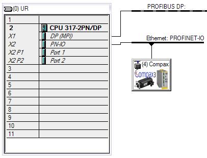
5 - Correction of Timer for Watchdog this was not stopped during a movement was not possible (e.g. not energized"). 3. V :24:21 PM Rising edge deception was corrected at positing - <bstartpositioning>: is only possible if the actual movement has react the target - <bchangesetimmediate>: can interrupt actual move (new target without stop) 3. V :45:45 AM - Delete <bposrunning> during disabling power stage. Otherwise it would necessary to wail until <bposerr> = True before a new order is accepted! 3. Adjustments 3.1. Compax3 configuration With C3ServoManager few following adjustments: At folder: \\ Communication \ PROFIBUS DP - node settings [PROFIBUS operation mode] Positioning [PLC -> Compax3] CW 1 Commanded positioning value (XCOMMANDED_A) Commanded motion speed D (32 Bit) Commanded acceleration B (32 Bit) [Compax3 -> PLC] SW 1 Actual position value XACTUAL_A Actual speed value NACTUAL_B (32 Bit) [Operation Mode Settings] Acyclic process data channel / Parameter channel Select with "PKW" Error response on field bus failure is up to user. \\ I20T11 drive configuration \ I/O - assignment Selection: - free - Fixed assignment It is recommended to select free. With Fixed assignment are used some Binary connections between control word and digital inputs (E0... E3), that cases if there is no plug at X12 the C3 is not possible to be controlled Compax3 Hardware DIP Switch: Bus address Bus plug: ``ON / OFF`` Bus termination resistance SIMATIC - HW Config Correlated to PPO-Type which is shown in the C3 configuration it is needed to select at SIMATIC - HW Config this type: Europe Author: Klaus Zimmer Page 5/16


6 Pic 1: SIMATIC - HW Config Pic 2: SIMATIC - HW Config Europe Author: Klaus Zimmer Page 6/16
7 Edit the Start address of PKW (here 256) in Instance Variable <nladdr> (DB45.DBW6) Application interface of C3ControlManager" Schematic drawing for in- and output Areas of FB45 / DB45 in input out output in_out In- and Output stat Static Memory EN DB45 ENO DBX0.0 benable benabled DBX2.0 DBX0.1 babsoluterelative bdriveerr DBX2.1 DBX0.2 bpositionresetmode bposrunning DBX2.2 DBX0.3 bhold binposition DBX2.3 DBX0.4 bstop bposerr DBX2.4 DBX0.5 bfaultreset bhomingrunning DBX2.5 DBX0.6 bjogp bhomingattained DBX2.6 DBX0.7 bjogn bhomingerr DBX2.7 DBX1.0 bexdatatransfer bcommerr DBX3.0 DBX4.0 bstartpositioning DBX4.1 bchangesetimmediate strd.ipositionvalue DBD46 DBX4.2 bstarthoming strd.ivelocityvalue DBD50 DBW6 nladdr strd.nactualerror DBW54 DBD8 iposition DBD12 ivelocity DBD16 iacceleration DBD20 ideceleration DBD24 iinposwindowabs DBW28 ncmd btranserr DBX3.1 DBW30 npnuindex DBW32 npnusubindex DBD34 iparametervalue iparametervalue DBD34 DBD38 TonTimer1 DBD42 TonTimer2 DBD148 OverlappingTime DBX56.0 Word 4 stc3pkwindint.npke stc3pkwoutdint.npke DBX64.0 Word 4 DBX72.0 Word 7 stc3pzdin.nstatus stc3pzdout.ncontrol DBX86.0 Word Declaration of In- and Output Parameter Declaration Data description type babsoluterelative IN BOOL =0 absolute, =1 relative movement benable IN BOOL =1 energise =0 disenergize with AUS3 - Ramp (Not-Stop) bexdatatransfer IN BOOL =0 internal DP interface with SFC14/15 (internal Master in S7 CPU) =1 external DP interface with FC2/FC1 (external Master CP 342-5) bfaultreset IN BOOL Acknowledge with rising edge, after that it is necessary to activate energise <benable> (caused by the edge detection it is needed to be set to 0 first) bhold IN BOOL =1 Temporary stop (the movement function is still available), =0 continue bjogn IN BOOL manual negative: JOG movement within positioning end limits as long as true bjogp IN BOOL manual positive: JOG movement within positioning end limits as long as true Europe Author: Klaus Zimmer Page 7/16
8 Parameter Declaration Data description type bpositionresetmode IN BOOL =0 Normal-, =1 Reset mode selected (in C3Mgr \\ I20T11 drive Configuration \units... positioning reset distance and positioning reset distance denominator is different from 0 bstop IN BOOL =1 Stop (movement function cancelled) bchangesetimmediate IN_OUT BOOL With the Rising edge, a new position profile is activated; <bchangesetimmediate> is rested from the block itself. This command is acknowledged from the block with <bposrunning>. A new command is also accepted if the actual movement is not finished (<binposition> =1). bstarthoming IN_OUT BOOL rising edge starts referencing movement, if permitted, neg. edge stops referencing movement, bstarthoming may only be reseted with <bhomingattained>. bstartpositioning IN_OUT BOOL With the Rising edge a new position profile is activated, <bchangesetimmediate> is reseted from the block itself. This command is acknowledged from with <bposrunning>. A new command is not accepted if the actual movement is not finished (<binposition> =1). bcommerr OUT BOOL =1 Communication failure wit C3 (Failure from SFC14 / SFC15) (all other messages are invalid) bdriveerr OUT BOOL =1 failure from C3 (device / Motor) benabled OUT BOOL =1 Axis energised =0 Axis nit energised bhomingattained OUT BOOL =1 Reference ok. bhomingerr OUT BOOL =1 watchdog/ timeout for Reference -run (occasionally TonTimer2 correct) bhomingrunning OUT BOOL =1 Reference run active binposition OUT BOOL =1 Axis in target position bposerr OUT BOOL =1 watchdog timeout for Position -order (occasionally. TonTimer1 correct) bposrunning OUT BOOL =1 position or active btranserr OUT BOOL =1 Format-, commando failure at transfer from / to C3 iacceleration STATIC DINT acceleration in U32 -Format (integer) ideceleration STATIC DINT deceleration in U32 -Format (integer) <ideceleration> is transmitted throw the PKW channel in the case of a change. iinposwindowabs STATIC DINT Position window in C4_3 Format (3 decimal places in two word integer), additional monitoring of <binposition> with absolute positioning. The actual position value is compared with the position set value. That is only possible with absolute positioning (<babsoluterelative> = false) and position Reset mode (<bpositionresetmode> = false) is not activated (e.g. default value = 1000 equal 1 u; u = dimension at C3 Mgr Increments, mm, Degrees, Inch). iparametervalue STATIC DINT PROFIdrive Parameter Transfer value (source and destination) - write- /read value of the Parameters, with INT-/WORD -Format only one word used. iposition STATIC DINT target position / Distance in C4_3-Format (3 decimal places) ivelocity STATIC DINT speed in C4_3-Format (3 decimal places) strd.ipositionvalue STATIC DINT actual position in C4_3-Format (3 decimal places) strd.ivelocityvalue STATIC DINT actual speed in C4_3-Format (3 decimal places) ncmd STATIC INT ProfiDrive-Parameter Transfer: command: 1 read 2 write WORD 3 write DWORD npnuindex STATIC INT ProfiDrive-Parameter Transfer: PNU-Index npnusubindex STATIC INT ProfiDrive-Parameter Transfer: PNU - Sub index (incremented by one for DPV0 done) TonTimer1 STATIC TIME time value for timeout of Positioning TonTimer2 STATIC TIME time value for timeout Reference run OverlappingTime STATIC TIME time value for validate oft he In Position Message nladdr STATIC WORD = 0100 hex (=256 dez) Start address C3-Slave out of SIMATIC HW Config, if <bexdatatransfer> = true here it is required: 0000hex (=0dez). strd.nactualerror STATIC WORD Actual Failure (see C3 - Manual ) in WORD - Format =1 no Error! stc3pkwindint.npke STATIC Word 4 Local PKW - input area for external CP stc3pkwoutdint.npk STATIC Word 4 Local PKW - output area for external CP E stc3pzdin.nstatus STATIC Word 7 Local PZD - input area for external CP stc3pzdout.ncontrol STATIC Word 7 Local PZD - output area for external CP Europe Author: Klaus Zimmer Page 8/16
9 Sequence of process data Settings of the static Operands at the Block 1. <nladdr> - Parameter from HW Config: the first Start address of the C3 -Slave at the PROFIBUS. - The Block calculates itself the areas for in- and output, with the Lengths of PPO13. - The Addresses for in- and output need to have equal values. There must not be holes between PZD and PKW. - There must to be first PKW- and second PZD. - Example E-Address A-Address PKW PZD Forward here the value 256 to <nladdr>. 2. <bpositionresetmode> - needs to set if there s reset a position reset distance defined in C3-configuration 3. <bexdatatransfer> - Low: settings for CPU with integrated PROFIBUS DP Master - High: settings for CPU with external PROFIBUS DP Master 4. <iinposwindowabs> - additional control window for the message <binposition> 5. <TonTimer1> - Time value for watchdog positioning, if this time is too short there is shown the error message <bposerror>. 6. <TonTimer2> - Time value for watchdog homing, if this time is too short there is shown the error message < bhomingerr > Settings of dynamic Operands at the Block 1. Switch on - Set <benable>: the block notifies <benabled> - Set <bstarthoming>, the block notifies <bhomingrunning>. If the homing finished, the block notifies <bhomingattained>. - Now reset <bstarthoming>. - At reaching home position, the message<binposition> is set. - With some home modes (e.g. MN-M 35) and high velocity <bhomingrunning> is set so short, that is not visible. - If there is a motor with absolute position feedback (SinCos ), it is only one time needed to activate homing. <bhomingattained> remains at True even if the drive is switch off and on again. Attention: with activating the homing from C3 Optimisation <bhomingattained> is not set. 2. Positioning - Set Parameters for Positioning - <babsoluterelative> - <iposition> - <ivelocity> - <iacceleration> - <ideceleration> - start the positioning with activating : <bstartpositioning> - <bstartpositioning> is reseted by the block itself - the block notifies <bposrunning> - With reaching the target position, die message <binposition> is set. - A new target position is only possible after <binposition> was set. - For dynamic positioning the input <bchangesetimmediate> is usable Europe Author: Klaus Zimmer Page 9/16
10 - It has the same conditions as <bstartpositioning> but here is a new command possible during a movement Other Operands at the Block - <bfaultreset> acknowledgement of failures of Function block (watchdog) or drive (C3). - <bstop> stops a positioning with rising edge - <bhold> interrupt of positioning command, as long as Bit it is true; positioning will be finished when the bit is false again. - <bjogn> manual mode negative direction, as long as Bit it is true. - <bjogp> manual mode positive direction, as long as Bit it is true Messages and display - <bcommerr> communication with C3 not possible - <bdriveerr> C3 is in failure status - <strd.nactualerror> actual Failure number of C3 (see C3 Help) - <strd.iposititionvalue> actual position - <strd.ivelocityvalue> actual velocity Read and write Parameters - There are Parameters to be read or changed over bus. These are listed in the table Objects for the Parameter channel" (see C3 Help). Here is the correlating between Objects (C3) and PNU (PROFIdrive-Profile). - the Parameters are selected with <npnuindex> and <npnusubindex> - the value is at <iparametervalue> - ncmd is the command for the transfer - 1 command for read - 2 command for write Word parameter (16 Bit) - 3 command for write double word Parameter (32 Bit) If you have a Parameter with 16 Bit or 32 Bit is shown in the table Objects for the Parameter channel : look at column Bus format. - <btranserr> shows if there is failure with the data transfer Settings for external Master 1. The function block is only possible with S7 PLC with integrated PROFIBUS DP Master: Without the block is not useable. 2. If this interface is used for another purpose and the connection to C3 should be realized with an external communication processor (CP342-5) the function block is possible to be used with following settings: - For running the CP there are two functions: FC1 / FC2 (DP_SEND / DP_RECV, out of SIMATIC Standard library). - Put at DP_SEND the global output t area, and at DP_RECV the global input area. - Attention! These global areas include the data's of all bus slaves. - The local field of C3 must be transferred to the field at DB45 (e.g. via SFC20 BLKMOV). - The local input and output field could be identified with SIMATIC - HW Config. 3. local input area: <StC3PKWInDint.nPKE> 4. local output area: <StC3PKWOutDint.nPKE> 4. Application example 4.1. Overview of the connection: Connection between one plc SIMATIC S7 300 as PROFIBUS DP Master and one drive C3 I20 T11 as PROFIBUS DP Slave. S7 C3 Europe Author: Klaus Zimmer Page 10/16
11 < = PKW = > (8 Byte) < = PZD = > (6 Byte) 4.2. Cyclic channel (PZD) The In- and output parameters are selected in the C3 servo manager wizard (folder communication). All tags are either word or double word format. The settings are instructed in the following order to assure the FB is working. S7 = > C3 = > S7 In Out DBB86 0 STW1 ZSW1 0 DBB72 DBB DBB73 DBB88 2 Position set Actual position 2 DBB74 point DBB89 3 value A Value 3 DBB75 DBB90 4 XSOLL_A XACTUAL_A 4 DBB76 DBB DBB77 DBB92 6 Commanded Actual speed 6 DBB78 DBB93 7 motion speed Value 7 DBB79 DBB94 8 NSOLL_D NACTUAL_B 8 DBB80 DBB DBB81 DBB96 10 Set point 10 DBB82 DBB97 11 acceleration B 11 DBB83 DBB DBB84 DBB DBB Acyclic channel (PKW) Via the 8 Byte PKW interface the user is able to transfer additional parameter to or from C3. The block is using this interface to transfer deceleration and Failure number. S7 = > C3 = > S7 In Out DBB DBB56 DBB DBB57 DBB DBB58 DBB DBB59 DBB DBB60 DBB DBB61 DBB DBB62 DBB DBB Application Positioning In the S7 Program the FB45 is call up with all necessary parameters for positioning. The sequence is shown in following picture: Europe Author: Klaus Zimmer Page 11/16

12 Pic 3 The sequence is done in FC400. With setting of M 0.4 "start" To TRUE the sequence is started! With M 0.5 "reset" The sequence could be stopped. Europe Author: Klaus Zimmer Page 12/16
13 4.5. Parameter channel The plc (HMI) is asking for the value of actual torque [683.1] Also the value of stiffness [2100.2] should be changed. The procedure is explained with help of SIMATIC Variable table Used area FB45 DBW28 ncmd btranserr DBX3.1 DBW30 npnuindex DBW32 npnusubindex DBD34 iparametervalue iparametervalue DBD Procedure for reading the value of actual torque [683.1] 1. look for status of actual current value in the Table Object overview sorted by object name Pic 4 2. Open Object description: Europe Author: Klaus Zimmer Page 13/16
 that means we need to divide this value by 64.")
14 Pic 5 3. With this table you get the data for following parameters: npnuindex <112> npnusubindex <0> 4. Edit this two values and activate modify values (look in variable ). 5. Next edit the command for read (1)! ncmd <1> 6. Activate modified values once more! Pic 6 You see the result at iparametervalue <1199> 7. the Bus format is E2_6 (see pic 4) that means we need to divide this value by 64. The result is in per cent rated to nominal value current. Europe Author: Klaus Zimmer Page 14/16
 C3.ControllerTuning_Stiffness Object number: 2100.2 Bus format: U16 Unit % npnuindex <402> npnusubindex <2> 2.")
15 1199 / 64 = 18,7 8. to verify this result we use the status of the optimization window: Pic Sequence for changing value of stiffness 1. search for necessary Parameters Name: Stiffness (control loop dynamics / Stiffness) C3.ControllerTuning_Stiffness Object number: Bus format: U16 Unit % npnuindex <402> npnusubindex <2> 2. transfer values via variable table npnuindex <402> npnusubindex <2> the default value for stiffens is 100 % increased by 10 % you get the value 110 : iparametervalue <110> activate modify values (see Variable ). 3. Activate the commandos: The Bus format is U16 a Word Format. So the command for write is 2 (for Double Word Format is it 3 ). Europe Author: Klaus Zimmer Page 15/16
16 ncmd <1> activate modify values (see Variable ). 4. The Object now is transferred, but you need to activate it by VP validate parameter. 5. For this reason you need to write the Object " ValidateParameter " (VP Object C3.ValidateParameter_Global). The sequence is similar like stiffness. 6. Now the values are validated but not flashed. (with next power on the former value are reloaded). To write them to the Flash there s the command Write Flash (WF Object 20.1 C3.ObjectDir_Objekts-- >FLASH ). caution: VP and WF use system resources, which decrease the effectiveness of internal communication. This may have the effect that there occur error messages like cycle time overrun. So you should not use these two commands too often. Try to use them during the axis is not energised. It would be better to change first a couple of parameters and activate them together by writing VP only one time. Europe Author: Klaus Zimmer Page 16/16
C3 I20 T11 / T30 / T40 ObjektManager
 Last update: Application example: C3 I20 T11 / T30 / T40 ObjektManager July 11 Seite 1 von 11 Copyright 2011 EME All Rights reserved. Windows NT, Windows 2000, Windows XP are trademarks of Microsoft Corporation.
Connecting Compax3 I22T11 and Allen Bradley / Rockwell PLCs via DeviceNet
 CONTROL TECHNOLOGY FROM PARKER IEC61131-3 C3 I22T11 Ethernet HEDA Connecting Compax3 I22T11 and Allen Bradley / Rockwell PLCs via DeviceNet C3I22_A1010_eng Warranty Disclaimer While efforts were made to
Servo press kit YJKP - Host interface
 Application Note Servo press kit YJKP - Host interface Host interface of the servo press kit YJKP: - Communication possibilities - Workflow - Object directory - Communication protocol - Communication Mobus
09/2014 SINAMICS G/S: HMI
 Application description 09/2014 SINAMICS G/S: SINAMICS G120 SINAMICS S120 http://support.automation.siemens.com/ww/view/en/97550333 Warranty and liability Warranty and liability Note The application examples
Subject: PROFIBUS Product: SI-P3 & SI-P3/V Doc: AN.AFD.30 Application Note
 Subject: PROFIBUS Product: SI-P3 & SI-P3/V Doc: AN.AFD.30 Title: Using the Yaskawa PROFIBUS Option SI-P3 or SI-P3/V Application Note Using the Yaskawa PROFIBUS Option SI-P3 or SI-P3/V USE OF TECHNICAL
OPEN DRIVE OPEN DRIVE
 OPEN DRIVE INDEX 1. Application s structure... 2 1.1. Node number configuration... 2 2. Managed services... 3 2.1. Profibus message s description... 3 2.1.1. Parameterisation s data: PKW... 3 2.1.2. Process
SIMATIC Easy Motion Control. Getting Started Edition 02/2003. First Steps in Commissioning
 SIMATIC Edition 02/2003 First Steps in Commissioning Safety Guidelines This manual contains notices intended to ensure personal safety, as well as to protect the products and connected equipment against
PROFIBUS MODULE (CB15) English Operating Instructions. Contents. Warning and Caution Notes
 English Operating Instructions. Contents. Warning and Caution Notes") Contents Warning and Caution Notes 1. OVERVIEW 1.1 Description and Features 1.2 Application on a PROFIBUS Link 2. INSTALLATION 2.1 Connecting the Bus Cable 2.1.1 Terminals 2.1.2 Bus Cabling 2.2 EMC Measures
Contents Warning and Caution Notes 1. OVERVIEW 1.1 Description and Features 1.2 Application on a PROFIBUS Link 2. INSTALLATION 2.1 Connecting the Bus Cable 2.1.1 Terminals 2.1.2 Bus Cabling 2.2 EMC Measures
CMMT-AS-PN controlled by SINAPOS functions block with Siemens S controller
 Application Note CMMT-AS-PN controlled by SINAPOS functions block with Siemens S7 1500 controller This document describes which control figures are implemented in CMMT-AS-PN drives and how to use it in
Training document for the company-wide automation solution Totally Integrated Automation (T I A) MODULE B5 Structured programming with function blocks
 MODULE B5 Structured programming with function blocks") Training document for the company-wide automation solution Totally Integrated Automation (T I A) MODULE B5 T I A Training document Page 1 of 20 Module B5 This document was provided by Siemens A&D SCE (automation
Training document for the company-wide automation solution Totally Integrated Automation (T I A) MODULE B5 T I A Training document Page 1 of 20 Module B5 This document was provided by Siemens A&D SCE (automation
Spring Training Atlanta, GA
 Spring Training 2007 - Atlanta, GA Sinamics S120 Work Shop with CU310 DP Sinamics S120 Overview featuring CU310 DP AC / AC demo unit Lab 1 Lab 2 Lab 3 Lab 4 Lab 5 CU310 DP Servo & Vector Drive Commissioning
Profibus Mapping for S120 APC EPOS FB120
 Profibus Mapping for S120 APC EPOS FB120 Application Notes 1 Basic Information Qualified personnel In the sense of this documentation qualified personnel are those who are knowledgeable and qualified to
How to setup Travel to fixed stop with CMMT-AS-PN by using the SINA_POS / telegram 111
 Application Note How to setup Travel to fixed stop with CMMT-AS-PN by using the SINA_POS / telegram 111 This document describes how to set up the CMMT-AS-...-PN in "trav-el to fixed stop" mode by using
RM30xx Profibus Brief instructions efector400
 RM30xx Profibus Brief instructions efector400 706414/00 Page 1 of 14 ifm efector gmbh Contents The description may contain deviations from the user system, because different manufacturers or software versions
Applications & Tools. Block for STEP 7 V5.5 for monitoring 24 V DC load circuits using SITOP PSE200U Single Channel Message and S7-300/400 CPUs
 Cover Block for STEP 7 V5.5 for monitoring 24 V DC load circuits using SITOP PSE200U Single Channel Message and S7-300/400 CPUs SIMATIC S7 / SITOP PSE200U with Single Channel Message Library Description
Connecting UniOP to Simatic S7 Profibus
 Connecting UniOP to Simatic S7 Profibus This Technical Note contains all the information required to connect the UniOP panels to a Profibus DP system with a Simatic S7 master and to take advantage from
Tool Calling Interface
 Tool Calling Interface TCI2Com for RS4 and COMPACTplus User s Guide 600669 2009/02 Subject to change without prior notice About the User s Guide The User's Guide contains information on the use and application
SINAMICS G120 / G120C / G120D / G120P (with FW >= 4.6) SIMATIC S7-300/400. Short-Documentation 04/2014
 SIMATIC S7-300/400. Short-Documentation 04/2014") Short-Documentation 04/2014 SINAMICS G: Speed control of a G120, G120C, G120D or G120P using S7-300/400 (STEP 7 V5) with PROFINET or PROFIBUS, Safety Integrated (via terminals, not G120P) and HMI SINAMICS
Short-Documentation 04/2014 SINAMICS G: Speed control of a G120, G120C, G120D or G120P using S7-300/400 (STEP 7 V5) with PROFINET or PROFIBUS, Safety Integrated (via terminals, not G120P) and HMI SINAMICS
OPAT Profibus Manual
 OPAT Profibus Manual Revision History Revision Date Description R 1.0 23.11.2009 Based on OPAT V 2.3 R 1.0 pre 30.03.2012 Pre revision 10.08.2012 additions R 1.1 22.01.2013 OPAT with OPAT replaced, parameter
BU 0950 en. TIA standard modules. Supplementary manual options for NORD - Frequency Inverters
 BU 0950 en TIA standard modules Supplementary manual options for NORD - Frequency Inverters TIA standard modules Supplementary manual options for NORD - Frequency Inverters 2 BU 0950 en-1718 Table of Contents
Application example Single-axis application. SIMOCRANE Drive-Based Sway Control V1.0 SP2. Siemens Industry Online Support
 Application example Single-axis application SIMOCRANE Drive-Based Sway Control V1.0 SP2 https://support.industry.siemens.com/cs/ww/en/view/109483531 Siemens Industry Online Support Legal information Legal
How to read or write multiple parameters using FB286
 FAQ-04EP754 04/2015 How to read or write multiple parameters using FB286 SINAMICS G120, FB286, read or write multiple parameters, TIA Portal, PROFINET, PROFIBUS, Acyclic communication https://support.industry.siemens.com/cs/ww/en/view/109475973
Applications & Tools. SINAMICS S110 EPOS via FB283. Control via PROFIBUS Safety via F-DI. Application Description February Answers for industry.
 Cover sheet SINAMICS S110 EPOS via FB283 Control via PROFIBUS Safety via F-DI Application Description February 2012 Applications & Tools Answers for industry. Siemens Industry Online Support This article
 Easy_SINA_Pos Function block in TIA Portal to control the SINAMICS basic positioner SINAMICS / V1.0 / Easy_SINA_Pos / TIA V15 https://support.industry.siemens.com/cs/ww/en/view/109747655 Siemens Industry
Service & Support. Data Transfer from the SIPLUS CMS2000 TCP/IP Data Interface to an S7-300CP SIPLUS CMS2000. Application Example May 2012
 Cover Sheet Data Transfer from the SIPLUS CMS2000 TCP/IP Data Interface to an S7-300CP SIPLUS CMS2000 Application Example May 2012 Service & Support Answers for industry. Warranty and Liability Warranty
Totally Integrated Automation Application Notes
 Simatic Tip www.infoplc.net Tip No. SIMATIC TIPS Totally Integrated Automation Application Notes Group Drives Topic and Author Sinamics S120 Control with a PC Station as a OPC Server Raj Rajendra Overview
STEP 7 function block to control a MICROMASTER 4 or SINAMICS G120/G120D via PROFIBUS DP
 Application description 01/2014 STEP 7 function block to control a MICROMASTER 4 or SINAMICS G120/G120D via PROFIBUS DP Function / application of the FB14 in a SIMATIC S7-300/400 in STEP 7V5.x http://support.automation.siemens.com/ww/view/en/22078757
https://support.industry.siemens.com/cs/ww/en/view/
 Using the MC- PreServo and MC-PostServo Modules SIMATIC S7-1500 https://support.industry.siemens.com/cs/ww/en/view/109741575 Siemens Industry Online Support Warranty and Liability Warranty and Liability
Drive System Application
 Drive System Application Directly controlling a MICROMASTER 4 / SINAMICS G120 / SINAMICS G120D from a SIMATIC HMI station via PROFIBUS-DP and PROFINET Application description for SINAMICS G120/G120D and
Service & Support. How do I configure extended PROFIsafe on the CU240E-2?
 How do I configure extended PROFIsafe on the CU240E-2? SINAMICS G120 CU240E-2, CU240E-2 F, CU240E-2 DP, CU240E-2 DP-F, CU240E-2 PN, CU240E-2 PN-F, FAQ March 2013 Service & Support Answers for industry.
Programmable Controllers
 Programmable Controllers Communication in Simatic S7 Marcin Czubala Tomasz Wróbel 1. Introduction As a task of our project we have chosen to configure communication between two Siemens controllers using
User manual. magnetic absolute positioning drive AG02
 User manual magnetic absolute positioning drive AG02 1 General remarks... 5 1.1 SYMBOLS AND THEIR MEANING... 5 1.2 DOCUMENTATION... 5 2 Functional description... 5 2.1 SYSTEM STATUS WORD... 5 2.2 OPERATING
Application Note SI-P3 & SI-P3/V conformance to PROFIdrive
 Subject: Application Note Product: SI-P3 and SI-P3/V Doc#: AN.AFD.25 Title: SI-P3 & SI-P3/V Conformance to PROFIdrive Application Note SI-P3 & SI-P3/V conformance to PROFIdrive Contents SI-P3 & SI-P3/V
LabVIEW -VI MCC. Virtual Instruments for MCC Control Units. Manual 1253-A001 GB
 LabVIEW -VI MCC Virtual Instruments for MCC Control Units Manual 1253-A001 GB phytron LabVIEW Virtual Instruments for MCC Control Units TRANSLATION OF THE GERMAN ORIGINAL MANUAL 6/2010 Manual MA 1253-A001
Technological Data. How Can the Technological Data Coupling Be Used with the Drive? (Available for SIMOTION SCOUT V3.2 or later)
") How Can the Coupling Be Used with the Drive? (Available for SIMOTION SCOUT V3.2 or later) Table of Contents Table of Contents 1 Question... 3 2 Solution... 3 3 Configuration... 4 3.1 Assignment of the
How Can the Coupling Be Used with the Drive? (Available for SIMOTION SCOUT V3.2 or later) Table of Contents Table of Contents 1 Question... 3 2 Solution... 3 3 Configuration... 4 3.1 Assignment of the
SINAMICS S120 Safety Integrated Extended Functions
 Function Example No. MC FE I 009 V11 EN SINAMICS S120 Safety Integrated Extended Functions Fail Safe Drives, Controlling the CU320 with EPOS and using PROFIsafe via PROFIBUS Preliminary remarks Function
 Assignment of PROFIsafe Addresses via User Program Safety Integrated https://support.industry.siemens.com/cs/ww/de/view/109748466 Siemens Industry Online Support Siemens AG 2017 All rights reserved 1 Validity
SINAMICS S110 EPOS via FB283 Control via PROFIBUS Safety via PROFIsafe Application Description
 Cover sheet SINAMICS S110 EPOS via FB283 Control via PROFIBUS Safety via PROFIsafe Application Description February 2012 Applications & Tools Answers for industry. Siemens Industry Online Support This
CDN Series Displays with Profibus-DP ELEN UNI-TXT (ND) protocol PARAMETRIZATION OF PROFIBUS-DP COMMUNICATION INTERFACE
 protocol PARAMETRIZATION OF PROFIBUS-DP COMMUNICATION INTERFACE") CDN Series Displays with Profibus-DP ELEN UNI-TXT (ND) protocol PARAMETRIZATION OF PROFIBUS-DP COMMUNICATION INTERFACE ELEN, s.r.o. NDI Display Profibus DP UNI TXT(ND) CONTENT Page 2 of 12 1. Introduction...
CDN Series Displays with Profibus-DP ELEN UNI-TXT (ND) protocol PARAMETRIZATION OF PROFIBUS-DP COMMUNICATION INTERFACE ELEN, s.r.o. NDI Display Profibus DP UNI TXT(ND) CONTENT Page 2 of 12 1. Introduction...
Aotewell SIMATIC S7-PDIAG for S7-300 and S Configuring Process Diagnostic Getting St
 SIMATIC S7-PDIAG for S7-300 and S7-400 - Configuring Process Diagnostic Getting Started Edition 01/2003 First Steps with S7-PDIAG and ProAgent The Getting Started for This product is not a stand-alonedescription.
SINAMICS V: Speed Control of a V20 with S (TIA Portal) via MODBUS RTU, with HMI
 via MODBUS RTU, with HMI") Short Documentation 11/2014 SINAMICS V: Speed Control of a V20 with S7-1200 (TIA Portal) via MODBUS RTU, with HMI SINAMICS V20, SIMATIC S7-1200 http://support.automation.siemens.com/ww/view/en/63696870
Short Documentation 11/2014 SINAMICS V: Speed Control of a V20 with S7-1200 (TIA Portal) via MODBUS RTU, with HMI SINAMICS V20, SIMATIC S7-1200 http://support.automation.siemens.com/ww/view/en/63696870
SCE Training Curriculum For Integrated Automation Solutions Totally Integrated Automation (TIA)
") SCE Training Curriculum For Integrated Automation Solutions Totally Integrated Automation (TIA) Siemens Automation Cooperates with Education TIA Portal Module 070-010 PROFINET with IO Controller CPU 315F-2
SCE Training Curriculum For Integrated Automation Solutions Totally Integrated Automation (TIA) Siemens Automation Cooperates with Education TIA Portal Module 070-010 PROFINET with IO Controller CPU 315F-2
Service & Support. Visualization of SIPLUS CMS2000 Condition Monitoring Diagnostics Data on WinCC SIPLUS CMS2000. Application Example July 2012
 Cover Sheet Visualization of SIPLUS CMS2000 Condition Monitoring Diagnostics Data on WinCC SIPLUS CMS2000 Application Example July 2012 Service & Support Answers for industry. 0 Warranty and Liability
Simatic S7 modules for COMPAX with profibus DP (COMPAX option F3) As of COMPAX software version V3.0 August 2000 As of profibus software version V1.
 As of COMPAX software version V3.0 August 2000 As of profibus software version V1.") Simatic S7 modules for COMPAX User Guide Simatic S7 modules for COMPAX with profibus DP (COMPAX option F3) As of COMPAX software version V3.0 August 2000 As of profibus software version V1.4 We automate
Simatic S7 modules for COMPAX User Guide Simatic S7 modules for COMPAX with profibus DP (COMPAX option F3) As of COMPAX software version V3.0 August 2000 As of profibus software version V1.4 We automate
SIMOTION. Supplement to SIMODRIVE POSMO A Positioning Motor. Introduction. Description 1. Function blocks 2. Application example 3.
 Introduction SIMOTION SIMOTION Supplement to SIMODRIVE POSMO A Positioning Motor Function Manual Description 1 Function blocks 2 Application example 3 A Appendix 03/2009 Edition Legal information Warning
Communication between HMI and Frequency Converter. Basic Panel, Comfort Panel, Runtime Advanced, SINAMICS G120. Application Example 04/2016
 Application Example 04/2016 Communication between HMI and Frequency Converter Basic Panel, Comfort Panel, Runtime Advanced, SINAMICS G120 https://support.industry.siemens.com/cs/ww/en/view/109481157 Warranty
Application about Drive Technology
 Application about Drive Technology Technology CPU Flying Shears Based on Gearing Extension Warranty, liability and support Note The Application Examples are not binding and do not claim to be complete
Service & Support. How can the Safety Functions of SINAMICS S120 be activated in an existing STEP 7 Project? Technology CPU.
 Cover How can the Safety Functions of SINAMICS S120 be activated in an existing STEP 7 Project? Technology CPU FAQ March 2011 Service & Support Answers for industry. Question This entry is from the Service&Support
STEP 7. Function. Page 1791 Mar 2008 Siemens ITS
 STEP 7 Function STEP 7 blocks STEP 7 files all user-written programs and all the data required by those programs in blocks. The possibility of calling other blocks within one block, as though they were
Implementation of the Identification System IRI-KHD2-4HB6 to a SIMATIC S PLC
 Implementation of the Identification System IRI-KHD2-4HB6 to a SIMATIC S-7 400 PLC Side 1 of 13 Contents 1 Hardware Specification... 3 1.1 Equipment and Devices... 3 1.2 Configuration and Installation...
Drive System Application
 Drive System Application Commissioning of the Control Unit CU230P-2 DP with PROFIBUS Application description for SINAMICS G120 and MICROMASTER 440 Warranty, liability and support Note The Application Examples
SIMATIC. Function modules FM 351 First Steps in Commissioning. Purpose of the Getting Started. Requirements 2
 Purpose of the Getting Started 1 Requirements 2 SIMATIC Function modules FM 351 First Steps in Commissioning Getting Started Installing the configuration package on the PG 3 FM 351, installing and wiring
 Configuring a SINAMICS S120 with Startdrive V14 SIMATIC S7-1500 / SINAMICS S120 https://support.industry.siemens.com/cs/ww/en/view/109743270 Siemens Industry Online Support Warranty and Liability Warranty
SIMATIC. Communications processor CP First Steps in Commissioning. Getting Started 09/2008 A5E
 SIMATIC Communications processor Getting Started 09/2008 A5E02291899-01 Legal information Warning notice system This manual contains notices you have to observe in order to ensure your personal safety,
SIMATIC. Standard Software for S7-300 and S7-400 Standard Functions Part 2. Preface, Contents. Bit Logic Functions. Table Functions.
 SIMATIC Standard Software for S7-300 and S7-400 Standard Functions Part 2 Reference Manual Preface, Contents Bit Logic Functions Table Functions 2 Shift Functions 3 Move Function and Function Block 4 Timer
SD17098IX Specifications Networked Stepper Driver & Indexer Revision 0.0
 The SD17098IX is a 170V 9.8amp stepper driver and indexer combination that communicates on a Network. The available networks, along with the corresponding AMCI part numbers, are shown in the following
Release Date Positioning with C2000 and S7 Siemens in Profibus-DP
 Product AMD Type/Series C2000 Appl. Note Nr. Delta C2000 Issued by DEN Author Marcel Dorti Title Release Date Positioning with C2000 and S7 Siemens in Profibus-DP July, 2016 Devices and special tools/equipment
Application Edition 03/05 ET200S FC. Start-up ET200S FC
 Application Edition 03/05 ET200S FC Start-up ET200S FC Copyright Edition 03/05 Copyright The reproduction, transmission or use of this document or its contents is not permitted without express written
Cover. Universal-Parameter-Server (FB 24) SIMATIC S7. Function Block Description November Applikationen & Tools. Answers for industry.
 SIMATIC S7. Function Block Description November Applikationen & Tools. Answers for industry.") Cover Universal-Parameter-Server (FB 24) SIMATIC S7 Function Block Description November 2010 Applikationen & Tools Answers for industry. Industry Automation and Drives Technologies Service & Support Portal
Cover Universal-Parameter-Server (FB 24) SIMATIC S7 Function Block Description November 2010 Applikationen & Tools Answers for industry. Industry Automation and Drives Technologies Service & Support Portal
How-To-Do. Hardware Configuration SLIO CPU 015
 How-To-Do Hardware Configuration SLIO CPU 015 With the SIMATIC Manager from SIEMENS AG Inhaltsverzeichnis 1 General... 2 1.1 Information... 2 1.2 Reference... 2 2 Step by step Hardware Configuration...
https://support.industry.siemens.com/cs/ww/en/view/
 SINAMICS G: Controlling a speed axis with the SINA_SPEED block SINAMICS G120 / SIMATIC S7-1200 https://support.industry.siemens.com/cs/ww/en/view/109485727 Siemens Industry Online Support Warranty and
Cover. Technology Template MC_MoveJOG. Technology CPU. Documentation March Applikationen & Tools. Answers for industry.
 Cover Technology Template Technology CPU Documentation March 2009 Applikationen & Tools Answers for industry. Warranty, liability and support Warranty, liability and support Note The application examples
Profibus DP Expansion Board
 Profibus DP Expansion Board Catalog No. EXBD04 Installation and Operating Manual 10/02 MN1393 Table of Contents Section 1 General Information................................................... 1 1 Introduction.......................................................
Cover. Configuration of an IM 308-C as DP Slave to a CP as DP Master PROFIBUS DP. FAQ July Service & Support. Answers for industry.
 Cover Configuration of an IM 308-C as DP Slave to a CP 342-5 as DP Master PROFIBUS DP FAQ July 2010 Service & Support Answers for industry. Question This entry is from the Service&Support portal of Siemens
G120/G120D, SIMATIC ET200S FC,
 Application description 01/2014 Acyclic reading and writing parameters of the frequency inverters via PROFINET and PROFIBUS SFB 52, SFB 53 for SINAMICS G120/G120D, SIMATIC ET200S FC, ET200pro, MICROMASTER
PROTOCOL COMMUNICATION pag. 1/22 NEMO 96 HD/HD+ Profibus DP Interface. Application manual
 pag. 1/22 NEMO 96HD/HD+ Profibus DP Interface 02/06/08 NEMO 96 HD/HD+ Profibus DP Interface Application manual Table of contents 1. General description 2. Installation of NEMO 96 HD Profibus 3. User Communication
SCE Training Curriculum for Integrated Automation Solutions Totally Integrated Automation (TIA)
") SCE Training Curriculum for Integrated Automation Solutions Totally Integrated Automation (TIA) Siemens Automation Cooperates with Education TIA Portal Module 060-010 PROFIBUS with Master CPU 315F-2 PNDP
SCE Training Curriculum for Integrated Automation Solutions Totally Integrated Automation (TIA) Siemens Automation Cooperates with Education TIA Portal Module 060-010 PROFIBUS with Master CPU 315F-2 PNDP
 Speed control of a SINAMICS drive with a SIMATIC S7-1500 via MODBUS-TCP SINAMCS / Firmware Version 4.8 https://support.industry.siemens.com/cs/ww/en/view/35928944 Siemens Industry Online Support Legal
Block Library Motor Starter SIRIUS for SIMATIC PCS 7
 Industrial Controls Block Library Motor Starter SIRIUS for SIMATIC PCS 7 SIRIUS Motor Starter PCS 7 Library V7.1+SP2 / SIRIUS Motor Starter PCS 7 Library V8 Migration 8.0+SP1 Getting Started Edition 08/2013
SCE Training Curriculum for the end-to-end automation solution Totally Integrated Automation (TIA)
") SCE Training Curriculum for the end-to-end automation solution Totally Integrated Automation (TIA) TIA Portal Module 030-030 Data Blocks of SIMATIC S7-300 SCE Training Curriculum Page 1 of 31 To be used
SCE Training Curriculum for the end-to-end automation solution Totally Integrated Automation (TIA) TIA Portal Module 030-030 Data Blocks of SIMATIC S7-300 SCE Training Curriculum Page 1 of 31 To be used
Preface 1. Scope of Delivery 2 SIPLUS CMS4000 Introducing the Product 3 Interface Node SIPLUS CMS4000 ION SIMATIC S7 PN Block Description 4
 Preface 1 Scope of Delivery 2 SIPLUS CMS4000 Introducing the Product 3 Interface Node SIPLUS CMS4000 ION SIMATIC S7 PN Block Description 4 6AT8000-0CA00-4XA0 Installation 5 Engineering in AWL 6 Engineering
RoboCylinder Profibus Sample Projects
 RoboCylinder Profibus Sample Projects Instruction Manual for SIMATEC S7 First Edition IAI Industrieroboter GmbH Ober der Röth 4 D-65824 Schwalbach / Taunus Phone: 06196/8895-0/Fax: 06196/8895-24 E-Mail:
Quick Start Guide to Profibus DP for the Servostar S300/S400/S600/S700 Jimmy Coleman 1/12/2018 Rev. B
 Quick Start Guide to Profibus DP for the Servostar S300/S400/S600/S700 Jimmy Coleman 1/12/2018 Rev. B The purpose of this document is to provide just enough information to get Profibus communication working,
FAQ about Drive Technology
 FAQ about Drive Technology Technology CPUs FAQ Controlling a SINAMICS ALM via PROFIBUS Controlling a SINAMICS ALM via Profibus Entry ID: 21971603 Table of Contents Table of Contents... 2 Question... 2
PROFIBUS for motor controller CMMS/CMMD
 Trimming: On top: 61.5 mm Underneath: 61.5 mm Left: 43.5 mm Right: 43.5 mm PROFIBUS for motor controller CMMS/CMMD Description DeviceNet CMMS-ST CMMS-AS CMMD-AS Description 554 358 en 1103a [757 722] Edition
DeviceNet Interface User Manual
 Documentation of the DeviceNet Interface of the following Drives: - E1100-DN (-HC, XC) - E1100-GP (-HC, XC) - E1130-DP (-HC, XC) - B1100-GP (-HC, XC) DeviceNet Interface User Manual 2013 NTI AG This work
Application "servotec S2 - Drive via digital inputs and outputs"
 Application Note (EN) Page 1 of 29 Application "servotec S2 - Drive via digital inputs and outputs" Brief Description Description and information on: Setting of the parameters for the digital inputs and
SINAMICS G120 (CU 240E-2 DP), SIMATIC S7-300/400
, SIMATIC S7-300/400") Application Description 06/04 Connecting a SINAMICS G0 Drive to an S7-300/400 CPU in TIA Portal SINAMICS G0 (CU 40E- DP), SIMATIC S7-300/400 http://support.automation.siemens.com/ww/view/en/60409 Warranty
Application Description 06/04 Connecting a SINAMICS G0 Drive to an S7-300/400 CPU in TIA Portal SINAMICS G0 (CU 40E- DP), SIMATIC S7-300/400 http://support.automation.siemens.com/ww/view/en/60409 Warranty
OPERATING INSTRUCTIONS. PROFIBUS-DP Device-Profile in accordance with Fluid Power Technology
 OPERATING INSTRUCTIONS PROFIBUS-DP Device-Profile in accordance with Fluid Power Technology Page 1 Inhaltsverzeichnis 1 PROFIBUS-DP Technology 3 1.1 General... 3 1.2 Master... and Slaves 4 1.3 Data...
Training Document for Comprehensive Automation Solutions Totally Integrated Automation (T I A) MODULE E09. PROFINET with 2x CPU 315F-2 PN/DP
 MODULE E09. PROFINET with 2x CPU 315F-2 PN/DP") Training Document for Comprehensive Automation Solutions Totally Integrated Automation (T I A) MODULE PROFINET with 2 x CPU 315F-2 PN/DP T I A Training Document Page 1 of 45 Module This document has been
Training Document for Comprehensive Automation Solutions Totally Integrated Automation (T I A) MODULE PROFINET with 2 x CPU 315F-2 PN/DP T I A Training Document Page 1 of 45 Module This document has been
Using USS Protocol with SED2
 Using USS Protocol with SED2 The USS protocol (Universal Serial Interface Protocol) defines an access technique according to the master-slave principle for communications via a serial bus. One master and
EtherCAT Master Adapter Board (pn7729)
") EtherCAT Master Adapter Board (pn7729) Document Revision 1.0 (Updated Aug 12, 2014) 2014 Vital Systems Inc. Phoenix, AZ USA For more information please visit the product web page: www.vitalsystem.com/dspmc
EtherCAT Master Adapter Board (pn7729) Document Revision 1.0 (Updated Aug 12, 2014) 2014 Vital Systems Inc. Phoenix, AZ USA For more information please visit the product web page: www.vitalsystem.com/dspmc
Configuration of SINAMICS G180 frequency converters in PCS 7
 Application Example 07/2015 Configuration of SINAMICS G180 frequency converters in PCS 7 SIMATIC PCS 7 from V8.1 SP1 https://support.industry.siemens.com/cs/ww/en/109474410 Warranty and liability Warranty
https://support.industry.siemens.com/cs/ww/en/view/
 SINAMICS G: Axis positioning with the SINA_POS block SINAMICS G120 / SIMATIC S7-1200 https://support.industry.siemens.com/cs/ww/en/view/109736845 Siemens Industry Online Support Warranty and liability
Application description 08/2014
 Application description 08/04 Controlling a SINAMICS G0 Drive through Failsafe S7-300/400F CPU via PROFIBUS with Failsafe Control of the Safety Functions of the SINAMICS in the TIA Portal SINAMICS G0 (CU
Drive Technology \ Drive Automation \ System Integration \ Services. Manual. CCU Universal Module Application Module
 Drive Technology \ Drive Automation \ System Integration \ Services Manual CCU Universal Module Application Module Edition 05/2011 17061210 / EN SEW-EURODRIVE Driving the world Contents Contents 1 General
ADN. System Installer. Instruction manual
 ADN System Installer Instruction manual Content Content Installation requirements... 4 Selecting updates... 4 ADN System Update... 5 Establishing the connection... 5 Overview of the update stage window...
 Position Control with SIMATIC S7-1500 and SINAMICS V90 via IRT PROFINET SINAMICS V90 PROFINET https://support.industry.siemens.com/cs/ww/en/view/109739053 Siemens Industry Online Support Legal information
MODBUS PLUS TO SIEMENS G110/G120/MM440 APPLICATION
 ICP PANEL-TEC MICROBRIDGE INSTALLATION AND OPERATION GUIDE MODBUS PLUS TO SIEMENS G110/G120/MM440 APPLICATION Revision History Revision Date Author Comments 000 3 May 2010 David Walker Initial release.
https://support.industry.siemens.com/cs/ww/en/view/
 Reading and Writing RFID Data with SIMATIC S7-1500 via IO-Link SIMATIC RF220R Reader, ET 200SP https://support.industry.siemens.com/cs/ww/en/view/73565887 Siemens Industry Online Support Siemens AG 2017
 Safety-Related IO Controller-I-Device Communication SIMATIC, PROFIsafe https://support.industry.siemens.com/cs/ww/en/view/109478798 Siemens Industry Online Support Legal information Legal information Use
Applications & Tools. Communication between WinAC MP and a SIMATIC S7. Application for the PUT and GET Function Blocks of the S7 Communication
 Cover Sheet Communication between WinAC MP and a SIMATIC S7 Application for the PUT and GET Function Blocks of the S7 Communication Application Description September 2009 Applications & Tools Answers for
PROFIBUS-DP Communications Module CB15/CB155
 PROFIBUS-DP Communications Module CB15/CB155 Operating Instructions for PROFIBUS-DP Communications Modules for Siemens General Purpose Inverters CB15 MICROMASTER MICROMASTER Vector MIDIMASTER Vector CB155
Using AKD EtherNet/IP with RSLogix Manual
 AKD Using AKD EtherNet/IP with RSLogix Manual Edition October, 2011, Revision A Valid for Hardware Revision C Patents Pending Part Number 903-200009-00 Keep all manuals as a product component during the
VIPA SPEED7 Library. OPL_SP7-LIB SW90HS0MA V Manual. HB00 OPL_SP7-LIB SW90HS0MA V en Block library - EtherCAT Communication
 VIPA SPEED7 Library OPL_SP7-LIB SW90HS0MA V10.001 Manual HB00 OPL_SP7-LIB SW90HS0MA V10.001 en 18-45 Block library - EtherCAT Communication www.vipa.com/en/service-support/manuals VIPA GmbH Ohmstr. 4 91074
SIMOTION. Supplement to SIMODRIVE POSMO A Positioning Motor. Introduction. Fundamental safety instructions 1. Description 2.
 Introduction Fundamental safety instructions 1 SIMOTION Supplement to SIMODRIVE POSMO A Positioning Motor Function Manual Description 2 Function blocks 3 Application example 4 Appendix A 01/2015 Legal
SIMIT 7. Gateways. User Manual
 SIMIT 7 Gateways User Manual Edition January 2013 Siemens offers simulation software to plan, simulate and optimize plants and machines. The simulation- and optimizationresults are only non-binding suggestions
Library for Communication between a SIMATIC S7-1200/1500 and the RFID Communication Module RF160C
 Library description 11/2013 Library for Communication between a SIMATIC S7-1200/1500 and the RFID Communication Module RF160C SIMATIC RF160C, STEP 7 V12 http://support.automation.siemens.com/ww/view/63969277
DeviceNet Drive Profile CFW-09
 Motors Automation Energy Transmission & Distribution Coatings DeviceNet Drive Profile CFW09 Communication Manual DeviceNet Drive Profile Communication Manual Serie: CFW09 Language: English Software Version:
UM EEPROM Management of PN746X and PN736X. User manual COMPANY PUBLIC. Rev February Document information
 Document information Info Content Keywords Abstract PN7462, PN7362, PN7360; EEPROM This document describes how to manage EEPROM of PN7462 family. Revision history Rev Date Description 1.0 20170202 First