free ebooks ==>
|
|
|
- Bonnie Newman
- 6 years ago
- Views:
Transcription
1
2
3
4 Home Automation With the ESP8266 Build Home Automation Systems Using the Powerful and Cheap ESP8266 WiFi Chip Marco Schwartz, PhD
5 Contents Legal About the author About the companion website
6 Chapter 1 free Introduction ebooks ==>
7 Chapter 2 ESP8266 Hardware Configuration 2.1 How to Choose Your ESP8266 Module 2.2 Hardware Requirements 2.3 Hardware Configuration
8 Chapter 3 Getting Started With the ESP8266 Arduino IDE 3.1 Installing the Arduino IDE for the ESP Connecting Your Module to Your WiFi Network
9 Chapter 4 First Projects With the ESP Control a LED 4.2 Read Data From a GPIO Pin 4.3 Grab the Content From a Web Page
10 Chapter 5 free WiFi ebooks Weather ==> Measurement Station 5.1 Hardware & Software Requirements 5.2 Hardware Configuration 5.3 Testing the Sensor 5.4 Accessing the Sensor via WiFi 5.5 Integrating the OpenWeatherMap API 5.6 How to Go Further
11 Chapter 6 Control a Lamp Remotely 6.1 Hardware & Software Requirements 6.2 Hardware Configuration 6.3 Controlling the Lamp Remotely 6.4 How to Go Further
12 Chapter 7 free Create ebooks a Simple ==> WiFi Alarm System 7.1 Hardware & Software Requirements 7.2 Hardware Configuration 7.3 Writing the Motion Sensor Code 7.4 Creating Our Alarm System 7.5 How to Go Further
13 Chapter 8 Build an Home Automation System Based on the ESP Hardware & Software Requirements 8.2 Hardware Configuration 8.3 Writing the Sketches 8.4 Creating the Interface 8.5 How to Go Further
14 Chapter 9 free Conclusion ebooks ==>
15 Chapter 10 Resources 10.1 Learn More About the ESP8266 Chip 10.2 Components
16 Legal free ebooks ==> Copyright 2015 by Marc-Olivier Schwartz All rights reserved. No part of this book may be used or reproduced in any manner whatsoever without permission except in the case of brief quotations embodied in critical articles or reviews. First ebook edition: April 2015
17 About the author I am Marco Schwartz, and I am an electrical engineer, entrepreneur and author. I have a Master s degree in Electrical Engineering & Computer Science from one of the top Electrical Engineering school in France, and a Master s degree in Micro Engineering from the EPFL university in Switzerland. I have more than 5 years of experience working in the domain of electrical engineering. My interests gravitate around electronics, home automation, the Arduino platform, opensource hardware projects, and 3D printing. Since 2011 I have been working full-time as an entrepreneur, running websites with information about open-source hardware and building my own open-source hardware products.
18 About the companion website This book has a companion website, Open Home Automation, which you can easily find by going at On this website you will find even more projects and resources around home automation and open-source hardware. All the code that can be found in this book can also be accessed online at This GitHub repository for the book contains all the latest up-to-date code for all the projects you will find in this book.
19 Chapter 1 Introduction I first heard about the ESP8266 WiFi chip in When I heard about it, I was building DIY home automation systems already, mainly using the Arduino platform. At first, I was reluctant to use this chip: yes, it was cheap ($5), but it was very difficult to use and to connect to Arduino for example. However, everything changed in 2015 with the introduction of a modified version of the Arduino IDE for the ESP8266. With this software, not only it was really easy to use the ESP8266, but it also worked with the onboard processor of the ESP8266, therefore removing the need of an Arduino board next to the chip. This made it the perfect base to build DIY home automation systems. WiFi is very convenient to use to build connected applications in your home, and at this price, it is a no-brainer to use it in every device in your home. In this book, I will show you how you can do that. We are going to start by setting up the ESP8266 chip. You will learn how to choose the right module for your project, and get all the additional hardware you need to use the chip. We will also see how to connect the ESP8266 to your computer so you can program it using an USB cable. Then, we are going to see how to configure & upload code to the ESP8266 chip. For that, we will be using a modified version of the Arduino IDE. This makes using the ESP8266 so much easier, as we will be using a well-known interface & language to configure the chip. We will also be able to use most of the already existing Arduino libraries for our projects. Then, we will make three simple projects using the ESP8266 chip that you just configured, so you can learn the basics of this chip. After that, we ll dive into home automation with the ESP8266 WiFi chip: we will connect a temperature & humidity sensor to your ESP8266 WiFi chip, and then display the measurements on a web server ran on the ESP8266 itself! This will allow you to access
20 measurements from anywhere in your home, for example on your smartphone. free ebooks ==> Then, we are going to see how to control a lamp remotely via WiFi. We will also host the interface on the ESP8266 itself, to build a completely autonomous lamp controller. We will also make the interface responsive, so it can be used easily from a smartphone or tablet. After that, we will connect a motion sensor to the ESP8266, and create a simple alarm system with your computer as the central alarm controller. Finally, we will use everything we learned in the book to create a small home automation system based on the ESP8266 WiFi chip. We will learn how to integrate several components into a central interface, so you can control everything from the same place. You don t need to have previous experience with the ESP8266 chip to use the contents of this book. However, a basic knowledge of electronics and programming is required. If you already know a bit about Arduino, it will also help you to understand the examples of this book.
21 Chapter 2 ESP8266 Hardware Configuration In this chapter, we are going to see how to set up the ESP8266 so it is correctly powered. We are also going to connect it to your computer so you can program it. Finally, we are going to see how to choose the right module for your project.

22 2.1 How free to ebooks Choose ==> Your ESP8266 Module We are first going to see how to choose the right ESP8266 module for your project. Indeed, there are many modules available on the market, and it is quite easy to get lost between all the choices. The first one that you probably heard of is the small ESP8266 Serial Wireless Transceiver module: This module is the most famous one, as it is really small and only costs $5. However, the number of accessible GPIO pins (input/output pins) are quite limited. It is also difficult to plug it on a standard breadboard. If you choose this module, there are some projects of this book that you might not be able to do. For example, you won t be able to do the projects using analog sensors as the analog input pin is not accessible. But there are many other modules on the market, that gives you access to all the pins of the ESP8266. For example, I really like the ESP8266 Olimex module which is also cheap (around $10):

23 This module can easily be mounted on a breadboard, and you can easily access all the pins of the ESP8266. This is the one I will use for the rest of this book, and therefore I also recommend that you use a similar module. You can also use modules based on the ESP- 12 board, which is very similar to the Olimex module. Another solution is to use the NodeMCU development kit, which is similar to the Olimex board but also have an integrated USB to Serial converter, as well as an onboard power supply. It is even easier to use, but hard to find at the time this guide was written. You can get more information on the NodeMCU website:

24 2.2 Hardware free ebooks Requirements ==> Let s now see what we need to make the ESP8266 chip work. Indeed, it is usually wrongly assumed that you just need this little chip and nothing else to make it work, and we are going to see that it is not true. First, you will need some way to program the ESP8266. You can use an Arduino board for that, but for me the really great thing about the ESP8266 is that it can function completely autonomously, using the onboard processor. So for to program the chip, I will use a USB FTDI programmer. Note that it has to be compatible with the logic level of the ESP8266 chip, so 3.3V. I used a module that can be switched between 3.3V and 5V: You will also need a dedicated power supply to power the chip. This is a point that is often forgotten and that leads to a lot of issues. Indeed, if you are for example trying to power the ESP8266 chip from the 3.3V coming from the FTDI board or from an Arduino board, it simply won t work correctly. Therefore, you need a dedicated power supply that can deliver at least 300 ma to be safe. I used a breadboard power supply that can deliver up to 500 ma at 3.3V:
 3.3V FTDI USB module (https://www.sparkfun.com/products/9873) Breadboard (https://www.sparkfun.com/products/12002) Jumper wires (https://www.")
25 This is a list of all the components that you will need to use the ESP8266 chip: ESP8266 Olimex module ( ESP8266-DEV/) Breadboard 3.3V power supply ( 3.3V FTDI USB module ( Breadboard ( Jumper wires (
26 2.3 Hardware free ebooks Configuration ==> We are now going to see how to configure the hardware for the first use of your ESP8266 board. This is how to connect the different components: And this is how it will look like at the end:
 are set to 3.3V, or it will damage your chip.")
27 Make sure that you connected everything according to the schematics, or you won t be able to continue. Also make sure that all the switches of your components (FTDI module & power supply) are set to 3.3V, or it will damage your chip. Your ESP8266 is now ready, and you can now move on to the next step: using the modified version of the Arduino IDE to configure your chip.
28 Chapter 3 free ebooks ==> Getting Started With the ESP8266 Arduino IDE Now that we completely set up the hardware around the ESP8266, we are ready to configure it using a modified version of the Arduino IDE. Indeed, the most basic way to use the ESP8266 module is to use serial commands, as the chip is basically a WiFi/Serial transceiver. However, this is not convenient, and this is not what I recommend doing. What I recommend is using the very cool Arduino ESP8266 project, which is a modified version of the Arduino IDE that you need to install on your computer. This makes it very convenient to use the ESP8266 chip as we will be using the well-known Arduino IDE. This is therefore the method we will use in this whole book.
29 3.1 Installing the Arduino IDE for the ESP8266 We are now going to install the Arduino IDE that has been modified for the ESP8266. You can find all the details of the project on: Installing the IDE is really easy as well. You just need to download the corresponding release for your platform, and then follow the onscreen instructions. You can get the latest release from: Once the IDE is installed, congratulations, you now have a ESP8266 chip ready to be used with the Arduino IDE!
30 3.2 Connecting free ebooks Your ==> Module to Your WiFi Network Now, we are going to check that the Arduino IDE is correctly working, and connect your chip to your local WiFi network. To do so, we need to write the code first, and then upload it to the board. The code is will be quite simple: we just want to connect to the local WiFi network, and print the IP address of the board. This is the code to connect to the network: // Import required libraries #include <ESP8266WiFi.h> // WiFi parameters const char* ssid = "your_wifi_name"; const char* password = "your_wifi_password"; void setup(void) { // Start Serial Serial.begin(115200); } // Connect to WiFi WiFi.begin(ssid, password); while (WiFi.status()!= WL_CONNECTED) { delay(500); Serial.print("."); } Serial.println(""); Serial.println("WiFi connected"); // Print the IP address Serial.println(WiFi.localIP()); void loop() { } You can simply copy the lines of code above, and copy them into the ESP8266 Arduino IDE that you downloaded before. Of course, put your own WiFi name & password in the code. Save this file with a name of your choice. Now, also go in Tools>Boards, and select Generic ESP8266 Module. Also select the correct Serial port that corresponds to the FTDI converter your are using. After that, upload the code to the board, and open the Serial monitor when this is done. Also set the Serial monitor speed to You should see the following message: WiFi connected If you can see this message and an IP, congratulations, your board is now connected to
31 your WiFi network! You are now ready to build your first projects using the ESP8266 chip.
32 Chapter 4 free ebooks ==> First Projects With the ESP8266 Now that your ESP8266 chip is ready to be used & that we could connect it to your WiFi network, we can now build some basic projects with it. This will help you understand the basics of the ESP8266. We are going to see three projects in this chapter: how to control a LED, how to read data from of a GPIO pin, and finally how to grab the contents from a web page.
33 4.1 Control a LED First, we are going to see how to control a simple LED. This will teach you how to use the GPIO pins of the chip as outputs. The first step is to add an LED to our project. These are the extra components you will need for this project: 5mm LED ( 330 Ohm resistor ( The next step is to connect the LED with the resistor to the ESP8266 board. To do so, the first thing to do is to place the resistor on the breadboard. Then, place the LED on the breadboard as well, connecting the longest pin of the LED (the anode) to one pin the resistor. Then, connect the other end of the resistor to the GPIO pin 5 of the ESP8266, and the other end of the LED to the ground. This is how it should look like at the end:

34 We are now going to light up the LED by programming the ESP8266 chip, just as we did before by connecting it to the WiFi network. This is the complete code for this section: // Import required libraries #include <ESP8266WiFi.h> void setup(void) { } // Set GPIO 5 as output pinmode(5, OUTPUT); // Set GPIO 5 on a HIGH state digitalwrite(5, HIGH); void loop() { } This code simply sets the GPIO pin as an output, and then apply a HIGH state on it. You can now copy this code and paste it in the Arduino IDE. Then, upload the code to the board. You should immediately see that the LED is lighting up. You can shut it down again by using digitalwrite(5, LOW) in the code.
35 4.2 Read Data From a GPIO Pin As a second project in this chapter, we are going to read the state of a GPIO pin. For this, we will use the same pin as in the previous project. You can therefore remove the LED & the resistor that we used in the previous project. Now, simply connect this pin (GPIO 5) of the board to the positive power supply on your breadboard with a wire. Reading data from a pin is really simple. This is the complete code for this part: // Import required libraries #include <ESP8266WiFi.h> void setup(void) { // Start Serial Serial.begin(115200); } // Set GPIO 5 as input pinmode(5, INPUT); void loop() { } // Read GPIO 5 and print it on Serial port Serial.print("State of GPIO 5: "); Serial.println(digitalRead(5)); // Wait 1 second delay(1000); We simply set the pin as an input, and then read the value of this pin, and print it out every second. Copy & paste this code into the Arduino IDE, then upload it to the board. This is the result you should get in the Serial monitor: State of GPIO 5: 1 We can see that the returned value is 1 (digital state HIGH), which is what we expected, because we connected the pin to the positive power supply. As a test, you can also connect the pin to the ground, and the state should go to 0.
36 4.3 Grab free the ebooks Content ==> From a Web Page As a last project in this chapter, we are finally going to use the WiFi connection of the chip, to grab the content of a page. We will simply use the page, as it s a basic page largely used for test purposes. This is the complete code for this project: // Import required libraries #include <ESP8266WiFi.h> // WiFi parameters const char* ssid = "your_wifi_network"; const char* password = "your_wifi_password"; // Host const char* host = " void setup() { // Start Serial Serial.begin(115200); delay(10); } // We start by connecting to a WiFi network Serial.println(); Serial.println(); Serial.print("Connecting to "); Serial.println(ssid); WiFi.begin(ssid, password); while (WiFi.status()!= WL_CONNECTED) { delay(500); Serial.print("."); } Serial.println(""); Serial.println("WiFi connected"); Serial.println("IP address: "); Serial.println(WiFi.localIP()); int value = 0; void loop() { Serial.print("Connecting to "); Serial.println(host); // Use WiFiClient class to create TCP connections WiFiClient client; const int httpport = 80; if (!client.connect(host, httpport)) { Serial.println("connection failed"); return; } // This will send the request to the server client.print(string("get /") + " HTTP/1.1\r\n" + "Host: " + host + "\r\n" + "Connection: close\r\n\r\n"); delay(10); // Read all the lines of the reply from server and print them to Serial while(client.available()){ String line = client.readstringuntil('\r'); Serial.print(line); } Serial.println();
) code, we also listen for incoming data, and print it all inside the Serial monitor. You can now copy this code and paste it into the Arduino IDE.")
37 Serial.println("closing connection"); delay(5000); } The code is really basic: we first open a connection to the example.com website, and then send a GET request to grab the content of the page. Using the while(client.available()) code, we also listen for incoming data, and print it all inside the Serial monitor. You can now copy this code and paste it into the Arduino IDE. Then, upload it to the board. This is what you should see in the Serial monitor: This is basically the content of the page, in pure HTML code. Congratulations, you just completed your very first projects using the ESP8266 chip!
38 Chapter 5 free ebooks ==> WiFi Weather Measurement Station In this first chapter of the book, we are going to make a typical home automation project: a WiFi weather measurement station. We will connect a DHT11 sensor to the ESP8266 board, and access the data via WiFi. To do so, we will run a simple web server on the ESP8266 chip, that will display the results inside a web page. We will also make this web page responsive, so it looks nice even if you are using a smartphone. Finally, we will use the fact that the ESP8266 is already connected to the web to grab weather measurements online & display it in the interface as well.
39 5.1 Hardware & Software Requirements For this project, you will of course need an ESP8266 chip. You can for example use an Olimex ESP8266 module. You will also need a temperature sensor. I used a DHT11 sensor, which is cheap, very easy to use & that will allow us to measure the ambient temperature & humidity. You will also need a 3.3V FTDI USB module to program the ESP8266 chip. Finally, you will also need some jumper wires & a breadboard. This is a list of all the components that will be used in this chapter: ESP8266 Olimex module ( ESP8266-DEV/) Breadboard 3.3V power supply ( 3.3V FTDI USB module ( DHT11 sensor ( Breadboard ( Jumper wires ( On the software side, please refer to the Getting Started with the ESP8266 book (or to the first chapters of this book) to know what software components you need to get. You will also need the DHT library that you can get from: To install an Arduino library, simply put the library s folder inside your Arduino libraries folder.

40 5.2 Hardware free ebooks Configuration ==> Again, for most of the hardware configuration please refer to the Getting Started with the ESP8266 book (or to the first chapters of this book). At the end, you will need to have an ESP8266 chip ready to be used with the ESP8266 Arduino IDE. Once this is done, simply insert the DHT11 sensor on the breadboard. Then, connect the left pin to VCC (red power rail), the right pin to GND (blue power rail), and the pin next to VCC to the GPIO5 pin on your ESP8266 chip. This is the final result, not showing the USB-to-Serial FTDI cables:
41 5.3 Testing the Sensor We are now going to test the sensor. Again, remember that we are using the modified version of the Arduino IDE, so we can code just like we would do using an Arduino board. Here, we will simply print the value of the temperature inside the Serial monitor of the Arduino IDE. This is the complete code for this part: // Libraries #include "DHT.h" // Pin #define DHTPIN 5 // Use DHT11 sensor #define DHTTYPE DHT11 // Initialize DHT sensor DHT dht(dhtpin, DHTTYPE, 15); void setup() { // Start Serial Serial.begin(115200); // Init DHT dht.begin(); } void loop() { } // Reading temperature and humidity float h = dht.readhumidity(); // Read temperature as Celsius float t = dht.readtemperature(); // Display data Serial.print("Humidity: "); Serial.print(h); Serial.print(" %\t"); Serial.print("Temperature: "); Serial.print(t); Serial.println(" *C "); // Wait a few seconds between measurements. delay(2000); Let s see the details of the code. You can see that all the measurement part is contained inside the loop() unction, which makes the code inside it repeat every 2 seconds. Then, we read data from the DHT11 sensor, print the value of the temperature & humidity on the Serial port. Note that the complete code can also be found inside the GitHub repository of the book:
42 You can now paste this code in the Arduino IDE, and upload it to your board. Then, open the Serial monitor. You free should ebooks immediately ==> see the temperature & humidity readings inside the Serial monitor. My sensor was reading around 24 degrees Celsius when I tested it, which is a realistic value.
43 5.4 Accessing the Sensor via WiFi At this point, we are sure that the sensor is working and that data can be read by the ESP8266 chip. Now, we are going to build the sketch that will connect to your WiFi network, and then serve a web page that will display the results in live. As this sketch is quite long, I will only detail the most important parts here. You can of course find the complete code for this project inside the GitHub repository of the book. First, you need to set up your own WiFi network name & password in the code: const char* ssid = "your_wifi_network_name"; const char* password = "your_wifi_network_password"; After that, we create a web server on port 80: WiFiServer server(80); Then, inside the setup() function of the sketch, we connect the ESP8266 to the WiFi network: WiFi.begin(ssid, password); while (WiFi.status()!= WL_CONNECTED) { delay(500); Serial.print("."); } Serial.println(""); Serial.println("WiFi connected"); Then, we start the server, and print the IP address on the Serial port: // Start the server server.begin(); Serial.println("Server started"); // Print the IP address Serial.println(WiFi.localIP()); Inside the loop() function of the sketch, we check if a client is connected to the ESP8266: WiFiClient client = server.available(); Then, we read data from the sensor: // Reading temperature and humidity float h = dht.readhumidity(); // Read temperature as Celsius float t = dht.readtemperature(); After that, we read the incoming request from the client:
44 String req = client.readstringuntil('\r'); Serial.println(req); client.flush() free ebooks ==> Then, we prepare our answer. What we want here is to serve the data to the client in an elegant way. That s why we will use the Bootstrap CSS framework, that will make our page looks pretty. It will also makes it responsive, so it will look great on mobile devices as well. The first part is to send the Head tag of the HTML page, which includes the Bootstrap CSS file. We also set in this part the refresh rate of the page, which will be automatically refreshed every minute: String s = "HTTP/ OK\r\nContent-Type: text/html\r\n\r\n"; s += "<head>"; s += "<meta name=\"viewport\" content=\"width=device-width, initial-scale=1\">"; s += "<meta http-equiv=\"refresh\" content=\"60\" />"; s += "<script src=\" s += "<link rel=\"stylesheet\" href="; s += "\" s += "<style>body{font-size: 24px;}.voffset {margin-top: 30px;}</style>"; s += "</head>"; Then, we send the core of the page, which consists in simply displaying the temperature & humidity data: s += "<div class=\"container\">"; s += "<h1>wifi Weather Station</h1>"; s += "<div class=\"row voffset\">"; s += "<div class=\"col-md-3\">temperature: </div>"; s += "<div class=\"col-md-3\">" + String(t) + "</div>"; s += "<div class=\"col-md-3\">humidity: </div>" s += "<div class=\"col-md-3\">" + String(h) + "</div>"; s += "</div>"; s += "</div>"; Finally, we send this to the client, and wait until the client disconnects from our board: client.print(s); delay(1); Serial.println("Client disconnected"); Note that you can find all the code for this project inside the GitHub repository of the book: It s now time to test the project. Get the code from the GitHub repository, modify it with your own parameters, and then upload the code to the board. After that, open the Serial monitor of the Arduino IDE. You should see that the IP address is displayed inside the Serial monitor.
45 Then, simply go to a web browser and type this IP address. You should immediately see the measured data in your browser: Note that you can also do the same from your mobile phone or tablet, and it will work just as well!
46 5.5 Integrating free ebooks the ==> OpenWeatherMap API We are going to push this project a little further now. Some weather stations that you can get from a store incorporate an external sensor that you can for example put outside, and then it will display both inside & outside temperatures on the station. Here, we will use the fact that our project is already connected to the web to get the local outside temperature & humidity from the web. To do so, we will use the OpenWeatherMap API: It s very easy to test. For example, you can just visit the following link to get the current weather data for London, UK: You will get an answer in a JSON container: { "coord": { "lon": -0.13, "lat": }, "sys": { "message": , "country": "GB", "sunrise": , "sunset": }, "weather": [ { "id": 800, "main": "Clear", "description": "Sky is Clear", "icon": "01d" } ], "base": "stations", "main": { "temp": , "temp_min": , "temp_max": , "pressure": , "sea_level": , "grnd_level": , "humidity": 87 }, "wind": { "speed": 0.96, "deg": }, "clouds": { "all": 0 }, "dt": , "id": , "name": "London", "cod": 200 }
47 That s good, because it will be really easy to use by our simple HTTP server running on the ESP8266 chip. We will only need to modify the sketch a bit. This is what we need to add for the interface: s += "<div class=\"row voffset\">"; s += "<div class=\"col-md-3\">exterior temperature: </div>"; s += "<div id=\"ext_temp\" class=\"col-md-3\"></div>"; s += "<div class=\"col-md-3\">exterior humidity: </div>"; s += "<div id=\"ext_humidity\" class=\"col-md-3\"></div>"; s += "</div>"; And after that, we need to add some JavaScript into the answer to the client, so the ESP8266 constantly fetches data from the OpenWeatherMap website: s += "<script>$.ajax({url: "; s += "\" s += " crossdomain: true})"; s += ".done(function(result) {"; s += "$(\"#ext_temp\").html((result.main.temp ).toFixed(2)); "; s += "$(\"#ext_humidity\").html(result.main.humidity);})"; s += "</script>"; Of course, you will need to modify the code accordingly for your own city & country. Note that you can find all the code for this project inside the GitHub repository of the book: It s now time to test the project. Get the code from the GitHub repository, modify it with your own parameters, and then upload the code to the board. Now, go to the same IP address as before with your web browser, and this is what you will see:
48 5.6 How free to ebooks Go Further ==> Let s summarize what we achieved in this project. We built a WiFi weather station based on the ESP8266 WiFi chip. We used a sensor to measure the local temperature & humidity, and also fetched data from the web to get the outside temperature. Then, we displayed everything on a web page that can also be accessed on mobile devices. There are many things you can do to improve this project. You can for example use more data that you receive from the OpenWeatherMap API & display this data as well on the web page, like the local barometric pressure, or the weather predictions. You can also connect more sensors to the ESP8266 chip, like an ambient light sensor.
49 Chapter 6 Control a Lamp Remotely In this chapter, we are going to use the ESP8266 chip to control a lamp remotely via WiFi. However, we won t do what you usually see on the web. Indeed, people usually use a server running on their computers to control devices remotely. Here, we are going to use the onboard processor of the ESP8266 to host a small web server, that will generate a simple interface on a web page from which you will be able to control the lamp. And we will even make this interface responsive, so it can also be used with your phone or tablet!
50 6.1 Hardware free ebooks & ==> Software Requirements For this project, you will of course need an ESP8266 chip. As for the whole book, I used the Olimex ESP8266 module, but any ESP8266 module will work fine here. You will also need some way to control your lamp or other devices. I originally used a simple relay for my tests, but I quickly moved to a PowerSwitch Tail Kit which allows to simply & safely plug high voltage devices to your projects. You will also need a 3.3V FTDI USB module to program the ESP8266 chip. Finally, you will also need some jumper wires & a breadboard. This is a list of all the components that will be used in this project: ESP8266 Olimex module ( ESP8266-DEV/) Breadboard 3.3V power supply ( 3.3V FTDI USB module ( PowerSwitch Tail Kit ( Breadboard ( Jumper wires ( Note that you will also need a device to control. I used a simple 30W desk lamp as a test device, but you can also use any other device in your home (if the power rating is lower than the maximum power accepted by the PowerSwitch Tail Kit). You can also just use a simple relay for test purposes. On the software side, please refer to the Getting Started with the ESP8266 book (or to the first chapters of this book) to know which software components you need to get to make the ESP8266 chip work. At the end, you will need to have an ESP8266 chip ready to work with the ESP8266 Arduino IDE.
 on the ground of our project (blue power rail), and the +in pin to the GPIO5 pin.")
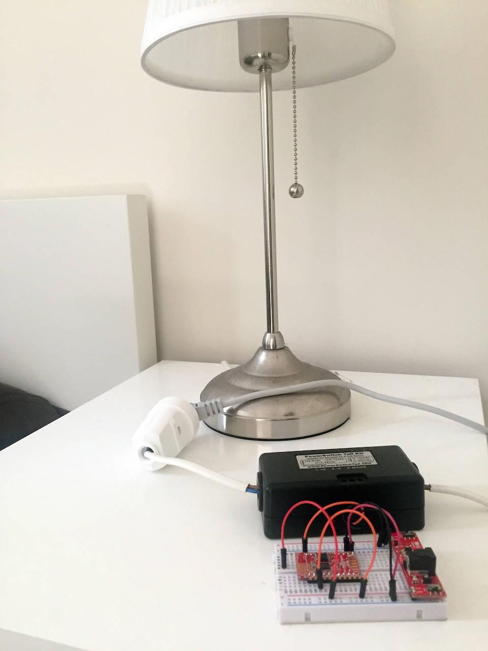
51 6.2 Hardware Configuration Again, please refer to the Getting Started with the ESP8266 book (or to the first chapters of this book) The only thing you need to add to this basic configuration is the PowerSwitch Tail Kit. Connect the two pins on the right (-in and Ground) on the ground of our project (blue power rail), and the +in pin to the GPIO5 pin. If your board doesn t have this pin, you can plug it to the free GPIO pin of your choice, you will just need to modify your code accordingly. Then, also connect a lamp or any electrical device to the PowerSwitch, and the other end of the PowerSwitch to the mains electricity. This is the assembled project, without the FTDI module to configure the module: And this is the project deployed close to the lamp I used as a test:
52
53 6.3 Controlling the Lamp Remotely We are now going to write the code required to control our lamp remotely. Note that we want a completely autonomous operation of the device. The ESP8266 will have to handle requests coming from your browser, display a simple HTML page with two buttons (On & Off), and then control the relay accordingly. As we are using the Arduino IDE to program our ESP8266 we will also be using the well-known Arduino language for this part. As the code is quite long, I will only cover the important parts here. Of course, you can find all the code inside the GitHub repository of the book. It starts by include the correct library: #include <ESP8266WiFi.h> Then, you need to enter your WiFi network & password: const char* ssid = "your_wifi_network"; const char* password = "your_wifi_password"; We also declare a web server running on port 80: WiFiServer server(80); We also declare that we will use GPIO pin 5. Of course if you are using another GPIO pin you will need to modify this value: int output_pin = 5; In the setup() function, we declare the pin on which the relay/powerswitch is connected: pinmode(output_pin, OUTPUT); After that, we connect to the WiFi network and start the server: WiFi.begin(ssid, password); while (WiFi.status()!= WL_CONNECTED) { delay(500); Serial.print("."); } Serial.println(""); Serial.println("WiFi connected"); // Start the server server.begin(); Serial.println("Server started"); Now, in the loop() function, we listen to incoming connections on port 80:
54 WiFiClient client = server.available(); free ebooks ==> When we receive some data, we first check if it doesn t contain the on or off values. If it does, we change the state of the output pin accordingly: if (req.indexof("/on")!= -1){ digitalwrite(output_pin, 1); } else if (req.indexof("/off")!= -1) { digitalwrite(output_pin, 0); } Now, we need to serve and display a basic interface every time we access the board via our browser. We will actually send all the HTML page, line by line. Let s start with the <head> element: String s = "HTTP/ OK\r\nContent-Type: text/html\r\n\r\n"; s += "<head>"; s += "<meta name=\"viewport\" content=\"width=device-width, initial-scale=1\">"; s += "<script src=\" s += "<link rel=\"stylesheet\" href=\" s += "bootstrap/3.3.4/css/bootstrap.min.css\">"; s += "</head>"; You can see that we even import modules like jquery (to handle the clicks on our buttons) and Bootstrap (to get a nice responsive interface). This is possible on the small ESP8266 chip because we are using the hosted versions of these frameworks, and therefore it doesn t take extra memory space on the chip. Then, we send the interface itself with two buttons: s += "<div class=\"container\">"; s += "<h1>relay Control</h1>"; s += "<div class=\"row\">"; s += "<div class=\"col-md-2\"><input class=\"btn btn-block btn-lg btn-primary\" "; s += "type=\"button\" value=\"on\" onclick=\"on()\"></div>"; s += "<div class=\"col-md-2\"><input class=\"btn btn-block btn-lg btn-danger\" "; s += "type=\"button\" value=\"off\" onclick=\"off()\"></div>"; s += "</div></div>"; This is also where you can give a name to our project. I put simply Relay Control as I was doing all the tests with a simple relay. Finally, we send some JavaScript code as well to handle the clicks on the buttons: s += "<script>function on() {$.get(\"/on\");}</script>"; s += "<script>function off() {$.get(\"/off\");}</script>"; Note that you can find all the code for this project on the corresponding GitHub repository:

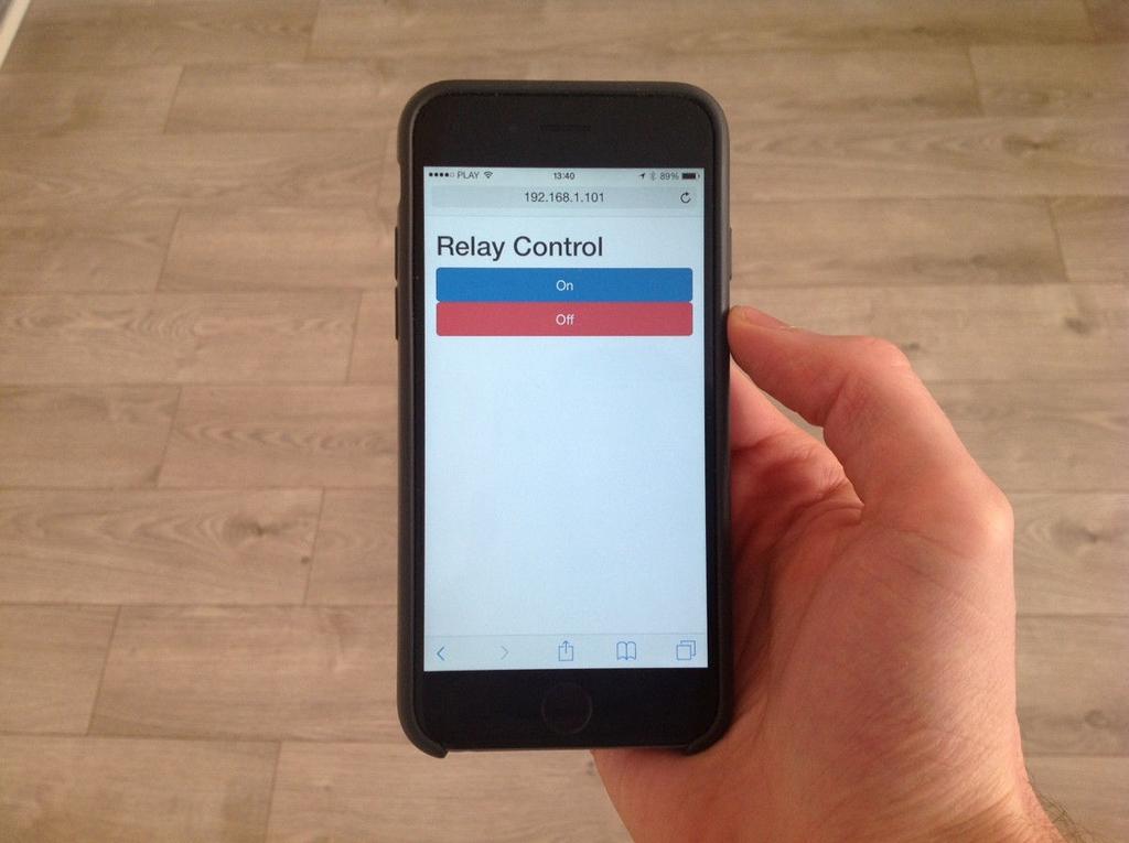
55 I used again the ESP8266 Arduino IDE software to upload files to the ESP8266 board. Then, open the Serial monitor to get the IP address of your board. Finally, simply open your favorite web browser, and type in the board IP address. You should see the interface being displayed: You can now try the buttons: you should notice that the state of the PowerSwitch or the relay is changing instantly, and that the lamp is turning on & off. And note that this is only using the ESP8266 chip here: it s completely independent from your computer! The interface is also responsive, thanks to the Bootstrap framework. This means it will automatically adapt to the device on which it is used. This is for example the result on my phone:
56
57 6.4 How to Go Further In this project, we built a completely autonomous remote lamp controller using the ESP8266 WiFi chip. We made this little chip control a lamp (or any other device) by serving a nice & responsive interface, allowing you to control the device from any terminal within your local WiFi network, like a phone or tablet. Of course, you can use what you learned in this project to build other home automation systems. You can for example use the same principles to add sensors to the project that measure data and display it all in a single interface, also served by the ESP8266 module.
58 Chapter 7 free ebooks ==> Create a Simple WiFi Alarm System In this chapter, we are going to build a simple alarm system based on the ESP8266. It will be composed of one or several ESP8266 modules coupled with motion sensors, and a central alarm interface running on your computer. Typically, motion detectors are using low-cost radios to communicate with a central alarm systems, and never WiFi. However, the ESP8266 chip is so cheap that it also makes sense here to use WiFi for motion sensors. Let s dive into the project!

59 7.1 Hardware & Software Requirements For this project, you will of course need an ESP8266 chip. As for the whole book, I used the Olimex ESP8266 module, but any ESP8266 module will work fine here. You will also need a motion sensor. I used a simple & cheap PIR motion sensor for this project. These are exactly the same kind of sensor that are used in commercial home automation systems: This is a list of all the components that will be used in this project: ESP8266 Olimex module ( ESP8266-DEV/) Breadboard 3.3V power supply ( 3.3V FTDI USB module ( PIR motion sensor ( Breadboard (
60 Jumper wires ( free ebooks ==> Also note that if you want to have several motion sensors like the one we are going to build here, you will need several ESP8266 chips & PIR sensors as well. As an example, we will only use one motion sensor for the project. On the software side, please refer to the Getting Started with the ESP8266 book (or to the first chapters of this book) to know which software components you need to get to make the ESP8266 chip work. At the end, you will need to have an ESP8266 chip ready to work with the ESP8266 Arduino IDE.

61 7.2 Hardware Configuration Again, please refer to the Getting Started with the ESP8266 book (or to the first chapters of this book). The only thing you will need to add in this project is the motion sensor. The PIR motion sensor is really easy to connect to the ESP8266 chip. First, connect the power supply: the VCC pin goes to the red power rail on the breadboard, and the GND pin of the sensor goes to the blue power rail. Finally, connect the SIG pin of the sensor to the GPIO pin 5 of the ESP8266 WiFi chip. This is the final result: Of course, you can also use another pin for the SIG pin, especially in case you are using an ESP8266 WiFi that doesn t have all the pins exposed. In that case, you will need to modify the code slightly.
62 7.3 Writing free ebooks the Motion ==> Sensor Code We are first going to write the sketch for the motion sensor. This code will basically constantly check the status of the motion sensor. If it detects that the state changed (which means motion has been detected), it will send a message to a web server running on your computer (that we will code later). As the code is quite long, I will only cover the important parts here. Of course, you can find all the code inside the GitHub repository of the book. We start by including the required library for the project: #include <ESP8266WiFi.h> Then, we define the IP address of the server that will run the alarm system. In this case, it is the IP address of your computer: const char* host = " "; There are many ways you can get it depending on your operating system, but it is usually found under a menu or panel called Network Preferences. We also initialize the motion sensor state to 0: int motion_sensor_state = 0; Then, in the loop() function of the sketch, we read data from the pin on which the motion sensor is connected: int new_motion_sensor_state = digitalread(5); Then, we compare this reading to the old reading, to see if the state changed: if (new_motion_sensor_state!= motion_sensor_state) If this is the case, we first assign the new state to the old state: motion_sensor_state = new_motion_sensor_state; Then, we create a client instant to connect to the server running on our computer: WiFiClient client; const int httpport = 3000; if (!client.connect(host, httpport)) { Serial.println("connection failed"); return; }
63 After that, we send a POST request to the server that contains the state of the sensor: client.print(string("post /motion?state=") + String(new_motion_sensor_state) + " HTTP/1.1\r\n" + "Host: " + host + "\r\n" + "Connection: close\r\n\r\n"); delay(10); After that, we read the answer from the server: while(client.available()){ String line = client.readstringuntil('\r'); Serial.print(line); } Note that you can find the whole sketch inside the GitHub repository of the book: It s now time to test the project. Get the code from the GitHub repository, modify it with your own parameters, and then upload the code to the board. Now, we can move to coding the alarm system itself.
64 7.4 Creating free ebooks Our ==> Alarm System We are now going to write the code for the alarm system, that will run on your computer. The server will be really basic: you will be able to monitor the state of the motion sensor from an interface, and also activate or deactivate the alarm mode. When the alarm mode will be activated, if motion is detected there will be a loud sound coming out of your computer. If it is deactivated, the sensor will keep on communicating with the server, but no sound will be emitted by the computer. We will use the very popular Node.js framework to code our server. You can now download it and install it from: There will basically be 3 files in this project: The app.js file, that will contain the code for the server itself The interface.jade file, that will define the interface The interface.js file, that will make the link between the interface & the server As the code is quite long, I will only cover the important parts here. Of course, you can find all the code inside the GitHub repository of the book. Let s start with the main file, which is called app.js. It starts by including the Express framework ( which will make it easier to code our web server: var express = require('express'); var app = express(); Then, we define some global variables: one for the state of the sensor, and for the state of the alarm: // Global variable for motion sensor var motion = 0; // Alarm state var alarm = 0; Then, we have to define various routes to get & to set the state of these variables: // Change motion sensor state app.post('/motion', function(req, res) { motion = req.query.state; res.send('data received: ' + motion); }); // Get motion sensor state
65 app.get('/motion', function(req, res) { res.json({state: motion}); }); // Get alarm state app.get('/alarm', function(req, res) { res.json({state: alarm}); }); // Set alarm state app.post('/alarm', function(req, res) { alarm = req.query.state; res.send('data received: ' + alarm); }); Finally, we start the web server with: app.listen(port); console.log("listening on port " + port); Now, let s see the interface.js file. This file will make the link between the interface and the server. We first define a function to query the value of the motion sensor, and change the interface accordingly. If motion is detected and the alarm is not on, we simply change the state of the indicator in the interface. If the alarm is on, we also play a sound. This is the complete code for this function: function refresh_motion() { $.getq('queue', '/motion', function(data) { if (data.state == 0) {$('#motion').html("no motion detected");} if (data.state == 1) { } } }); // Change text $('#motion').html("motion detected"); // Play sound if alarm is on $.get('/alarm', function(data) { if (data.state == 1) {$.playsound('/audio/alarm');} }); Now, we run this function every 500 milliseconds: refresh_motion(); setinterval(refresh_motion, 500); We also need to initialize a button for the alarm, and change the text & color of this button depending of the state of the alarm: $.get('/alarm', function(data) { var alarm_state = data.state; if (alarm_state == 1) { $('#alarm').html("alarm On"); $('#alarm').attr('class', 'btn btn-block btn-lg btn-success'); }
66 if (alarm_state == 0) { $('#alarm').html("alarm free ebooks Off"); ==> $('#alarm').attr('class', 'btn btn-block btn-lg btn-danger'); } }); Finally, we handle the clicks on the alarm button, and change the state of the alarm accordingly: $('#alarm').click(function() { // Get alarm state $.get('/alarm', function(data) { var alarm_state = data.state; if (alarm_state == 0) { $.post('/alarm?state=1'); $('#alarm').html("alarm On"); $('#alarm').attr('class', 'btn btn-block btn-lg btn-success'); } if (alarm_state == 1) { $.post('/alarm?state=0'); $('#alarm').html("alarm Off"); $('#alarm').attr('class', 'btn btn-block btn-lg btn-danger'); } }); }); Note that you can find all the code for this project inside the corresponding GitHub repository: It s now time to test the project. Get the code from the GitHub repository, and place all the files into a given folder. Then, go to this folder with a terminal. After that, type: sudo npm install express jade And then: node app.js Then, simply go to your favorite web browser, and type: You should see the interface of your simple alarm system, with the alarm off by default:

67 You can also now test the motion sensor. Just wave your hand in front of it, and you should see the text changing inside the interface. Now, try to click on the button. You should see that the button is turning green: Now, try to wave your hand in front of the sensor again. This time, you should hear a loud alarm sound coming from your computer. Congratulations, you now built a simple alarm system with the ESP8266 chip!
68 7.5 How free to ebooks Go Further ==> Let s summarize what we achieved in this chapter. We connected a PIR motion sensor to the ESP8266 chip, and then built a simple alarm system with it. There are many things you can do to improve this project. One way is to modify the code of this project slightly to accommodate for more motion sensors. On the ESP8266 side, you will need to for example assign an unique ID to each sensor and transmit this ID along with the state of the motion sensor. Then, on the server side, you will just need to get the ID of the sensor as well, and display the state of the different sensors inside the interface. You could also imagine connecting this project to Twitter, so you receive a Tweet every time motion is detected in your home.
69 Chapter 8 Build an Home Automation System Based on the ESP8266 For the final chapter of this book, we are going to integrate all the knowledge we acquired in the book so far to build a small home automation system that integrates several components. As an example, we will use again the temperature & humidity sensor project and the lamp control project, and integrate these projects into a single interface. This will allow you to monitor your home from a single interface. You will also be able to use what you learned in this project and add more components in the future.
70 8.1 Hardware free ebooks & ==> Software Requirements For this project, you basically need the same hardware that we used in two other projects of this book. For the temperature & humidity sensor module requirements, please check again Chapter 5. For the lamp control module requirements, please check again Chapter 6.
71 8.2 Hardware Configuration Again, to configure the hardware for this project, I will redirect you to the corresponding chapters of the book. For the temperature & humidity sensor module configuration, please check again Chapter 5. For the lamp control module configuration, please check again Chapter 6.
72 8.3 Writing free ebooks the Sketches ==> We are now going to write two sketches: one for the lamp control project, and one for the temperature & humidity sensor module. Compared to previous chapters, we don t want to have the ESP8266 WiFi serving it s own interface. Here, we just want these modules to respond to commands sent by a central server, that will run on our computer. To make things easier, we are going to use the arest API, which implements a RESTful interface for the ESP8266 board. Basically, it means that your board will be fully controllable via HTTP commands, for example coming from a web server. You can find more details about the project here: Now, we are going to start with the sketch to control the lamp. This is the complete sketch for this module: // Import required libraries #include <ESP8266WiFi.h> #include <arest.h> // Create arest instance arest rest = arest(); // WiFi parameters const char* ssid = "your_wifi_name"; const char* password = "your_wifi_password"; // The port to listen for incoming TCP connections #define LISTEN_PORT 80 // Create an instance of the server WiFiServer server(listen_port); void setup(void) { // Start Serial Serial.begin(115200); // Give name and ID to device rest.set_id("1"); rest.set_name("lamp_control"); // Connect to WiFi WiFi.begin(ssid, password); while (WiFi.status()!= WL_CONNECTED) { delay(500); Serial.print("."); } Serial.println(""); Serial.println("WiFi connected"); // Start the server server.begin(); Serial.println("Server started"); // Print the IP address Serial.println(WiFi.localIP());
73 } void loop() { } // Handle REST calls WiFiClient client = server.available(); if (!client) { return; } while(!client.available()){ delay(1); } rest.handle(client); Let s now see the important parts of this sketch. First, we need to include the ESP8266WiFi library and the arest library: #include <ESP8266WiFi.h> #include <arest.h> Then, we create an instance of the arest library: arest rest = arest(); In the loop() function of the sketch, we check if we have a client connected to the ESP8266. If that s the case, we handle the request with the arest library: // Handle REST calls WiFiClient client = server.available(); if (!client) { return; } while(!client.available()){ delay(1); } rest.handle(client); It s now time to test the project. Get the code from the GitHub repository, modify it with your own parameters, and then upload the code to the board. Now, open the Serial monitor to get the IP address of the board. We ll assume for the rest of this section that it is Then, go to your favorite web browser, and type: This command will set the GPIO pin 5 to an output. Then, type: This is the command to turn the GPIO pin 5 to a HIGH state. As soon as you press this command, the LED should turn on. You should also receive a confirmation message in your browser. You can of course just put a 0 at the end of the command to turn it off again.
74 We are now going to see the sketch for the temperature & humidity sensor module. This is the complete sketch free for this ebooks part: ==> // Import required libraries #include <ESP8266WiFi.h> #include <arest.h> #include "DHT.h" // Pin #define DHTPIN 5 // Use DHT11 sensor #define DHTTYPE DHT11 // Initialize DHT sensor DHT dht(dhtpin, DHTTYPE, 15); // Create arest instance arest rest = arest(); // WiFi parameters const char* ssid = "your_wifi_name"; const char* password = "your_wifi_password"; // The port to listen for incoming TCP connections #define LISTEN_PORT 80 // Create an instance of the server WiFiServer server(listen_port); // Variables float temperature; float humidity; void setup(void) { // Start Serial Serial.begin(115200); } // Give name and ID to device rest.set_id("2"); rest.set_name("sensor"); // Expose variables to API rest.variable("temperature", &temperature); rest.variable("humidity", &humidity); // Connect to WiFi WiFi.begin(ssid, password); while (WiFi.status()!= WL_CONNECTED) { delay(500); Serial.print("."); } Serial.println(""); Serial.println("WiFi connected"); // Start the server server.begin(); Serial.println("Server started"); // Print the IP address Serial.println(WiFi.localIP()); // Init DHT dht.begin(); void loop() { // Reading temperature and humidity humidity = dht.readhumidity(); // Read temperature as Celsius
75 temperature = dht.readtemperature(); // Handle REST calls WiFiClient client = server.available(); if (!client) { return; } while(!client.available()){ delay(1); } rest.handle(client); } As the code is quite long, I will only go through the important parts that we added compared to the previous sketch. Just as before, we need to give an ID and a name to our module: rest.set_id("2"); rest.set_name("sensor"); Here, what we want to do is to query for the value of the temperature & humidity of the board. This is done with the variable() function: rest.variable("temperature", &temperature); rest.variable("humidity", &humidity); It s now time to test the project. Get the code from the GitHub repository, modify it with your own parameters, and then upload the code to the board. Then, open the Serial monitor to get the IP address of this module. Let s assume here it is Now, go to a web browser and type: You will then receive an answer from the board with the value of the temperature: {"temperature": 22, "id": "2", "name": "sensor", "connected": true} You can of course do the same with the humidity. Congratulations, you now have two working modules in your home automation system based on the ESP8266!
76 8.4 Creating free ebooks the ==> Interface We are now going to code the interface that you will use to control all the modules from a central interface. As in the previous chapter, we will use the very popular Node.js framework to code our server. You can now download it and install it from: There will basically be 3 files in this project: The app.js file, that will contain the code for the server itself The interface.jade file, that will define the interface The interface.js file, that will make the link between the interface & the server Let s first see the app.js file. We start by declaring the Express framework: var express = require('express'); var app = express(); We also set the port to 3000: var port = 3000; After that, we set the view engine to Jade, which we will use to code the interface in a very simple way: app.set('view engine', 'jade'); Then, we define the main route of the interface, which we will use to access the interface of the home automation system: app.get('/', function(req, res){ res.render('interface'); }); In this project will also use the arest Node.js module, that will make the link between the server running on your computer and all the modules we created before. This is how to use it in the app: var rest = require("arest")(app); Then, we add both devices into the app:
77 rest.adddevice('http',' '); rest.adddevice('http',' '); Of course, you will need to change these IP addresses depending on the IP addresses of your modules. Finally, we start the app with: app.listen(port); console.log("listening on port " + port); Now, let s see the content of the interface.jade file. This will define the interface and all the components in it. First, we need to include the Bootstrap CSS framework that we used in previous chapters of this book. We also include jquery. This is all defined in this piece of code: head title Interface link(rel='stylesheet', href=" link(rel='stylesheet', href="/css/interface.css") meta(name='viewport', content='width=device-width, initial-scale=1') script(src=" script(src="/js/ajaxq.js") script(src="/js/interface.js") Then, we define the interface itself in the body tag. We basically create two buttons to control the module with the LED (called lamp control here), and then we create two indicators for the temperature & humidity module: body.container h1 Dashboard.row.voffset.col-md-4 div Lamp Control.col-md-4 button.btn.btn-block.btn-lg.btn-primary#1 On.col-md-4 button.btn.btn-block.btn-lg.btn-danger#2 Off.row.voffset.col-md-4 div#temperature Temperature:.col-md-4 div#humidity Humidity: Let s now see the interface.js file, which will make the link between the interface and the server. We first need to set the GPIO pin 5 as an output with the following command: $.getq('queue', '/lamp_control/mode/5/o'); Then, we create two functions that will handle the clicks on the buttons in the interface: $("#1").click(function() {
; }); Finally, we define a function to refresh the temperature & humidity readings. We also repeat this function every 10 seconds: function refresh_dht() { $.")
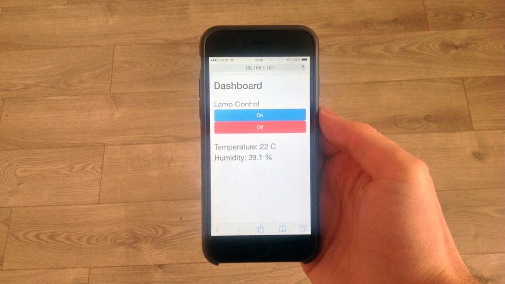
78 $.getq('queue', '/lamp_control/digital/5/1'); }); free ebooks ==> $("#2").click(function() { $.getq('queue', '/lamp_control/digital/5/0'); }); Finally, we define a function to refresh the temperature & humidity readings. We also repeat this function every 10 seconds: function refresh_dht() { $.getq('queue', '/sensor/temperature', function(data) { $('#temperature').html("temperature: " + data.temperature + " C"); }); $.getq('queue', '/sensor/humidity', function(data) { $('#humidity').html("humidity: " + data.humidity + " %"); }); } refresh_dht(); setinterval(refresh_dht, 10000); It s now time to test the project. Get the code from the GitHub repository, modify it with your own parameters, and then upload the code to the board. Then, go to the folder where the app.js file is located, and type: sudo npm install arest jade express Then, launch the app with: node app.js After that, go to your favorite browser and type: You should immediately see the interface of your home automation system: You can already try pressing the button, it should switch the LED on your ESP8266 project on & off. Of course, you can use the exact same interface to control a lamp that would be connected to it for example. Note that this interface is also fully responsive, which means you can access it from your phone or tablet. This is the result on my phone:
79
How to use an ESP-01S module
 How to use an ESP-01S module How Does It Work? The ESP8266 can be controlled from your local Wi-Fi network or from the internet (after port forwarding). The ESP-01 module has GPIO pins that can be programmed
Home Automation With Arduino
 Home Automation With Arduino Automate Your Home Using Open-Source Hardware Marco Schwartz, PhD Contents Legal Acknowledgments About the author About the companion website Preface to the First Edition Preface
Monitor your home remotely using the Arduino
 Monitor your home remotely using the Arduino WiFi Shield How to monitor some data in your home using precisely this Arduino WiFi shield. Along with the Arduino Uno board, the final system will form an
Make a Simple Weather Station Using Arduino
 Make a Simple Weather Station Using Arduino In this article, you will learn how to build your own weather station using the Arduino platform. This tutorial is based on the work from Steve Spence from Arduinotronics,
Remote Control with the Huzzah + Adafruit.io
 Remote Control with the Huzzah + Adafruit.io Created by Richard Albritton Last updated on 2017-07-30 03:11:01 PM UTC Guide Contents Guide Contents Overview Adafruit IO Setup Creating the Buttons Feed Adding
Adafruit CC3000 WiFi and Xively
 Adafruit CC3000 WiFi and Xively Created by Marc-Olivier Schwartz Last updated on 2018-08-22 03:37:52 PM UTC Guide Contents Guide Contents Introduction Setting up your Xively account Connections DHT11 sensor
Create your own wireless motion sensor with
 Create your own wireless motion sensor with Arduino If you have a friend that has an alarm system in his or her home, I am sure you ve all seen these white motion sensors that are usually fixed above doors
DIY Korner home security system
 DIY Korner home security system What is Korner security system? This product is meant for home security. It comes with a korner tag (korner stick) and several korner tags. The one to the right is the korner
ESP32 WIFI/BLE Board v0.9
 ESP32 WIFI/BLE Board v0.9 From Elecrow Contents 1 Introduction 2 Feactures 3 Specification 4 Interface Function 5 Usage 5.1 Installing the ESP32 Arduino Core 5.1.1 Download the Core 5.1.2 Install the Xtensa
Sten-SLATE ESP. WiFi
 Sten-SLATE ESP WiFi Stensat Group LLC, Copyright 2016 1 References www.arduino.cc http://esp8266.github.io/arduino/versions/2.1.0/doc/reference.html 2 Introduction The wifi integrated in the processor
Note. The above image and many others are courtesy of - this is a wonderful resource for designing circuits.
 Robotics and Electronics Unit 2. Arduino Objectives. Students will understand the basic characteristics of an Arduino Uno microcontroller. understand the basic structure of an Arduino program. know how
Guide to practical classes in IoT design and integration
 Guide to practical classes in IoT design and integration for students in Computer Science Introduction This experimental teaching module is first of the kind taught in our department. The study is based
StenBOT Robot Kit. Stensat Group LLC, Copyright 2018
 StenBOT Robot Kit 1 Stensat Group LLC, Copyright 2018 Legal Stuff Stensat Group LLC assumes no responsibility and/or liability for the use of the kit and documentation. There is a 90 day warranty for the
ESP8266 Weather Station User Guide V 1.0 Mar 2017
 ESP8266 Weather Station User Guide V 1.0 Mar 2017 Contents 1. Introduction...4 2. Assembly...5 A. ESP8266 Module...5 B. OLED Display...6 C. DHT11 Humidity & Temperature Sensor...7 D. Wires & Cables...8
ipot Phase 1 1
 ipot Phase 1 Contents Introduction... 3 Step 1: Connect the Soil Humidity Hygrometer Moisture sensor... 5 Step 2: Connect DHT22 Humidity and Temperature sensor... 8 Step 3: Connecting OLED U8glib screen...
ESP8266 Weather Station
 ESP8266 Weather Station Getting Started Guide Daniel Eichhorn This book is for sale at http://leanpub.com/esp8266weatherstationgettingstartedguide This version was published on 2017-02-10 This is a Leanpub
Internet of Things with Arduino
 Internet of Things with Arduino Build Internet of Things Projects With the Arduino Platform Marco Schwartz, PhD Contents Legal Introduction 1 Why the Internet of Things? 2 How is the book organized? 3
Hardware Overview. Onboard Sensors. Pressure, Humidity, and Temperature. Air Quality and Temperature
 Hardware Overview The ESP32 Environment Sensor Shield incorporates three sensors capable of measuring five different environmental variables. It also provides connections for several other sensors that
Responsive Web Design and Bootstrap MIS Konstantin Bauman. Department of MIS Fox School of Business Temple University
 Responsive Web Design and Bootstrap MIS 2402 Konstantin Bauman Department of MIS Fox School of Business Temple University Exam 3 (FINAL) Date: 12/06/18 four weeks from now! JavaScript, jquery, Bootstrap,
University of Hull Department of Computer Science C4DI Interfacing with Arduinos
 Introduction Welcome to our Arduino hardware sessions. University of Hull Department of Computer Science C4DI Interfacing with Arduinos Vsn. 1.0 Rob Miles 2014 Please follow the instructions carefully.
Lab 01 Arduino 程式設計實驗. Essential Arduino Programming and Digital Signal Process
 Lab 01 Arduino 程式設計實驗 Essential Arduino Programming and Digital Signal Process Arduino Arduino is an open-source electronics prototyping platform based on flexible, easy-to-use hardware and software. It's
Adafruit 1-Wire Thermocouple Amplifier - MAX31850K
 Adafruit 1-Wire Thermocouple Amplifier - MAX31850K Created by lady ada Last updated on 2018-08-22 03:40:09 PM UTC Guide Contents Guide Contents Overview Pinouts Power Pins Address Pins Data Pin Themocouple
Adafruit HUZZAH ESP8266 breakout
 Adafruit HUZZAH ESP8266 breakout Created by lady ada Last updated on 2017-11-20 08:42:12 PM UTC Guide Contents Guide Contents Overview Pinouts Power Pins Serial pins GPIO pins Analog Pins Other control
ESP8266 Thing Development Board Hookup Guide
 Page 1 of 28 ESP8266 Thing Development Board Hookup Guide Introduction The ESP8266 is a cost-effective, and very capable WiFi-enabled microcontroller. Like any microcontroller, it can be programmed to
Adafruit 1-Wire Thermocouple Amplifier - MAX31850K
 Adafruit 1-Wire Thermocouple Amplifier - MAX31850K Created by lady ada Last updated on 2015-04-09 03:45:15 PM EDT Guide Contents Guide Contents Overview Pinouts Power Pins Address Pins Data Pin Themocouple
Electronic Brick Starter Kit
 Electronic Brick Starter Kit Getting Started Guide v1.0 by Introduction Hello and thank you for purchasing the Electronic Brick Starter Pack from Little Bird Electronics. We hope that you will find learning
Documentation for Wifi-Enabled Data Logging - System Control By: Jesse Jenkins
 Documentation for Wifi-Enabled Data Logging - System Control By: Jesse Jenkins Code for this project is found on Github: https://github.com/hedronuser/metabolizer For getting started with Blynk, check
#include "DHT.h" DHT dht(dhtpin, DHTTYPE); // Date and time functions using a DS1307 RTC connected via I2C and Wire lib
; // Date and time functions using a DS1307 RTC connected via I2C and Wire lib") #include "DHT.h" #define DHTPIN 2 // what pin we're connected to // Uncomment whatever type you're using! #define DHTTYPE DHT11 // DHT 11 //#define DHTTYPE DHT22 // DHT 22 (AM2302) //#define DHTTYPE DHT21
#include "DHT.h" #define DHTPIN 2 // what pin we're connected to // Uncomment whatever type you're using! #define DHTTYPE DHT11 // DHT 11 //#define DHTTYPE DHT22 // DHT 22 (AM2302) //#define DHTTYPE DHT21
Sten-SLATE ESP. Simple Web Server
 Sten-SLATE ESP Simple Web Server Stensat Group LLC, Copyright 2018 1 References www.arduino.cc https://github.com/esp8266/arduino 2 System Design A web server uses the client/server software model. The
Robotics/Electronics Review for the Final Exam
 Robotics/Electronics Review for the Final Exam Unit 1 Review. 1. The battery is 12V, R1 is 400 ohms, and the current through R1 is 20 ma. How many ohms is R2? ohms What is the voltage drop across R1? V
This project will use an API from to retrieve a list of movie posters to display on screen.
 Getting Started 1. Go to http://quickdojo.com 2. Click this: Project Part 1 (of 2) - Movie Poster Lookup Time to put what you ve learned to action. This is a NEW piece of HTML, so start quickdojo with
Adafruit BME680. Created by lady ada. Last updated on :10:23 AM UTC
 Adafruit BME680 Created by lady ada Last updated on 2018-01-22 05:10:23 AM UTC Guide Contents Guide Contents Overview Pinouts Power Pins: SPI Logic pins: I2C Logic pins: Assembly Prepare the header strip:
Adafruit HUZZAH ESP8266 breakout
 Adafruit HUZZAH ESP8266 breakout Created by lady ada Last updated on 2016-10-10 04:15:10 PM UTC Guide Contents Guide Contents Overview Pinouts Power Pins Serial pins GPIO pins Analog Pins Other control
This tutorial will show you how to take temperature readings using the Freetronics temperature sensor and an Arduino Uno.
 This tutorial will show you how to take temperature readings using the Freetronics temperature sensor and an Arduino Uno. Note that there are two different module types: the temperature sensor module and
Overview. Multiplexor. cs281: Introduction to Computer Systems Lab02 Basic Combinational Circuits: The Mux and the Adder
 cs281: Introduction to Computer Systems Lab02 Basic Combinational Circuits: The Mux and the Adder Overview The objective of this lab is to understand two basic combinational circuits the multiplexor and
Troubleshooting Guide for the ESP8266
 Troubleshooting Guide for the ESP8266 The ESP8266 has a few common issues, especially when you are trying to flash a new firmware or uploading scripts. This is a companion guide to the Home Automation
Adafruit 1-Wire GPIO Breakout - DS2413
 Adafruit 1-Wire GPIO Breakout - DS2413 Created by Bill Earl Last updated on 2018-08-22 03:40:00 PM UTC Guide Contents Guide Contents Overview Assembly & Wiring Headers Position the Header And Solder! Wiring
Introduction To Arduino
 Introduction To Arduino What is Arduino? Hardware Boards / microcontrollers Shields Software Arduino IDE Simplified C Community Tutorials Forums Sample projects Arduino Uno Power: 5v (7-12v input) Digital
Adapted from a lab originally written by Simon Hastings and Bill Ashmanskas
 Physics 364 Arduino Lab 1 Adapted from a lab originally written by Simon Hastings and Bill Ashmanskas Vithayathil/Kroll Introduction Last revised: 2014-11-12 This lab introduces you to an electronic development
Laboratory 1 Introduction to the Arduino boards
 Laboratory 1 Introduction to the Arduino boards The set of Arduino development tools include µc (microcontroller) boards, accessories (peripheral modules, components etc.) and open source software tools
Arduino: LCD Diagrams & Code Brown County Library
 Arduino: LCD Diagrams & Code Project 01: Hello, World! Components needed: Arduino Uno board breadboard 16 jumper wires 16x2 LCD screen 10k potentiometer /* LCD 01 : Hello World! Source: Code adapted from
Serial.begin ( ); Serial.println( ); analogread ( ); map ( );
; Serial.println( ); analogread ( ); map ( );") Control and Serial.begin ( ); Serial.println( ); analogread ( ); map ( ); A system output can be changed through the use of knobs, motion, or environmental conditions. Many electronic systems in our world
Control and Serial.begin ( ); Serial.println( ); analogread ( ); map ( ); A system output can be changed through the use of knobs, motion, or environmental conditions. Many electronic systems in our world
Design and Implementation of Modern Greenhouse System
 Design and Implementation of Modern Greenhouse System Zaw Ngwe Lecturer, Department of Electronic Engineering Technological University (Mandalay) Mandalay City, Myanmar Email - zawngwe278@gmail.com Abstract:
AT42QT1010 Capacitive Touch Breakout Hookup Guide
 Page 1 of 7 AT42QT1010 Capacitive Touch Breakout Hookup Guide Introduction If you need to add user input without using a button, then a capacitive touch interface might be the answer. The AT42QT1010 Capacitive
1/Build a Mintronics: MintDuino
 1/Build a Mintronics: The is perfect for anyone interested in learning (or teaching) the fundamentals of how micro controllers work. It will have you building your own micro controller from scratch on
Arduino 101 AN INTRODUCTION TO ARDUINO BY WOMEN IN ENGINEERING FT T I NA A ND AW E S O ME ME NTO R S
 Arduino 101 AN INTRODUCTION TO ARDUINO BY WOMEN IN ENGINEERING FT T I NA A ND AW E S O ME ME NTO R S Overview Motivation Circuit Design and Arduino Architecture Projects Blink the LED Switch Night Lamp
Arduino Android Blueprints
 Arduino Android Blueprints Get the best out of Arduino by interfacing it with Android to create engaging interactive projects Marco Schwartz Stefan Buttigieg BIRMINGHAM - MUMBAI Arduino Android Blueprints
EEG 101L INTRODUCTION TO ENGINEERING EXPERIENCE
 EEG 101L INTRODUCTION TO ENGINEERING EXPERIENCE LABORATORY 1: INTRODUCTION TO ARDUINO IDE AND PROGRAMMING DEPARTMENT OF ELECTRICAL AND COMPUTER ENGINEERING UNIVERSITY OF NEVADA, LAS VEGAS 1. FYS KIT COMPONENTS
Lab 2 - Powering the Fubarino. Fubarino,, Intro to Serial, Functions and Variables
 Lab 2 - Powering the Fubarino Fubarino,, Intro to Serial, Functions and Variables Part 1 - Powering the Fubarino SD The Fubarino SD is a 56 pin device. Each pin on a chipkit device falls broadly into one
Adafruit Feather HUZZAH ESP8266
 Adafruit Feather HUZZAH ESP8266 Created by lady ada Last updated on 2018-01-11 03:27:01 PM UTC Guide Contents Guide Contents Overview Pinouts Power Pins Logic pins Serial pins I2C & SPI pins GPIO pins
Smart Objects. SAPIENZA Università di Roma, M.Sc. in Product Design Fabio Patrizi
 Smart Objects SAPIENZA Università di Roma, M.Sc. in Product Design Fabio Patrizi 1 What is a Smart Object? Essentially, an object that: Senses Thinks Acts 2 Example 1 https://www.youtube.com/watch?v=6bncjd8eke0
AT42QT101X Capacitive Touch Breakout Hookup Guide
 Page 1 of 10 AT42QT101X Capacitive Touch Breakout Hookup Guide Introduction If you need to add user input without using a button, then a capacitive touch interface might be the answer. The AT42QT1010 and
Sten-SLATE ESP Kit. Description and Programming
 Sten-SLATE ESP Kit Description and Programming Stensat Group LLC, Copyright 2016 Overview In this section, you will be introduced to the processor board electronics and the arduino software. At the end
Adafruit Feather HUZZAH ESP8266
 Adafruit Feather HUZZAH ESP8266 Created by lady ada Last updated on 2016-03-19 08:43:43 PM EDT Guide Contents Guide Contents Overview Pinouts Power Pins Logic pins Serial pins I2C & SPI pins GPIO pins
CHAPTER V IMPLEMENTATION AND TESTING
 CHAPTER V IMPLEMENTATION AND TESTING 5.1 Implementation 5.1.1 Arduino IDE This project uses the arduino IDE application. This application used to compile and to upload the program. The program can be seen
Introduction to Internet of Things Prof. Sudip Misra Department of Computer Science & Engineering Indian Institute of Technology, Kharagpur
 Introduction to Internet of Things Prof. Sudip Misra Department of Computer Science & Engineering Indian Institute of Technology, Kharagpur Lecture - 30 Implementation of IoT with Raspberry Pi- I In the
Arduino - DigitalReadSerial
 arduino.cc Arduino - DigitalReadSerial 5-6 minutes Digital Read Serial This example shows you how to monitor the state of a switch by establishing serial communication between your Arduino or Genuino and
Digital Pins and Constants
 Lesson Lesson : Digital Pins and Constants Digital Pins and Constants The Big Idea: This lesson is the first step toward learning to connect the Arduino to its surrounding world. You will connect lights
Quick.JS Documentation
 Quick.JS Documentation Release v0.6.1-beta Michael Krause Jul 22, 2017 Contents 1 Installing and Setting Up 1 1.1 Installation................................................ 1 1.2 Setup...................................................
Adafruit BMP280 Barometric Pressure + Temperature Sensor Breakout
 Adafruit BMP280 Barometric Pressure + Temperature Sensor Breakout Created by lady ada Last updated on 2017-12-09 06:21:37 PM UTC Guide Contents Guide Contents Overview Pinouts Power Pins: SPI Logic pins:
(128x64dot) Wi-Fi (CPU ESP-WROOM-02) Susumu Shikata V2: V3: SPIFF SSID / Password / IP " "
 Wi-Fi (CPU ESP-WROOM-02) Susumu Shikata V2: V3: SPIFF SSID / Password / IP") /* (128x64dot) Wi-Fi (CPU ESP-WROOM-02) Susumu Shikata V2:2017.10.22 GPIO0 ( ) V3:2017.11.21 SPIFF SSID / Password / IP ) 4 "1" "255.255.255.0" ------------------------------ https:qiita.com/exabugs/items/2f67ae363a1387c8967c
/* (128x64dot) Wi-Fi (CPU ESP-WROOM-02) Susumu Shikata V2:2017.10.22 GPIO0 ( ) V3:2017.11.21 SPIFF SSID / Password / IP ) 4 "1" "255.255.255.0" ------------------------------ https:qiita.com/exabugs/items/2f67ae363a1387c8967c
micro:bit Lesson 2. Controlling LEDs on Breadboard
 micro:bit Lesson 2. Controlling LEDs on Breadboard Created by Simon Monk Last updated on 2018-03-09 02:39:14 PM UTC Guide Contents Guide Contents Overview Parts BBC micro:bit Half-size breadboard Small
Arduino Platform Part I
 Arduino Platform Part I Justin Mclean Class Software Email: justin@classsoftware.com Twitter: @justinmclean Blog: http://blog.classsoftware.com Who am I? Director of Class Software for almost 15 years
Parts List. XBEE/Wifi Adapter board 4 standoffs ¼ inch screws Cable XBEE module or Wifi module
 Rover Wifi Module 1 Legal Stuff Stensat Group LLC assumes no responsibility and/or liability for the use of the kit and documentation. There is a 90 day warranty for the Sten-Bot kit against component
Building your own special-purpose embedded system gadget.
 Bare-duino Building your own special-purpose embedded system gadget. Saves a little money. You can configure the hardware exactly the way that you want. Plus, it s fun! bare-duino 1 Arduino Uno reset I/O
STT41AS1 v7.0 FUNCTIONAL DESCRIPTION
 All things connected Snaptekk www.snaptekk.com The WiFi Wireless Ham Radio Coax Antenna Switch allows a single transceiver to switch between 4 antennas or 4 transceivers to switch to a single antenna.
Procedure: Determine the polarity of the LED. Use the following image to help:
 Section 2: Lab Activity Section 2.1 Getting started: LED Blink Purpose: To understand how to upload a program to the Arduino and to understand the function of each line of code in a simple program. This
Front-End UI: Bootstrap
 Responsive Web Design BootStrap Front-End UI: Bootstrap Responsive Design and Grid System Imran Ihsan Assistant Professor, Department of Computer Science Air University, Islamabad, Pakistan www.imranihsan.com
SX1509 I/O Expander Breakout Hookup Guide
 Page 1 of 16 SX1509 I/O Expander Breakout Hookup Guide Introduction Is your Arduino running low on GPIO? Looking to control the brightness of 16 LEDs individually? Maybe blink or breathe a few autonomously?
RedBoard Hookup Guide
 Page 1 of 11 RedBoard Hookup Guide CONTRIBUTORS: JIMB0 Introduction The Redboard is an Arduino-compatible development platform that enables quick-and-easy project prototyping. It can interact with real-world
One Grove Base Shield board this allows you to connect various Grove units (below) to your Seeeduino board; Nine Grove Grove units, consisting of:
 to your Seeeduino board; Nine Grove Grove units, consisting of:") GROVE - Starter Kit V1.0b Introduction The Grove system is a modular, safe and easy to use group of items that allow you to minimise the effort required to get started with microcontroller-based experimentation
GROVE - Starter Kit V1.0b Introduction The Grove system is a modular, safe and easy to use group of items that allow you to minimise the effort required to get started with microcontroller-based experimentation
4Serial SIK BINDER //77
 4Serial SIK BINDER //77 SIK BINDER //78 Serial Communication Serial is used to communicate between your computer and the RedBoard as well as between RedBoard boards and other devices. Serial uses a serial
We are assuming you have node installed!
 Node.js Hosting We are assuming you have node installed! This lesson assumes you've installed and are a bit familiar with JavaScript and node.js. If you do not have node, you can download and install it
Adafruit VL53L0X Time of Flight Micro-LIDAR Distance Sensor Breakout
 Adafruit VL53L0X Time of Flight Micro-LIDAR Distance Sensor Breakout Created by lady ada Last updated on 2016-12-05 06:40:45 PM UTC Guide Contents Guide Contents Overview Sensing Capablities Pinouts Power
Prototyping & Engineering Electronics Kits Basic Kit Guide
 Prototyping & Engineering Electronics Kits Basic Kit Guide odysseyboard.com Please refer to www.odysseyboard.com for a PDF updated version of this guide. Guide version 1.0, February, 2018. Copyright Odyssey
EXPERIMENT 7 Please visit https://www.arduino.cc/en/reference/homepage to learn all features of arduino before you start the experiments
 EXPERIMENT 7 Please visit https://www.arduino.cc/en/reference/homepage to learn all features of arduino before you start the experiments TEMPERATURE MEASUREMENT AND CONTROL USING LM35 Purpose: To measure
Adafruit DS3231 Precision RTC Breakout
 Adafruit DS3231 Precision RTC Breakout Created by lady ada Last updated on 2016-02-05 04:43:25 PM EST Guide Contents Guide Contents Overview Pinouts Power Pins: I2C Logic pins: Other Pins: Assembly Prepare
FireBeetle ESP8266 IOT Microcontroller SKU: DFR0489
 FireBeetle ESP8266 IOT Microcontroller SKU: DFR0489 Introduction DFRobot FireBeetle is a series of low-power-consumption development hardware designed for Internet of Things (IoT). Firebeetle ESP8266 is
keyestudio Keyestudio MEGA 2560 R3 Board
 Keyestudio MEGA 2560 R3 Board Introduction: Keyestudio Mega 2560 R3 is a microcontroller board based on the ATMEGA2560-16AU, fully compatible with ARDUINO MEGA 2560 REV3. It has 54 digital input/output
Acknowledgments...xvi Introduction... xvii Primer Project 1: Blinking an LED Project 2: Pushbutton LED Flashlight...
 Contents Acknowledgments...xvi Introduction... xvii Primer... 2 LEDs Project 1: Blinking an LED... 36 Project 2: Pushbutton LED Flashlight... 46 Project 3: LED Dimmer Switch... 52 Project 4: A Graphical
BASIC Arduino. Part I
 BASIC Arduino Part I Objectives Introduction to Arduino Build a 1-60MHz DDS VFO prototype, breadboard and write Sketches, with Buffer amps to be designed, and PCB Using your own laptop Go on to build other
Robotics and Electronics Unit 5
 Robotics and Electronics Unit 5 Objectives. Students will work with mechanical push buttons understand the shortcomings of the delay function and how to use the millis function. In this unit we will use
Rotary Encoder Basics
 Rotary Encoder Basics A rotary encoder has a fixed number of positions per revolution. These positions are easily felt as small clicks you turn the encoder. The Keyes module that I have has thirty of these
VKey Voltage Keypad Hookup Guide
 Page 1 of 8 VKey Voltage Keypad Hookup Guide Introduction If you need to add a keypad to your microcontroller project, but don t want to use up a lot of I/O pins to interface with it, the VKey is the solution
Halloween Pumpkinusing. Wednesday, October 17, 12
 Halloween Pumpkinusing Blink LED 1 What you will need: 1 MSP-EXP430G2 1 3 x 2 Breadboard 3 560 Ohm Resistors 3 LED s (in Red Color Range) 3 Male to female jumper wires 1 Double AA BatteryPack 2 AA Batteries
ESPixelStick V2 Assembly and Usage
 ESPixelStick V2 Assembly and Usage OVERVIEW The ESPixelStick is a wireless (802.11g/n) pixel controller that interfaces as a standard sacn / E1.31 controller and supports a variety of pixel types. It also
Beyond the Blink: Add Drupal to Your IoT Playground. Amber Matz
 Beyond the Blink: Add Drupal to Your IoT Playground Amber Matz Hi. I m Amber. Name: Amber Matz (neé Himes) Drupal.org username: Amber Himes Matz Twitter: @amberhimesmatz My job: Production Manager and
User Manual. ESP8266 Wifi Shield
 User Manual Of ESP8266 Wifi Shield Description The shield is designed based on esp8266 by Espressif Systems, pin-compatible with Arduino UNO/Mega2560 DevBorad. Which can be used as two independent part,
Bosch BMP085 Breakout Board
 Bosch BMP085 Breakout Board Created by lady ada Last updated on 2014-11-07 03:00:29 PM EST Guide Contents Guide Contents Overview Specifications Wiring the BMP085 Using the BMP085 (API v2) Using the BMP085
IME-100 ECE. Lab 3. Electrical and Computer Engineering Department Kettering University. G. Tewolde, IME100-ECE,
 IME-100 ECE Lab 3 Electrical and Computer Engineering Department Kettering University 3-1 1. Laboratory Computers Getting Started i. Log-in with User Name: Kettering Student (no password required) ii.
Parts List. XBEE/Wifi Adapter board 4 standoffs ¼ inch screws Cable XBEE module or Wifi module
 Rover Wifi Module 1 Legal Stuff Stensat Group LLC assumes no responsibility and/or liability for the use of the kit and documentation. There is a 90 day warranty for the Sten-Bot kit against component
Lab 8. Communications between Arduino and Android via Bluetooth
 Lab 8. Communications between Arduino and Android via Bluetooth Dr. X. Li xhli@citytech.cuny.edu Dept. of Computer Engineering Technology New York City College of Technology (Copyright Reserved) In this
Si4703 FM Radio Receiver Hookup Guide
 Page 1 of 5 Si4703 FM Radio Receiver Hookup Guide Introduction This breakout board enables you to tune in to FM radio stations, using the Si4703 FM tuner chip from Silicon Laboratories. This IC also works
Adafruit BME280 Humidity + Barometric Pressure + Temperature Sensor Breakout
 Adafruit BME280 Humidity + Barometric Pressure + Temperature Sensor Breakout Created by lady ada Last updated on 2018-08-22 03:49:22 PM UTC Guide Contents Guide Contents Overview Pinouts Power Pins: SPI
A Hacker s Introduction to the Nokia N900
 A Hacker s Introduction to the Nokia N900 Introduction Welcome to the Hacker s Introduction to the Nokia N900. This guide is intended to help you begin connecting the N900 s builtin capabilities to information
Arduino Prof. Dr. Magdy M. Abdelhameed
 Course Code: MDP 454, Course Name:, Second Semester 2014 Arduino What is Arduino? Microcontroller Platform Okay but what s a Microcontroller? Tiny, self-contained computers in an IC Often contain peripherals
CTEC 1802 Embedded Programming Labs
 CTEC 1802 Embedded Programming Labs This document is intended to get you started using the Arduino and our I/O board in the laboratory - and at home! Many of the lab sessions this year will involve 'embedded
Lesson 8: Digital Input, If Else
 Lesson 8 Lesson 8: Digital Input, If Else Digital Input, If Else The Big Idea: This lesson adds the ability of an Arduino sketch to respond to its environment, taking different actions for different situations.
Adafruit BME280 Humidity + Barometric Pressure + Temperature Sensor Breakout
 Adafruit BME280 Humidity + Barometric Pressure + Temperature Sensor Breakout Created by lady ada Last updated on 2017-01-11 09:01:04 PM UTC Guide Contents Guide Contents Overview Pinouts Power Pins: SPI
Lab 2 - Powering the Fubarino, Intro to Serial, Functions and Variables
 Lab 2 - Powering the Fubarino, Intro to Serial, Functions and Variables Part 1 - Powering the Fubarino SD The Fubarino SD is a 56 pin device. Each pin on a chipkit device falls broadly into one of 9 categories: