Verilog Fundamentals. Shubham Singh. Junior Undergrad. Electrical Engineering
|
|
|
- Albert Charles
- 6 years ago
- Views:
Transcription
1 Verilog Fundamentals Shubham Singh Junior Undergrad. Electrical Engineering
2 VERILOG FUNDAMENTALS HDLs HISTORY HOW FPGA & VERILOG ARE RELATED CODING IN VERILOG
3 HDLs HISTORY HDL HARDWARE DESCRIPTION LANGUAGE


4 EARLIER DESIGNERS USED BREADBOARDS FOR DESIGNING SOLDERLESS BREADBOARD PRINTED CIRCUIT BOARD

5 HDLs ENABLED LOGIC LEVEL SIMULATION AND TESTING GATE LEVEL DESCRIPTION SIMULATE MANUAL
6 THEN DESIGNERS BEGAN TO USE HDLs FOR HIGHER LEVEL DESIGN BEHAVIOURAL ALGORITHM SIMUALTE MANUAL REGISTER TRANSFER LEVEL MANUAL GATE LEVEL MANUAL SIMULATE SIMULATE

7 HDLs LED TO TOOLS FOR AUTOMATIC TRANSLATION BEHAVIOURAL ALGORITHM SIMULATE MANUAL REGISTER TRANSFER LEVEL SIMULATE LOGIC SYNTHESIS SIMULATE GATE LEVEL AUTOPLACE & ROUTE
8 THE CURRENT SITUATION C,C++ COMPILERS ARE NOT AVAILABLE TO CONVERT BEHAVIOURAL LEVEL TO REGISTER TRANSFER LEVEL BEHAVIOURAL VERILOG STRUCTURAL VERILOG LOGIC SYNTHESIS GATE LEVEL MATLAB
9 MUX 4 : GATE LEVEL DESIGNING modulemux4(input a,b,c,d, input[1:0] sel, output out); wire[1:0] sel_b; not not0( sel_b[0], sel[0] ); not not1( sel_b[1], sel[1] ); wire n0, n1, n2, n3; and and0( n0, c, sel[1] ); and and1( n1, a, sel_b[1] ); and and2( n2, d, sel[1] ); and and3( n3, b, sel_b[1] ); wirex0, x1; nor nor0( x0, n0, n1 ); nor nor1( x1, n2, n3 ); wirey0, y1; or or0( y0, x0, sel[0] ); or or1( y1, x1, sel_b[0] ); nand nand0( out, y0, y1 ); endmodule
10 MUX 4 : REGISTER TRANSFER LEVEL Module mux4( input a, b, c, d input[1:0] sel, Output out ); wire out, t0, t1; assign out = ( sel == 0 )? a : ( sel == 1 )? b : ( sel == 2 )? c : ( sel == 3 )? d : 1 bx; endmodule
11 VERILOG & FPGAs
12 VERILOG Verilog is a HARDWARE DESCRIPTION LANGUAGE. HDLs are used to describe a digital system Not a programming language despite the syntax being similar to C Synthesized (analogous to compiled for C) to give the circuit logic diagram
13 FPGAs Field A Programmable Gate Array Fully configurable IC FPGAs contain programmable logic components called logic blocks. Contain hierarchy of reconfigurable interconnects that allow the blocks to be wired together. Logic FPGA Blocks can be configured to any complex circuit. can be made to work as a Xor gate, a Counter or even bigger- an entire Processor!
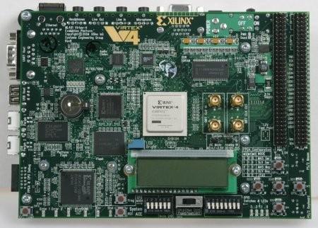
14 An FPGA

15 Logic Blocks
16 HOW TO PROGRAM FPGAs Configured using a Hardware Description Language Can be configured by any way by the user Basic Idea : BEHAVIOURAL DESCRIPTION OF REQUIRED CIRCUIT VERILOG SYNTHESISER A COMPLETE CIRCUIT DIAGRAM

17 Synthesis of VERILOG :
18 CODING IN VERILOG BREAKING CIRCUITS INTO VARIOUS BUILDING BLOCKS CALLED MODULE DEFINING MODULE CONNECTING VARIOUS MODULES
19 CODING IN VERILOG Communication between a module and its environment is achieved by using Ports Ports inout are of three types: input, output,
20 AN EXAMPLE : 4029 COUNTER Name: 4029 Input Ports: One Output Ports: Four Size Driver type Internal Logic: At every rising edge of the clock, increment the output by one
21 MODULE A Black Box in Verilog with inputs, outputs and internal logic working. So, a module can be used to implement a counter. A module is defined as module <specific type>(<port list>);
22 DEFINING 4029 MODULE Way 1: module 4029(clk,out,reset,enable); Way 2: module 4029(clk, a, b, c, d, reset, enable); Input and Output Ports in each of the above? EVERY Every PORT MUST HAVE A DIRECTION AND BITWIDTH module ends with the statement endmodule
23 DECLARING PORTS Way 1: input clk; input reset; input enable; output a,b,c,d; Way 2: input clk; input reset; input enable; output [3:0] out;
24 DRIVERS IN VERILOG We need drivers for this module in order to interact with the ports and describe its logical working. Two types of drivers: Can store a value (for example, flip-flop) : REG Cannot store a value, but connects two points (for example, a wire) : WIRE
25 DRIVERS IN 4029 Ports defined as wires? clk reset enable We do not need to stores the values of these ports in our logical block. Ports defined as reg? a,b,c,d out We need to store them so that we could modify their values when required.
26 DEFINING DRIVERS FOR 4029 Way 1: wire clk; wire reset; wire enable; reg a,b.c,d; Way 2: wire clk; wire reset; wire enable; reg [3:0] out;
27 Defining Internal Logic
28 OPERATORS AND CONDITIONAL OPERATORS All the arithmetic as well as logical operators in Verilog are similar to C, except ++ and -- which are not available in Verilog. Conditional statements are also similar to C with following modifications: { is replaced by begin. } is replaced by end.
29 COMBINATIONAL CIRCUITS Combinational circuits are acyclic interconnections of gates. And, Or, Not, Xor, Nand, Nor Multiplexers, Decoders, Encoders. OUTPUT IS A FUNCTION OF PRESENT INPUT ONLY
30 How are these gates, muxs etc. abstracted in Verilog? Gates, Add, Multiply : by simple operators like in C Multiplexers : by control statements like ifelse, case, etc Gate level implementation of above high level operators done by Verilog synthesizer.
31 SEQUENTIAL CIRCUITS Circuits containing state elements are called sequential circuits OUTPUT DEPENDS ON THE PRESENT INPUT AS WELL AS ON ITS PRESENT STATE. How do you implement such an element in Verilog?
32 always block Syntax begin //Code end Blocks starting with keyword always run symbol is used to specify the condition which should be satisfied for the execution of this block.
33 Usage of always block always The code in this block will keep on executing. The code in this block will be executed every time the value of a changes. clk) This block is executed at every positive edge of clk.
34 BLOCK It is an abstraction provided in Verilog to mainly implement sequential circuits. Also used for combinational circuits.
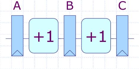
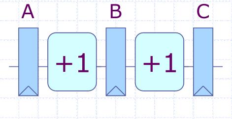
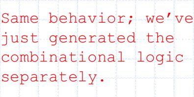
35 BLOCKING AND NON-BLOCKING ASSIGNMENTS Non-blocking assignments happen in parallel. ( #sensitivity list # ) begin B <= A ; C <= B ; (A,B) = (1,2) -> (B,C) = (1,2) end Blocking assignments happen sequentially. ( #sensitivity list # ) begin B =A; C=B; end (A,B) = (1,2) -> (B,C) = (1,1)
36 POINTS TO NOTE Use block with blocking assignments for combinational circuits Use posedge CLK) block with nonblocking assignments for sequential circuits. Do not mix blocking and non-blocking assignments.
37 A COMPLETE 4029 MODULE module 4029 ( input wire clk, input wire reset, input wire enable, output [3:0] reg out); //You can declare direction as well as data type //in the module definition.
38 clk) begin if (reset == 0 && enable == 0) begin out <= out +1; end end
39 or enable) begin if (reset == 1 b1) begin out <= 0; end end endmodule

40 AN EXAMPLE

41 ANOTHER EXAMPLE

42 WRONG SOLUTION
43 ANOTHER WAY : MULTIPLE always BLOCK


44 WRONG SOLUTION
45 Connecting Various Modules
46 Various modules are interconnected to make a larger circuit (or module). Each sub-module has a separate Verilog file. A sub-module may have another submodule in its circuit. One needs to indicate the top level module before synthesis.
47 EXAMPLE module 4029(input wire clk, output [3:0]reg out); module 7447(input [3:0] reg in, output [6:0] reg bcd); module TOP(input wire clk, output [6:0] reg bcd);
48 INSTANTIATION USED TO INTERCONNECT VARIOUS MODULES In the above example, we need to instantiate the two sub-modules in the top level module THIS IS DONE AS FOLLOWS: wire [3:0] c; 4029 counter (.clk(clk),.out(c) ); 7447 decoder (.in(c),.bcd(bcd));
49 Problem Statement Level 1 : Theoretical Questions on basic syntax of Verilog Level 2 : Design a digital system using Verilog. (weightage will be given to how much modular your circuit is )
FPGA Design Challenge :Techkriti 14 Digital Design using Verilog Part 1
 FPGA Design Challenge :Techkriti 14 Digital Design using Verilog Part 1 Anurag Dwivedi Digital Design : Bottom Up Approach Basic Block - Gates Digital Design : Bottom Up Approach Gates -> Flip Flops Digital
Nikhil Gupta. FPGA Challenge Takneek 2012
 Nikhil Gupta FPGA Challenge Takneek 2012 RECAP FPGA Field Programmable Gate Array Matrix of logic gates Can be configured in any way by the user Codes for FPGA are executed in parallel Configured using
Digital Design with FPGAs. By Neeraj Kulkarni
 Digital Design with FPGAs By Neeraj Kulkarni Some Basic Electronics Basic Elements: Gates: And, Or, Nor, Nand, Xor.. Memory elements: Flip Flops, Registers.. Techniques to design a circuit using basic
Verilog 1 - Fundamentals
 Verilog 1 - Fundamentals FA FA FA FA module adder( input [3:0] A, B, output cout, output [3:0] S ); wire c0, c1, c2; FA fa0( A[0], B[0], 1 b0, c0, S[0] ); FA fa1( A[1], B[1], c0, c1, S[1] ); FA fa2( A[2],
Digital Integrated Circuits
 Digital Integrated Circuits Lecture 4 Jaeyong Chung System-on-Chips (SoC) Laboratory Incheon National University BCD TO EXCESS-3 CODE CONVERTER 0100 0101 +0011 +0011 0111 1000 LSB received first Chung
ECE 2300 Digital Logic & Computer Organization. More Sequential Logic Verilog
 ECE 2300 Digital Logic & Computer Organization Spring 2018 More Sequential Logic Verilog Lecture 7: 1 Announcements HW3 will be posted tonight Prelim 1 Thursday March 1, in class Coverage: Lectures 1~7
EPC6055 Digital Integrated Circuits EXAM 1 Fall Semester 2013
 EPC6055 Digital Integrated Circuits EXAM 1 Fall Semester 2013 Print Here Student ID Signature This is a closed book exam. The exam is to be completed in one-hundred ten (110) minutes. Don t use scratch
Hardware Description Languages (HDLs) Verilog
 Verilog") Hardware Description Languages (HDLs) Verilog Material from Mano & Ciletti book By Kurtulus KULLU Ankara University What are HDLs? A Hardware Description Language resembles a programming language specifically
Hardware Description Languages (HDLs) Verilog Material from Mano & Ciletti book By Kurtulus KULLU Ankara University What are HDLs? A Hardware Description Language resembles a programming language specifically
N-input EX-NOR gate. N-output inverter. N-input NOR gate
 Hardware Description Language HDL Introduction HDL is a hardware description language used to design and document electronic systems. HDL allows designers to design at various levels of abstraction. It
Synthesis of Combinational and Sequential Circuits with Verilog
 Synthesis of Combinational and Sequential Circuits with Verilog What is Verilog? Hardware description language: Are used to describe digital system in text form Used for modeling, simulation, design Two
Chap 6 Introduction to HDL (d)
") Design with Verilog Chap 6 Introduction to HDL (d) Credit to: MD Rizal Othman Faculty of Electrical & Electronics Engineering Universiti Malaysia Pahang Ext: 6036 VERILOG HDL Basic Unit A module Module
Design with Verilog Chap 6 Introduction to HDL (d) Credit to: MD Rizal Othman Faculty of Electrical & Electronics Engineering Universiti Malaysia Pahang Ext: 6036 VERILOG HDL Basic Unit A module Module
The Verilog Language COMS W Prof. Stephen A. Edwards Fall 2002 Columbia University Department of Computer Science
 The Verilog Language COMS W4995-02 Prof. Stephen A. Edwards Fall 2002 Columbia University Department of Computer Science The Verilog Language Originally a modeling language for a very efficient event-driven
Register Transfer Level in Verilog: Part I
 Source: M. Morris Mano and Michael D. Ciletti, Digital Design, 4rd Edition, 2007, Prentice Hall. Register Transfer Level in Verilog: Part I Lan-Da Van ( 范倫達 ), Ph. D. Department of Computer Science National
Verilog introduction. Embedded and Ambient Systems Lab
 Verilog introduction Embedded and Ambient Systems Lab Purpose of HDL languages Modeling hardware behavior Large part of these languages can only be used for simulation, not for hardware generation (synthesis)
Verilog. What is Verilog? VHDL vs. Verilog. Hardware description language: Two major languages. Many EDA tools support HDL-based design
 Verilog What is Verilog? Hardware description language: Are used to describe digital system in text form Used for modeling, simulation, design Two major languages Verilog (IEEE 1364), latest version is
Design Using Verilog
 EGC220 Design Using Verilog Baback Izadi Division of Engineering Programs bai@engr.newpaltz.edu Basic Verilog Lexical Convention Lexical convention are close to C++. Comment // to the of the line. /* to
Hardware Description Language VHDL (1) Introduction
 Introduction") Hardware Description Language VHDL (1) Introduction Digital Radiation Measurement and Spectroscopy NE/RHP 537 Introduction Hardware description language (HDL) Intended to describe circuits textually, for
Hardware Description Language VHDL (1) Introduction Digital Radiation Measurement and Spectroscopy NE/RHP 537 Introduction Hardware description language (HDL) Intended to describe circuits textually, for
Computer Aided Design Basic Syntax Gate Level Modeling Behavioral Modeling. Verilog
 Verilog Radek Pelánek and Šimon Řeřucha Contents 1 Computer Aided Design 2 Basic Syntax 3 Gate Level Modeling 4 Behavioral Modeling Computer Aided Design Hardware Description Languages (HDL) Verilog C
structure syntax different levels of abstraction
 This and the next lectures are about Verilog HDL, which, together with another language VHDL, are the most popular hardware languages used in industry. Verilog is only a tool; this course is about digital
Here is a list of lecture objectives. They are provided for you to reflect on what you are supposed to learn, rather than an introduction to this
 This and the next lectures are about Verilog HDL, which, together with another language VHDL, are the most popular hardware languages used in industry. Verilog is only a tool; this course is about digital
Digital Circuit Design and Language. Datapath Design. Chang, Ik Joon Kyunghee University
 Digital Circuit Design and Language Datapath Design Chang, Ik Joon Kyunghee University Typical Synchronous Design + Control Section : Finite State Machine + Data Section: Adder, Multiplier, Shift Register
register:a group of binary cells suitable for holding binary information flip-flops + gates
 9 차시 1 Ch. 6 Registers and Counters 6.1 Registers register:a group of binary cells suitable for holding binary information flip-flops + gates control when and how new information is transferred into the
ENEE245 Digital Circuits and Systems Lab Manual
 ENEE245 Digital Circuits and Systems Lab Manual Department of Engineering, Physical & Computer Sciences Montgomery College Version 1.1 Copyright Prof. Lan Xiang (Do not distribute without permission) 1
Verilog Hardware Description Language ROOM: B405
 Verilog Hardware Description Language HONG@IS.NAIST.JP ROOM: B405 Content Lecture 1: Computer organization and performance evaluation metrics Lecture 2: Processor architecture and memory system Lecture
This Lecture. Some components (useful for the homework) Verilog HDL (will continue next lecture)
 Verilog HDL (will continue next lecture)") Last Lecture The basic component of a digital circuit is the MOS transistor Transistor have instrinsic resistance and capacitance, so voltage values in the circuit take some time to change ( delay ) There
Last Lecture The basic component of a digital circuit is the MOS transistor Transistor have instrinsic resistance and capacitance, so voltage values in the circuit take some time to change ( delay ) There
ENEE245 Digital Circuits and Systems Lab Manual
 ENEE245 Digital Circuits and Systems Lab Manual Department of Engineering, Physical & Computer Sciences Montgomery College Modified Fall 2017 Copyright Prof. Lan Xiang (Do not distribute without permission)
Why Should I Learn This Language? VLSI HDL. Verilog-2
 Verilog Why Should I Learn This Language? VLSI HDL Verilog-2 Different Levels of Abstraction Algorithmic the function of the system RTL the data flow the control signals the storage element and clock Gate
EECS150 - Digital Design Lecture 5 - Verilog Logic Synthesis
 EECS150 - Digital Design Lecture 5 - Verilog Logic Synthesis Jan 31, 2012 John Wawrzynek Spring 2012 EECS150 - Lec05-verilog_synth Page 1 Outline Quick review of essentials of state elements Finite State
Outline. EECS Components and Design Techniques for Digital Systems. Lec 11 Putting it all together Where are we now?
 Outline EECS 5 - Components and Design Techniques for Digital Systems Lec Putting it all together -5-4 David Culler Electrical Engineering and Computer Sciences University of California Berkeley Top-to-bottom
CAD for VLSI Design - I. Lecture 21 V. Kamakoti and Shankar Balachandran
 CAD for VLSI Design - I Lecture 21 V. Kamakoti and Shankar Balachandran Overview of this Lecture Understanding the process of Logic synthesis Logic Synthesis of HDL constructs Logic Synthesis What is this?
Lecture #2: Verilog HDL
 Lecture #2: Verilog HDL Paul Hartke Phartke@stanford.edu Stanford EE183 April 8, 2002 EE183 Design Process Understand problem and generate block diagram of solution Code block diagram in verilog HDL Synthesize
ECE 551: Digital System *
 ECE 551: Digital System * Design & Synthesis Lecture Set 5 5.1: Verilog Behavioral Model for Finite State Machines (FSMs) 5.2: Verilog Simulation I/O and 2001 Standard (In Separate File) 3/4/2003 1 Explicit
CSE140L: Components and Design Techniques for Digital Systems Lab
 CSE140L: Components and Design Techniques for Digital Systems Lab Tajana Simunic Rosing Source: Vahid, Katz, Culler 1 Announcements & Outline Lab 4 due; demo signup times listed on the cse140l site Check
FPGA Design Challenge Techkriti Digital Logic Design using Verilog Part 2 By Neeraj Kulkarni
 FPGA Design Challenge Techkriti 2013 Digital Logic Design using Verilog Part 2 By Neeraj Kulkarni Recap Verilog- Hardware Description Language Modules Combinational circuits assign statement Control statements
Synthesizable Verilog
 Synthesizable Verilog Courtesy of Dr. Edwards@Columbia, and Dr. Franzon@NCSU http://csce.uark.edu +1 (479) 575-6043 yrpeng@uark.edu Design Methodology Structure and Function (Behavior) of a Design HDL
Verilog for Synthesis Ing. Pullini Antonio
 Verilog for Synthesis Ing. Pullini Antonio antonio.pullini@epfl.ch Outline Introduction to Verilog HDL Describing combinational logic Inference of basic combinational blocks Describing sequential circuits
Brief Introduction to Verilog HDL (Part 1)
") BUDAPEST UNIVERSITY OF TECHNOLOGY AND ECONOMICS FACULTY OF ELECTRICAL ENGINEERING AND INFORMATICS DEPARTMENT OF MEASUREMENT AND INFORMATION SYSTEMS Brief Introduction to Verilog HDL (Part 1) Tamás Raikovich
BUDAPEST UNIVERSITY OF TECHNOLOGY AND ECONOMICS FACULTY OF ELECTRICAL ENGINEERING AND INFORMATICS DEPARTMENT OF MEASUREMENT AND INFORMATION SYSTEMS Brief Introduction to Verilog HDL (Part 1) Tamás Raikovich
Topics. Midterm Finish Chapter 7
 Lecture 9 Topics Midterm Finish Chapter 7 ROM (review) Memory device in which permanent binary information is stored. Example: 32 x 8 ROM Five input lines (2 5 = 32) 32 outputs, each representing a memory
ECE 4514 Digital Design II. Spring Lecture 7: Dataflow Modeling
 ECE 4514 Digital Design II Lecture 7: Dataflow Modeling A language Lecture Today's topic Dataflow Modeling input input input module output output Model with submodules and gates = Structural Model with
FPGA: FIELD PROGRAMMABLE GATE ARRAY Verilog: a hardware description language. Reference: [1]
![FPGA: FIELD PROGRAMMABLE GATE ARRAY Verilog: a hardware description language. Reference: [1]](/thumbs/80/81661285.jpg "FPGA: FIELD PROGRAMMABLE GATE ARRAY Verilog: a hardware description language. Reference: [1]") FPGA: FIELD PROGRAMMABLE GATE ARRAY Verilog: a hardware description language Reference: [] FIELD PROGRAMMABLE GATE ARRAY FPGA is a hardware logic device that is programmable Logic functions may be programmed
FPGA: FIELD PROGRAMMABLE GATE ARRAY Verilog: a hardware description language Reference: [] FIELD PROGRAMMABLE GATE ARRAY FPGA is a hardware logic device that is programmable Logic functions may be programmed
CSE140L: Components and Design
 CSE140L: Components and Design Techniques for Digital Systems Lab Tajana Simunic Rosing Source: Vahid, Katz, Culler 1 Grade distribution: 70% Labs 35% Lab 4 30% Lab 3 20% Lab 2 15% Lab 1 30% Final exam
Verilog Tutorial (Structure, Test)
") Digital Circuit Design and Language Verilog Tutorial (Structure, Test) Chang, Ik Joon Kyunghee University Hierarchical Design Top-down Design Methodology Bottom-up Design Methodology Module START Example)
Digital Circuit Design and Language Verilog Tutorial (Structure, Test) Chang, Ik Joon Kyunghee University Hierarchical Design Top-down Design Methodology Bottom-up Design Methodology Module START Example)
Verilog Module 1 Introduction and Combinational Logic
 Verilog Module 1 Introduction and Combinational Logic Jim Duckworth ECE Department, WPI 1 Module 1 Verilog background 1983: Gateway Design Automation released Verilog HDL Verilog and simulator 1985: Verilog
Chapter 2 Using Hardware Description Language Verilog. Overview
 Chapter 2 Using Hardware Description Language Verilog CSE4210 Winter 2012 Mokhtar Aboelaze based on slides by Dr. Shoab A. Khan Overview Algorithm development isa usually done in MATLAB, C, or C++ Code
Online Verilog Resources
 EECS 427 Discussion 6: Verilog HDL Reading: Many references EECS 427 F08 Discussion 6 1 Online Verilog Resources ASICs the book, Ch. 11: http://www.ge.infn.it/~pratolo/verilog/verilogtutorial.pdf it/ pratolo/verilog/verilogtutorial
Lecture 15: System Modeling and Verilog
 Lecture 15: System Modeling and Verilog Slides courtesy of Deming Chen Intro. VLSI System Design Outline Outline Modeling Digital Systems Introduction to Verilog HDL Use of Verilog HDL in Synthesis Reading
Verilog 1 - Fundamentals
 Verilog 1 - Fundamentals FA FA FA FA module adder( input [3:0] A, B, output cout, output [3:0] S ); wire c0, c1, c2; FA fa0( A[0], B[0], 1 b0, c0, S[0] ); FA fa1( A[1], B[1], c0, c1, S[1] ); FA fa2( A[2],
Abi Farsoni, Department of Nuclear Engineering and Radiation Health Physics, Oregon State University
 Hardware description language (HDL) Intended to describe circuits textually, for a computer to read Evolved starting in the 1970s and 1980s Popular languages today include: VHDL Defined in 1980s by U.S.
PINE TRAINING ACADEMY
 PINE TRAINING ACADEMY Course Module A d d r e s s D - 5 5 7, G o v i n d p u r a m, G h a z i a b a d, U. P., 2 0 1 0 1 3, I n d i a Digital Logic System Design using Gates/Verilog or VHDL and Implementation
Two hours - online EXAM PAPER MUST NOT BE REMOVED FROM THE EXAM ROOM UNIVERSITY OF MANCHESTER SCHOOL OF COMPUTER SCIENCE
 COMP 12111 Two hours - online This paper version is made available as a backup In this event, only MCQ answers written in the boxes on the exam paper will be marked. EXAM PAPER MUST NOT BE REMOVED FROM
Date Performed: Marks Obtained: /10. Group Members (ID):. Experiment # 11. Introduction to Verilog II Sequential Circuits
:. Experiment # 11. Introduction to Verilog II Sequential Circuits") Name: Instructor: Engr. Date Performed: Marks Obtained: /10 Group Members (ID):. Checked By: Date: Experiment # 11 Introduction to Verilog II Sequential Circuits OBJECTIVES: To understand the concepts
Name: Instructor: Engr. Date Performed: Marks Obtained: /10 Group Members (ID):. Checked By: Date: Experiment # 11 Introduction to Verilog II Sequential Circuits OBJECTIVES: To understand the concepts
Advanced Digital Design Using FPGA. Dr. Shahrokh Abadi
 Advanced Digital Design Using FPGA Dr. Shahrokh Abadi 1 Venue Computer Lab: Tuesdays 10 12 am (Fixed) Computer Lab: Wednesday 10-12 am (Every other odd weeks) Note: Due to some unpredicted problems with
Graphics: Alexandra Nolte, Gesine Marwedel, Universität Dortmund. RTL Synthesis
 Graphics: Alexandra Nolte, Gesine Marwedel, 2003 Universität Dortmund RTL Synthesis Purpose of HDLs Purpose of Hardware Description Languages: Capture design in Register Transfer Language form i.e. All
Verilog for High Performance
 Verilog for High Performance Course Description This course provides all necessary theoretical and practical know-how to write synthesizable HDL code through Verilog standard language. The course goes
Workshop on Digital Circuit Design in FPGA
 Organized by: Dept. of EEE Workshop on Digital Circuit Design in FPGA Presented By Mohammed Abdul Kader Assistant Professor, Dept. of EEE, IIUC Email:kader05cuet@gmail.com Website: kader05cuet.wordpress.com
Spiral 1 / Unit 4 Verilog HDL. Digital Circuit Design Steps. Digital Circuit Design OVERVIEW. Mark Redekopp. Description. Verification.
 1-4.1 1-4.2 Spiral 1 / Unit 4 Verilog HDL Mark Redekopp OVERVIEW 1-4.3 1-4.4 Digital Circuit Design Steps Digital Circuit Design Description Design and computer-entry of circuit Verification Input Stimulus
Speaker: Shao-Wei Feng Adviser: Prof. An-Yeu Wu Date: 2010/09/28
 99-1 Under-Graduate Project Verilog Simulation & Debugging Tools Speaker: Shao-Wei Feng Adviser: Prof. An-Yeu Wu Date: 2010/09/28 ACCESS IC LAB Outline Basic Concept of Verilog HDL Gate Level Modeling
Introduction to Verilog HDL. Verilog 1
 Introduction to HDL Hardware Description Language (HDL) High-Level Programming Language Special constructs to model microelectronic circuits Describe the operation of a circuit at various levels of abstraction
Contents. Appendix D Verilog Summary Page 1 of 16
 Appix D Verilog Summary Page 1 of 16 Contents Appix D Verilog Summary... 2 D.1 Basic Language Elements... 2 D.1.1 Keywords... 2 D.1.2 Comments... 2 D.1.3 Identifiers... 2 D.1.4 Numbers and Strings... 3
 UNIT II - COMBINATIONAL LOGIC Part A 2 Marks. 1. Define Combinational circuit A combinational circuit consist of logic gates whose outputs at anytime are determined directly from the present combination
ECE 574: Modeling and Synthesis of Digital Systems using Verilog and VHDL. Fall 2017 Final Exam (6.00 to 8.30pm) Verilog SOLUTIONS
 Verilog SOLUTIONS") ECE 574: Modeling and Synthesis of Digital Systems using Verilog and VHDL Fall 2017 Final Exam (6.00 to 8.30pm) Verilog SOLUTIONS Note: Closed book no notes or other material allowed apart from the one
ECE 574: Modeling and Synthesis of Digital Systems using Verilog and VHDL Fall 2017 Final Exam (6.00 to 8.30pm) Verilog SOLUTIONS Note: Closed book no notes or other material allowed apart from the one
CSCB58 - Lab 3. Prelab /3 Part I (in-lab) /2 Part II (in-lab) /2 TOTAL /8
 /2 Part II (in-lab) /2 TOTAL /8") CSCB58 - Lab 3 Latches, Flip-flops, and Registers Learning Objectives The purpose of this exercise is to investigate the fundamental synchronous logic elements: latches, flip-flops, and registers. Prelab
CSCB58 - Lab 3 Latches, Flip-flops, and Registers Learning Objectives The purpose of this exercise is to investigate the fundamental synchronous logic elements: latches, flip-flops, and registers. Prelab
ECEN 468 Advanced Logic Design
 ECEN 468 Advanced Logic Design Lecture 28: Synthesis of Language Constructs Synthesis of Nets v An explicitly declared net may be eliminated in synthesis v Primary input and output (ports) are always retained
Combinational Logic II
 Combinational Logic II Ranga Rodrigo July 26, 2009 1 Binary Adder-Subtractor Digital computers perform variety of information processing tasks. Among the functions encountered are the various arithmetic
RTL Design (Using ASM/SM Chart)
") Digital Circuit Design and Language RTL Design (Using ASM/SM Chart) Chang, Ik Joon Kyunghee University Process of Logic Simulation and Synthesis Design Entry HDL Description Logic Simulation Functional
Digital Circuit Design and Language RTL Design (Using ASM/SM Chart) Chang, Ik Joon Kyunghee University Process of Logic Simulation and Synthesis Design Entry HDL Description Logic Simulation Functional
Verilog Tutorial. Introduction. T. A.: Hsueh-Yi Lin. 2008/3/12 VLSI Digital Signal Processing 2
 Verilog Tutorial T. A.: Hsueh-Yi Lin Introduction 2008/3/12 VLSI Digital Signal Processing 2 Verilog: A common language for industry HDL is a common way for hardware design Verilog VHDL Verilog is widely
VERILOG. Deepjyoti Borah, Diwahar Jawahar
 VERILOG Deepjyoti Borah, Diwahar Jawahar Outline 1. Motivation 2. Basic Syntax 3. Sequential and Parallel Blocks 4. Conditions and Loops in Verilog 5. Procedural Assignment 6. Timing controls 7. Combinatorial
CS429: Computer Organization and Architecture
 CS429: Computer Organization and Architecture Dr. Bill Young Department of Computer Sciences University of Texas at Austin Last updated: January 2, 2018 at 11:23 CS429 Slideset 5: 1 Topics of this Slideset
Introduction to Verilog/System Verilog
 NTUEE DCLAB Feb. 27, 2018 Introduction to Verilog/System Verilog Presenter: Yao-Pin Wang 王耀斌 Advisor: Prof. Chia-Hsiang Yang 楊家驤 Dept. of Electrical Engineering, NTU National Taiwan University What is
a, b sum module add32 sum vector bus sum[31:0] sum[0] sum[31]. sum[7:0] sum sum overflow module add32_carry assign
![a, b sum module add32 sum vector bus sum[31:0] sum[0] sum[31]. sum[7:0] sum sum overflow module add32_carry assign](/thumbs/91/106466219.jpg "a, b sum module add32 sum vector bus sum[31:0] sum[0] sum[31]. sum[7:0] sum sum overflow module add32_carry assign") I hope you have completed Part 1 of the Experiment. This lecture leads you to Part 2 of the experiment and hopefully helps you with your progress to Part 2. It covers a number of topics: 1. How do we specify
I hope you have completed Part 1 of the Experiment. This lecture leads you to Part 2 of the experiment and hopefully helps you with your progress to Part 2. It covers a number of topics: 1. How do we specify
Digital Design with SystemVerilog
 Digital Design with SystemVerilog Prof. Stephen A. Edwards Columbia University Spring 25 Synchronous Digital Design Combinational Logic Sequential Logic Summary of Modeling Styles Testbenches Why HDLs?
EEL 4783: HDL in Digital System Design
 EEL 4783: HDL in Digital System Design Lecture 15: Logic Synthesis with Verilog Prof. Mingjie Lin 1 Verilog Synthesis Synthesis vs. Compilation Descriptions mapped to hardware Verilog design patterns for
EECS150 - Digital Design Lecture 10 Logic Synthesis
 EECS150 - Digital Design Lecture 10 Logic Synthesis September 26, 2002 John Wawrzynek Fall 2002 EECS150 Lec10-synthesis Page 1 Logic Synthesis Verilog and VHDL stated out as simulation languages, but quickly
CSE140L: Components and Design Techniques for Digital Systems Lab. Verilog HDL. Instructor: Mohsen Imani UC San Diego. Source: Eric Crabill, Xilinx
 CSE140L: Components and Design Techniques for Digital Systems Lab Verilog HDL Instructor: Mohsen Imani UC San Diego Source: Eric Crabill, Xilinx 1 Hardware description languages Used to describe & model
EECS150 - Digital Design Lecture 4 - Verilog Introduction. Outline
 EECS150 - Digital Design Lecture 4 - Verilog Introduction Feb 3, 2009 John Wawrzynek Spring 2009 EECS150 - Lec05-Verilog Page 1 Outline Background and History of Hardware Description Brief Introduction
HDLs and SystemVerilog. Digital Computer Design
 HDLs and SystemVerilog Digital Computer Design Logic Arrays Gates can be organized into regular arrays. If the connections are made programmable, these logic arrays can be configured to perform any function
Speaker: Kayting Adviser: Prof. An-Yeu Wu Date: 2009/11/23
 98-1 Under-Graduate Project Synthesis of Combinational Logic Speaker: Kayting Adviser: Prof. An-Yeu Wu Date: 2009/11/23 What is synthesis? Outline Behavior Description for Synthesis Write Efficient HDL
Lecture 32: SystemVerilog
 Lecture 32: SystemVerilog Outline SystemVerilog module adder(input logic [31:0] a, input logic [31:0] b, output logic [31:0] y); assign y = a + b; Note that the inputs and outputs are 32-bit busses. 17:
Verilog HDL. Gate-Level Modeling
 Verilog HDL Verilog is a concurrent programming language unlike C, which is sequential in nature. block - executes once at time 0. If there is more then one block, each execute concurrently always block
Verilog. Verilog for Synthesis
 Verilog Verilog for Synthesis 1 Verilog background 1983: Gateway Design Automation released Verilog HDL Verilog and simulator 1985: Verilog enhanced version Verilog-XL 1987: Verilog-XL becoming more popular
Synthesis vs. Compilation Descriptions mapped to hardware Verilog design patterns for best synthesis. Spring 2007 Lec #8 -- HW Synthesis 1
 Verilog Synthesis Synthesis vs. Compilation Descriptions mapped to hardware Verilog design patterns for best synthesis Spring 2007 Lec #8 -- HW Synthesis 1 Logic Synthesis Verilog and VHDL started out
Writing Circuit Descriptions 8
 8 Writing Circuit Descriptions 8 You can write many logically equivalent descriptions in Verilog to describe a circuit design. However, some descriptions are more efficient than others in terms of the
In this lecture, we will go beyond the basic Verilog syntax and examine how flipflops and other clocked circuits are specified.
 1 In this lecture, we will go beyond the basic Verilog syntax and examine how flipflops and other clocked circuits are specified. I will also introduce the idea of a testbench as part of a design specification.
MODELING LANGUAGES AND ABSTRACT MODELS. Giovanni De Micheli Stanford University. Chapter 3 in book, please read it.
 MODELING LANGUAGES AND ABSTRACT MODELS Giovanni De Micheli Stanford University Chapter 3 in book, please read it. Outline Hardware modeling issues: Representations and models. Issues in hardware languages.
Digital Design (VIMIAA01) Introduction to the Verilog HDL
 Introduction to the Verilog HDL") BUDAPEST UNIVERSITY OF TECHNOLOGY AND ECONOMICS FACULTY OF ELECTRICAL ENGINEERING AND INFORMATICS DEPARTMENT OF MEASUREMENT AND INFORMATION SYSTEMS Digital Design (VIMIAA01) Introduction to the Verilog
BUDAPEST UNIVERSITY OF TECHNOLOGY AND ECONOMICS FACULTY OF ELECTRICAL ENGINEERING AND INFORMATICS DEPARTMENT OF MEASUREMENT AND INFORMATION SYSTEMS Digital Design (VIMIAA01) Introduction to the Verilog
EECS150 - Digital Design Lecture 8 - Hardware Description Languages
 EECS150 - Digital Design Lecture 8 - Hardware Description Languages September 19, 2002 John Wawrzynek Fall 2002 EECS150 - Lec08-HDL Page 1 Netlists Design flow What is a HDL? Verilog history examples Outline
VHDL VS VERILOG.
 1 VHDL VS VERILOG http://www.cse.cuhk.edu.hk/~mcyang/teaching.html 2 VHDL & Verilog They are both hardware description languages for modeling hardware. They are each a notation to describe the behavioral
Verilog HDL. Testing & Verification Dept. of Computer Science & Engg,, IIT Kharagpur
 Verilog HDL Testing & Verification Dept. of Computer Science & Engg,, IIT Kharagpur Pallab Dasgupta Professor, Dept. of Computer Science & Engg., Professor-in in-charge, AVLSI Design Lab, Indian Institute
Synthesis of Language Constructs. 5/10/04 & 5/13/04 Hardware Description Languages and Synthesis
 Synthesis of Language Constructs 1 Nets Nets declared to be input or output ports are retained Internal nets may be eliminated due to logic optimization User may force a net to exist trireg, tri0, tri1
EE 231 Fall EE 231 Homework 8 Due October 20, 2010
 EE 231 Homework 8 Due October 20, 20 1. Consider the circuit below. It has three inputs (x and clock), and one output (z). At reset, the circuit starts with the outputs of all flip-flops at 0. x z J Q
Module 4. Design of Embedded Processors. Version 2 EE IIT, Kharagpur 1
 Module 4 Design of Embedded Processors Version 2 EE IIT, Kharagpur 1 Lesson 23 Introduction to Hardware Description Languages-III Version 2 EE IIT, Kharagpur 2 Instructional Objectives At the end of the
Chapter 4 :: Topics. Introduction. SystemVerilog. Hardware description language (HDL): allows designer to specify logic function only.
: allows designer to specify logic function only.") Chapter 4 :: Hardware Description Languages Digital Design and Computer Architecture David Money Harris and Sarah L. Harris Chapter 4 :: Topics Introduction Combinational Logic Structural Modeling Sequential
Chapter 4 :: Hardware Description Languages Digital Design and Computer Architecture David Money Harris and Sarah L. Harris Chapter 4 :: Topics Introduction Combinational Logic Structural Modeling Sequential
(ii) Simplify and implement the following SOP function using NOR gates:
 Simplify and implement the following SOP function using NOR gates:") DHANALAKSHMI COLLEGE OF ENGINEERING DEPARTMENT OF ELECTRONICS AND COMMUNICATION ENGINEERING EE6301 DIGITAL LOGIC CIRCUITS UNIT I NUMBER SYSTEMS AND DIGITAL LOGIC FAMILIES PART A 1. How can an OR gate be
DHANALAKSHMI COLLEGE OF ENGINEERING DEPARTMENT OF ELECTRONICS AND COMMUNICATION ENGINEERING EE6301 DIGITAL LOGIC CIRCUITS UNIT I NUMBER SYSTEMS AND DIGITAL LOGIC FAMILIES PART A 1. How can an OR gate be
L3: Introduction to Verilog (Combinational Logic)
") L3: Introduction to Verilog (Combinational Logic) Courtesy of Rex in. Used with permission. Verilog References: Samir Palnitkar, Verilog HDL, Pearson Education (2nd edition). Donald Thomas, Philip oorby,
L3: Introduction to Verilog (Combinational Logic) Courtesy of Rex in. Used with permission. Verilog References: Samir Palnitkar, Verilog HDL, Pearson Education (2nd edition). Donald Thomas, Philip oorby,
Schematic design. Gate level design. 0 EDA (Electronic Design Assistance) 0 Classical design. 0 Computer based language
 0 Classical design. 0 Computer based language") 1 / 15 2014/11/20 0 EDA (Electronic Design Assistance) 0 Computer based language 0 HDL (Hardware Description Language) 0 Verilog HDL 0 Created by Gateway Design Automation Corp. in 1983 First modern hardware
1 / 15 2014/11/20 0 EDA (Electronic Design Assistance) 0 Computer based language 0 HDL (Hardware Description Language) 0 Verilog HDL 0 Created by Gateway Design Automation Corp. in 1983 First modern hardware
C-Based Hardware Design
 LECTURE 6 In this lecture we will introduce: The VHDL Language and its benefits. The VHDL entity Concurrent and Sequential constructs Structural design. Hierarchy Packages Various architectures Examples
Graduate Institute of Electronics Engineering, NTU. Lecturer: Chihhao Chao Date:
 Synthesizable Coding of Verilog Lecturer: Date: 2009.03.18 ACCESS IC LAB Outline Basic concepts of logic synthesis Synthesizable Verilog coding subset Verilog coding practices Coding for readability Coding
Readings: Storage unit. Can hold an n-bit value Composed of a group of n flip-flops. Each flip-flop stores 1 bit of information.
 Registers Readings: 5.8-5.9.3 Storage unit. Can hold an n-bit value Composed of a group of n flip-flops Each flip-flop stores 1 bit of information ff ff ff ff 178 Controlled Register Reset Load Action
Digital Integrated Circuits
 Digital Integrated Circuits Lecture 3 Jaeyong Chung System-on-Chips (SoC) Laboratory Incheon National University GENERAL MODEL OF MEALY MACHINE Chung EPC6055 2 GENERAL MODEL OF MOORE MACHINE Chung EPC6055
EECS150 - Digital Design Lecture 10 Logic Synthesis
 EECS150 - Digital Design Lecture 10 Logic Synthesis February 13, 2003 John Wawrzynek Spring 2003 EECS150 Lec8-synthesis Page 1 Logic Synthesis Verilog and VHDL started out as simulation languages, but