Short Course On Phase-Locked Loops and Their Applications Day 3, PM Lecture. Behavioral Simulation Exercises
|
|
|
- Jeffry Wright
- 6 years ago
- Views:
Transcription
1 Short Course On Phase-Locked Loops and Their Applications Day 3, PM Lecture Behavioral Simulation Exercises Michael H Perrott August 13, 2008 Copyright 2008 by Michael H. Perrott All rights reserved.

2 A Modern Analog Custom IC A 2.5 Gb/s CDR for high speed links - Analog amplification and phase sensing - Digital filtering and calibration - RF clock generation (2.5 GHz) How do we design such chips? 2
3 Simplified View of a Top Down, Mixed-Signal Design Flow System Design Architecture High Level Investigation & Analysis Schematic Creation Circuit Design Analog Circuit Design Digital Creation Place & Route Extracted Layout Creation PVT Corners Monte Carlo Circuit Verification Analog Circuit Verification Digital Digital Test Vectors Timing Checks System Verification Circ. & Arch. System Level Test Vectors 3
4 The Many Simulation Tools Involved Popular Tools System Design Architecture Matlab/Simulink ADS Circuit Design Analog Circuit Design Digital SPICE Verilog/VHDL Circuit Verification Analog Circuit Verification Digital Verilog AMS AMS Designer System Verification Circ. & Arch.???????? 4
5 Goal: Create a Universal Simulator System Designer Analog Designer Digital Designer Managing Kernel SPICE Matlab Verilog VHDL The challenges of developing the Managing Kernel - Difficult to match up simulator signals at their boundaries without overly complicating the life of the user - Difficult to maintain fast simulation speed - Difficult to retrain designers on a new tool with a new flow 5
6 A Different Approach Look for commonality among simulators to allow universal simulation models to be used - C++ provides one such hook Allow designers to use their tool of choice while sharing universal simulation models SPICE Matlab Verilog VHDL C/C++ PLI Calls (Verilog AMS & AMS Designer) C/C++ Mex functions C/C++ PLI Calls Key idea: bootstrap into existing simulators 6
7 The VppSim Simulator Greatly Simplifies This Process Cadence Schematic Entry C++ primitive library Simulation parameter file Graphically driven generation of simulator blocks based on a C++ primitive library Automatic wrapper generation Verilog PLI Calls Verilog PLI Mex & Gen. Function AMS Designer Matlab NCVerilog Analog Designer System Designer Digital Designer 7
8 C++ Can Also Be Directly Simulated Cadence Schematic Entry C++ primitive library Simulation parameter file Automatic C++ system generation Automatic wrapper generation CppSim Advantage: - Very fast! Verilog PLI Calls Verilog PLI Mex & Gen. Function AMS Designer Matlab NCVerilog Analog Designer System Designer Digital Designer 8
9 CppSim Compiler Simulation File Time step value Number of sim steps Probing of signals C++ Simulation Program SPICE Netlist Topology of system - Generated by Cadence or Sue2 9
10 VppSim Compiler (for NCVerilog) Verilog Wrapper for Module Verilog PLI function calls Embedded C++ Class Object Simulation File Time step value Number of sim steps Probing of signals Verilog Wrapper for Module Verilog PLI function calls Embedded C++ Class Object Native Verilog Modules ASCII file descriptions Verilog Simulation Program Verilog Wrapper for Module Verilog PLI function calls Embedded C++ Class Object SPICE Netlist Topology of system - Generated by Cadence All CppSim modules supported (including vector signals) Same timing approach for module execution as CppSim 10
11 VppSim Modules for AMS Verilog Wrapper for Module Verilog PLI function calls Embedded C++ Class Object Verilog Wrapper for Module Verilog PLI function calls Embedded C++ Class Object AMS Simulation Program Verilog Wrapper for Module Verilog PLI function calls Embedded C++ Class Object Not all CppSim modules are supported (i.e., no vector signals) Different timing approach for module execution 11
12 Example with Double Signals CppSim module module: leadlagfilter parameters: double fz, double fp, double gain inputs: double in outputs: double out static_variables: classes: Filter filt("1+1/(2*pi*fz)s", "C3*s + C3/(2*pi*fp)*s^2", "C3,fz,fp,Ts",1/gain,fz,fp,Ts); init: code: filt.inp(in); out = filt.out; ////// Auto-generated from CppSim module ////// module leadlagfilter(in, out); parameter fz = e+00; parameter fp = e+00; parameter gain = e+00; input in; output out; wreal in; real in_rv; wreal out; real out_rv; VppSim module assign out = out_rv; initial begin assign in_rv = in; end always begin #1 $leadlagfilter_cpp(in_rv,out_rv,fz,fp,gain); end endmodule 12
13 The Issue of Timing/Ordering (1) Best Execution Order Execution Order A B C A E B C D E Delay D (2) Impact of Alternate Ordering Arrangement Execution Order A B Delay C A E C B D E Delay D Ordering influences delays CppSim blocks are ordered automatically or by user 13

14 Cadence Interface Choose between CppSim, VppSim (for NCVerilog), and AMS with VppSim modules CppSim and VppSim run in above window or in Matlab 14
15 Windows Version of CppSim Will be used in class today Available for free download at Initial part of this session: fractional-n example Remaining part of this session: example of your choice 15

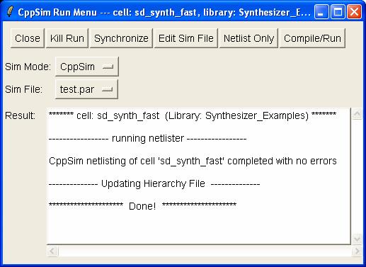
16 Windows Interface 16
Fast and Accurate System Level Simulation of Time-Based Circuits Using CppSim and VppSim
 Fast and Accurate System Level Simulation of Time-Based Circuits Using CppSim and VppSim Michael H. Perrott March 12, 2016 Copyright 2016 by Michael H. Perrott All rights reserved. Modern Mixed Signal
VCS AMS. Mixed-Signal Verification Solution. Overview. testing with transistor-level accuracy. Introduction. Performance. Multicore Technology
 DATASHEET VCS AMS Mixed-Signal Verification Solution Scalable mixedsignal regression testing with transistor-level accuracy Overview The complexity of mixed-signal system-on-chip (SoC) designs is rapidly
Harmony-AMS Analog/Mixed-Signal Simulator
 Harmony-AMS Analog/Mixed-Signal Simulator Yokohama, June 2004 Workshop 7/15/04 Challenges for a True Single-Kernel A/MS Simulator Accurate partition of analog and digital circuit blocks Simple communication
Connecting MATLAB & Simulink with your SystemVerilog Workflow for Functional Verification
 Connecting MATLAB & Simulink with your SystemVerilog Workflow for Functional Verification Corey Mathis Industry Marketing Manager Communications, Electronics, and Semiconductors MathWorks 2014 MathWorks,
THE DESIGNER'S GUIDE TO VERILOG-AMS First Edition June 2004
 THE DESIGNER'S GUIDE TO VERILOG-AMS First Edition June 2004 KENNETH S. KUNDERT Cadence Design Systems OLAF ZINKE Cadence Design Systems k4 Kluwer Academic Publishers Boston/Dordrecht/London Chapter 1 Introduction
Parag Choudhary Engineering Architect
 Parag Choudhary Engineering Architect Agenda Overview of Design Trends & Designer Challenges PCB Virtual Prototyping in PSpice Simulator extensions for Models and Abstraction levels Examples of a coding
ASIC world. Start Specification Design Verification Layout Validation Finish
 AMS Verification Agenda ASIC world ASIC Industrial Facts Why Verification? Verification Overview Functional Verification Formal Verification Analog Verification Mixed-Signal Verification DFT Verification
Digital System Design Lecture 2: Design. Amir Masoud Gharehbaghi
 Digital System Design Lecture 2: Design Amir Masoud Gharehbaghi amgh@mehr.sharif.edu Table of Contents Design Methodologies Overview of IC Design Flow Hardware Description Languages Brief History of HDLs
AMS Behavioral Modeling
 CHAPTER 3 AMS Behavioral Modeling Ronald S. Vogelsong, Ph.D. Overview Analog designers have for many decades developed their design using a Bottom-Up design flow. First, they would gain the necessary understanding
101-1 Under-Graduate Project Digital IC Design Flow
 101-1 Under-Graduate Project Digital IC Design Flow Speaker: Ming-Chun Hsiao Adviser: Prof. An-Yeu Wu Date: 2012/9/25 ACCESS IC LAB Outline Introduction to Integrated Circuit IC Design Flow Verilog HDL
Mixed-signal Modeling Using Simulink based-c
 Mixed-signal Modeling Using Simulink based-c Shoufeng Mu, Michael Laisne 1 Agenda Objectives of Mixed-signal (MS) modeling Advantages of Simulink based MS modeling Simulink based MS modeling flow 1) Build
Analog Verification. Ken Kundert. Copyright 2009, Designerʹs Guide Consulting, Inc. All Rights Reserved
 Analog Verification Ken Kundert Copyright 2009, Designerʹs Guide Consulting, Inc. All Rights Reserved Designs They Are A Changin The Complexity of Design is Growing Rapidly Size > 100K transistors 2010
A mixed signal verification platform to verify I/O designs
 A mixed signal verification platform to verify I/O designs Dan Bernard Dhaval Sejpal 7/14/11 Introduction My group at IBM develops high-speed custom I/O interfaces for IBM's server processors. In the past,
Cell-Based Design Flow. TA : 吳廸優
 Cell-Based Design Flow TA : 吳廸優 dywu@viplab.cs.nctu.edu.tw 1 Outline Overview Design Flow Stage 1 RTL Development Synthesis Gate Level Simulation Design Flow Stage 2 Placement and Routing Post Layout Simulation
Overview of Digital Design with Verilog HDL 1
 Overview of Digital Design with Verilog HDL 1 1.1 Evolution of Computer-Aided Digital Design Digital circuit design has evolved rapidly over the last 25 years. The earliest digital circuits were designed
SmartSpice Verilog-A Interface. Behavioral and Structural Modeling Tool - Device Model Development
 SmartSpice Verilog-A Interface Behavioral and Structural Modeling Tool - Device Model Development Verilog-A Models and Features Agenda Overview Design Capability Compact Modeling Verilog-A Inteface - 2
Mixed Signal Verification Transistor to SoC
 Mixed Signal Verification Transistor to SoC Martin Vlach Chief Technologist AMS July 2014 Agenda AMS Verification Landscape Verification vs. Design Issues in AMS Verification Modeling Summary 2 AMS VERIFICATION
Modeling and Verifying Mixed-Signal Designs with MATLAB and Simulink
 Modeling and Verifying Mixed-Signal Designs with MATLAB and Simulink Arun Mulpur, Ph.D., MBA Industry Group Manager Communications, Electronics, Semiconductors, Software, Internet Energy Production, Medical
Extending Digital Verification Techniques for Mixed-Signal SoCs with VCS AMS September 2014
 White Paper Extending Digital Verification Techniques for Mixed-Signal SoCs with VCS AMS September 2014 Author Helene Thibieroz Sr Staff Marketing Manager, Adiel Khan Sr Staff Engineer, Verification Group;
THE DESIGN ENVIRONMENT FOR HETEROGENEOUS SYSTEMS
 THE DESIGN ENVIRONMENT FOR HETEROGENEOUS SYSTEMS SystemC / SystemC AMS based Simulation and Modeling Technologies Outline COSIDE Today COSIDE 2.0 COSIDE Future 2 Management Summary Combination of analog
Virtuoso Layout Suite XL
 Accelerated full custom IC layout Part of the Cadence Virtuoso Layout Suite family of products, is a connectivity- and constraint-driven layout environment built on common design intent. It supports custom
Single Vendor Design Flow Solutions for Low Power Electronics
 Single Vendor Design Flow Solutions for Low Power Electronics Pressure Points on EDA Vendors for Continuous Improvements To be the leader in low power electronics circuit design solutions, an EDA vendor
RTL Coding General Concepts
 RTL Coding General Concepts Typical Digital System 2 Components of a Digital System Printed circuit board (PCB) Embedded d software microprocessor microcontroller digital signal processor (DSP) ASIC Programmable
01 1 Electronic Design Automation (EDA) the correctness, testability, and compliance of a design is checked by software
 the correctness, testability, and compliance of a design is checked by software") 01 1 Electronic Design Automation (EDA) 01 1 Electronic Design Automation (EDA): (Short Definition) The use of software to automate electronic (digital and analog) design. Electronic Design Automation
01 1 Electronic Design Automation (EDA) 01 1 Electronic Design Automation (EDA): (Short Definition) The use of software to automate electronic (digital and analog) design. Electronic Design Automation
Status Report IBIS 4.1 Macro Working Group
 Status Report IBIS 4.1 Macro Working Group IBIS Open Forum Summit July 25, 2006 presented by Arpad Muranyi, Intel IBIS-Macro Working Group Intel - Arpad Muranyi Cadence Lance Wang, Ken Willis Cisco - Mike
AMS DESIGN METHODOLOGY
 OVER VIEW CADENCE ANALOG/ MIXED-SIGNAL DESIGN METHODOLOGY The Cadence Analog/Mixed-Signal (AMS) Design Methodology employs advanced Cadence Virtuoso custom design technologies and leverages silicon-accurate
MODELING LANGUAGES AND ABSTRACT MODELS. Giovanni De Micheli Stanford University. Chapter 3 in book, please read it.
 MODELING LANGUAGES AND ABSTRACT MODELS Giovanni De Micheli Stanford University Chapter 3 in book, please read it. Outline Hardware modeling issues: Representations and models. Issues in hardware languages.
SystemC Modelling of the Embedded Networks
 Saint Petersburg State University of Aerospace Instrumentation, Russia; Nokia Research Center and Nokia Devices, Finland. SystemC Modelling of the Embedded Networks Valentin Olenev, Yuriy Sheynin, Elena
ISE Design Suite Software Manuals and Help
 ISE Design Suite Software Manuals and Help These documents support the Xilinx ISE Design Suite. Click a document title on the left to view a document, or click a design step in the following figure to
A Systematic Approach to Creating Behavioral Models CDNLive, March, 2015 Bob Peruzzi, Joe Medero
 A Systematic Approach to Creating Behavioral Models CDNLive, March, 2015 Bob Peruzzi, Joe Medero Agenda Introduction Mixed-Signal Systems on Chips Link to White Paper Model accuracy and trade-offs Good
MODELING PHASE-LOCKED LOOPS USING VERILOG
 MODELING PHASE-LOCKED LOOPS USING VERILOG Jeffrey Meyer Director of Engineering Symmetricom, Inc. 3750 West Wind Blvd. Santa Rosa CA 95403, USA Abstract An essential component of any mixed signal embedded
ASIC Physical Design Top-Level Chip Layout
 ASIC Physical Design Top-Level Chip Layout References: M. Smith, Application Specific Integrated Circuits, Chap. 16 Cadence Virtuoso User Manual Top-level IC design process Typically done before individual
תכן חומרה בשפת VERILOG הפקולטה להנדסה
 תכן חומרה בשפת VERILOG סמסטר ב' תשע"ג משה דורון מרצה: מתרגלים: אריאל בורג, חג'ג' חן הפקולטה להנדסה 1 Course Topics - Outline Lecture 1 - Introduction Lecture 2 - Lexical conventions Lecture 3 - Data types
Expert Layout Editor. Technical Description
 Expert Layout Editor Technical Description Agenda Expert Layout Editor Overview General Layout Editing Features Technology File Setup Multi-user Project Library Setup Advanced Programmable Features Schematic
An overview of standard cell based digital VLSI design
 An overview of standard cell based digital VLSI design Implementation of the first generation AsAP processor Zhiyi Yu and Tinoosh Mohsenin VCL Laboratory UC Davis Outline Overview of standard cellbased
Concurrent, OA-based Mixed-signal Implementation
 Concurrent, OA-based Mixed-signal Implementation Mladen Nizic Eng. Director, Mixed-signal Solution 2011, Cadence Design Systems, Inc. All rights reserved worldwide. Mixed-Signal Design Challenges Traditional
Overview of Digital Design Methodologies
 Overview of Digital Design Methodologies ELEC 5402 Pavan Gunupudi Dept. of Electronics, Carleton University January 5, 2012 1 / 13 Introduction 2 / 13 Introduction Driving Areas: Smart phones, mobile devices,
ELEC 301 Lab 2: Cadence Basic
 ELEC 301 Lab 2: Cadence Basic Revision: 2.1 Last modified: Aug. 98 Introduction In this class, you will be introduced to the Cadence suit of IC design tools. These tools are a very powerful set of tools.
Hardware Design Verification: Simulation and Formal Method-Based Approaches William K Lam Prentice Hall Modern Semiconductor Design Series
 Design Verification An Introduction Main References Hardware Design Verification: Simulation and Formal Method-Based Approaches William K Lam Prentice Hall Modern Semiconductor Design Series A Roadmap
Warren Anderson Ravi Ram AMD Vijay Akkaraju Synopsys
 Universal Verification Methodology (UVM)-based Random Verification through VCS and CustomSim in Analog Mixed-signal Designs for Faster Coverage Closure Warren Anderson Ravi Ram AMD Vijay Akkaraju Synopsys
Serial Adapter for I 2 C / APFEL and 8 channel DAC ASIC
 Serial Adapter for I 2 C / APFEL and 8 channel DAC ASIC GSI Helmholtzzentrum für Schwerionenforschung GmbH Experiment Electronics Department December 5, 2016 Outline 1 Motivation 2 3 Motivation Currently
Allegro Design Authoring
 Create design intent with ease for simple to complex designs Systems companies looking to create new products at the lowest possible cost need a way to author their designs with ease in a shorter, more
Comprehensive AMS Verification using Octave, Real Number Modelling and UVM
 Comprehensive AMS Verification using Octave, Real Number Modelling and UVM John McGrath, Xilinx, Cork, Ireland (john.mcgrath@xilinx.com) Patrick Lynch, Xilinx, Dublin, Ireland (patrick.lynch@xilinx.com)
For a long time, programming languages such as FORTRAN, PASCAL, and C Were being used to describe computer programs that were
 CHAPTER-2 HARDWARE DESCRIPTION LANGUAGES 2.1 Overview of HDLs : For a long time, programming languages such as FORTRAN, PASCAL, and C Were being used to describe computer programs that were sequential
Hardware description language (HDL)
") Hardware description language (HDL) A hardware description language (HDL) is a computer-based language that describes the hardware of digital systems in a textual form. It resembles an ordinary computer
Hardware description language (HDL) A hardware description language (HDL) is a computer-based language that describes the hardware of digital systems in a textual form. It resembles an ordinary computer
REAL VALUE MODELING FOR IMPROVING THE VERIFICATION PERFORMANCE
 REAL VALUE MODELING FOR IMPROVING THE VERIFICATION PERFORMANCE MALLIKARJUNA REDDY. Y, TEST AND VERIFICATION SOLUTIONS K.VENKATRAMANARAO, MINDLANCE TECHNOLOGIES AGENDA Analog Modeling Vs Real Number Modeling
CS250 DISCUSSION #2. Colin Schmidt 9/18/2014 Std. Cell Slides adapted from Ben Keller
 CS250 DISCUSSION #2 Colin Schmidt 9/18/2014 Std. Cell Slides adapted from Ben Keller LAST TIME... Overview of course structure Class tools/unix basics THIS TIME... Synthesis report overview for Lab 2 Lab
Design and Verification of FPGA and ASIC Applications Graham Reith MathWorks
 Design and Verification of FPGA and ASIC Applications Graham Reith MathWorks 2014 The MathWorks, Inc. 1 Agenda -Based Design for FPGA and ASIC Generating HDL Code from MATLAB and Simulink For prototyping
electronic lab 11 Fedora Electronic Lab empowers hardware engineers and universities with opensource solutions for micro nano electronics engineering.
 The Fedora Project is out front for you, leading the advancement of free, open software and content. electronic lab 11 Community Leader in opensource EDA deployment Fedora Electronic Lab empowers hardware
Testing & Verification of Digital Circuits ECE/CS 5745/6745. Hardware Verification using Symbolic Computation
 Testing & Verification of Digital Circuits ECE/CS 5745/6745 Hardware Verification using Symbolic Computation Instructor: Priyank Kalla (kalla@ece.utah.edu) 3 Credits Mon, Wed 1:25-2:45pm, WEB 2250 Office
EEL 5722C Field-Programmable Gate Array Design
 EEL 5722C Field-Programmable Gate Array Design Lecture 19: Hardware-Software Co-Simulation* Prof. Mingjie Lin * Rabi Mahapatra, CpSc489 1 How to cosimulate? How to simulate hardware components of a mixed
Evolution of CAD Tools & Verilog HDL Definition
 Evolution of CAD Tools & Verilog HDL Definition K.Sivasankaran Assistant Professor (Senior) VLSI Division School of Electronics Engineering VIT University Outline Evolution of CAD Different CAD Tools for
CHAPTER 1 INTRODUCTION
 CHAPTER 1 INTRODUCTION Rapid advances in integrated circuit technology have made it possible to fabricate digital circuits with large number of devices on a single chip. The advantages of integrated circuits
Efficient Modeling and Verification of Analog/Mixed-Signal Circuits
 Efficient Modeling and Verification of Analog/Mixed-Signal Circuits Scott R. Little University of Utah Motivation 1 About 75 percent of all chips include analog circuits. These circuits make up 2 percent
Agenda. Presentation Team: Agenda: Pascal Bolzhauser, Key Developer, Lothar Linhard, VP Engineering,
 Welcome JAN 2009 Agenda Presentation Team: Pascal Bolzhauser, Key Developer, pascal@concept.de Lothar Linhard, VP Engineering, lothar427@concept.de Agenda: Company Overview Products: GateVision RTLVision
Mentor Graphics Solutions Enable Fast, Efficient Designs for Altera s FPGAs. Fall 2004
 Mentor Graphics Solutions Enable Fast, Efficient Designs for Altera s FPGAs Fall 2004 Agenda FPGA design challenges Mentor Graphics comprehensive FPGA design solutions Unique tools address the full range
Model Connection Protocol extensions for Mixed Signal SiP
 Model Connection Protocol extensions for Mixed Signal SiP Taranjit Kukal (kukal@cadence.com) Dr. Wenliang Dai (wldai@cadence.com) Brad Brim (bradb@sigrity.com) Presented by: Yukio Masuko Cadence Note:
Analog Behavior Refinement in System Centric Modeling
 Analog Behavior Refinement in System Centric Modeling Yaseen Zaidi, Christoph Grimm and Jan Haase Institute of Computer Technology Vienna University of Technology The Motivation System level analog modeling
Virtuoso Custom Design Platform GXL. Open Database. PDKs. Constraint Management. Customer IP
 Virtuoso Custom Design Platform GL The Cadence Virtuoso custom design platform is the industry s leading design system for complete front-to-back analog, RF, mixed-signal, and custom digital design. The
Will Silicon Proof Stay the Only Way to Verify Analog Circuits?
 Will Silicon Proof Stay the Only Way to Verify Analog Circuits? Pierre Dautriche Jean-Paul Morin Advanced CMOS and analog. Embedded analog Embedded RF 0.5 um 0.18um 65nm 28nm FDSOI 0.25um 0.13um 45nm 1997
Making the Most of your MATLAB Models to Improve Verification
 Making the Most of your MATLAB Models to Improve Verification Verification Futures 2016 Graham Reith Industry Manager: Communications, Electronics & Semiconductors Graham.Reith@mathworks.co.uk 2015 The
CO SIMULATION OF GENERIC POWER CONVERTER USING MATLAB/SIMULINK AND MODELSIM
 CO SIMULATION OF GENERIC POWER CONVERTER USING MATLAB/SIMULINK AND MODELSIM Ajay Singh MIT, Modinagar U.P (India) ABSTRACT In this paper we discuss about the co-simulation of generic converter using MATLAB
Simulation and Modeling for Signal Integrity and EMC
 Simulation and Modeling for Signal Integrity and EMC Lynne Green Sr. Member of Consulting Staff Cadence Design Systems, Inc. 320 120th Ave NE Bellevue, WA 98005 USA (425) 990-1288 http://www.cadence.com
Announcements. Midterm 2 next Thursday, 6-7:30pm, 277 Cory Review session on Tuesday, 6-7:30pm, 277 Cory Homework 8 due next Tuesday Labs: project
 - Fall 2002 Lecture 20 Synthesis Sequential Logic Announcements Midterm 2 next Thursday, 6-7:30pm, 277 Cory Review session on Tuesday, 6-7:30pm, 277 Cory Homework 8 due next Tuesday Labs: project» Teams
ECE 4514 Digital Design II. Spring Lecture 20: Timing Analysis and Timed Simulation
 ECE 4514 Digital Design II Lecture 20: Timing Analysis and Timed Simulation A Tools/Methods Lecture Topics Static and Dynamic Timing Analysis Static Timing Analysis Delay Model Path Delay False Paths Timing
THE DESIGNER S GUIDE TO VERILOG-AMS
 THE DESIGNER S GUIDE TO VERILOG-AMS THE DESIGNER S GUIDE BOOK SERIES Consulting Editor Kenneth S. Kundert Books in the series: The Designer s Guide to Verilog-AMS ISBN: 1-00-80-1 The Designer s Guide to
DATASHEET ENCOUNTER LIBRARY CHARACTERIZER ENCOUNTER LIBRARY CHARACTERIZER
 DATASHEET ENCOUNTER LIBRARY CHARACTERIZER Power and process variation concerns are growing for digital IC designers, who need advanced modeling formats to support their cutting-edge low-power digital design
Trends and Challenges
 Trends and Challenges High accuracy is required in characterization, verification & signoff Increasing design complexities: -scale design ( ) using nano-scale technologies ( ) Shrinking design margins
DE2 Board & Quartus II Software
 January 23, 2015 Contact and Office Hours Teaching Assistant (TA) Sergio Contreras Office Office Hours Email SEB 3259 Tuesday & Thursday 12:30-2:00 PM Wednesday 1:30-3:30 PM contre47@nevada.unlv.edu Syllabus
An Overview of Standard Cell Based Digital VLSI Design
 An Overview of Standard Cell Based Digital VLSI Design With examples taken from the implementation of the 36-core AsAP1 chip and the 1000-core KiloCore chip Zhiyi Yu, Tinoosh Mohsenin, Aaron Stillmaker,
Review: Performance Latency vs. Throughput. Time (seconds/program) is performance measure Instructions Clock cycles Seconds.
 is performance measure Instructions Clock cycles Seconds.") Performance 980 98 982 983 984 985 986 987 988 989 990 99 992 993 994 995 996 997 998 999 2000 7/4/20 CS 6C: Great Ideas in Computer Architecture (Machine Structures) Caches Instructor: Michael Greenbaum
Performance 980 98 982 983 984 985 986 987 988 989 990 99 992 993 994 995 996 997 998 999 2000 7/4/20 CS 6C: Great Ideas in Computer Architecture (Machine Structures) Caches Instructor: Michael Greenbaum
Topics. Verilog. Verilog vs. VHDL (2) Verilog vs. VHDL (1)
 Verilog vs. VHDL (1)") Topics Verilog Hardware modeling and simulation Event-driven simulation Basics of register-transfer design: data paths and controllers; ASM charts. High-level synthesis Initially a proprietary language,
Topics Verilog Hardware modeling and simulation Event-driven simulation Basics of register-transfer design: data paths and controllers; ASM charts. High-level synthesis Initially a proprietary language,
structure syntax different levels of abstraction
 This and the next lectures are about Verilog HDL, which, together with another language VHDL, are the most popular hardware languages used in industry. Verilog is only a tool; this course is about digital
Here is a list of lecture objectives. They are provided for you to reflect on what you are supposed to learn, rather than an introduction to this
 This and the next lectures are about Verilog HDL, which, together with another language VHDL, are the most popular hardware languages used in industry. Verilog is only a tool; this course is about digital
ECE331: Hardware Organization and Design
 ECE331: Hardware Organization and Design Lecture 19: Verilog and Processor Performance Adapted from Computer Organization and Design, Patterson & Hennessy, UCB Verilog Basics Hardware description language
EE 4755 Digital Design Using Hardware Description Languages
 EE 4755 Digital Design Using Hardware Description Languages Basic Information URL: http://www.ece.lsu.edu/v Offered by: David M. Koppelman, Room 345 ERAD Building 578-5482. koppel@ece.lsu.edu, http://www.ece.lsu.edu/koppel/koppel.html
Analog Custom Design and Testing Using OCEAN Scripting in Cadence
 Analog Custom Design and Testing Using OCEAN Scripting in Cadence Mostafa Rahimi Azghadi School of Electrical and Electronic Engineering, The University of Adelaide, Adelaide, SA 5005, Australia Email:
Logic Synthesis. Logic Synthesis. Gate-Level Optimization. Logic Synthesis Flow. Logic Synthesis. = Translation+ Optimization+ Mapping
 Logic Synthesis Logic Synthesis = Translation+ Optimization+ Mapping Logic Synthesis 2 Gate-Level Optimization Logic Synthesis Flow 3 4 Design Compiler Procedure Logic Synthesis Input/Output 5 6 Design
Laker 3 Custom Design Tools
 Datasheet Laker 3 Custom Design Tools Laker 3 Custom Design Tools The Laker 3 Custom Design Tools form a unified front-to-back environment for custom circuit design and layout. They deliver a complete
HFSS Solver On Demand for Package and PCB Characterization Using Cadence. Greg Pitner
 HFSS Solver On Demand for Package and PCB Characterization Using Cadence Greg Pitner 1 Problem Statement Usually SI engineers extract only the package or the pcb due to the trade offs between capacity
Virtuoso Characterization
 A complete solution for fast and accurate characterization and validation The Cadence Virtuoso Characterization Suite delivers the industry s most comprehensive and robust solution for the characterization
Verilog Design Entry, Synthesis, and Behavioral Simulation
 ------------------------------------------------------------- PURPOSE - This lab will present a brief overview of a typical design flow and then will start to walk you through some typical tasks and familiarize
When addressing VLSI design most books start from a welldefined
 Objectives An ASIC application MSDAP Analyze the application requirement System level setting of an application Define operation mode Define signals and pins Top level model Write a specification When
EE 231 Fall EE 231 Lab 2
 EE 231 Lab 2 Introduction to Verilog HDL and Quartus In the previous lab you designed simple circuits using discrete chips. In this lab you will do the same but by programming the CPLD. At the end of the
Lecture 1: Introduction Course arrangements Recap of basic digital design concepts EDA tool demonstration
 TKT-1426 Digital design for FPGA, 6cp Fall 2011 http://www.tkt.cs.tut.fi/kurssit/1426/ Tampere University of Technology Department of Computer Systems Waqar Hussain Lecture Contents Lecture 1: Introduction
CSE140 L. Instructor: Thomas Y. P. Lee January 18,2006. CSE140L Course Info
 CSE4 L Instructor: Thomas Y. P. Lee January 8,26 CSE4L Course Info Lectures Wedesday :-:2AM, HSS33 Lab Assignment egins TA s JinHua Liu (jhliu@cs.ucsd.edu) Contact TAs if you re still looking for a lab
Functional Programming in Hardware Design
 Functional Programming in Hardware Design Tomasz Wegrzanowski Saarland University Tomasz.Wegrzanowski@gmail.com 1 Introduction According to the Moore s law, hardware complexity grows exponentially, doubling
Accelerating FPGA/ASIC Design and Verification
 Accelerating FPGA/ASIC Design and Verification Tabrez Khan Senior Application Engineer Vidya Viswanathan Application Engineer 2015 The MathWorks, Inc. 1 Agenda Challeges with Traditional Implementation
IOT is IOMSLPT for Verification Engineers
 IOT is IOMSLPT for Verification Engineers Adam Sherer, Product Management Group Director TVS DVClub Bristol, Cambridge, Grenoble, and worldwide 12 September 2017 IOT = Internet of Mixed-Signal Low Power
Cell-Based Design Flow. 林丞蔚
 Cell-Based Design Flow 林丞蔚 cultom@viplab.cs.nctu.edu.tw 1 Outline Overview Design Flow 1 RTL Development Synthesis Gate Level Simulation Design Flow 2 Placement and Routing Example Design IC Contest 2006
Gerhard Noessing, Villach
 Gerhard Noessing, Villach AGENDA Frequency Domain simulation Matlab or SystemC-AMS? Noise simulation with SystemC-AMS Compare Time Domain with Frequency Domain Simulation Simulation Results Conclusion
ANALOG IP WITH INTELLIGENT IP FROM SYSTEM TO SILICON
 ANALOG IP WITH INTELLIGENT IP FROM SYSTEM TO SILICON Torsten Reich, Fraunhofer IIS/EAS IIP Analog IP with Intelligent IP from system to silicon What is Intelligent IP (on silicon level)? Intelligent IP
HFSS Solver-On-Demand for Package and PCB Characterization Using Cadence Greg Pitner
 HFSS Solver-On-Demand for Package and PCB Characterization Using Cadence Greg Pitner 1 ANSYS, Inc. September 14, Problem Statement Usually SI engineers extract only the package or the pcb due to the trade-offs
Analog, Mixed-Signal, and Advanced-Node Custom Design Scalability, Convergence and Throughput
 Analog, Mixed-Signal, and Advanced-Node Custom Design Scalability, Convergence and Throughput Tom Beckley, Senior VP of R&D, Custom IC and Simulation Analog Semiconductor Leaders' Forum Seoul, Korea October
Mixed Signal Verification of an FPGA-Embedded DDR3 SDRAM Memory Controller using ADMS
 Mixed Signal Verification of an FPGA-Embedded DDR3 SDRAM Memory Controller using ADMS Arch Zaliznyak 1, Malik Kabani 1, John Lam 1, Chong Lee 1, Jay Madiraju 2 1. Altera Corporation 2. Mentor Graphics
High-speed Serial Interface
 High-speed Serial Interface Lect. 8 SERES 1 High-Speed Circuits and Systems Lab., Yonsei University 2013-1 Block diagram Where are we today? Serializer Tx river Channel Rx Equalizer Sampler eserializer
EE 4755 Digital Design Using Hardware Description Languages
 EE 4755 Digital Design Using Hardware Description Languages Basic Information URL: http://www.ece.lsu.edu/v Offered by: David M. Koppelman, Room 3316R P. F. Taylor Hall 578-5482. koppel@ece.lsu.edu, http://www.ece.lsu.edu/koppel/koppel.html
Lab. Course Goals. Topics. What is VLSI design? What is an integrated circuit? VLSI Design Cycle. VLSI Design Automation
 Course Goals Lab Understand key components in VLSI designs Become familiar with design tools (Cadence) Understand design flows Understand behavioral, structural, and physical specifications Be able to
Hardware/Software Co-design
 Hardware/Software Co-design Zebo Peng, Department of Computer and Information Science (IDA) Linköping University Course page: http://www.ida.liu.se/~petel/codesign/ 1 of 52 Lecture 1/2: Outline : an Introduction
Synthesis and APR Tools Tutorial
 Synthesis and APR Tools Tutorial (Last updated: Oct. 26, 2008) Introduction This tutorial will get you familiarized with the design flow of synthesizing and place and routing a Verilog module. All the