GUJARAT TECHNOLOGICAL UNIVERSITY MASTER OF COMPUTER APPLICATION SEMESTER: III
|
|
|
- Muriel French
- 6 years ago
- Views:
Transcription
1 GUJARAT TECHNOLOGICAL UNIVERSITY MASTER OF COMPUTER APPLICATION SEMESTER: III Subject Name: Operating System (OS) Subject Code: Unit-1: Computer System Overview, Operating System Overview, Processes Computer System Overview 1. Basic Elements An operating system mediates among application programs, utilities, and users, on the one hand, and the computer system hardware on the other. To appreciate the functionality of the operating system and the design issues involved, one must have some appreciation for computer organization and architecture. This chapter provides a brief survey of the basic elements of a computer system including the processor, memory, and Input/output (I/O) Operating System Exploits the hardware resources of one or more processors Provides a set of services to system users Manages secondary memory and I/O devices An operating system (OS) exploits the hardware resources of one or more processors to provide a set of services to system users. The OS also manages secondary memory and I/O (input/output) devices on behalf of its users. Accordingly, it is important to have some understanding of the underlying computer system hardware before we begin our examination of operating systems. Many areas introduced in this chapter are covered in more depth later.
2 A Computer s Basic Elements Processor Main Memory I/O Modules System Bus At a top level, a computer consists of processor, memory, and I/O components, with one or more modules of each type. These components are interconnected in some fashion to achieve the main function of the computer, which is to execute programs. I. Processor Controls the operation of the computer and performs its data processing functions. When there is only one processor, it is often referred to as the central processing unit (CPU). One of the processor s functions is to exchange data with memory. For this purpose, it typically makes use of two internal (to the processor) registers: Memory address registers (MAR), which specifies the address in memory for the next read or write; And memory buffer register (MBR), which contains the data to be written into memory or which receives the data read from memory. II. Main Memory Stores data and programs. typically volatile; i.e., when the computer is shut down, the contents of the memory are lost. In contrast, the contents of disk memory are retained even when the computer system is shut down. Main memory is also referred to as real memory or primary memory. A memory module consists of a set of locations, defined by sequentially numbered addresses. Each location contains a bit pattern that can be interpreted as either an instruction or data.
, communications equipment, and terminals. An I/O module transfers data from external devices to processor and memory, and vice versa.")
3 III. I/O Modules Move data between the computer and its external environment. The external environment consists of a variety of devices, Including secondary memory devices (e. g., disks), communications equipment, and terminals. An I/O module transfers data from external devices to processor and memory, and vice versa. It contains internal buffers for temporarily holding data until they can be sent on. Similarly, an I/O addresses register (I/OAR) specifies a particular I/O device. An I/O buffer register (I/OBR) is used for the exchange of data between an I/O module and the processor. IV. System Bus Provides for communication among processors, main memory, and I/O modules.
4 2. Processor Registers A processor includes a set of registers that provide memory that is faster and smaller than main memory. Processor registers serve two functions: User-visible registers: Enable the machine or assembly language programmer to minimize main memory references by optimizing register use. For high-level languages, an optimizing compiler will attempt to make intelligent choices of which variables to assign to registers and which to main memory locations. Some high-level languages, such as C, allow the programmer to suggest to the compiler which variables should be held in registers. Control and status registers: Used by the processor to control the operation of the processor and by privileged OS routines to control the execution of programs. NOTE: There is not a clean separation of registers into these two categories. For example, on some processors, the program counter is user visible, but on many it is not. For purposes of the following discussion, however, it is convenient to use these categories. 2.2 User-Visible Registers A user-visible register may be referenced by means of the machine language that the processor executes and is generally available to all programs, including application programs as well as system programs. Types of registers that are typically available are data, address, and condition code registers Data registers can be assigned to a variety of functions by the programmer. Usually they are general purpose in nature and can be used with any machine instruction that performs operations on data.
5 Often, however, there are restrictions. E.g. there may be dedicated registers for floating-point operations and others for integer operations Address registers contain: main memory addresses of data and instructions, Or they contain a portion of the address that is used in the calculation of the complete or effective address. These registers may themselves be general purpose, or may be devoted to a particular way, or mode, of addressing memory. Examples include: Index register: Indexed addressing is a common mode of addressing that involves adding an index to a base value to get the effective address Segment pointer: With segmented addressing, memory is divided into segments, which are variable-length blocks of words. A memory reference consists of a reference to a particular segment and an offset within the segment. In this mode of addressing, a register is used to hold the base address (starting location) of the segment. There may be multiple registers; for example, one for the OS (i.e., when OS code is executing on the processor) and one for the currently executing application Stack pointer: If there is user-visible stack addressing, then there is a dedicated register that points to the top of the stack. This allows the use of instructions that contain no address field, such as push and pop. 2.2 Control and Status Registers A variety of processor registers are employed to control the operation of the processor. On most processors, most of these are not visible to the user. Some of them may be accessible by machine instructions executed in what is referred to as a control or kernel mode. Different processors will have different register organizations and use different terminology.
6 In addition to the MAR, MBR, I/OAR, and I/OBR the following are essential to instruction execution: Program counter (PC): Contains the address of the next instruction to be fetched Instruction register (IR): Contains the instruction most recently fetched The program status word (PSW), contains status information. The PSW typically contains condition codes plus other status information, such as an interrupt enable/disable bit and a kernel/user mode bit. Condition codes Bits typically set by the processor hardware as the result of operations. For example, an arithmetic operation may produce a positive, negative, zero, or overflow result. In addition to the result itself being stored in a register or memory, a condition code is also set following the execution of the arithmetic instruction. The condition code may subsequently be tested as part of a conditional branch operation. Condition code bits are collected into one or more registers. Usually, they form part of a control register. Generally, machine instructions allow these bits to be read by implicit reference, but they cannot be altered by explicit reference because they are intended for feedback regarding the results of instruction execution. 3. Instruction Execution A program to be executed by a processor consists of a set of instructions stored in memory. In its simplest form, instruction processing consists of two steps: The processor reads (fetches) instructions from memory one at a time And executes each instruction. Program execution consists of repeating the process of instruction fetch and instruction execution.
7 The two steps are referred to as the fetch stage and the execute stage. Instruction execution may involve several operations and depends on the nature of the instruction. The processing required for a single instruction is called an instruction cycle. Program execution halts only if the processor is turned off, some sort of unrecoverable error occurs, or a program instruction that halts the processor is encountered. Instruction Fetch and Execute At the beginning of each instruction cycle, the processor fetches an instruction from memory. Typically, the program counter (PC) holds the address of the next instruction to be fetched. Unless instructed otherwise, the processor always increments the PC after each instruction fetch so that it will fetch the next instruction in sequence (i.e., the instruction located at the next higher memory address). The fetched instruction is loaded into the instruction register (IR). The instruction contains bits that specify the action the processor is to take. Processor-memory: Data may be transferred from processor to memory or from memory to processor. Processor-I/O: Data may be transferred to or from a peripheral device by transferring between the processor and an I/O module. Data processing: The processor may perform some arithmetic or logic opera- tion on data. Control: An instruction may specify that the sequence of execution be altered.
8 Consider a simple example using a hypothetical processor The processor contains a single data register, called the accumulator (AC). Both instructions and data are 16 bits long, and memory is organized as a sequence of 16-bit words. The instruction format provides 4 bits for the opcode, allowing as many as 2 4 = 16 different opcodes Represented by a single hexadecimal digit. The opcode defines the operation the processor is to perform. With the remaining 12 bits of the instruction format, up to 2 12 = 4096 (4 K) words of memory can be directly addressed. Denoted by three hexadecimal digits.

9 Example of Program Execution MARWADI EDUCATION FOUNDATION, RAJKOT This figure illustrates a partial program execution, showing the relevant portions of memory and processor registers. The program fragment shown adds the contents of the memory word at address 940 to the contents of the memory word at address 941 and stores the result in the latter location. Three instructions, which can be described as three fetch and three execute stages, are required: 1. The PC contains 300, the address of the first instruction. This instruction (the value 1940 in hexadecimal) is loaded into the IR and the PC is incremented.
10 Note that this process involves the use of a memory address register (MAR) and a memory buffer register (MBR). For simplicity, these intermediate registers are not shown. 3. The first 4 bits (first hexadecimal digit) in the IR indicate that the AC is to be loaded from memory. The remaining 12 bits (three hexadecimal digits) specify the address, which is The next instruction (5941) is fetched from location 301 and the PC is incremented. 5. The old contents of the AC and the contents of location 941 are added and the result is stored in the AC. 6. The next instruction (2941) is fetched from location 302 and the PC is incremented. 7. The contents of the AC are stored in location Interrupts Interrupt the normal sequencing of the processor Provided to improve processor utilization Most I/O devices are slower than the processor Processor must pause to wait for device Virtually all computers provide a mechanism by which other modules (I/O, memory) may interrupt the normal sequencing of the processor. Interrupts are provided primarily as a way to improve processor utilization. For example,most I/O devices are much slower than the processor. Suppose that the processor is transferring data to a printer using the instruction cycle scheme described earlier. After each write operation, the processor must pause and remain idle until the printer catches up. The length of this pause may be on the order of many thousands or even millions of instruction cycles. Clearly, this is a very wasteful use of the processor.
 No")
11 Common Classes of Interrupt MARWADI EDUCATION FOUNDATION, RAJKOT Flow of Control without Interrupts A) No Interrupts

12 Figure 1.5a illustrates this previous printer example. The user program performs a series of WRITE calls interleaved with processing. The solid vertical lines represent segments of code in a program. Code segments 1, 2, and 3 refer to sequences of instructions that do not involve I/O. The WRITE calls are to an I/O routine that is a system utility and that will perform the actual I/O operation. The I/O program consists of three sections: A sequence of instructions, labeled 4 in the figure, to prepare for the actual I/O operation.
13 The actual I/O command. MARWADI EDUCATION FOUNDATION, RAJKOT This may include copying the data to be output into a special buffer and preparing the parameters for a device command. Without the use of interrupts, once this command is issued, the program must wait for the I/O device to perform the requested function (or periodically check the status, or poll, the I/O device). The program might wait by simply repeatedly performing a test operation to determine if the I/O operation is done. A sequence of instructions, labeled 5 in the figure, to complete the operation. This may include setting a flag indicating the success or failure of the operation. The dashed line represents the path of execution followed by the processor; i.e., this line shows the sequence in which instructions are executed. Thus, after the first WRITE instruction is encountered, the user program is interrupted and execution continues with the I/O program. After the I/O program execution is complete, execution resumes in the user program immediately following the WRITE instruction. Because the I/O operation may take a relatively long time to complete, the I/O program is hung up waiting for the operation to complete; hence, the user program is stopped at the point of the WRITE call for some considerable period of time.
14 Interrupts and the Instruction Cycle With interrupts, the processor can be engaged in executing other instructions while an I/O operation is in progress. As before, the user program reaches a point at which it makes a system call in the form of a WRITE call. The I/O program that is invoked in this case consists only of the preparation code and the actual I/O command. After these few instructions have been executed, control returns to the user program. Meanwhile, the external device is busy accepting data from computer memory and printing it. This I/O operation is conducted concurrently with the execution of instructions in the user program.

15 When the external device becomes ready to be serviced, that is, when it is ready to accept more data from the processor, the I/O module for that external device sends an interrupt request signal to the processor. The processor responds by suspending operation of the current program; branching off to a routine to service that particular I/O device, known as an interrupt handler; and resuming the original execution after the device is serviced. The points at which such interrupts occur are indicated by X in Figure 1.5b. Note that an interrupt can occur at any point in the main program, not just at one specific instruction. Transfer of Control via Interrupts For the user program, an interrupt suspends the normal sequence of execution. When the interrupt processing is completed, execution resumes. Thus, the user program does not have to contain any special code to accommodate interrupts;
16 the processor and the OS are responsible for suspending the user program and then resuming it at the same point. Instruction Cycle with Interrupts To accommodate interrupts, an interrupt stage is added to the instruction cycle, as shown here (compare Figure 1.2 earlier).
17 In the interrupt stage, the processor checks to see if any interrupts have occurred, indicated by the presence of an interrupt signal. If no interrupts are pending, the processor proceeds to the fetch stage and fetches the next instruction of the current program. If an interrupt is pending, the processor suspends execution of the current program and executes an interrupt-handler routine. The interrupt-handler routine is generally part of the OS. Typically, this routine determines the nature of the interrupt and performs whatever actions are needed. In the example we have been using, the handler determines which I/O module generated the interrupt and may branch to a program that will write more data out to that I/O module. When the interrupt-handler routine is completed, the processor can resume execution of the user program at the point of interruption.
18 Short I/O Wait

19 To appreciate the gain in efficiency, consider Figure 1.8, which is a timing diagram based on the flow of control in Figures 1.5 a and 1.5b. Figures 1.5b and 1.8 assume that the time required for the I/O operation is relatively short: less than the time to complete the execution of instructions between write operations in the user program. The more typical case, especially for a slow device such as a printer, is that the I/O operation will take much more time than executing a sequence of user instructions. Long I/O wait

20 Figure 1.5 c indicates a more typical state of affairs. In this case, the user program reaches the second WRITE call before the I/O operation spawned by the first call is

21 complete. The result is that the user program is hung up at that point. When the preceding I/O operation is completed, this new WRITE call may be processed, and a new I/O operation may be started. Figure 1.9 shows the timing for this situation with and without the use of interrupts. We can see that there is still a gain in efficiency because part of the time during which the I/O operation is underway overlaps with the execution of user instructions. Simple Interrupt Processing
22 An interrupt triggers a number of events, both in the processor hardware and in software. This figure shows a typical sequence. When an I/O device completes an I/O operation, the following sequence of hardware events occurs: 1. The device issues an interrupt signal to the processor. 2. The processor finishes execution of the current instruction before responding to the interrupt. 3. The processor tests for a pending interrupt request, determines that there is one, and sends an acknowledgment signal to the device that issued the interrupt. The acknowledgment allows the device to remove its interrupt signal. 4.The processor next needs to prepare to transfer control to the interrupt routine. 5. The processor then loads the program counter with the entry location of the interrupthandling routine that will respond to this interrupt. 6. At this point, the program counter and PSW relating to the interrupted program have been saved on the control stack. Next slide shows more detail on this step 7. The interrupt handler may now proceed to process the interrupt. 8. The saved register values are retrieved from the stack and restored to the registers 9. The final act is to restore the PSW and program counter values from the stack. It is important to save all of the state information about the interrupted program for later resumption. Because the interrupt is not a routine called from the program. Rather, the interrupt can occur at any time and therefore at any point in the execution of a user program. Its occurrence is unpredictable. Changes in Memory and Registers for an Interrupt
, a total of M words, are pushed onto the control stack.")
23 From step 6 in previous diagram MARWADI EDUCATION FOUNDATION, RAJKOT In this case, a user program is interrupted after the instruction at location N. The contents of all of the registers plus the address of the next instruction (N + 1), a total of M words, are pushed onto the control stack. The stack pointer is updated to point to the new top of stack, and the program counter is updated to point to the beginning of the interrupt service routine.

24 Multiple Interrupts Suppose an interrupt occurs while another interrupt is being processed. E.g. printing data being received via communications line. Two approaches: Disable interrupts during interrupt processing Use a priority scheme. Suppose that one or more interrupts can occur while an interrupt is being processed. E.G., a program may be receiving data from a communications line and printing results at the same time.

25 The printer will generate an interrupt every time that it completes a print operation. The communication line controller will generate an interrupt every time a unit of data arrives. Two approaches can be taken to dealing with multiple interrupts. The first is to disable interrupts while an interrupt is being processed. A disabled interrupt simply means that the processor ignores any new interrupt request signal. If an interrupt occurs during this time, it generally remains pending and will be checked by the processor after the processor has re-enabled interrupts. A second approach is to define priorities for interrupts and to allow an interrupt of higher priority to cause a lower-priority interrupt handler to be interrupted. Sequential Interrupt Processing Nested Interrupt Processing

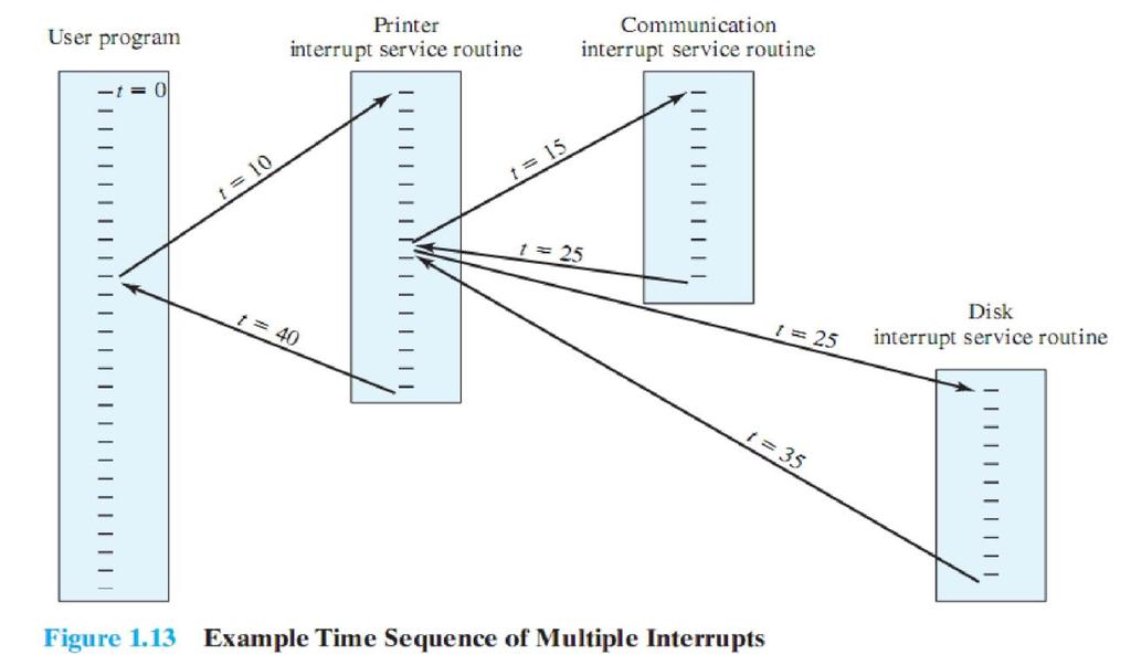
26 Example of Nested Interrupts
27 As an example of this second approach, consider a system with three I/O devices: a printer (priority 2), a disk (priority 4), and a communications line (priority 5). This figure illustrates a possible sequence. 1. A user program begins at t= At t=10, a printer interrupt occurs; user information is placed on the control stack and execution continues at the printer interrupt service routine (ISR). 3. While this routine is still executing, at t =15 a communications interrupt occurs. Because the communications line has higher priority than the printer, the interrupt request is honored. 4. The printer ISR is interrupted, its state is pushed onto the stack, and execution continues at the communications ISR. 5. While this routine is executing, a disk interrupt occurs (t=20). Because this interrupt is of lower priority, it is simply held, and the communications ISR runs to completion. 6. When the communications ISR is complete (t=25), the previous processor state is restored, which is the execution of the printer ISR. 7. However, before even a single instruction in that routine can be executed, the processor honors the higher-priority disk interrupt and transfers control to the disk ISR. 8. Only when that routine is complete (t=35) is the printer ISR resumed. When that routine completes (t=40), control finally returns to the user program. Multiprogramming Processor has more than one program to execute The sequence the programs are executed depend on their relative priority and whether they are waiting for I/O

28 After an interrupt handler completes, control may not return to the program that was executing at the time of the interrupt 5. Memory Hierarchy There is a tradeoff among the three key characteristics of memory: Namely, capacity, access time, and cost. A variety of technologies are used to implement memory systems, and across this spectrum of technologies, the Following relationships hold: Faster access time, greater cost per bit Greater capacity, smaller cost per bit Greater capacity, slower access speed A typical hierarchy is illustrated in this figure.
29 As one goes down the hierarchy, the following occur: a. Decreasing cost per bit b. Increasing capacity c. Increasing access time d. Decreasing frequency of access to the memory by the processor Thus, smaller, more expensive, faster memories are supplemented by larger, cheaper, slower memories. The key to the success of this organization decreasing frequency of access at lower levels. Secondary Memory External, non-volatile memory is also referred to as secondary memory or auxiliary memory. These are used to store program and data files and are usually visible to the programmer only in terms of files and records, as opposed to individual bytes or words. 6. Cache Memory Although cache memory is invisible to the OS, it interacts with other memory management hardware. On all instruction cycles, the processor accesses memory at least once, To fetch the instruction, and often one or more additional times, to fetch operands and/or store results. The rate at which the processor can execute instructions is clearly limited by the memory cycle time I.e. the time it takes to read one word from or write one word to memory. This limitation has been a significant problem because of the persistent mismatch between processor and main memory speeds: Over the years, processor speed has consistently increased more rapidly than memory access speed. We are faced with a trade-off among speed, cost, and size.

30 Ideally, main memory should be built with the same technology as that of the processor registers, giving memory cycle times comparable to processor cycle times. This has always been too expensive a strategy. The solution is to exploit the principle of locality by providing a small, fast memory between the processor and main memory, namely the cache. Principal of Locality: -More details later but in short, Data which is required soon is often close to the current data. If data is referenced, then its neighbour might be needed soon. Cache memory is intended to provide memory access time approaching that of the fastest memories available and at the same time support a large memory size that has the price of less expensive types of semiconductor memories. There is a relatively large and slow main memory together with a smaller, faster cache memory. The cache contains a copy of a portion of main memory. Cache Principles When the processor attempts to read a byte or word of memory, a check is made to determine if the byte or word is in the cache. If so, the byte or word is delivered to the processor. If not, a block of main memory, consisting of some fixed number of bytes, is read into the cache and then the byte or word is delivered to the processor.

31 Because of the phenomenon of locality of reference, when a block of data is fetched into the cache to satisfy a single memory reference, it is likely that many of the nearfuture memory references will be to other bytes in the block. Figure 1.17 depicts the structure of a cache/main memory system. Main memory consists of up to 2 n addressable words, with each word having a unique n-bit address. For mapping purposes, this memory is considered to consist of a number of fixedlength blocks of K words each. i.e., there are M=2 n /K blocks. Cache consists of C slots (also referred to as lines) of K words each, and the number of slots is considerably less than the number of main memory blocks (C << M). Some subset of the blocks of main memory resides in the slots of the cache. If a word in a block of memory that is not in the cache is read, that block is transferred to one of the slots of the cache.

32 Because there are more blocks than slots, an individual slot cannot be uniquely and permanently dedicated to a particular block. Therefore, each slot includes a tag that identifies which particular block is currently being stored. The tag is usually some number of higher-order bits of the address and refers to all addresses that begin with that sequence of bits. Figure 1.18 illustrates the read operation. The processor generates the address, RA, of a word to be read. If the word is contained in the cache, It is delivered to the processor. Otherwise, the block containing that word is loaded into the cache and the word is delivered to the processor.
33 Cache Design Issues We will see that similar design issues must be addressed in dealing with virtual memory and disk cache design. They fall into the following categories: 1. Cache size 2. Block size 3. Mapping function 4. Replacement algorithm 5. Write policy 1. We have already dealt with the issue of cache size. It turns out that reasonably small caches can have a significant impact on performance. 2. Another size issue is that of block size: The unit of data exchanged between cache and main memory. As the block size increases from very small to larger sizes, the hit ratio will at first increase because of the principle of locality: The high probability that data in the vicinity of a referenced word are likely to be referenced in the near future. As the block size increases, more useful data are brought into the cache. The hit ratio will begin to decrease. However, as the block becomes even bigger and the probability of using the newly fetched data becomes less than the probability of reusing the data that have to be moved out of the cache to make room for the new block. 4. Mapping Function When a new block of data is read into the cache, the mapping function determines which cache location the block will occupy. Two constraints affect the design of the mapping function. First, when one block is read in, another may have to be replaced.
34 We would like to do this in such a way as to minimize the probability that we will replace a block that will be needed in the near future. The more flexible the mapping function, the more scope we have to design a replacement algorithm to maximize the hit ratio. Second, the more flexible the mapping function, the more complex is the circuitry required to search the cache to determine if a given block is in the cache. 4. Replacement Algorithm The replacement algorithm chooses, within the constraints of the mapping function, which block to replace when a new block is to be loaded into the cache and the cache already has all slots filled with other blocks. We would like to replace the block that is least likely to be needed again in the near future. Although it is impossible to identify such a block, A reasonably effective strategy is to replace the block that has been in the cache longest with no reference to it. This policy is referred to as the least-recently-used (LRU) algorithm. Hardware mechanisms are needed to identify the least-recently-used block. 5. Write Policy If the contents of a block in the cache are altered, then it is necessary to write it back to main memory before replacing it. The write policy dictates when the memory write operation takes place. At one extreme, the writing can occur every time that the block is updated. At the other extreme, the writing occurs only when the block is replaced. The latter policy minimizes memory write operations but leaves main memory in an obsolete state. This can interfere with multiple-processor operation and with direct memory access by I/O hardware modules. End of Chapter
Q.1 Explain Computer s Basic Elements
 Q.1 Explain Computer s Basic Elements Ans. At a top level, a computer consists of processor, memory, and I/O components, with one or more modules of each type. These components are interconnected in some
B.H.GARDI COLLEGE OF MASTER OF COMPUTER APPLICATION
 Introduction :- An exploits the hardware resources of one or more processors to provide a set of services to system users. The OS also manages secondary memory and I/O devices on behalf of its users. So
Part One provides a background and context for the remainder of this book.
 M01_STAL6329_06_SE_C01.QXD 2/13/08 1:48 PM Page 6 PART ONE Background Part One provides a background and context for the remainder of this book. This part presents the fundamental concepts of computer
Computer System Overview. Chapter 1
 Computer System Overview Chapter 1 Operating System Exploits the hardware resources of one or more processors Provides a set of services to system users Manages secondary memory and I/O devices Basic Elements
Top-Level View of Computer Organization
 Top-Level View of Computer Organization Bởi: Hoang Lan Nguyen Computer Component Contemporary computer designs are based on concepts developed by John von Neumann at the Institute for Advanced Studies
Computer System Overview
 Computer System Overview Chapter 1 Muhammad Adri, MT 1 Operating System Exploits the hardware resources of one or more processors Provides a set of services to system users Manages secondary memory and
CSC 553 Operating Systems
 CSC 553 Operating Systems Lecture 1- Computer System Overview Operating System Exploits the hardware resources of one or more processors Provides a set of services to system users Manages secondary memory
Chapter 1 Computer System Overview
 Operating Systems: Internals and Design Principles Chapter 1 Computer System Overview Ninth Edition By William Stallings Operating System Exploits the hardware resources of one or more processors Provides
Chapter 1 Computer System Overview
 Operating Systems: Internals and Design Principles Chapter 1 Computer System Overview Seventh Edition By William Stallings Objectives of Chapter To provide a grand tour of the major computer system components:
Computer System Overview
 Computer System Overview Operating Systems 2005/S2 1 What are the objectives of an Operating System? 2 What are the objectives of an Operating System? convenience & abstraction the OS should facilitate
Computer System Overview OPERATING SYSTEM TOP-LEVEL COMPONENTS. Simplified view: Operating Systems. Slide 1. Slide /S2. Slide 2.
 BASIC ELEMENTS Simplified view: Processor Slide 1 Computer System Overview Operating Systems Slide 3 Main Memory referred to as real memory or primary memory volatile modules 2004/S2 secondary memory devices
Computer Systems Overview
 Computer Systems Overview Maurizio Pizzonia slides adattate da W. Stalling Operating Systems: Internals and Design Principles http://williamstallings.com/os/os5e.html 1 Basic Elements Processor Main Memory
Chapter 3 - Top Level View of Computer Function
 Chapter 3 - Top Level View of Computer Function Luis Tarrataca luis.tarrataca@gmail.com CEFET-RJ L. Tarrataca Chapter 3 - Top Level View 1 / 127 Table of Contents I 1 Introduction 2 Computer Components
Chapter 12. CPU Structure and Function. Yonsei University
 Chapter 12 CPU Structure and Function Contents Processor organization Register organization Instruction cycle Instruction pipelining The Pentium processor The PowerPC processor 12-2 CPU Structures Processor
Author : Dalbir Singh, Computer Science Deptt. CPU Structure and Functions. 1. Processor Organization
 Author : Dalbir Singh, Computer Science Deptt. CPU Structure and Functions 1. Processor Organization To understand the organization of the CPU, let us consider the requirements placed on the CPU, the things
Operating Systems: Internals and Design Principles, 7/E William Stallings. Chapter 1 Computer System Overview
 Operating Systems: Internals and Design Principles, 7/E William Stallings Chapter 1 Computer System Overview What is an Operating System? Operating system goals: Use the computer hardware in an efficient
Chapter 3. Top Level View of Computer Function and Interconnection. Yonsei University
 Chapter 3 Top Level View of Computer Function and Interconnection Contents Computer Components Computer Function Interconnection Structures Bus Interconnection PCI 3-2 Program Concept Computer components
CPU Structure and Function. Chapter 12, William Stallings Computer Organization and Architecture 7 th Edition
 CPU Structure and Function Chapter 12, William Stallings Computer Organization and Architecture 7 th Edition CPU must: CPU Function Fetch instructions Interpret/decode instructions Fetch data Process data
CPU Structure and Function
 CPU Structure and Function Chapter 12 Lesson 17 Slide 1/36 Processor Organization CPU must: Fetch instructions Interpret instructions Fetch data Process data Write data Lesson 17 Slide 2/36 CPU With Systems
Computer Architecture and Organization (CS-507)
") Computer Architecture and Organization (CS-507) Muhammad Zeeshan Haider Ali Lecturer ISP. Multan ali.zeeshan04@gmail.com https://zeeshanaliatisp.wordpress.com/ Lecture 4 Basic Computer Function, Instruction
Computer Architecture and Organization (CS-507) Muhammad Zeeshan Haider Ali Lecturer ISP. Multan ali.zeeshan04@gmail.com https://zeeshanaliatisp.wordpress.com/ Lecture 4 Basic Computer Function, Instruction
Module 5 - CPU Design
 Module 5 - CPU Design Lecture 1 - Introduction to CPU The operation or task that must perform by CPU is: Fetch Instruction: The CPU reads an instruction from memory. Interpret Instruction: The instruction
SRI VENKATESWARA COLLEGE OF ENGINEERING PENNALUR, SRIPERUMBUDUR TK
 Operating System SRI VENKATESWARA COLLEGE OF ENGINEERING PENNALUR, SRIPERUMBUDUR TK 602117 DEPARTMENT OF COMPUTER SCIENCE AND ENGINEERING & DEPARTMENT OF INFORMATION TECHNOLOGY COMMON COURSE (REGULATIONS
Advanced Parallel Architecture Lesson 3. Annalisa Massini /2015
 Advanced Parallel Architecture Lesson 3 Annalisa Massini - 2014/2015 Von Neumann Architecture 2 Summary of the traditional computer architecture: Von Neumann architecture http://williamstallings.com/coa/coa7e.html
UNIT- 5. Chapter 12 Processor Structure and Function
 UNIT- 5 Chapter 12 Processor Structure and Function CPU Structure CPU must: Fetch instructions Interpret instructions Fetch data Process data Write data CPU With Systems Bus CPU Internal Structure Registers
Eastern Mediterranean University School of Computing and Technology CACHE MEMORY. Computer memory is organized into a hierarchy.
 Eastern Mediterranean University School of Computing and Technology ITEC255 Computer Organization & Architecture CACHE MEMORY Introduction Computer memory is organized into a hierarchy. At the highest
Digital System Design Using Verilog. - Processing Unit Design
 Digital System Design Using Verilog - Processing Unit Design 1.1 CPU BASICS A typical CPU has three major components: (1) Register set, (2) Arithmetic logic unit (ALU), and (3) Control unit (CU) The register
Operating system Dr. Shroouq J.
 2.2.2 DMA Structure In a simple terminal-input driver, when a line is to be read from the terminal, the first character typed is sent to the computer. When that character is received, the asynchronous-communication
UNIT I OPERATING SYSTEMS OVERVIEW
 UNIT I OPERATING SYSTEMS OVERVIEW Computer System Overview-Basic Elements, Instruction Execution, Interrupts, Memory Hierarchy, Cache Memory, Direct Memory Access, Multiprocessor and Multicore Organization.
Chapter 1 Computer System Overview
 Operating Systems: Internals and Design Principles Chapter 1 Computer System Overview Ninth Edition By William Stallings Operating System Exploits the hardware resources of one or more processors Provides
Summary of Computer Architecture
 Summary of Computer Architecture Summary CHAP 1: INTRODUCTION Structure Top Level Peripherals Computer Central Processing Unit Main Memory Computer Systems Interconnection Communication lines Input Output
(Advanced) Computer Organization & Architechture. Prof. Dr. Hasan Hüseyin BALIK (4 th Week)
 Computer Organization & Architechture. Prof. Dr. Hasan Hüseyin BALIK (4 th Week)") + (Advanced) Computer Organization & Architechture Prof. Dr. Hasan Hüseyin BALIK (4 th Week) + Outline 2. The computer system 2.1 A Top-Level View of Computer Function and Interconnection 2.2 Cache Memory
+ (Advanced) Computer Organization & Architechture Prof. Dr. Hasan Hüseyin BALIK (4 th Week) + Outline 2. The computer system 2.1 A Top-Level View of Computer Function and Interconnection 2.2 Cache Memory
William Stallings Computer Organization and Architecture
 William Stallings Computer Organization and Architecture Chapter 11 CPU Structure and Function Rev. 3.2.1 (2005-06) by Enrico Nardelli 11-1 CPU Functions CPU must: Fetch instructions Decode instructions
CPU Structure and Function
 Computer Architecture Computer Architecture Prof. Dr. Nizamettin AYDIN naydin@yildiz.edu.tr nizamettinaydin@gmail.com http://www.yildiz.edu.tr/~naydin CPU Structure and Function 1 2 CPU Structure Registers
William Stallings Computer Organization and Architecture. Chapter 11 CPU Structure and Function
 William Stallings Computer Organization and Architecture Chapter 11 CPU Structure and Function CPU Structure CPU must: Fetch instructions Interpret instructions Fetch data Process data Write data Registers
2016 Pearson Education, Inc., Hoboken, NJ. All rights reserved.
 Lecture slides prepared for Computer Organization and Architecture, 10/e, by William Stallings, Chapter 3 A Top Level View of Computer Function and Interconnection. 1 At a top level, a computer consists
Computer System Overview
 Computer System Overview Introduction A computer system consists of hardware system programs application programs 2 Operating System Provides a set of services to system users (collection of service programs)
William Stallings Computer Organization and Architecture 10 th Edition Pearson Education, Inc., Hoboken, NJ. All rights reserved.
 + William Stallings Computer Organization and Architecture 10 th Edition 2016 Pearson Education, Inc., Hoboken, NJ. All rights reserved. 2 + Chapter 4 Cache Memory 3 Location Internal (e.g. processor registers,
William Stallings Computer Organization and Architecture 10 th Edition Pearson Education, Inc., Hoboken, NJ. All rights reserved.
 + William Stallings Computer Organization and Architecture 10 th Edition 2016 Pearson Education, Inc., Hoboken, NJ. All rights reserved. 2 + Chapter 3 A Top-Level View of Computer Function and Interconnection
Advanced Parallel Architecture Lesson 3. Annalisa Massini /2015
 Advanced Parallel Architecture Lesson 3 Annalisa Massini - Von Neumann Architecture 2 Two lessons Summary of the traditional computer architecture Von Neumann architecture http://williamstallings.com/coa/coa7e.html
Running Applications
 Running Applications Computer Hardware Central Processing Unit (CPU) CPU PC IR MAR MBR I/O AR I/O BR To exchange data with memory Brain of Computer, controls everything Few registers PC (Program Counter):
Today: Computer System Overview (Stallings, chapter ) Next: Operating System Overview (Stallings, chapter ,
 Next: Operating System Overview (Stallings, chapter ,") Lecture Topics Today: Computer System Overview (Stallings, chapter 1.1-1.8) Next: Operating System Overview (Stallings, chapter 2.1-2.4, 2.8-2.10) 1 Announcements Syllabus and calendar available Consulting
Lecture Topics Today: Computer System Overview (Stallings, chapter 1.1-1.8) Next: Operating System Overview (Stallings, chapter 2.1-2.4, 2.8-2.10) 1 Announcements Syllabus and calendar available Consulting
Cache memory. Lecture 4. Principles, structure, mapping
 Cache memory Lecture 4 Principles, structure, mapping Computer memory overview Computer memory overview By analyzing memory hierarchy from top to bottom, the following conclusions can be done: a. Cost
(Advanced) Computer Organization & Architechture. Prof. Dr. Hasan Hüseyin BALIK (3 rd Week)
 Computer Organization & Architechture. Prof. Dr. Hasan Hüseyin BALIK (3 rd Week)") + (Advanced) Computer Organization & Architechture Prof. Dr. Hasan Hüseyin BALIK (3 rd Week) + Outline 2. The computer system 2.1 A Top-Level View of Computer Function and Interconnection 2.2 Cache Memory
+ (Advanced) Computer Organization & Architechture Prof. Dr. Hasan Hüseyin BALIK (3 rd Week) + Outline 2. The computer system 2.1 A Top-Level View of Computer Function and Interconnection 2.2 Cache Memory
William Stallings Computer Organization and Architecture 8 th Edition. Chapter 12 Processor Structure and Function
 William Stallings Computer Organization and Architecture 8 th Edition Chapter 12 Processor Structure and Function CPU Structure CPU must: Fetch instructions Interpret instructions Fetch data Process data
WEEK 7. Chapter 4. Cache Memory Pearson Education, Inc., Hoboken, NJ. All rights reserved.
 WEEK 7 + Chapter 4 Cache Memory Location Internal (e.g. processor registers, cache, main memory) External (e.g. optical disks, magnetic disks, tapes) Capacity Number of words Number of bytes Unit of Transfer
CPE300: Digital System Architecture and Design
 CPE300: Digital System Architecture and Design Fall 2011 MW 17:30-18:45 CBC C316 Virtual Memory 11282011 http://www.egr.unlv.edu/~b1morris/cpe300/ 2 Outline Review Cache Virtual Memory Projects 3 Memory
a process may be swapped in and out of main memory such that it occupies different regions
 Virtual Memory Characteristics of Paging and Segmentation A process may be broken up into pieces (pages or segments) that do not need to be located contiguously in main memory Memory references are dynamically
M. Sc (CS) (II Semester) Examination, Subject: Computer System Architecture Paper Code: M.Sc-CS-203. Time: Three Hours] [Maximum Marks: 60
![M. Sc (CS) (II Semester) Examination, Subject: Computer System Architecture Paper Code: M.Sc-CS-203. Time: Three Hours] [Maximum Marks: 60](/thumbs/87/96339673.jpg "M. Sc (CS) (II Semester) Examination, Subject: Computer System Architecture Paper Code: M.Sc-CS-203. Time: Three Hours] [Maximum Marks: 60") M. Sc (CS) (II Semester) Examination, 2012-13 Subject: Computer System Architecture Paper Code: M.Sc-CS-203 Time: Three Hours] [Maximum Marks: 60 Note: Question Number 1 is compulsory. Answer any four
M. Sc (CS) (II Semester) Examination, 2012-13 Subject: Computer System Architecture Paper Code: M.Sc-CS-203 Time: Three Hours] [Maximum Marks: 60 Note: Question Number 1 is compulsory. Answer any four
Computer Architecture and Organization. Instruction Sets: Addressing Modes and Formats
 Computer Architecture and Organization Instruction Sets: Addressing Modes and Formats Addressing Modes Immediate Direct Indirect Register Register Indirect Displacement (Indexed) Stack Immediate Addressing
Basic Processing Unit: Some Fundamental Concepts, Execution of a. Complete Instruction, Multiple Bus Organization, Hard-wired Control,
 UNIT - 7 Basic Processing Unit: Some Fundamental Concepts, Execution of a Complete Instruction, Multiple Bus Organization, Hard-wired Control, Microprogrammed Control Page 178 UNIT - 7 BASIC PROCESSING
Chapter 4. MARIE: An Introduction to a Simple Computer. Chapter 4 Objectives. 4.1 Introduction. 4.2 CPU Basics
 Chapter 4 Objectives Learn the components common to every modern computer system. Chapter 4 MARIE: An Introduction to a Simple Computer Be able to explain how each component contributes to program execution.
CSCI-375 Operating Systems
 CSCI-375 Operating Systems Lecture 2 Note: Many slides and/or pictures in the following are adapted from: slides 2005 Silberschatz, Galvin, and Gagne Some slides and/or pictures in the following are adapted
PESIT Bangalore South Campus
 INTERNAL ASSESSMENT TEST I Date: 30/08/2017 Max Marks: 40 Subject & Code: Computer Organization 15CS34 Semester: III (A & B) Name of the faculty: Mrs.Sharmila Banu.A Time: 8.30 am 10.00 am Answer any FIVE
Operating Systems: Internals and Design Principles. Chapter 1 Computer System Overview Seventh Edition By William Stallings
 Operating Systems: Internals and Design Principles Chapter 1 Computer System Overview Seventh Edition By William Stallings Operating Systems: Internals and Design Principles No artifact designed by man
Introduction to Operating Systems. Chapter Chapter
 Introduction to Operating Systems Chapter 1 1.3 Chapter 1.5 1.9 Learning Outcomes High-level understand what is an operating system and the role it plays A high-level understanding of the structure of
Chapter 11. Instruction Sets: Addressing Modes and Formats. Yonsei University
 Chapter 11 Instruction Sets: Addressing Modes and Formats Contents Addressing Pentium and PowerPC Addressing Modes Instruction Formats Pentium and PowerPC Instruction Formats 11-2 Common Addressing Techniques
Chapter 8. Operating System Support. Yonsei University
 Chapter 8 Operating System Support Contents Operating System Overview Scheduling Memory Management Pentium II and PowerPC Memory Management 8-2 OS Objectives & Functions OS is a program that Manages the
UNIT 1. INTRODUCTION: COMPUTER & OPERATING SYSTEMS
 This document can be downloaded from www.chetanahegde.in with most recent updates. 1 UNIT 1. INTRODUCTION: COMPUTER & OPERATING SYSTEMS 1.1 BASIC ELEMENTS A computer consists of processor, memory and I/O
Major Requirements of an OS
 Process CSCE 351: Operating System Kernels Major Requirements of an OS Interleave the execution of several processes to maximize processor utilization while providing reasonable response time Allocate
Misc. Third Generation Batch Multiprogramming. Fourth Generation Time Sharing. Last Time Evolution of OSs
 Third Generation Batch Multiprogramming Misc. Problem: but I/O still expensive; can happen in middle of job Idea: have a pool of ready jobs in memory, switch to one when another needs I/O When one job
Chapter 8 Virtual Memory
 Chapter 8 Virtual Memory Contents Hardware and control structures Operating system software Unix and Solaris memory management Linux memory management Windows 2000 memory management Characteristics of
Introduction to Operating. Chapter Chapter
 Introduction to Operating Systems Chapter 1 1.3 Chapter 1.5 1.9 Learning Outcomes High-level understand what is an operating system and the role it plays A high-level understanding of the structure of
Addresses in the source program are generally symbolic. A compiler will typically bind these symbolic addresses to re-locatable addresses.
 1 Memory Management Address Binding The normal procedures is to select one of the processes in the input queue and to load that process into memory. As the process executed, it accesses instructions and
Processing Unit CS206T
 Processing Unit CS206T Microprocessors The density of elements on processor chips continued to rise More and more elements were placed on each chip so that fewer and fewer chips were needed to construct
William Stallings Computer Organization and Architecture 8 th Edition. Chapter 11 Instruction Sets: Addressing Modes and Formats
 William Stallings Computer Organization and Architecture 8 th Edition Chapter 11 Instruction Sets: Addressing Modes and Formats Addressing Modes Immediate Direct Indirect Register Register Indirect Displacement
Introduction to Operating Systems. Chapter Chapter
 Introduction to Operating Systems Chapter 1 1.3 Chapter 1.5 1.9 Learning Outcomes High-level understand what is an operating system and the role it plays A high-level understanding of the structure of
Process Description and Control. Chapter 3
 Process Description and Control Chapter 3 Contents Process states Process description Process control Unix process management Process From processor s point of view execute instruction dictated by program
Operating System: an Overview. Lucia Dwi Krisnawati, MA
 Operating System: an Overview Lucia Dwi Krisnawati, MA What is an Operating System? A program that acts as an intermediary between a user of a computer and the computer hardware. Operating system goals:
Chapter 14 - Processor Structure and Function
 Chapter 14 - Processor Structure and Function Luis Tarrataca luis.tarrataca@gmail.com CEFET-RJ L. Tarrataca Chapter 14 - Processor Structure and Function 1 / 94 Table of Contents I 1 Processor Organization
Input Output (IO) Management
 Management") Input Output (IO) Management Prof. P.C.P. Bhatt P.C.P Bhatt OS/M5/V1/2004 1 Introduction Humans interact with machines by providing information through IO devices. Manyon-line services are availed through
Input Output (IO) Management Prof. P.C.P. Bhatt P.C.P Bhatt OS/M5/V1/2004 1 Introduction Humans interact with machines by providing information through IO devices. Manyon-line services are availed through
A Review on Cache Memory with Multiprocessor System
 A Review on Cache Memory with Multiprocessor System Chirag R. Patel 1, Rajesh H. Davda 2 1,2 Computer Engineering Department, C. U. Shah College of Engineering & Technology, Wadhwan (Gujarat) Abstract
MARTHANDAM COLLEGE OF ENGINEERING AND TECHNOLOGY DEPARTMENT OF INFORMATION TECHNOLOGY TWO MARK QUESTIONS AND ANSWERS
 MARTHANDAM COLLEGE OF ENGINEERING AND TECHNOLOGY DEPARTMENT OF INFORMATION TECHNOLOGY TWO MARK QUESTIONS AND ANSWERS SUB NAME: COMPUTER ORGANIZATION AND ARCHITECTTURE SUB CODE: CS 2253 YEAR/SEM:II/IV Marthandam
Chapter 4. Cache Memory. Yonsei University
 Chapter 4 Cache Memory Contents Computer Memory System Overview Cache Memory Principles Elements of Cache Design Pentium 4 and Power PC Cache 4-2 Key Characteristics 4-3 Location Processor Internal (main)
Chapter 2 Instruction Set Architecture
 Chapter 2 Instruction Set Architecture Course Outcome (CO) - CO2 Describe the architecture and organization of computer systems Program Outcome (PO) PO1 Apply knowledge of mathematics, science and engineering
Embedded Systems Dr. Santanu Chaudhury Department of Electrical Engineering Indian Institute of Technology, Delhi
 Embedded Systems Dr. Santanu Chaudhury Department of Electrical Engineering Indian Institute of Technology, Delhi Lecture - 13 Virtual memory and memory management unit In the last class, we had discussed
2 MARKS Q&A 1 KNREDDY UNIT-I
 2 MARKS Q&A 1 KNREDDY UNIT-I 1. What is bus; list the different types of buses with its function. A group of lines that serves as a connecting path for several devices is called a bus; TYPES: ADDRESS BUS,
CSc33200: Operating Systems, CS-CCNY, Fall 2003 Jinzhong Niu December 10, Review
 CSc33200: Operating Systems, CS-CCNY, Fall 2003 Jinzhong Niu December 10, 2003 Review 1 Overview 1.1 The definition, objectives and evolution of operating system An operating system exploits and manages
OPERATING SYSTEMS. Goals of the Course. This lecture will cover: This Lecture will also cover:
 OPERATING SYSTEMS This lecture will cover: Goals of the course Definitions of operating systems Operating system goals What is not an operating system Computer architecture O/S services This Lecture will
Addressing Modes. Immediate Direct Indirect Register Register Indirect Displacement (Indexed) Stack
 Stack") Addressing Modes Addressing Modes and Formats Nizamettin AYDIN naydin@yildiz.edu.tr http://www.yildiz.edu.tr/~naydin http://akademik.bahcesehir.edu.tr/~naydin Immediate Direct Indirect Register Register
Addressing Modes Addressing Modes and Formats Nizamettin AYDIN naydin@yildiz.edu.tr http://www.yildiz.edu.tr/~naydin http://akademik.bahcesehir.edu.tr/~naydin Immediate Direct Indirect Register Register
INPUT/OUTPUT ORGANIZATION
 INPUT/OUTPUT ORGANIZATION Accessing I/O Devices I/O interface Input/output mechanism Memory-mapped I/O Programmed I/O Interrupts Direct Memory Access Buses Synchronous Bus Asynchronous Bus I/O in CO and
Overview of Syllabus and Class Policies. Chapter 0
 Overview of Syllabus and Class Policies 1 Chapter 0 2 Syllabus and Class Policies Instructor Hao Zhang Assistant Professor Department of Computer Science Office: BB 250 Email: hzhang@mines.edu URL: http://inside.mines.edu/~hzhang
Operating Systems CMPSCI 377 Spring Mark Corner University of Massachusetts Amherst
 Operating Systems CMPSCI 377 Spring 2017 Mark Corner University of Massachusetts Amherst Last Class: Intro to OS An operating system is the interface between the user and the architecture. User-level Applications
Computer-System Architecture (cont.) Symmetrically Constructed Clusters (cont.) Advantages: 1. Greater computational power by running applications
 Symmetrically Constructed Clusters (cont.) Advantages: 1. Greater computational power by running applications") Computer-System Architecture (cont.) Symmetrically Constructed Clusters (cont.) Advantages: 1. Greater computational power by running applications concurrently on all computers in the cluster. Disadvantages:
Computer-System Architecture (cont.) Symmetrically Constructed Clusters (cont.) Advantages: 1. Greater computational power by running applications concurrently on all computers in the cluster. Disadvantages:
MICROPROCESSOR MEMORY ORGANIZATION
 MICROPROCESSOR MEMORY ORGANIZATION 1 3.1 Introduction 3.2 Main memory 3.3 Microprocessor on-chip memory management unit and cache 2 A memory unit is an integral part of any microcomputer, and its primary
Introduction. CS3026 Operating Systems Lecture 01
 Introduction CS3026 Operating Systems Lecture 01 One or more CPUs Device controllers (I/O modules) Memory Bus Operating system? Computer System What is an Operating System An Operating System is a program
Last 2 Classes: Introduction to Operating Systems & C++ tutorial. Today: OS and Computer Architecture
 Last 2 Classes: Introduction to Operating Systems & C++ tutorial User apps OS Virtual machine interface hardware physical machine interface An operating system is the interface between the user and the
CS370 Operating Systems
 CS370 Operating Systems Colorado State University Yashwant K Malaiya Fall 2016 Lecture 2 Slides based on Text by Silberschatz, Galvin, Gagne Various sources 1 1 2 System I/O System I/O (Chap 13) Central
Unit 2 : Computer and Operating System Structure
 Unit 2 : Computer and Operating System Structure Lesson 1 : Interrupts and I/O Structure 1.1. Learning Objectives On completion of this lesson you will know : what interrupt is the causes of occurring
ASSEMBLY LANGUAGE MACHINE ORGANIZATION
 ASSEMBLY LANGUAGE MACHINE ORGANIZATION CHAPTER 3 1 Sub-topics The topic will cover: Microprocessor architecture CPU processing methods Pipelining Superscalar RISC Multiprocessing Instruction Cycle Instruction
The Instruction Set. Chapter 5
 The Instruction Set Architecture Level(ISA) Chapter 5 1 ISA Level The ISA level l is the interface between the compilers and the hardware. (ISA level code is what a compiler outputs) 2 Memory Models An
k -bit address bus n-bit data bus Control lines ( R W, MFC, etc.)
") THE MEMORY SYSTEM SOME BASIC CONCEPTS Maximum size of the Main Memory byte-addressable CPU-Main Memory Connection, Processor MAR MDR k -bit address bus n-bit data bus Memory Up to 2 k addressable locations
THE MEMORY SYSTEM SOME BASIC CONCEPTS Maximum size of the Main Memory byte-addressable CPU-Main Memory Connection, Processor MAR MDR k -bit address bus n-bit data bus Memory Up to 2 k addressable locations
IT 540 Operating Systems ECE519 Advanced Operating Systems
 IT 540 Operating Systems ECE519 Advanced Operating Systems Prof. Dr. Hasan Hüseyin BALIK (3 rd Week) (Advanced) Operating Systems 3. Process Description and Control 3. Outline What Is a Process? Process
The CPU and Memory. How does a computer work? How does a computer interact with data? How are instructions performed? Recall schematic diagram:
 The CPU and Memory How does a computer work? How does a computer interact with data? How are instructions performed? Recall schematic diagram: 1 Registers A register is a permanent storage location within
Chapter 4. MARIE: An Introduction to a Simple Computer
 Chapter 4 MARIE: An Introduction to a Simple Computer Chapter 4 Objectives Learn the components common to every modern computer system. Be able to explain how each component contributes to program execution.
Chapter One. Introduction to Computer System
 Principles of Programming-I / 131101 Prepared by: Dr. Bahjat Qazzaz -------------------------------------------------------------------------------------------- Chapter One Introduction to Computer System
DC57 COMPUTER ORGANIZATION JUNE 2013
 Q2 (a) How do various factors like Hardware design, Instruction set, Compiler related to the performance of a computer? The most important measure of a computer is how quickly it can execute programs.
Operating System Control Structures
 Operating System Control Structures Information about the current status of each process and resource Tables are constructed for each entity the operating system manages 26 Memory Tables Allocation of
Main Points of the Computer Organization and System Software Module
 Main Points of the Computer Organization and System Software Module You can find below the topics we have covered during the COSS module. Reading the relevant parts of the textbooks is essential for a
Chapter 6 Memory 11/3/2015. Chapter 6 Objectives. 6.2 Types of Memory. 6.1 Introduction
 Chapter 6 Objectives Chapter 6 Memory Master the concepts of hierarchical memory organization. Understand how each level of memory contributes to system performance, and how the performance is measured.
Memory Hierarchy. Goal: Fast, unlimited storage at a reasonable cost per bit.
 Memory Hierarchy Goal: Fast, unlimited storage at a reasonable cost per bit. Recall the von Neumann bottleneck - single, relatively slow path between the CPU and main memory. Fast: When you need something