CS6710 Tool Suite. Verilog is the Key Tool
|
|
|
- Mildred Riley
- 6 years ago
- Views:
Transcription
1 CS6710 Tool Suite Verilog-XL Behavioral Verilog Your Library Cadence SOC Encounter Synopsys Synthesis Structural Verilog Circuit Layout CSI Verilog-XL AutoRouter Cadence Virtuoso Layout LVS Layout-XL Cadence Composer Schematic Verilog is the Key Tool Behavioral Verilog is synthesized into Structural Verilog Structural Verilog represents net-lists From Behavioral From Schematics From makemem High-level (Synthesizer will flatten these) Verilog-XL is used for testing all designs Behavioral & Structural & Schematic & High-level 1
2 Verilog has a Split Personality Hardware Description Language (HDL) Reliably & Readably Create hardware Document hardware The wire-list function fits into HDL Testbench creation language Create external test environment Time & Voltage Files & messages Are these two tasks Related? Compatible? Verilog as HDL (AHT) C-like hardware description language. But what does C have to do with hardware? Marketing hype cast into vital tools Verilog is ill-suited to its use. Verbose Feels to me like I are tricking it Good engineers Use only a subset of the language. Keep Learning. Try before they buy. Demo today. 2
3 Synthesis This lecture is only about synthesis... Quick Review Module name (args ); begin input ; // define inputs output ; // define outputs wire ; // internal wires reg ; // internal regs, possibly output // the parts of the module body are // executed concurrently <continuous assignments> <always blocks> endmodule 3
4 Quick Review Continuous assignments to wire vars assign variable = exp; Result in combinational logic Procedural assignment to reg vars Always inside procedural blocks (always blocks in particular for synthesis) blocking variable = exp; non-blocking variable <= exp; Can result in combinational or sequential logic Procedural Control Statements Conditional Statement if ( <expression> ) <statement> if ( <expression> ) <statement> else <statement> else is always associated with the closest previous if that lacks an else. You can use begin-end blocks to make it more clear if (index >0) if (rega > regb) result = rega; else result = regb; 4
5 Multi-Way Decisions Standard if-else-if syntax If ( <expression> ) <statement> else if ( <expression> ) <statement> else if ( <expression> ) <statement> else <statement> Verilog Description Styles Verilog supports a variety of description styles Structural explicit structure of the circuit e.g., each logic gate instantiated and connected to others Behavioral program describes input/output behavior of circuit many structural implementations could have same behavior e.g., different implementation of one Boolean function 5
6 Synthesis: Data Types Possible Values: 0: logic 0, false 1: logic 1, true Z: High impedance Digital Hardware The domain of Verilog Either logic (gates) Or storage (registers & latches) Verilog has two relevant data types wire reg Synthesis: Data Types Register declarations reg a; \\ a scalar register reg [3:0] b; \\ a 4-bit vector register output g; \\ an output can be a reg reg g; output reg g; \\ Verilog 2001 syntax Wire declarations wire d; \\ a scalar wire wire [3:0] e; \\ a 4-bit vector wire output f; \\ an output can be a wire 6
7 Parameters Used to define constants parameter size = 16, foo = 8; wire [size-1:0] bus; \\ defines a 15:0 bus Synthesis: Assign Statement The assign statement creates combinational logic assign LHS = expression; LHS can only be wire type expression can contain either wire or reg type mixed with operators wire a,c; reg b;output out; assign a = b & c; assign out = ~(a & b); \\ output as wire wire [15:0] sum, a, b; wire cin, cout; assign {cout,sum} = a + b + cin; 7
8 Synthesis: Basic Operators Bit-Wise Logical ~ (not), & (and), (or), ^ (xor), ^~ or ~^ (xnor) Simple Arithmetic Operators Binary: +, - Unary: - Negative numbers stored as 2 s complement Relational Operators <, >, <=, >=, ==,!= Logical Operators! (not), && (and), (or) assign a = (b > b0110) && (c <= 4 d5); assign a = (b > b0110) &&!(c > 4 d5); Synthesis: Operand Length When operands are of unequal bit length, the shorter operator is zero-filled in the most significant bit position wire [3:0] sum, a, b; wire cin, cout, d, e, f, g; assign sum = f & a; assign sum = f a; assign sum = {d, e, f, g} & a; assign sum = {4{f}} b; assign sum = {4{f == g}} & (a + b); assign sum[0] = g & a[2]; assign sum[2:0] = {3{g}} & a[3:1]; 8
9 Synthesis: More Operators Concatenation {a,b} {4{a==b}} { a,b,4 b1001,{4{a==b}} } Shift (logical shift) << left shift >> right shift assign a = b >> 2; // shift right 2, division by 4 assign a = b << 1; // shift left 1, multiply by 2 Arithmetic assign a = b * c; // multiply b times c assign a = b * d2; // multiply b times constant (=2) assign a = b / b10; // divide by 2 (constant only) assign a = b % h3; // b modulo 3 (constant only) Synthesis: Operand Length Operator length is set to the longest member (both RHS & LHS are considered). Be careful. wire [3:0] sum, a, b; wire cin, cout, d, e, f, g; wire[4:0]sum1; assign {cout,sum} = a + b + cin; assign {cout,sum} = a + b + {4 b0,cin}; assign sum1 = a + b; assign sum = (a + b) >> 1; // what is wrong? 9
10 Synthesis: Extra Operators Funky Conditional cond_exp? true_expr : false_expr wire [3:0] a,b,c; wire d; assign a = (b == c)? (c + d1): o5; // good luck Reduction Logical Named for impact on your recreational time Unary operators that perform bit-wise operations on a single operand, reduce it to one bit &, ~&,, ~, ^, ~^, ^~ assign d = &a ~^b ^ ^~c; Synthesis: Assign Statement The assign statement is sufficient to create all combinational logic What about this: assign a = ~(b & c); assign c = ~(d & a); 10
11 Simple Behavioral Module // Behavioral model of NAND gate module NAND (out, in1, in2); output out; input in1, in2; assign out = ~(in1 & in2); endmodule Simple Structural Module // Structural Module for NAND gate module NAND (out, in1, in2); output out; input in1, in2; wire w1; // call existing modules by name // module-name ID (signal-list); AND2 u1(w1, in1, in2); INV u2(out,w1); endmodule 11
12 Simple Structural Module // Structural Module for NAND gate module NAND (out, in1, in2); output out; input in1, in2; wire w1; // call existing modules by name // module-name ID (signal-list); // can connect ports by name... AND2 u1(.q(w1),.a(in1),.b(in2)); INV u2(.a(w1),.q(out)); endmodule Procedural Assignment Assigns values to register types They do not have a duration The register holds the value until the next procedural assignment to that variable The occur only within procedural blocks initial and always initial is NOT supported for synthesis! They are triggered when the flow of execution reaches them 12
13 Always Blocks When is an always block executed? always Starts at time 0 or b or c) Whenever there is a change on a, b, or c Used to describe combinational logic foo) Whenever foo goes from low to high Used to describe sequential logic bar) Whenever bar goes from high to low Synthesis: Always Statement The always statement creates LHS = controls when LHS can only be reg type expression can contain either wire or reg type mixed with operators Logic reg c, b; wire a; b) c = ~(a & b); c = ~(a & b); Storage reg Q; wire clk; clk) Q <= D; 13
14 Procedural NAND gate // Procedural model of NAND gate module NAND (out, in1, in2); output out; reg out; input in1, in2; // always executes when in1 or in2 // change value or in2) begin out = ~(in1 & in2); end endmodule Procedural NAND gate // Procedural model of NAND gate module NAND (out, in1, in2); output out; reg out; input in1, in2; // always executes when in1 or in2 // change value or in2) begin out <= ~(in1 & in2); end endmodule Is out combinational? 14
15 Synthesis: NAND gate input in1, in2; reg n1, n2; wire n3,n4; // is this a flip-flop? or in2) n1 = ~(in1 & in2); n2 = ~(in1 & in2); assign n3 = ~(in1 & in2); nand u1(n4, in1, in2); Notice always block for combinational logic Full sensitivity list, works Can then use the always goodies Is this a good coding style? Procedural Assignments Assigns values to reg types Only useable inside a procedural block Usually synthesizes to a register But, under the right conditions, can also result in combinational circuits Blocking procedural assignment LHS = timing-control exp a = #10 1; Must be executed before any assignments that follow (timing control is optional) Assignments proceed in order even if no timing is given Non-Blocking procedural assignment LHS <= timing-control exp b <= 2; Evaluated simultaneously when block starts Assignment occurs at the end of the (optional) time-control 15
16 Procedural Synthesis Synthesis ignores all that timing stuff So, what does it mean to have blocking vs. non-blocking assignment for synthesis? begin A=B; B=A; end begin A=Y; B=A; end?? begin A<=B; B<=A; end begin A<=Y; B<=A; end begin A = Y; B = A; end Synthesized Circuits begin A <= Y; B <= A; end begin B = A; A = Y; end Y Y D Q A clk D Q A clk D Q B clk D Q B clk A B A B 16
17 Synthesized Circuits clk) begin A = Y; B = A; end Y D Q A clk A clk) begin B = A; A = Y; end clk D Q B clk B clk) begin A <= Y; B <= A; end Y clk) begin B <= A; A <= Y clk end D Q A clk D Q B clk A B Assignments and Synthesis Note that different circuit structures result from different types of procedural assignments Therefore you can t mix assignment types in the same always block And you can t use different assignment types to assign the same register either Non-blocking is often a better model for hardware Real hardware is often concurrent 17
18 Comparator Example Using continuous assignment Concurrent execution of assignments Module comp (a, b, Cgt, Clt, Cne); parameter n = 4; input [n-1:0] a, b; output Cgt, Clt, Cne; assign Cgt = (a > b); assign Clt = (a < b); assign Cne = (a!= b); endmodule Comparator Example Using procedural assignment Non-blocking assignment implies concurrent Module comp (a, b, Cgt, Clt, Cne); parameter n = 4; input [n-1:0] a, b; output Cgt, Clt, Cne; reg Cgt, Clt, Cne; or b) Cgt <= (a > a); Clt <= (a < b); Cne <= (a!= b); endmodule 18
19 Modeling a Flip Flop Use an always block to wait for clock edge Module dff (clk, d, q); input clk, d; output q; reg q; clk) d = q; endmodule Synthesis: Always Statement This is a simple D Flip-Flop reg Q; clk) Q <= clk) is the sensitivity list The Q <= D; is the block part The block part is always entered whenever the sensitivity list becomes true (positive edge of clk) The LHS of the <= must be of data type reg The RHS of the <= may use reg or wire 19
20 Synthesis: Always Statement This is an asynchronous clear D Flip-Flop reg Q; clk, posedge rst) if (rst) Q <= b0; else Q <= D; Notice, instead of or Verilog 2001 Positive reset (how does the edge play?) Synthesis: Always Statement reg Q; clk, posedge rst, posedge set) if (rst) Q <= b0; else if (set) Q <= b1; else Q <= D; What is this? What is synthesized? syn-f06> beh2str foo.v foo_str.v UofU_Digital.db 20

21 Synthesis: Always Statement reg Q; clk, posedge rst, posedge set) if (rst) Q <= b0; else if (set) Q <= b1; else Q <= D; What is this? What is synthesized? Synthesis: Always Statement reg Q; clk, posedge rst, posedge set) if (rst) Q <= b0; else if (set) Q <= b1; else Q <= D; What is this? What is synthesized? 21
22 Synthesis: Always Statement reg Q; clk) if (rst) Q <= b0; else if (set) Q <= b1; else Q <= D; What is this? Synthesis: Always Statement reg Q; clk) if (rst) Q <= b0; else if (set) Q <= b1; else Q <= D; What is this? Inferred memory devices in process in routine set line 5 in file '/home/elb/ic_cad/syn-f06/set.v'. =============================================================================== Register Name Type Width Bus MB AR AS SR SS ST ====================================================== Q_reg Flip-flop 1 N N N N N N N =============================================================================== 22
23 module foo ( clk, rst, set, D, Q ); input clk, rst, set, D; output Q; wire N3, n2, n4; dff Q_reg (.D(N3),.G(clk),.CLR(n2),.Q(Q) ); tiehi U6 (.Y(n2) ); nor2 U7 (.A(rst),.B(n4),.Y(N3) ); nor2 U8 (.A(D),.B(set),.Y(n4) ); endmodule Synthesis: Always Statement reg P,Q; reg [3:0] R; clk) begin Q <= D; P <= Q; R <= R + h1; end What is this? Will it synthesize? Simulate? 23
24 Synthesis: Always Statement module testme ( D, P, Q, R, clk ); output [3:0] R; input D, clk; output P, Q; wire N0, N1, N2, N3, n1, n7, n8, n9; dff Q_reg (.D(D),.G(clk),.CLR(n1),.Q(Q) ); dff P_reg (.D(Q),.G(clk),.CLR(n1),.Q(P) ); dff R_reg_0_ (.D(N0),.G(clk),.CLR(n1),.Q(R[0]) ); dff R_reg_1_ (.D(N1),.G(clk),.CLR(n1),.Q(R[1]) ); dff R_reg_2_ (.D(N2),.G(clk),.CLR(n1),.Q(R[2]) ); dff R_reg_3_ (.D(N3),.G(clk),.CLR(n1),.Q(R[3]) ); tiehi U9 (.Y(n1) ); xor2 U10 (.A(R[3]),.B(n7),.Y(N3) ); nor2 U11 (.A(n8),.B(n9),.Y(n7) ); xor2 U12 (.A(n8),.B(n9),.Y(N2) ); invx1 U13 (.A(R[2]),.Y(n9) ); nand2 U14 (.A(R[1]),.B(R[0]),.Y(n8) ); xor2 U15 (.A(R[1]),.B(R[0]),.Y(N1) ); invx1 U16 (.A(R[0]),.Y(N0) ); endmodule Synthesis: Always Statement This is a simple D Flip-Flop So is this reg Q; clk) Q <= D; reg Q; clk) Q = D; = is for blocking assignments <= is for nonblocking assignments 24
25 Constants parameter used to define constants parameter size = 16, foo = 8; wire [size-1:0] bus; \\ defines a 15:0 bus externally modifiable scope is local to module localparam not externally modifiable localparam width = size * foo; `define macro definition `define value 7 d53 assign a = (sel == `value) & b; scope is from here on out Example: Counter module counter (clk, clr, load, in, count); parameter width=8; input clk, clr, load; input [width-1 : 0] in; output [width-1 : 0] count; reg [width-1 : 0] tmp; clk or negedge clr) begin if (!clr) tmp = 0; else if (load) tmp = in; else tmp=tmp+ 1; end assign count = tmp; endmodule 25
26 Synthesis: Modules module the_top (clk, rst, a, b, sel, result); input clk, rst; input [3:0] a,b; input [2:0] sel; output reg [3:0] result; wire[3:0] sum, dif, alu; adder u0(a,b,sum); subber u1(.subtrahend(a),.subtractor(b),.difference(dif)); assign alu = {4{(sel == b000)}} & sum {4{(sel == b001)}} & dif; clk or posedge rst) if(rst) result <= h0; else result <= alu; endmodule Synthesis: Modules // Verilog 1995 syntax module adder (e,f,g); parameter SIZE=2; input [SIZE-1:0] e, f; output [SIZE-1:0] g; g = e + f; endmodule // Verilog 2001 syntax module subber #(parameter SIZE = 3) (input [SIZE-1:0] c,d, output [SIZE-1:0]difference); difference = c - d; endmodule 26
27 Synthesis: Modules module the_top (clk, rst, a, b, sel, result); parameter SIZE = 4; input clk, rst; input [SIZE-1:0] a,b; input [2:0] sel; output reg [SIZE-1:0] result; wire[size-1:0] sum, dif, alu; adder #(.SIZE(SIZE)) u0(a,b,sum); subber #(4) u1(.c(a),.d(b),.difference(dif)); assign alu = {SIZE{sel == b000}} & sum {SIZE{sel == b001}} & dif; clk or posedge rst) if(rst) result <= h0; else result <= alu; endmodule Multi-Way Decisions Standard if-else-if syntax If ( <expression> ) <statement> else if ( <expression> ) <statement> else if ( <expression> ) <statement> else <statement> 27
28 Priority vs. Parallel Choice (if) module priority (a, b, c, d, sel, z); input a,b,c,d; input [3:0] sel; output z; reg z; or b or c or d or sel) begin z = 0; if (sel[0]) z = a; if (sel[1]) z = b; if (sel[2]) z = c; if (sel[3]) z = d; end endmodule Priority vs. Parallel Choice module parallel (a, b, c, d, sel, z); input a,b,c,d; input [3:0] sel; output z; reg z; or b or c or d or sel) begin z = 0; if (sel[3]) z = d; else if (sel[2]) z = c; else if (sel[1]) z = b; else if (sel[0]) z = a; end endmodule 28
29 Priority Encoders Priority Encoders 29
30 Case Statements Multi-way decision on a single expression case ( <expresion> ) <expression>: <statement> <expression>, <expression>: <statement> <expression>: <statement> default: <statement> endcase Case Example reg [1:0] sel; reg [15:0] in0, in1, in2, in3, out; case (sel) 2 b00: out = in0; 2 b01: out = in1; 2 b10: out = in2; 2 b11: out = in3; endcase 30
31 Another Case Example // simple counter next-state logic // one-hot state encoding parameter [2:0] s0=3 h1, s1=3 h2, s2=3 h4; reg[2:0] state, next_state; or state) input begin case (state) state s0: if (input) next_state = s1; else next_state = s0; s1: next_state = s2; s2: next_state = s0; endcase end next_state Weird Case Example Verilog allows you to put a value in the case slot, and test which variable currently has that value reg [ 2:0] curr_state, next_state; parameter s1=3 b001, s2=3 b010, s3=3 b100 case (1) curr_state[0] : next_state = s2; curr_state[1] : next_state = s3; curr_state[2] : next_state = s1; endcase 31
32 Latch Inference Incompletely specified if and case statements cause the synthesizer to infer latches begin if (cond) data_out <= data_in; end This infers a latch because it doesn t specify what to do when cond = 0 Fix by adding an else In a case, fix by including default: Full vs. Parallel Case statements check each case in sequence A case statement is full if all possible outcomes are accounted for A case statement is parallel if the stated alternatives are mutually exclusive These distinctions make a difference in how cases are translated to circuits Similar to the if statements previously described 32
![Case full-par example // full and parallel = combinational logic module full-par (slct, a, b, c, d, out); input [1:0] slct; input a, b, c, d; output out; reg out; // optimized away in this example](/docs-images/77/75501176/images/33-0.jpg "always @(slct or a or b or c or d) case (slct) 2 b11 : out <= a; 2 b10 : out <= b; 2 b01 : out <= c; default : out <= d; // really 2 b10 endcase endmodule Synthesis Result Note that full-par results")
33 Case full-par example // full and parallel = combinational logic module full-par (slct, a, b, c, d, out); input [1:0] slct; input a, b, c, d; output out; reg out; // optimized away in this example or a or b or c or d) case (slct) 2 b11 : out <= a; 2 b10 : out <= b; 2 b01 : out <= c; default : out <= d; // really 2 b10 endcase endmodule Synthesis Result Note that full-par results in combinational logic 33
![Case notfull-par example // a latch is synthesized because case is not full module notfull-par (slct, a, b, c, d, out); input [1:0] slct; input a, b, c, d; output out; reg out; // NOT optimized](/docs-images/77/75501176/images/34-0.jpg "away in this example always @(slct or a or b or c) case (slct) 2 b11 : out <= a; 2 b10 : out <= b; 2 b01 : out <= c; endcase endmodule Synthesized Circuit Because it s not full, a latch is")
34 Case notfull-par example // a latch is synthesized because case is not full module notfull-par (slct, a, b, c, d, out); input [1:0] slct; input a, b, c, d; output out; reg out; // NOT optimized away in this example or a or b or c) case (slct) 2 b11 : out <= a; 2 b10 : out <= b; 2 b01 : out <= c; endcase endmodule Synthesized Circuit Because it s not full, a latch is inferred 34
;... always @(slct or a or b or c) casez (slct) 2 b1? : out <= a; 2 b?")
35 Case full-notpar example // because case is not parallel - priority encoding // but it is still full, so no latch // this uses a casez which treats? as don t-care module full-notpar (slct, a, b, c, out);... or a or b or c) casez (slct) 2 b1? : out <= a; 2 b?1 : out <= b; default : out <= c; endcase endmodule Synthesized Circuit It s full, so it s combinational, but it s not parallel so it s a priority circuit instead of a check all in parallel circuit 35
;... always @(slct or a or b or c) casez (slct) 2 b1? : out <= a; 2 b?")
36 Case notfull-notpar example // because case is not parallel - priority encoding // because case is not full - latch is inferred // uses a casez which treats? as don t-care module full-notpar (slct, a, b, c, out);... or a or b or c) casez (slct) 2 b1? : out <= a; 2 b?1 : out <= b; endcase endmodule Synthesized Circuit Not full and not parallel, infer a latch 36

37 Verification CASE matches all (works like ===) CASEX uses z, x,? as don t care CASEZ uses z,? as don t care Beware: Matches first valid case Synthesis Get off my Case CASE works like == CASEX uses? as don t care CASEZ uses? as don t care Get off my Case Order Matters 37

38 Get off my Case Link FSM Description One simple way: break it up like a schematic A combinational block for next_state generation A combinational block for output generation A sequential block to store the current state Mealy only in Next state Logic Next_state clk State current State output Logic outputs 38
39 Modeling State Machines // General view module FSM (clk, in, out); input clk, in; output out; reg out; // state variables reg [1:0] state; // next state variable reg [1:0] next_state; // state register state = next_state; or in); // next-state logic // compute next state and output logic // make sure every local variable has an // assignment in this block endmodule in Next state Logic Next_state clk State State FSM Desciption 39
40 Verilog Version module moore (clk, clr, insig, outsig); input clk, clr, insig; output outsig; // define state encodings as parameters parameter [1:0] s0 = 2'b00, s1 = 2'b01,s2 = 2'b10, s3 = 2'b11; // define reg vars for state register // and next_state logic reg [1:0] state, next_state; //define state register (with //synchronous active-high clear) clk) begin if (clr) state = s0; else state = next_state; end // define combinational logic for // next_state or state) begin case (state) s0: if (insig) next_state = s1; else next_state = s0; s1: if (insig) next_state = s2; else next_state = s1; s2: if (insig) next_state = s3; else next_state = s2; s3: if (insig) next_state = s1; else next_state = s0; endcase end // assign outsig as continuous assign assign outsig = ((state == s1) (state == s3)); endmodule Verilog Version module moore (clk, clr, insig, outsig); input clk, clr, insig; output outsig; // define state encodings as parameters parameter [1:0] s0 = 2'b00, s1 = 2'b01, s2 = 2'b10, s3 = 2'b11; // define reg vars for state register and next_state logic reg [1:0] state, next_state; //define state register (with synchronous active-high clear) clk) begin if (clr) state = s0; else state = next_state; end 40
41 Verilog Version Continued... // define combinational logic for next_state or state) begin case (state) s0: if (insig) next_state = s1; else next_state = s0; s1: if (insig) next_state = s2; else next_state = s1; s2: if (insig) next_state = s3; else next_state = s2; s3: if (insig) next_state = s1; else next_state = s0; endcase end Verilog Version Continued... // now set the outsig. This could also be done in an always // block... but in that case, outsig would have to be // defined as a reg. assign outsig = ((state == s1) (state == s3)); endmodule 41
42 Unsupported for Synthesis Delay (Synopsys will ignore # s) initial blocks (use explicit resets) repeat wait fork event deassign force release More Unsupported Stuff You cannot assign the same reg variable in more than one procedural block // don t do this a) out = in1; b) out = in2; 42
43 Combinational Always Blocks Be careful or in1 or in2) if (sel == 1) if (sel == 1) out = in1; out = in1; else out = in2; else out = in2; Which one is a good mux? Sync vs. Async Register Reset // synchronous reset (active-high reset) clk) if (reset) state = s0; else state = s1; // async reset (active-low reset) clk or negedge reset) if (reset == 0) state = s0; else state = s1; 43
44 Finite State Machine 0 S S1 1 S2 S3 1 Four in a Row S4 1 1 Textbook FSM 44
45 Textbook FSM Comments Polarity? Always use <= for FF Documented FSM 45

46 Waveform Test Bench Waveform Pay attention to first few cycles... 46
47 FSM FSM 47
48 FSM One-Hot FSM 48

49 One-Hot FSM Counting Oops 49
50 No Asynchronous Sets That s better 50
51 Synchronous Clear Link Synchronous Clear 51

52 Synchronous Clear Is asynchronous clear really asynchronous? What about set-up & hold with respect to clock edge? ROM vs. Verilog 52

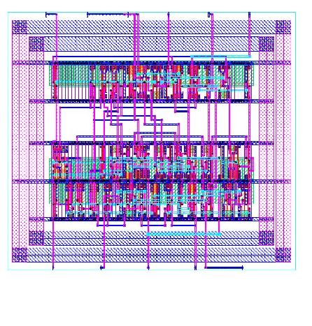
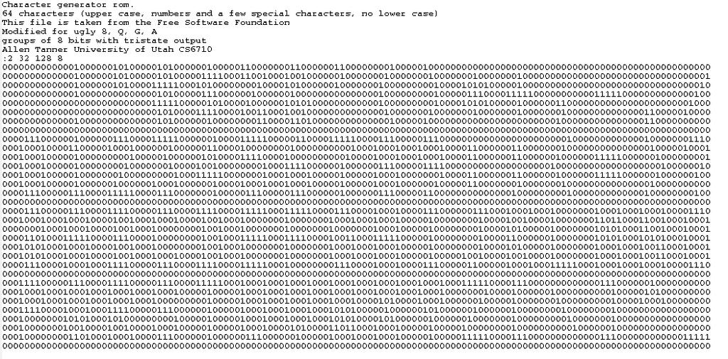
53 ROM vs. Verilog ROM vs. Verilog 53

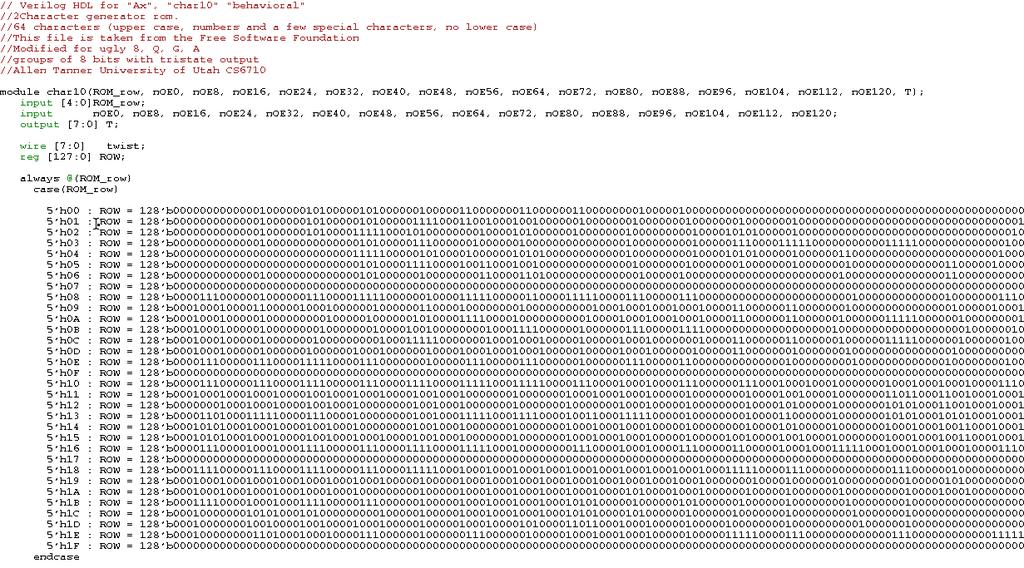
54 ROM vs. Verilog ROM vs. Verilog Link 54
55 ROM vs. Verilog ROM vs. Verilog 55
CS6710 Tool Suite. Verilog is the Key Tool. Verilog as HDL (AHT) Verilog has a Split Personality. Quick Review. Synthesis
 Verilog has a Split Personality. Quick Review. Synthesis") CS6710 Tool Suite Verilog is the Key Tool Verilog-XL Behavioral Verilog Your Library AutoRouter Cadence SOC Encounter Cadence Virtuoso Layout Synopsys Synthesis Circuit Layout CSI LVS Layout-XL Structural
CS6710 Tool Suite Verilog is the Key Tool Verilog-XL Behavioral Verilog Your Library AutoRouter Cadence SOC Encounter Cadence Virtuoso Layout Synopsys Synthesis Circuit Layout CSI LVS Layout-XL Structural
Veriolog Overview. CS/EE 3710 Fall 2010
 Veriolog Overview CS/EE 3710 Fall 2010 Hardware Description Languages HDL Designed to be an alternative to schematics for describing hardware systems Two main survivors VHDL Commissioned by DOD Based on
Hardware Description Languages. Veriolog Overview. CS/EE 3710 Fall Verilog. Verilog Origins. Quick Review (2001 syntax) Quick Review HDL
 Quick Review HDL") Veriolog Overview CS/EE 3710 Fall 2010 Hardware Description Languages HDL Designed to be an alternative to schematics for describing hardware systems Two main survivors VHDL Commissioned by DOD ased on
Veriolog Overview CS/EE 3710 Fall 2010 Hardware Description Languages HDL Designed to be an alternative to schematics for describing hardware systems Two main survivors VHDL Commissioned by DOD ased on
CSE140L: Components and Design Techniques for Digital Systems Lab
 CSE140L: Components and Design Techniques for Digital Systems Lab Tajana Simunic Rosing Source: Vahid, Katz, Culler 1 Announcements & Outline Lab 4 due; demo signup times listed on the cse140l site Check
EEL 4783: HDL in Digital System Design
 EEL 4783: HDL in Digital System Design Lecture 15: Logic Synthesis with Verilog Prof. Mingjie Lin 1 Verilog Synthesis Synthesis vs. Compilation Descriptions mapped to hardware Verilog design patterns for
CSE140L: Components and Design
 CSE140L: Components and Design Techniques for Digital Systems Lab Tajana Simunic Rosing Source: Vahid, Katz, Culler 1 Grade distribution: 70% Labs 35% Lab 4 30% Lab 3 20% Lab 2 15% Lab 1 30% Final exam
Synthesizable Verilog
 Synthesizable Verilog Courtesy of Dr. Edwards@Columbia, and Dr. Franzon@NCSU http://csce.uark.edu +1 (479) 575-6043 yrpeng@uark.edu Design Methodology Structure and Function (Behavior) of a Design HDL
EECS150 - Digital Design Lecture 10 Logic Synthesis
 EECS150 - Digital Design Lecture 10 Logic Synthesis September 26, 2002 John Wawrzynek Fall 2002 EECS150 Lec10-synthesis Page 1 Logic Synthesis Verilog and VHDL stated out as simulation languages, but quickly
Verilog for Synthesis Ing. Pullini Antonio
 Verilog for Synthesis Ing. Pullini Antonio antonio.pullini@epfl.ch Outline Introduction to Verilog HDL Describing combinational logic Inference of basic combinational blocks Describing sequential circuits
EECS150 - Digital Design Lecture 10 Logic Synthesis
 EECS150 - Digital Design Lecture 10 Logic Synthesis February 13, 2003 John Wawrzynek Spring 2003 EECS150 Lec8-synthesis Page 1 Logic Synthesis Verilog and VHDL started out as simulation languages, but
Logic Synthesis. EECS150 - Digital Design Lecture 6 - Synthesis
 Logic Synthesis Verilog and VHDL started out as simulation languages, but quickly people wrote programs to automatically convert Verilog code into low-level circuit descriptions (netlists). EECS150 - Digital
Synthesis vs. Compilation Descriptions mapped to hardware Verilog design patterns for best synthesis. Spring 2007 Lec #8 -- HW Synthesis 1
 Verilog Synthesis Synthesis vs. Compilation Descriptions mapped to hardware Verilog design patterns for best synthesis Spring 2007 Lec #8 -- HW Synthesis 1 Logic Synthesis Verilog and VHDL started out
Synthesis of Language Constructs. 5/10/04 & 5/13/04 Hardware Description Languages and Synthesis
 Synthesis of Language Constructs 1 Nets Nets declared to be input or output ports are retained Internal nets may be eliminated due to logic optimization User may force a net to exist trireg, tri0, tri1
ECE 2300 Digital Logic & Computer Organization. More Sequential Logic Verilog
 ECE 2300 Digital Logic & Computer Organization Spring 2018 More Sequential Logic Verilog Lecture 7: 1 Announcements HW3 will be posted tonight Prelim 1 Thursday March 1, in class Coverage: Lectures 1~7
Introduction to Verilog/System Verilog
 NTUEE DCLAB Feb. 27, 2018 Introduction to Verilog/System Verilog Presenter: Yao-Pin Wang 王耀斌 Advisor: Prof. Chia-Hsiang Yang 楊家驤 Dept. of Electrical Engineering, NTU National Taiwan University What is
Computer Aided Design Basic Syntax Gate Level Modeling Behavioral Modeling. Verilog
 Verilog Radek Pelánek and Šimon Řeřucha Contents 1 Computer Aided Design 2 Basic Syntax 3 Gate Level Modeling 4 Behavioral Modeling Computer Aided Design Hardware Description Languages (HDL) Verilog C
Why Should I Learn This Language? VLSI HDL. Verilog-2
 Verilog Why Should I Learn This Language? VLSI HDL Verilog-2 Different Levels of Abstraction Algorithmic the function of the system RTL the data flow the control signals the storage element and clock Gate
Chap 6 Introduction to HDL (d)
") Design with Verilog Chap 6 Introduction to HDL (d) Credit to: MD Rizal Othman Faculty of Electrical & Electronics Engineering Universiti Malaysia Pahang Ext: 6036 VERILOG HDL Basic Unit A module Module
Design with Verilog Chap 6 Introduction to HDL (d) Credit to: MD Rizal Othman Faculty of Electrical & Electronics Engineering Universiti Malaysia Pahang Ext: 6036 VERILOG HDL Basic Unit A module Module
Digital Design with SystemVerilog
 Digital Design with SystemVerilog Prof. Stephen A. Edwards Columbia University Spring 25 Synchronous Digital Design Combinational Logic Sequential Logic Summary of Modeling Styles Testbenches Why HDLs?
In this lecture, we will go beyond the basic Verilog syntax and examine how flipflops and other clocked circuits are specified.
 1 In this lecture, we will go beyond the basic Verilog syntax and examine how flipflops and other clocked circuits are specified. I will also introduce the idea of a testbench as part of a design specification.
Verilog Behavioral Modeling
 Verilog Behavioral Modeling Lan-Da Van ( 范倫達 ), Ph. D. Department of Computer Science National Chiao Tung University Taiwan, R.O.C. Spring, 2017 ldvan@cs.nctu.edu.tw http://www.cs.nctu.edu.tw/~ldvan/ Source:
FPGA Design Challenge :Techkriti 14 Digital Design using Verilog Part 1
 FPGA Design Challenge :Techkriti 14 Digital Design using Verilog Part 1 Anurag Dwivedi Digital Design : Bottom Up Approach Basic Block - Gates Digital Design : Bottom Up Approach Gates -> Flip Flops Digital
Speaker: Kayting Adviser: Prof. An-Yeu Wu Date: 2009/11/23
 98-1 Under-Graduate Project Synthesis of Combinational Logic Speaker: Kayting Adviser: Prof. An-Yeu Wu Date: 2009/11/23 What is synthesis? Outline Behavior Description for Synthesis Write Efficient HDL
Digital Design with FPGAs. By Neeraj Kulkarni
 Digital Design with FPGAs By Neeraj Kulkarni Some Basic Electronics Basic Elements: Gates: And, Or, Nor, Nand, Xor.. Memory elements: Flip Flops, Registers.. Techniques to design a circuit using basic
Verilog. What is Verilog? VHDL vs. Verilog. Hardware description language: Two major languages. Many EDA tools support HDL-based design
 Verilog What is Verilog? Hardware description language: Are used to describe digital system in text form Used for modeling, simulation, design Two major languages Verilog (IEEE 1364), latest version is
Lecture #2: Verilog HDL
 Lecture #2: Verilog HDL Paul Hartke Phartke@stanford.edu Stanford EE183 April 8, 2002 EE183 Design Process Understand problem and generate block diagram of solution Code block diagram in verilog HDL Synthesize
Verilog introduction. Embedded and Ambient Systems Lab
 Verilog introduction Embedded and Ambient Systems Lab Purpose of HDL languages Modeling hardware behavior Large part of these languages can only be used for simulation, not for hardware generation (synthesis)
Lecture 15: System Modeling and Verilog
 Lecture 15: System Modeling and Verilog Slides courtesy of Deming Chen Intro. VLSI System Design Outline Outline Modeling Digital Systems Introduction to Verilog HDL Use of Verilog HDL in Synthesis Reading
Sequential Logic Design
 Sequential Logic Design Design of Digital Circuits 2017 Srdjan Capkun Onur Mutlu (Guest starring: Frank K. Gürkaynak and Aanjhan Ranganathan) http://www.syssec.ethz.ch/education/digitaltechnik_17 Adapted
EECS150 - Digital Design Lecture 5 - Verilog Logic Synthesis
 EECS150 - Digital Design Lecture 5 - Verilog Logic Synthesis Jan 31, 2012 John Wawrzynek Spring 2012 EECS150 - Lec05-verilog_synth Page 1 Outline Quick review of essentials of state elements Finite State
Introduction to Digital Design with Verilog HDL
 Introduction to Digital Design with Verilog HDL Modeling Styles 1 Levels of Abstraction n Behavioral The highest level of abstraction provided by Verilog HDL. A module is implemented in terms of the desired
Writing Circuit Descriptions 8
 8 Writing Circuit Descriptions 8 You can write many logically equivalent descriptions in Verilog to describe a circuit design. However, some descriptions are more efficient than others in terms of the
ECEN 468 Advanced Logic Design
 ECEN 468 Advanced Logic Design Lecture 28: Synthesis of Language Constructs Synthesis of Nets v An explicitly declared net may be eliminated in synthesis v Primary input and output (ports) are always retained
The Verilog Language COMS W Prof. Stephen A. Edwards Fall 2002 Columbia University Department of Computer Science
 The Verilog Language COMS W4995-02 Prof. Stephen A. Edwards Fall 2002 Columbia University Department of Computer Science The Verilog Language Originally a modeling language for a very efficient event-driven
Digital Design (VIMIAA01) Introduction to the Verilog HDL
 Introduction to the Verilog HDL") BUDAPEST UNIVERSITY OF TECHNOLOGY AND ECONOMICS FACULTY OF ELECTRICAL ENGINEERING AND INFORMATICS DEPARTMENT OF MEASUREMENT AND INFORMATION SYSTEMS Digital Design (VIMIAA01) Introduction to the Verilog
BUDAPEST UNIVERSITY OF TECHNOLOGY AND ECONOMICS FACULTY OF ELECTRICAL ENGINEERING AND INFORMATICS DEPARTMENT OF MEASUREMENT AND INFORMATION SYSTEMS Digital Design (VIMIAA01) Introduction to the Verilog
Course Topics - Outline
 Course Topics - Outline Lecture 1 - Introduction Lecture 2 - Lexical conventions Lecture 3 - Data types Lecture 4 - Operators Lecture 5 - Behavioral modeling A Lecture 6 Behavioral modeling B Lecture 7
Modeling Sequential Circuits in Verilog
 Modeling Sequential Circuits in Verilog COE 202 Digital Logic Design Dr. Muhamed Mudawar King Fahd University of Petroleum and Minerals Presentation Outline Modeling Latches and Flip-Flops Blocking versus
EECS150 - Digital Design Lecture 4 - Verilog Introduction. Outline
 EECS150 - Digital Design Lecture 4 - Verilog Introduction Feb 3, 2009 John Wawrzynek Spring 2009 EECS150 - Lec05-Verilog Page 1 Outline Background and History of Hardware Description Brief Introduction
Introduction to Verilog HDL. Verilog 1
 Introduction to HDL Hardware Description Language (HDL) High-Level Programming Language Special constructs to model microelectronic circuits Describe the operation of a circuit at various levels of abstraction
Synthesis of Combinational and Sequential Circuits with Verilog
 Synthesis of Combinational and Sequential Circuits with Verilog What is Verilog? Hardware description language: Are used to describe digital system in text form Used for modeling, simulation, design Two
Chapter 2 Using Hardware Description Language Verilog. Overview
 Chapter 2 Using Hardware Description Language Verilog CSE4210 Winter 2012 Mokhtar Aboelaze based on slides by Dr. Shoab A. Khan Overview Algorithm development isa usually done in MATLAB, C, or C++ Code
14:332:231 DIGITAL LOGIC DESIGN. Hardware Description Languages
 14:332:231 DIGITAL LOGIC DESIGN Ivan Marsic, Rutgers University Electrical & Computer Engineering Fall 2013 Lecture #22: Introduction to Verilog Hardware Description Languages Basic idea: Language constructs
N-input EX-NOR gate. N-output inverter. N-input NOR gate
 Hardware Description Language HDL Introduction HDL is a hardware description language used to design and document electronic systems. HDL allows designers to design at various levels of abstraction. It
Verilog Coding Guideline
 Verilog Coding Guideline Digital Circuit Lab TA: Po-Chen Wu Outline Introduction to Verilog HDL Verilog Syntax Combinational and Sequential Logics Module Hierarchy Write Your Design Finite State Machine
Lecture 32: SystemVerilog
 Lecture 32: SystemVerilog Outline SystemVerilog module adder(input logic [31:0] a, input logic [31:0] b, output logic [31:0] y); assign y = a + b; Note that the inputs and outputs are 32-bit busses. 17:
EN2911X: Reconfigurable Computing Topic 02: Hardware Definition Languages
 EN2911X: Reconfigurable Computing Topic 02: Hardware Definition Languages Professor Sherief Reda http://scale.engin.brown.edu School of Engineering Brown University Spring 2014 1 Introduction to Verilog
This Lecture. Some components (useful for the homework) Verilog HDL (will continue next lecture)
 Verilog HDL (will continue next lecture)") Last Lecture The basic component of a digital circuit is the MOS transistor Transistor have instrinsic resistance and capacitance, so voltage values in the circuit take some time to change ( delay ) There
Last Lecture The basic component of a digital circuit is the MOS transistor Transistor have instrinsic resistance and capacitance, so voltage values in the circuit take some time to change ( delay ) There
A Brief Introduction to Verilog Hardware Definition Language (HDL)
") www.realdigital.org A Brief Introduction to Verilog Hardware Definition Language (HDL) Forward Verilog is a Hardware Description language (HDL) that is used to define the structure and/or behavior of digital
www.realdigital.org A Brief Introduction to Verilog Hardware Definition Language (HDL) Forward Verilog is a Hardware Description language (HDL) that is used to define the structure and/or behavior of digital
Verilog for High Performance
 Verilog for High Performance Course Description This course provides all necessary theoretical and practical know-how to write synthesizable HDL code through Verilog standard language. The course goes
Online Verilog Resources
 EECS 427 Discussion 6: Verilog HDL Reading: Many references EECS 427 F08 Discussion 6 1 Online Verilog Resources ASICs the book, Ch. 11: http://www.ge.infn.it/~pratolo/verilog/verilogtutorial.pdf it/ pratolo/verilog/verilogtutorial
a, b sum module add32 sum vector bus sum[31:0] sum[0] sum[31]. sum[7:0] sum sum overflow module add32_carry assign
![a, b sum module add32 sum vector bus sum[31:0] sum[0] sum[31]. sum[7:0] sum sum overflow module add32_carry assign](/thumbs/91/106466219.jpg "a, b sum module add32 sum vector bus sum[31:0] sum[0] sum[31]. sum[7:0] sum sum overflow module add32_carry assign") I hope you have completed Part 1 of the Experiment. This lecture leads you to Part 2 of the experiment and hopefully helps you with your progress to Part 2. It covers a number of topics: 1. How do we specify
I hope you have completed Part 1 of the Experiment. This lecture leads you to Part 2 of the experiment and hopefully helps you with your progress to Part 2. It covers a number of topics: 1. How do we specify
ECE 353 Lab 4. Verilog Review. Professor Daniel Holcomb With material by Professor Moritz and Kundu UMass Amherst Fall 2016
 ECE 353 Lab 4 Verilog Review Professor Daniel Holcomb With material by Professor Moritz and Kundu UMass Amherst Fall 2016 Recall What You Will Do Design and implement a serial MIDI receiver Hardware in
VLSI Design 13. Introduction to Verilog
 Last module: Sequential circuit design Design styles This module Synthesis Brief introduction to Verilog Synthesis in the Design Flow Designer Tasks Tools Architect Logic Designer Circuit Designer Define
Under-Graduate Project Logic Design with Behavioral Models
 97-1 1 Under-Graduate Project Logic Design with Behavioral Models Speaker: 吳佳謙 Adviser: Prof. An-Yeu Wu Date: 2008/10/20 ACCESS IC LAB Operation Assignment Outline Blocking and non-blocking Appendix pp.
HDLs and SystemVerilog. Digital Computer Design
 HDLs and SystemVerilog Digital Computer Design Logic Arrays Gates can be organized into regular arrays. If the connections are made programmable, these logic arrays can be configured to perform any function
Outline. EECS Components and Design Techniques for Digital Systems. Lec 11 Putting it all together Where are we now?
 Outline EECS 5 - Components and Design Techniques for Digital Systems Lec Putting it all together -5-4 David Culler Electrical Engineering and Computer Sciences University of California Berkeley Top-to-bottom
ENGN1640: Design of Computing Systems Topic 02: Design/Lab Foundations
 ENGN1640: Design of Computing Systems Topic 02: Design/Lab Foundations Professor Sherief Reda http://scale.engin.brown.edu School of Engineering Brown University Spring 2017 1 Topics 1. Programmable logic
Design Using Verilog
 EGC220 Design Using Verilog Baback Izadi Division of Engineering Programs bai@engr.newpaltz.edu Basic Verilog Lexical Convention Lexical convention are close to C++. Comment // to the of the line. /* to
Verilog Tutorial. Introduction. T. A.: Hsueh-Yi Lin. 2008/3/12 VLSI Digital Signal Processing 2
 Verilog Tutorial T. A.: Hsueh-Yi Lin Introduction 2008/3/12 VLSI Digital Signal Processing 2 Verilog: A common language for industry HDL is a common way for hardware design Verilog VHDL Verilog is widely
Hardware Description Language VHDL (1) Introduction
 Introduction") Hardware Description Language VHDL (1) Introduction Digital Radiation Measurement and Spectroscopy NE/RHP 537 Introduction Hardware description language (HDL) Intended to describe circuits textually, for
Hardware Description Language VHDL (1) Introduction Digital Radiation Measurement and Spectroscopy NE/RHP 537 Introduction Hardware description language (HDL) Intended to describe circuits textually, for
EECS 427 Lecture 14: Verilog HDL Reading: Many handouts/references. EECS 427 W07 Lecture 14 1
 EECS 427 Lecture 14: Verilog HDL Reading: Many handouts/references EECS 427 W07 Lecture 14 1 Online Verilog Resources ASICs the book, Ch. 11: http://www.ge.infn.it/~pratolo/verilog/verilogtutorial.pdf
ECE 353 Lab 4. Verilog Review. Professor Daniel Holcomb UMass Amherst Fall 2017
 ECE 353 Lab 4 Verilog Review Professor Daniel Holcomb UMass Amherst Fall 2017 What You Will Do In Lab 4 Design and implement a serial MIDI receiver Hardware in an Altera Complex Programmable Logic Device
CSE140L: Components and Design Techniques for Digital Systems Lab. Verilog HDL. Instructor: Mohsen Imani UC San Diego. Source: Eric Crabill, Xilinx
 CSE140L: Components and Design Techniques for Digital Systems Lab Verilog HDL Instructor: Mohsen Imani UC San Diego Source: Eric Crabill, Xilinx 1 Hardware description languages Used to describe & model
Lecture 12 VHDL Synthesis
 CPE 487: Digital System Design Spring 2018 Lecture 12 VHDL Synthesis Bryan Ackland Department of Electrical and Computer Engineering Stevens Institute of Technology Hoboken, NJ 07030 1 What is Synthesis?
Verilog Design Principles
 16 h7fex // 16-bit value, low order 4 bits unknown 8 bxx001100 // 8-bit value, most significant 2 bits unknown. 8 hzz // 8-bit value, all bits high impedance. Verilog Design Principles ECGR2181 Extra Notes
Hardware Description Languages: Verilog
 Hardware Description Languages: Verilog Verilog Structural Models (Combinational) Behavioral Models Syntax Examples CS 150 - Fall 2005 - Lecture #4: Verilog - 1 Quick History of HDLs ISP (circa 1977) -
ENGN1640: Design of Computing Systems Topic 02: Design/Lab Foundations
 ENGN1640: Design of Computing Systems Topic 02: Design/Lab Foundations Professor Sherief Reda http://scale.engin.brown.edu School of Engineering Brown University Spring 2016 1 Topics 1. Programmable logic
Verilog Fundamentals. Shubham Singh. Junior Undergrad. Electrical Engineering
 Verilog Fundamentals Shubham Singh Junior Undergrad. Electrical Engineering VERILOG FUNDAMENTALS HDLs HISTORY HOW FPGA & VERILOG ARE RELATED CODING IN VERILOG HDLs HISTORY HDL HARDWARE DESCRIPTION LANGUAGE
EN164: Design of Computing Systems Lecture 06: Lab Foundations / Verilog 2
 EN164: Design of Computing Systems Lecture 06: Lab Foundations / Verilog 2 Professor Sherief Reda http://scaleenginbrownedu Electrical Sciences and Computer Engineering School of Engineering Brown University
Federal Urdu University of Arts, Science and Technology, Islamabad VLSI SYSTEM DESIGN. Prepared By: Engr. Yousaf Hameed.
 VLSI SYSTEM DESIGN Prepared By: Engr. Yousaf Hameed Lab Engineer BASIC ELECTRICAL & DIGITAL SYSTEMS LAB DEPARTMENT OF ELECTRICAL ENGINEERING VLSI System Design 1 LAB 01 Schematic Introduction to DSCH and
Chapter 3: Dataflow Modeling
 Chapter 3: Dataflow Modeling Prof. Soo-Ik Chae Digital System Designs and Practices Using Verilog HDL and FPGAs @ 2008, John Wiley 3-1 Objectives After completing this chapter, you will be able to: Describe
ECE 551 Digital System Design and Synthesis. Instructor: Kewal K. Saluja. Midterm Exam
 Last (family) name: First (given) name: Student I.D. #: Department of Electrical and Computer Engineering University of Wisconsin - Madison ECE 551 Digital System Design and Synthesis Instructor: Kewal
ECE 4514 Digital Design II. Spring Lecture 7: Dataflow Modeling
 ECE 4514 Digital Design II Lecture 7: Dataflow Modeling A language Lecture Today's topic Dataflow Modeling input input input module output output Model with submodules and gates = Structural Model with
Quick Introduction to SystemVerilog: Sequental Logic
 ! Quick Introduction to SystemVerilog: Sequental Logic Lecture L3 8-545 Advanced Digital Design ECE Department Many elements Don Thomas, 24, used with permission with credit to G. Larson Today Quick synopsis
A Verilog Primer. An Overview of Verilog for Digital Design and Simulation
 A Verilog Primer An Overview of Verilog for Digital Design and Simulation John Wright Vighnesh Iyer Department of Electrical Engineering and Computer Sciences College of Engineering, University of California,
VHDL: RTL Synthesis Basics. 1 of 59
 VHDL: RTL Synthesis Basics 1 of 59 Goals To learn the basics of RTL synthesis. To be able to synthesize a digital system, given its VHDL model. To be able to relate VHDL code to its synthesized output.
ECEN 468 Advanced Digital System Design
 ECEN 468 Advanced Digital System Design Lecture 22: Verilog Behavioral Description Structural vs. Behavioral Descriptions module my_module(); assign ; // continuous assignment and (); // instantiation
EE178 Lecture Verilog FSM Examples. Eric Crabill SJSU / Xilinx Fall 2007
 EE178 Lecture Verilog FSM Examples Eric Crabill SJSU / Xilinx Fall 2007 In Real-time Object-oriented Modeling, Bran Selic and Garth Gullekson view a state machine as: A set of input events A set of output
Abi Farsoni, Department of Nuclear Engineering and Radiation Health Physics, Oregon State University
 Hardware description language (HDL) Intended to describe circuits textually, for a computer to read Evolved starting in the 1970s and 1980s Popular languages today include: VHDL Defined in 1980s by U.S.
Contents. Appendix D Verilog Summary Page 1 of 16
 Appix D Verilog Summary Page 1 of 16 Contents Appix D Verilog Summary... 2 D.1 Basic Language Elements... 2 D.1.1 Keywords... 2 D.1.2 Comments... 2 D.1.3 Identifiers... 2 D.1.4 Numbers and Strings... 3
Hardware Description Languages: Verilog. Quick History of HDLs. Verilog/VHDL. Design Methodology. Verilog Introduction. Verilog.
 Hardware Description Languages: Verilog Quick History of HDLs Verilog Structural Models (Combinational) Behavioral Models Syntax Examples CS 150 - Fall 2005 - Lecture #4: Verilog - 1 ISP (circa 1977) -
Lab #1. Topics. 3. Introduction to Verilog 2/8/ Programmable logic. 2. Design Flow. 3. Verilog --- A Hardware Description Language
 Lab #1 Lecture 8, 9, &10: FPGA Dataflow and Verilog Modeling February 9, 11, 13, 2015 Prof R Iris Bahar Lab #1 is posted on the webpage wwwbrownedu/departments/engineering/courses/engn1640 Note for problem
Verilog Sequential Logic. Verilog for Synthesis Rev C (module 3 and 4)
") Verilog Sequential Logic Verilog for Synthesis Rev C (module 3 and 4) Jim Duckworth, WPI 1 Sequential Logic Module 3 Latches and Flip-Flops Implemented by using signals in always statements with edge-triggered
Verilog Sequential Logic Verilog for Synthesis Rev C (module 3 and 4) Jim Duckworth, WPI 1 Sequential Logic Module 3 Latches and Flip-Flops Implemented by using signals in always statements with edge-triggered
Verilog Module 1 Introduction and Combinational Logic
 Verilog Module 1 Introduction and Combinational Logic Jim Duckworth ECE Department, WPI 1 Module 1 Verilog background 1983: Gateway Design Automation released Verilog HDL Verilog and simulator 1985: Verilog
Digital Circuit Design and Language. Datapath Design. Chang, Ik Joon Kyunghee University
 Digital Circuit Design and Language Datapath Design Chang, Ik Joon Kyunghee University Typical Synchronous Design + Control Section : Finite State Machine + Data Section: Adder, Multiplier, Shift Register
FSM and Efficient Synthesizable FSM Design using Verilog
 FSM and Efficient Synthesizable FSM Design using Verilog Introduction There are many ways to code FSMs including many very poor ways to code FSMs. This lecture offers guidelines for doing efficient coding,
Verilog Dataflow Modeling
 Verilog Dataflow Modeling Lan-Da Van ( 范倫達 ), Ph. D. Department of Computer Science National Chiao Tung University Taiwan, R.O.C. Spring, 2017 ldvan@cs.nctu.edu.tw http://www.cs.nctu.edu.tw/~ldvan/ Source:
Chapter 4 :: Topics. Introduction. SystemVerilog. Hardware description language (HDL): allows designer to specify logic function only.
: allows designer to specify logic function only.") Chapter 4 :: Hardware Description Languages Digital Design and Computer Architecture David Money Harris and Sarah L. Harris Chapter 4 :: Topics Introduction Combinational Logic Structural Modeling Sequential
Chapter 4 :: Hardware Description Languages Digital Design and Computer Architecture David Money Harris and Sarah L. Harris Chapter 4 :: Topics Introduction Combinational Logic Structural Modeling Sequential
University of Toronto Faculty of Applied Science and Engineering Edward S. Rogers Sr. Department of Electrical and Computer Engineering
 University of Toronto Faculty of Applied Science and Engineering Edward S. Rogers Sr. Department of Electrical and Computer Engineering Final Examination ECE 241F - Digital Systems Examiners: S. Brown,
ECEN 468 Advanced Logic Design
 ECEN 468 Advanced Logic Design Lecture 26: Verilog Operators ECEN 468 Lecture 26 Operators Operator Number of Operands Result Arithmetic 2 Binary word Bitwise 2 Binary word Reduction 1 Bit Logical 2 Boolean
Blocking(=) vs Nonblocking (<=) Assignment. Lecture 3: Modeling Sequential Logic in Verilog HDL. Procedural assignments
 vs Nonblocking (<=) Assignment. Lecture 3: Modeling Sequential Logic in Verilog HDL. Procedural assignments") Blocking(=) vs Nonblocking (
Blocking(=) vs Nonblocking (
ECE 574: Modeling and Synthesis of Digital Systems using Verilog and VHDL. Fall 2017 Final Exam (6.00 to 8.30pm) Verilog SOLUTIONS
 Verilog SOLUTIONS") ECE 574: Modeling and Synthesis of Digital Systems using Verilog and VHDL Fall 2017 Final Exam (6.00 to 8.30pm) Verilog SOLUTIONS Note: Closed book no notes or other material allowed apart from the one
ECE 574: Modeling and Synthesis of Digital Systems using Verilog and VHDL Fall 2017 Final Exam (6.00 to 8.30pm) Verilog SOLUTIONS Note: Closed book no notes or other material allowed apart from the one
What is Verilog HDL? Lecture 1: Verilog HDL Introduction. Basic Design Methodology. What is VHDL? Requirements
 What is Verilog HDL? Lecture 1: Verilog HDL Introduction Verilog Hardware Description Language(HDL)? A high-level computer language can model, represent and simulate digital design Hardware concurrency
Course Topics - Outline
 Course Topics - Outline Lecture 1 - Introduction Lecture 2 - Lexical conventions Lecture 3 - Data types Lecture 4 - Operators Lecture 5 - Behavioral modeling A Lecture 6 Behavioral modeling B Lecture 7
Verilog Hardware Description Language ROOM: B405
 Verilog Hardware Description Language HONG@IS.NAIST.JP ROOM: B405 Content Lecture 1: Computer organization and performance evaluation metrics Lecture 2: Processor architecture and memory system Lecture
Topics. Midterm Finish Chapter 7
 Lecture 9 Topics Midterm Finish Chapter 7 ROM (review) Memory device in which permanent binary information is stored. Example: 32 x 8 ROM Five input lines (2 5 = 32) 32 outputs, each representing a memory
ECE 353 Lab 3 (Verilog Design Approach)
") ECE 353 Lab 3 (Verilog Design Approach) Prof Daniel Holcomb Recall What You Will Do Design and implement a serial MIDI receiver Hardware in an Altera Complex Programmable Logic Device (CPLD) MAX 7000S
ECE 353 Lab 3 (Verilog Design Approach) Prof Daniel Holcomb Recall What You Will Do Design and implement a serial MIDI receiver Hardware in an Altera Complex Programmable Logic Device (CPLD) MAX 7000S
! ISP (circa 1977) - research project at CMU " Simulation, but no synthesis
 - research project at CMU Simulation, but no synthesis") Hardware Description Languages: Verilog! Verilog " Structural Models " (Combinational) Behavioral Models " Syntax " Examples Quick History of HDLs! ISP (circa 1977) - research project at CMU " Simulation,
Hardware Description Languages: Verilog! Verilog " Structural Models " (Combinational) Behavioral Models " Syntax " Examples Quick History of HDLs! ISP (circa 1977) - research project at CMU " Simulation,
DIGITAL SYSTEM DESIGN
 DIGITAL SYSTEM DESIGN Prepared By: Engr. Yousaf Hameed Lab Engineer BASIC ELECTRICAL & DIGITAL SYSTEMS LAB DEPARTMENT OF ELECTRICAL ENGINEERING Digital System Design 1 Name: Registration No: Roll No: Semester:
ENGN1640: Design of Computing Systems Topic 02: Lab Foundations
 ENGN1640: Design of Computing Systems Topic 02: Lab Foundations Professor Sherief Reda http://scale.engin.brown.edu School of Engineering Brown University Spring 2014 1 Topics 1. Programmable logic 2.