COMPUTER ORGANIZATION AND DESIGN
|
|
|
- Blaise Garrett
- 6 years ago
- Views:
Transcription
1 COMPUTER ORGANIZATION AND DESIGN The Hardware/Software Interface 5 th Edition Chapter 4 The Processor
2 Introduction CPU performance factors Instruction count Determined by ISA and compiler CPI and Cycle time Determined by CPU hardware We will examine two MIPS implementations A simplified version A more realistic pipelined version Simple subset, shows most aspects Memory reference: lw, sw Arithmetic/logical: add, sub, and, or, slt Control transfer: beq, j 4.1 Introduction Chapter 4 The Processor 2
3 Instruction Execution PC instruction memory, fetch instruction Register numbers register file, read registers Depending on instruction class Use ALU to calculate Arithmetic result Memory address for load/store Branch target address Access data memory for load/store PC target address or PC + 4 Chapter 4 The Processor 3
4 CPU Overview Chapter 4 The Processor 4

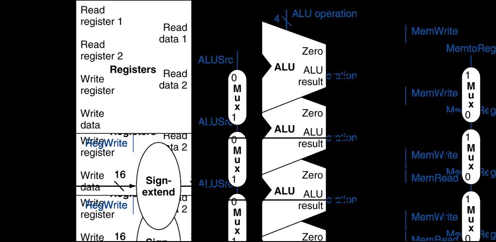
5 Multiplexers Can t just join wires together Use multiplexers Chapter 4 The Processor 5


6 Control Chapter 4 The Processor 6
7 Logic Design Basics Information encoded in binary Low voltage = 0, High voltage = 1 One wire per bit Multi-bit data encoded on multi-wire buses Combinational element Operate on data Output is a function of input State (sequential) elements Store information 4.2 Logic Design Conventions Chapter 4 The Processor 7
8 Combinational Elements AND-gate Y = A & B Adder Y = A + B A B + Y A B I0 I1 M u x S Y Multiplexer Y = S? I1 : I0 Y Arithmetic/Logic Unit Y = F(A, B) A ALU Y B F Chapter 4 The Processor 8
9 Sequential Elements Register: stores data in a circuit Uses a clock signal to determine when to update the stored value Edge-triggered: update when Clk changes from 0 to 1 D Clk Q Clk D Q Chapter 4 The Processor 9
10 Sequential Elements Register with write control Only updates on clock edge when write control input is 1 Used when stored value is required later Clk D Write Clk Q Write D Q Chapter 4 The Processor 10


11 Clocking Methodology Combinational logic transforms data during clock cycles Between clock edges Input from state elements, output to state element Longest delay determines clock period Chapter 4 The Processor 11
12 Building a Datapath Datapath Elements that process data and addresses in the CPU Registers, ALUs, mux s, memories, We will build a MIPS datapath incrementally Refining the overview design 4.3 Building a Datapath Chapter 4 The Processor 12

13 Instruction Fetch 32-bit register Increment by 4 for next instruction Chapter 4 The Processor 13

14 R-Format Instructions Read two register operands Perform arithmetic/logical operation Write register result Chapter 4 The Processor 14

15 Load/Store Instructions Read register operands Calculate address using 16-bit offset Use ALU, but sign-extend offset Load: Read memory and update register Store: Write register value to memory Chapter 4 The Processor 15
16 Branch Instructions Read register operands Compare operands Use ALU, subtract and check Zero output Calculate target address Sign-extend displacement Shift left 2 places (word displacement) Add to PC + 4 Already calculated by instruction fetch Chapter 4 The Processor 16


17 Branch Instructions Just re-routes wires Sign-bit wire replicated Chapter 4 The Processor 17
18 Composing the Elements First-cut data path does an instruction in one clock cycle Each datapath element can only do one function at a time Hence, we need separate instruction and data memories Use multiplexers where alternate data sources are used for different instructions Chapter 4 The Processor 18
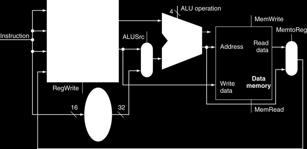
19 R-Type/Load/Store Datapath Chapter 4 The Processor 19


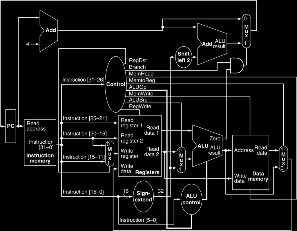
20 Full Datapath Chapter 4 The Processor 20
21 ALU Control ALU used for Load/Store: F = add Branch: F = subtract R-type: F depends on funct field ALU control Function 0000 AND 0001 OR 0010 add 0110 subtract 0111 set-on-less-than 1100 NOR 4.4 A Simple Implementation Scheme Chapter 4 The Processor 21
22 ALU Control Assume 2-bit ALUOp derived from opcode Combinational logic derives ALU control opcode ALUOp Operation funct ALU function ALU control lw 00 load word XXXXXX add 0010 sw 00 store word XXXXXX add 0010 beq 01 branch equal XXXXXX subtract 0110 R-type 10 add add 0010 subtract subtract 0110 AND AND 0000 OR OR 0001 set-on-less-than set-on-less-than 0111 Chapter 4 The Processor 22
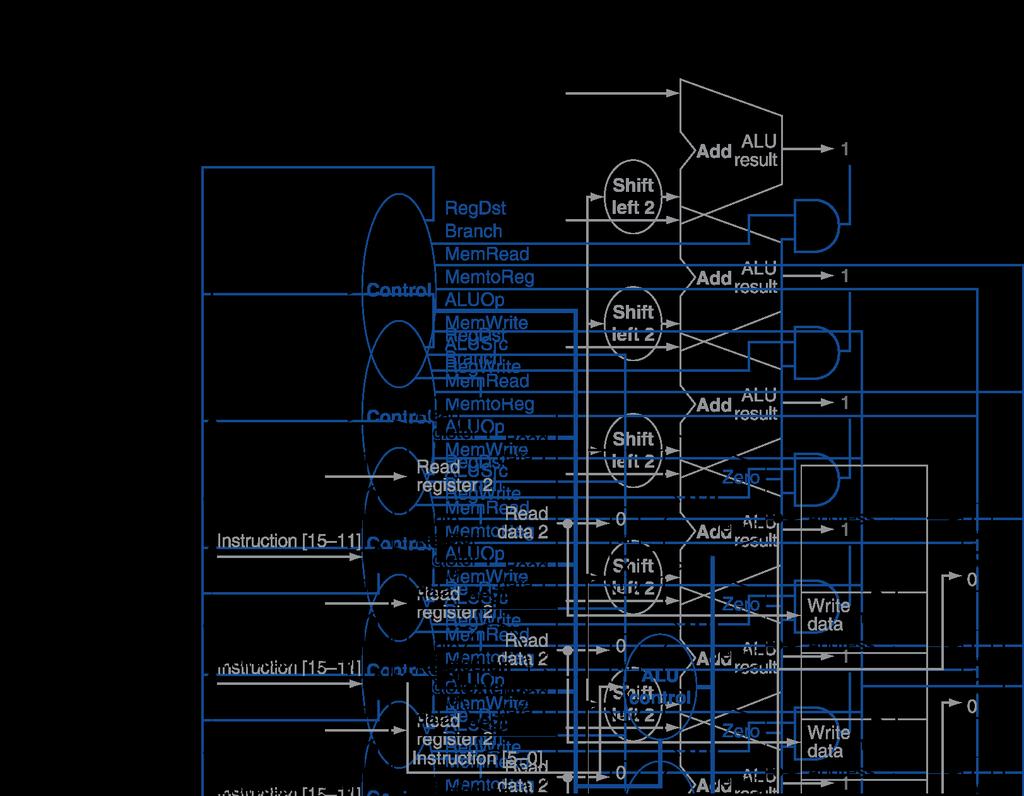
23 The Main Control Unit Control signals derived from instruction R-type Load/ Store Branch 0 rs rt rd shamt funct 31:26 25:21 20:16 15:11 10:6 5:0 35 or 43 rs rt address 31:26 25:21 20:16 15:0 4 rs rt address 31:26 25:21 20:16 15:0 opcode always read read, except for load write for R-type and load sign-extend and add Chapter 4 The Processor 23

24 Datapath With Control Chapter 4 The Processor 24
25 R-Type Instruction Chapter 4 The Processor 25
26 Load Instruction Chapter 4 The Processor 26

27 Branch-on-Equal Instruction Chapter 4 The Processor 27
28 Implementing Jumps Jump 2 address Jump uses word address Update PC with concatenation of Top 4 bits of old PC 26-bit jump address 00 31:26 25:0 Need an extra control signal decoded from opcode Chapter 4 The Processor 28


29 Datapath With Jumps Added Chapter 4 The Processor 29
30 Performance Issues Longest delay determines clock period Critical path: load instruction Instruction memory register file ALU data memory register file Not feasible to vary period for different instructions Violates design principle Making the common case fast We will improve performance by pipelining Chapter 4 The Processor 30

31 Pipelining Analogy Pipelined laundry: overlapping execution Parallelism improves performance Four loads: Speedup = 8/3.5 = 2.3 Non-stop: 4.5 An Overview of Pipelining Speedup = 2n/(0.5n + 1.5) n 4 = number of stages Chapter 4 The Processor 31
32 MIPS Pipeline Five stages, one step per stage 1. IF: Instruction fetch from memory 2. ID: Instruction decode & register read 3. EX: Execute operation or calculate address 4. MEM: Access memory operand 5. WB: Write result back to register Chapter 4 The Processor 32
33 Pipeline Performance Assume time for stages is 100ps for register read or write 200ps for other stages Compare pipelined datapath with single-cycle datapath Instr Instr fetch Register read ALU op Memory access Register write Total time lw 200ps 100 ps 200ps 200ps 100 ps 800ps sw 200ps 100 ps 200ps 200ps 700ps R-format 200ps 100 ps 200ps 100 ps 600ps beq 200ps 100 ps 200ps 500ps Chapter 4 The Processor 33
 Chapter 4 The Processor")
34 Pipeline Performance Single-cycle (T c = 800ps) Pipelined (T c = 200ps) Chapter 4 The Processor 34
35 Pipeline Speedup If all stages are balanced i.e., all take the same time Time between instructions pppppppppppppppppp = Time between instructions nnnnnnnnnnnnnnnnnnnnnnnn Number of stages If not balanced, speedup is less Speedup due to increased throughput Latency (time for each instruction) does not decrease Chapter 4 The Processor 35
36 Pipelining and ISA Design MIPS ISA designed for pipelining All instructions are 32-bits Easier to fetch and decode in one cycle c.f. x86: 1- to 17-byte instructions Few and regular instruction formats Can decode and read registers in one step Load/store addressing Can calculate address in 3 rd stage, access memory in 4 th stage Alignment of memory operands Memory access takes only one cycle Chapter 4 The Processor 36
37 Hazards Situations that prevent starting the next instruction in the next cycle Structure hazards A required resource is busy Data hazard Need to wait for previous instruction to complete its data read/write Control hazard Deciding on control action depends on previous instruction Chapter 4 The Processor 37
38 Structure Hazards Conflict for use of a resource In MIPS pipeline with a single memory Load/store requires data access Instruction fetch would have to stall for that cycle Would cause a pipeline bubble Hence, pipelined datapaths require separate instruction/data memories Or separate instruction/data caches Chapter 4 The Processor 38


39 Data Hazards An instruction depends on completion of data access by a previous instruction add $s0, $t0, $t1 sub $t2, $s0, $t3 Chapter 4 The Processor 39


40 Forwarding (aka Bypassing) Use result when it is computed Don t wait for it to be stored in a register Requires extra connections in the datapath Chapter 4 The Processor 40
41 Load-Use Data Hazard Can t always avoid stalls by forwarding If value not computed when needed Can t forward backward in time! Chapter 4 The Processor 42
42 Code Scheduling to Avoid Stalls Reorder code to avoid use of load result in the next instruction C code for A = B + E; C = B + F; stall stall lw $t1, 0($t0) lw $t2, 4($t0) add $t3, $t1, $t2 sw $t3, 12($t0) lw $t4, 8($t0) add $t5, $t1, $t4 sw $t5, 16($t0) 13 cycles Chapter 4 The Processor 43
43 Code Scheduling to Avoid Stalls Reorder code to avoid use of load result in the next instruction C code for A = B + E; C = B + F; stall stall lw $t1, 0($t0) lw $t2, 4($t0) add $t3, $t1, $t2 sw $t3, 12($t0) lw $t4, 8($t0) add $t5, $t1, $t4 sw $t5, 16($t0) 13 cycles lw $t1, 0($t0) lw $t2, 4($t0) lw $t4, 8($t0) add $t3, $t1, $t2 sw $t3, 12($t0) add $t5, $t1, $t4 sw $t5, 16($t0) 11 cycles Chapter 4 The Processor 44
44 Control Hazards Branch determines flow of control Fetching next instruction depends on branch outcome Pipeline can t always fetch correct instruction Still working on ID stage of branch In MIPS pipeline Need to compare registers and compute target early in the pipeline Add hardware to do it in ID stage Chapter 4 The Processor 45


45 Stall on Branch Wait until branch outcome determined before fetching next instruction Example (branch taken) ID stage performs comparison Chapter 4 The Processor 46
46 Branch Prediction Longer pipelines can t readily determine branch outcome early Stall penalty becomes unacceptable Predict outcome of branch Only stall if prediction is wrong In MIPS pipeline Can predict branches not taken Fetch instruction after branch, with no delay Chapter 4 The Processor 47

47 MIPS with Predict Not Taken Prediction correct Prediction incorrect Chapter 4 The Processor 48
48 More-Realistic Branch Prediction Static branch prediction Based on typical branch behavior Example: loop and if-statement branches Predict backward branches taken Predict forward branches not taken Dynamic branch prediction Hardware measures actual branch behavior e.g., record recent history of each branch Assume future behavior will continue the trend When wrong, stall while re-fetching, and update history Chapter 4 The Processor 49
49 Pipeline Summary The BIG Picture Pipelining improves performance by increasing instruction throughput Executes multiple instructions in parallel Each instruction has the same latency Subject to hazards Structure, data, control Instruction set design affects complexity of pipeline implementation Chapter 4 The Processor 50
50 MIPS Pipeline Five stages, one step per stage 1. IF: Instruction fetch from memory 2. ID: Instruction decode & register read 3. EX: Execute operation or calculate address 4. MEM: Access memory operand 5. WB: Write result back to register Chapter 4 The Processor 51


51 MIPS Pipelined Datapath 4.6 Pipelined Datapath and Control MEM Right-to-left flow leads to hazards WB Chapter 4 The Processor 52

52 Pipeline registers Need registers between stages To hold information produced in previous cycle Chapter 4 The Processor 53
53 Pipeline Operation Cycle-by-cycle flow of instructions through the pipelined datapath Single-clock-cycle pipeline diagram Shows pipeline usage in a single cycle Highlight resources used c.f. multi-clock-cycle pipeline diagram Graph of operation over time We ll look at single-clock-cycle diagrams for load & store Chapter 4 The Processor 54

54 IF for Load, Store, Instruction is read from memory using the address in PC and is placed in the IF/ID pipeline register PC address is incremented by 4 and then written back into PC to be ready for the next clock cycle This incremented address is also saved in IF/ID pipeline register in case it is needed later for an instruction Chapter 4 The Processor 55

55 ID for Load, Store, Instruction portion of IF/ID pipeline register supplying 16-bit immediate field, which is sign-extended to 32 bits, and the register numbers to read the two registers All three values are stored in the ID/EX pipeline register, along with incremented PC address Everything might be needed by any instruction during a later clock cycle is transferred Chapter 4 The Processor 56
56 EX for Load Load instruction reads Register 1 and Sign-extended immediate from the ID/EX pipeline register ALU adds them Sum is placed in the EX/MEM pipeline register Chapter 4 The Processor 57
57 MEM for Load Load instruction reads data memory using address from EX/MEM pipeline register Writes data into MEM/WB pipeline register Chapter 4 The Processor 58
58 WB for Load Reading data from MEM/WB pipeline register and writing it into register file Chapter 4 The Processor 59

59 WB for Load Reading data from MEM/WB pipeline register and writing it into register file Load must pass destination register number from ID/EX through EX/MEM to MEM/WB pipeline register for use in WB stage Wrong register number Chapter 4 The Processor 60

60 Corrected Datapath for Load Load must pass destination register number from ID/EX through EX/MEM to MEM/WB pipeline register for use in WB stage Chapter 4 The Processor 61
61 EX for Store Chapter 4 The Processor 62

62 MEM for Store Chapter 4 The Processor 63

63 WB for Store Chapter 4 The Processor 64

64 Multi-Cycle Pipeline Diagram Form showing resource usage Chapter 4 The Processor 65

65 Multi-Cycle Pipeline Diagram Traditional form Chapter 4 The Processor 66

66 Single-Cycle Pipeline Diagram State of pipeline in a given cycle Chapter 4 The Processor 67


67 Pipelined Control (Simplified) Chapter 4 The Processor 68

 used 3 cycles later Chapter 4 The")
68 Pipelined Control Control signals are derived from instruction As in single-cycle implementation Use a Main Control unit to generate signals during ID Stage Control signals for EX (ExtOp, ALUSrc, ) used 1 cycle later Control signals for Mem (MemWr, Branch) used 2 cycles later Control signals for WB (MemtoReg, MemWr) used 3 cycles later Chapter 4 The Processor 69
69 Assumptions for pipelining control signals Initial design motivated by single-cycle datapath control uses the same control signals Observe: No separate write signal for the PC as it is written every cycle No separate write signals for the pipeline registers (IF/ID, ID/EX, EX/MEM, MEM/WB), as they are written every cycle No separate read signal for instruction memory as it is read every clock cycle No separate read signal for register file as it is read every clock cycle Need to set control signals during each pipeline stage Since control signals are associated with components active during a single pipeline stage, can group control lines into five groups according to pipeline stage Will be modified by hazard detection unit!!
70 Implementing Pipeline Control RF/ID EX MEM WB RegDst RegDst IF/ID Register Main Control ALUSrc ALUOp RegDst MemWr Branch MemtoReg ID/Ex Register ALUSrc ALUOp MemRead MemWr Branch MemtoReg Ex/MEM Register MemRead MemWr Branch MemtoReg MEM/WB Register MemtoReg RegWr RegWr RegWr RegWr


71 Pipelined Control Chapter 4 The Processor 72


72 Pipelined Control Chapter 4 The Processor 73
73 Data Hazards in ALU Instructions Consider this sequence: sub $2, $1,$3 and $12,$2,$5 or $13,$6,$2 add $14,$2,$2 sw $15,100($2) We need 1. Detect the hazard 2. Resolve the hazard Stall Forwarding Mix 4.7 Data Hazards: Forwarding vs. Stalling We can resolve hazards with forwarding How do we detect when to forward? Chapter 4 The Processor 74
74 Dependencies & Forwarding Chapter 4 The Processor 75
75 Software Solution Have compiler guarantee never any data hazards! by rearranging instructions to insert independent instructions between instructions that would otherwise have a data hazard between them, or, if such rearrangement is not possible, insert nops sub $2, $1, $3 lw $10, 40($3) slt $5, $6, $7 and $12, $2, $5 or $13, $6, $2 add $14, $2, $2 sw $15, 100($2) or sub $2, $1, $3 nop nop and $12, $2, $5 or $13, $6, $2 add $14, $2, $2 sw $15, 100($2) Such compiler solutions may not always be possible, and nops slow the machine down MIPS: nop = no operation = 00 0 (32bits) = sll $0, $0, 0
76 Detecting the Need to Forward Forwarding to EX stage is studied Pass register numbers along pipeline e.g., ID/EX.RegisterRs = register number for Rs sitting in ID/EX pipeline register ALU operand register numbers in EX stage are given by ID/EX.RegisterRs, ID/EX.RegisterRt Data hazards when 1a. EX/MEM.RegisterRd = ID/EX.RegisterRs 1b. EX/MEM.RegisterRd = ID/EX.RegisterRt 2a. MEM/WB.RegisterRd = ID/EX.RegisterRs 2b. MEM/WB.RegisterRd = ID/EX.RegisterRt Fwd from EX/MEM pipeline reg Fwd from MEM/WB pipeline reg Chapter 4 The Processor 77
 Similar to above this time dependency between sub and or can be detected as MEM/WB.RegisterRd = ID/EX.")
77 Detecting the Need to Forward First hazard between sub $2, $1, $3 and and $12, $2, $5 is detected when and is in EX and sub is in MEM because EX/MEM.RegisterRd = ID/EX.RegisterRs = $2 (1a) Similar to above this time dependency between sub and or can be detected as MEM/WB.RegisterRd = ID/EX.RegisterRt = $2 (2b) Two dependencies between sub and add are not hazard Another form of forwarding but it occurs within reg file There is no hazard between sub and sw Chapter 4 The Processor 78
78 Detecting the Need to Forward But only if forwarding instruction will write to a register! EX/MEM.RegWrite, MEM/WB.RegWrite And only if Rd for that instruction is not $zero EX/MEM.RegisterRd 0, MEM/WB.RegisterRd 0 Chapter 4 The Processor 79


79 Forwarding Paths Chapter 4 The Processor 80
80 Forwarding Conditions EX hazard if (EX/MEM.RegWrite and (EX/MEM.RegisterRd 0) and (EX/MEM.RegisterRd = ID/EX.RegisterRs)) ForwardA = 10 if (EX/MEM.RegWrite and (EX/MEM.RegisterRd 0) and (EX/MEM.RegisterRd = ID/EX.RegisterRt)) ForwardB = 10 MEM hazard if (MEM/WB.RegWrite and (MEM/WB.RegisterRd 0) and (MEM/WB.RegisterRd = ID/EX.RegisterRs)) ForwardA = 01 if (MEM/WB.RegWrite and (MEM/WB.RegisterRd 0) and (MEM/WB.RegisterRd = ID/EX.RegisterRt)) ForwardB = 01 Chapter 4 The Processor 81
81 Forwarding Conditions EX hazard if (EX/MEM.RegWrite and (EX/MEM.RegisterRd 0) and (EX/MEM.RegisterRd = ID/EX.RegisterRs)) ForwardA = 10 if (EX/MEM.RegWrite and (EX/MEM.RegisterRd 0) and (EX/MEM.RegisterRd = ID/EX.RegisterRt)) ForwardB = 10 MEM hazard if (MEM/WB.RegWrite and (MEM/WB.RegisterRd 0) and (MEM/WB.RegisterRd = ID/EX.RegisterRs)) ForwardA = 01 if (MEM/WB.RegWrite and (MEM/WB.RegisterRd 0) and (MEM/WB.RegisterRd = ID/EX.RegisterRt)) ForwardB = 01 Forwards the result from the previous instr. to either input of the ALU Forwards the result from the second previous instr. to either input of the ALU Chapter 4 The Processor 82

82 Forwarding Paths One more 2:1 mux to select signed immediate as ALU input Chapter 4 The Processor 83
83 Double Data Hazard Consider the sequence: add $1,$1,$2 add $1,$1,$3 add $1,$1,$4 ALU IM Reg DM Reg ALU IM Reg DM Reg Reg $1 is written by both previous instructions (both hazards occur) But only the most recent result (from the second ADD) should be forwarded ALU IM Reg DM Reg Revise MEM hazard condition Only forward if EX hazard condition isn t true Chapter 4 The Processor 84
84 Double Data Hazard Consider the sequence: add $1,$1,$2 add $1,$1,$3 add $1,$1,$4 ALU IM Reg DM Reg ALU IM Reg DM Reg Reg $1 is written by both previous instructions (both hazards occur) But only the most recent result (from the second ADD) should be forwarded ALU IM Reg DM Reg Revise MEM hazard condition Only forward if EX hazard condition isn t true Chapter 4 The Processor 85
85 Revised Forwarding Condition MEM hazard if (MEM/WB.RegWrite and (MEM/WB.RegisterRd 0) Not forwarding from EX/MEM and not (EX/MEM.RegWrite and (EX/MEM.RegisterRd 0) and (EX/MEM.RegisterRd = ID/EX.RegisterRs)) and (MEM/WB.RegisterRd = ID/EX.RegisterRs)) ForwardA = 01 if (MEM/WB.RegWrite and (MEM/WB.RegisterRd 0) and not (EX/MEM.RegWrite and (EX/MEM.RegisterRd 0) and (EX/MEM.RegisterRd = ID/EX.RegisterRt)) and (MEM/WB.RegisterRd = ID/EX.RegisterRt)) ForwardB = 01 Chapter 4 The Processor 86
86 Datapath with Forwarding EX/MEM.RegWrite MEM/WB.RegWrite Chapter 4 The Processor 87


87 Datapath with Forwarding Called forwarding unit, not hazard detection unit, because once data is forwarded there is no hazard! EX/MEM.RegWrite MEM/WB.RegWrite Chapter 4 The Processor 88
88 Load-Use Data Hazard Forwarding is not the solution for all data hazard conditions Example: an instruction tries to read a register following a lw, that writes the same register Problem will occur lw $2, 20($1) and $4, $2, $5 or $8, $2, $6 add $9, $4, $2 slt $1, $6, $7 In addition to forwarding unit, we need hazard detection unit (HDU) to work during ID stage HDU will insert stall between the load and its use

89 Load-Use Data Hazard Need to stall for one cycle Chapter 4 The Processor 90
90 Load-Use Hazard Detection Unit Check when using instruction is decoded in ID stage ALU operand register numbers in ID stage are given by IF/ID.RegisterRs, IF/ID.RegisterRt Load-use hazard is detected when ID/EX.MemRead and ((ID/EX.RegisterRt = IF/ID.RegisterRs) or (ID/EX.RegisterRt = IF/ID.RegisterRt)) If detected, stall and insert bubble Chapter 4 The Processor 91
91 How to Stall the Pipeline Force control values in ID/EX register to 0 EX, MEM and WB do nop (no-operation) Prevent update of PC and IF/ID register Using (current) instruction is decoded again Following instruction is fetched again 1-cycle stall allows MEM to read data for lw Can subsequently forward to EX stage
 Chapter 4 The")
92 Stall/Bubble in the Pipeline Stall inserted here AND instruction is turned into NOP All instructions beginning with AND instruction are delayed one cycle Prevent update of PC and IF/ID register Hazard forces the AND and OR instructions to repeat in clock cycle 4, what they did in clock cycle 3 (AND reads regs and is decoded again OR is fetched again) Chapter 4 The Processor 93

93 Stall/Bubble in the Pipeline Or, more accurately Chapter 4 The Processor 94
94 Stall Hardware As a part of Hazard Unit, we have to implement Stall Hardware Prevent the instructions in the IF and ID stages from progressing down the pipeline Preventing PC and IF/ID pipeline register from changing Hazard Unit controls the writing of the PC (PC.write) and IF/ID (IF/ID.write) registers Insert a bubble between the lw instruction (in the EX stage) and the load-use instruction (in the ID stage) (i.e., insert a nop in the execution stream) Set the control bits in the EX, MEM, and WB control fields of the ID/EX pipeline register to 0 (nop). Hazard Unit controls the mux that chooses between the real control values and the 0 s Let the lw instruction and the instructions after it in the pipeline (before it in the code) proceed normally down the pipeline
95 Mechanics of Stalling What Stall Hardware does to stall the pipeline 1 cycle: Does not let IF/ID register change (disable write!) Instruction in ID stage repeats, (i.e., Stall) The instruction, just behind (in IF stage) must be stalled as well Hardware does not let PC change (disable write!) Instruction in IF stage repeats (i.e., Stall) Changes all the EX, MEM and WB control fields in ID/EX pipeline register to 0, Instruction just behind lw becomes a nop (a bubble is said to have been inserted into the pipeline) We cannot turn that instruction into nop by turning all bits in the instruction itself to 0 because it has already been decoded and control signals generated Recall nop = 00 0 (32 bits)


96 Datapath with Hazard Detection IF/ID.RegisterRs IF/ID.RegisterRt Chapter 4 The Processor 97
97 Stalling Execution example: lw $2, 20($1) and $4, $2, $5 or $4, $4, $2 add $9, $4, $2
98 Stalling Execution example: lw $2, 20($1) and $4, $2, $5 or $4, $4, $2 add $9, $4, $2 ID/EX.MemRead and ((ID/EX.RegisterRt = IF/ID.RegisterRs) or (ID/EX.RegisterRt = IF/ID.RegisterRt))
99 Stalling Execution example: lw $2, 20($1) and $4, $2, $5 or $4, $4, $2 add $9, $4, $2

100 Stalling Execution example: lw $2, 20($1) and $4, $2, $5 or $4, $4, $2 add $9, $4, $2
101 Stalling Execution example: lw $2, 20($1) and $4, $2, $5 or $4, $4, $2 add $9, $4, $2
102 Stalling Execution example: lw $2, 20($1) and $4, $2, $5 or $4, $4, $2 add $9, $4, $2
103 Stalls and Performance The BIG Picture Stalls reduce performance But are required to get correct results Compiler can arrange code to avoid hazards and stalls Requires knowledge of the pipeline structure Chapter 4 The Processor 104
104 Control Hazards When the flow of instruction addresses is not sequential (i.e., PC = PC + 4); incurred by change of flow instructions Conditional branches (beq, bne) Unconditional branches (j, jal, jr) Exceptions 105
105 Control Hazards When the flow of instruction addresses is not sequential (i.e., PC = PC + 4); incurred by change of flow instructions Conditional branches (beq, bne) Unconditional branches (j, jal, jr) Exceptions Possible hardware approaches Stall (impacts CPI) Move decision point as early in the pipeline as possible, thereby reducing the number of stall cycles Predict and hope for the best! 106
106 Control Hazards When the flow of instruction addresses is not sequential (i.e., PC = PC + 4); incurred by change of flow instructions Conditional branches (beq, bne) Unconditional branches (j, jal, jr) Exceptions Possible hardware approaches Stall (impacts CPI) Move decision point as early in the pipeline as possible, thereby reducing the number of stall cycles Predict and hope for the best! Possible software approaches Delay decision (requires compiler support) 107
107 Control Hazards When the flow of instruction addresses is not sequential (i.e., PC = PC + 4); incurred by change of flow instructions Conditional branches (beq, bne) Unconditional branches (j, jal, jr) Exceptions Possible hardware approaches Stall (impacts CPI) Move decision point as early in the pipeline as possible, thereby reducing the number of stall cycles Predict and hope for the best! Possible software approaches Delay decision (requires compiler support) Control hazards occur less frequently than data hazards, but there is nothing as effective against control hazards as forwarding is for data hazards 108
 PC Chapter 4 The")
108 Branch Hazards If branch outcome determined in MEM 1 st solution is to insert 3 stalls 4.8 Control Hazards Flush these instructions (Set control values to 0) PC Chapter 4 The Processor 109
109 How to Fix Control Hazard 2 nd solution is to put extra hardware in ID stage to Test (compare) registers Calculate branch (target) address, and Update PC That reduces the number of stalls to only 1 3 rd solution is to predict branch outcome For example: always predict branches are not taken When right, pipeline proceeds at full speed (no stall) When wrong, insert 1 stall Make sure nothing completes
110 Reducing Branch Delay Move hardware to determine outcome to ID stage Target address adder Register comparator Bitwise XOR registers and then NOR all results rather than using a subtractor and then test for zero Example: branch taken 36: sub $10, $4, $8 40: beq $1, $3, 7 44: and $12, $2, $5 48: or $13, $2, $6 52: add $14, $4, $2 56: slt $15, $6, $ : lw $4, 50($7) Branch taken Chapter 4 The Processor 111


111 Example: Branch Taken 36: sub $10, $4, $8 40: beq $1, $3, 7 44: and $12, $2, $5 48: or $13, $2, $6 52: add $14, $4, $2 56: slt $15, $6, $ : lw $4, 50($7) In Clock 3, stage ID detect beq and selects the top input of the mux feeding PC In Clock 3, stage ID stage sets control signal IF.Flush=1 Chapter 4 The Processor 112

 is inserted")
112 Example: Branch Taken 36: sub $10, $4, $8 40: beq $1, $3, 7 44: and $12, $2, $5 48: or $13, $2, $6 52: add $14, $4, $2 56: slt $15, $6, $ : lw $4, 50($7) In Clock 4, lw (from address 72) is fetched because in Clock 3, stage ID selected the top input of the mux feeding PC In Clock 4, a single bubble acting as a nop instruction (sll $0, $0, 0) is inserted into ID stage because control signal IF.Flush was set 1 in Clock 3 Chapter 4 The Processor 113
113 Data Hazards for Branches If a comparison register is a destination of 2 nd or 3 rd preceding ALU instruction add $1, $2, $3 IF ID EX MEM WB add $4, $5, $6 IF ID EX MEM WB IF ID EX MEM WB beq $1, $4, target IF ID EX MEM WB Can resolve using forwarding Chapter 4 The Processor 114
114 Data Hazards for Branches If a comparison register is a destination of preceding ALU instruction or 2 nd preceding load instruction Need 1 stall cycle lw $1, addr IF ID EX MEM WB add $4, $5, $6 IF ID EX MEM WB beq stalled IF ID beq $1, $4, target ID EX MEM WB Chapter 4 The Processor 115
115 Data Hazards for Branches If a comparison register is a destination of immediately preceding load instruction Need 2 stall cycles lw $1, addr IF ID EX MEM WB beq stalled IF ID beq stalled ID beq $1, $0, target ID EX MEM WB Chapter 4 The Processor 116
116 Branch Hazard - Prediction Assume branch is not taken If so, pipeline proceeds at full speed Fetch the next instruction in program order When the branch is resolved: If the branch is not taken, keep going, no problem If the branch is taken, we need to flush 3 instructions in the pipeline We use nop s to discard instructions in the IF, ID, EX stage. In the case of branches, we need to flush the instructions from the pipeline, so that they don't have any effect
117 Branch Hazard - Prediction branch is not taken branch is taken
118 Dynamic Branch Prediction In deeper and superscalar pipelines, branch penalty is more significant Use dynamic prediction Branch prediction buffer (aka branch history table) Indexed by recent branch instruction addresses Stores outcome (taken/not taken) To execute a branch Check table, expect the same outcome Start fetching from fall-through or target If wrong, flush pipeline and flip prediction Chapter 4 The Processor 119
119 Dynamic Branch Prediction A branch prediction buffer (aka branch history table or BHT) in the IF stage addressed by the lower bits of the PC, contains a bit passed to the ID stage through the IF/ID pipeline register that tells whether the branch was taken the last time it was execute
120 Dynamic Branch Prediction A branch prediction buffer (aka branch history table or BHT) in the IF stage addressed by the lower bits of the PC, contains a bit passed to the ID stage through the IF/ID pipeline register that tells whether the branch was taken the last time it was execute Prediction bit may predict incorrectly (may be a wrong prediction for this branch this iteration or may be from a different branch with the same low order PC bits) but the doesn t affect correctness, just performance Branch decision occurs in the ID stage after determining that the fetched instruction is a branch and checking the prediction bit
121 Dynamic Branch Prediction A branch prediction buffer (aka branch history table or BHT) in the IF stage addressed by the lower bits of the PC, contains a bit passed to the ID stage through the IF/ID pipeline register that tells whether the branch was taken the last time it was execute Prediction bit may predict incorrectly (may be a wrong prediction for this branch this iteration or may be from a different branch with the same low order PC bits) but the doesn t affect correctness, just performance Branch decision occurs in the ID stage after determining that the fetched instruction is a branch and checking the prediction bit If the prediction is wrong, flush the incorrect instruction(s) in pipeline, restart the pipeline with the right instruction, and invert the prediction bit A 4096 bit BHT varies from 1% misprediction to 18%
122 1-Bit Prediction Accuracy A 1-bit predictor will be incorrect twice when not taken Assume predict_bit = 0 to start (indicating branch not taken) and loop control is at the bottom of the loop code 1. First time through the loop, the predictor mispredicts the branch since the branch is taken back to the top of the loop; invert prediction bit (predict_bit = 1) 2. As long as branch is taken (looping), prediction is correct 3. Exiting the loop, the predictor again mispredicts the branch since this time the branch is not taken falling out of the loop; invert prediction bit (predict_bit = 0) Loop: 1 st loop instr 2 nd loop instr... last loop instr bne $1,$2,Loop fall out instr 123
123 1-Bit Prediction Accuracy A 1-bit predictor will be incorrect twice when not taken Assume predict_bit = 0 to start (indicating branch not taken) and loop control is at the bottom of the loop code 1. First time through the loop, the predictor mispredicts the branch since the branch is taken back to the top of the loop; invert prediction bit (predict_bit = 1) 2. As long as branch is taken (looping), prediction is correct Loop: 1 st loop instr 2 nd loop instr... last loop instr bne $1,$2,Loop fall out instr 3. Exiting the loop, the predictor again mispredicts the branch since this time the branch is not taken falling out of the loop; invert prediction bit (predict_bit = 0) For 10 times through the loop we have a 80% prediction accuracy for a branch that is taken 90% of the time 124


124 2-Bit Predictor Only change prediction on two successive mispredictions Gives 90% accuracy since a prediction must be wrong twice before the prediction bit is changed Chapter 4 The Processor 126
125 2-Bit Predictor A 2-bit scheme can give 90% accuracy since a prediction must be wrong twice before the prediction bit is changed 1 T Predict Taken NT T Predict Taken 1 Loop: 1 st loop instr 2 nd loop instr... last loop instr bne $1,$2,Loop fall out instr T NT Predict Not Taken 0 NT T NT 0 Predict Not Taken
126 2-Bit Predictor A 2-bit scheme can give 90% accuracy since a prediction must be wrong twice before the prediction bit is changed 1 T Predict Taken NT T Predict Taken 1 Loop: 1 st loop instr 2 nd loop instr... last loop instr bne $1,$2,Loop fall out instr T NT Predict Not Taken 0 NT T NT 0 Predict Not Taken
127 2-Bit Predictor A 2-bit scheme can give 90% accuracy since a prediction must be wrong twice before the prediction bit is changed 1 T Predict Taken Predict Not Taken 0 NT NT T right on 1 st iteration T NT Predict Taken T 1 NT 0 Predict Not Taken Loop: 1 st loop instr 2 nd loop instr... last loop instr bne $1,$2,Loop fall out instr
128 2-Bit Predictor A 2-bit scheme can give 90% accuracy since a prediction must be wrong twice before the prediction bit is changed right 9 times 1 T Predict Taken Predict Not Taken 0 NT NT T right on 1 st iteration T NT Predict Taken T 1 NT 0 Predict Not Taken Loop: 1 st loop instr 2 nd loop instr... last loop instr bne $1,$2,Loop fall out instr
129 2-Bit Predictor A 2-bit scheme can give 90% accuracy since a prediction must be wrong twice before the prediction bit is changed right 9 times 1 T Predict Taken Predict Not Taken 0 NT wrong on loop fall out NT T right on 1 st iteration T NT Predict Taken T 1 NT 0 Predict Not Taken Loop: 1 st loop instr 2 nd loop instr... last loop instr bne $1,$2,Loop fall out instr
130 Calculating the Branch Target If we predict the branch as taken, and suppose that is correct, what is the target address? Even with predictor, still need to calculate target address 1-cycle penalty for a taken branch Branch target buffer (BTB) Cache of target addresses The "value" in the cache is the address of the next instruction not the contents of the memory location Indexed by PC when instruction fetched If hit, and instruction is a branch that is predicted taken, MIPS can fetch target immediately from Inst. Memory Chapter 4 The Processor 132
131 Branch Target Buffer BTB is a cache that contains the predicted PC value for taken branches Is the current instruction a taken branch? BTB can provide the answer before current instruction is decoded and therefore enables fetching to begin after IF-stage What is the branch target? We need to know which address to fetch from ASAP, if we want to reduce stalls even further, ideally to 0 We must do this even before CPU knows the inst. is a branch BTB provides branch target for taken branches For not taken branches the target is simply PC+4 Chapter 4 The Processor 133
132 Branch Target Buffer Branch PC Predicted PC PC of instruction FETCH =? No: branch not predicted, proceed normally (Next PC = PC+4) Yes: instruction is branch and use predicted PC as next PC Chapter 4 The Processor 134
133 BTB Basic Operation IF stage sends PC to BTB BTB compares this value with the addresses (tags) in its cache If they match (hit), this means we must have executed the branch before Also we predict that the branch will do the same as the last time (taken) The associated value (target address) is sent from BTB to PC There is a chance that the address is not in BTB (miss) MIPS never executed that branch before (compulsory miss) MIPS did execute the branch before, but it was too long ago and it has been replaced by another branch in the BTB (capacity miss or conflict miss) It is not a branch instruction at all In either case, the branch cannot be predicted and the next value of PC will be PC+4 In ID stage, branch target is calculated anyway It is compared with the predicted PC If the prediction is correct, then there will be no stall If the prediction is wrong (or if the target address was not predicted because of BTB miss), one stall is inserted into the pipeline, PC is updated with correct value and BTB is updated accordingly Chapter 4 The Processor 135
134 BTB Basic Operation So there are 3 different situations: The branch is not in BTB Update PC with PC+4. When branch gets to ID stage, Stall pipeline if it is a taken branch instruction Calculate target address Update BTB Do not stall pipeline if it is not a taken branch or is a non-branch instruction The branch is in BTB and prediction is correct Update PC with target address When branch gets to ID stage, no action is taken (no stall) The branch is in BTB, but prediction (taken) is wrong Stall pipeline (kill target instruction already fetched) Update PC with PC + 4 Update BTB Chapter 4 The Processor 136

135 Branch Target Buffer Chapter 4 The Processor 137
136 Branch Delay Slot If no hardware branch predictor is used, MIPS compiler needs to stall pipeline for 1 cycle after every conditional branch using a nop instruction This nop instruction is always executed no matter the branch is taken or not Compiler may find a useful instruction instead of nop to fill the branch delay slot If it couldn t, nop still is the solution Chapter 4 The Processor 141


137 Branch Delay Slot branch instruction branch delay slot branch target (next instruction) (if branch taken) To make this approach effective, compiler needs to fill the branch delay slot by selecting an independent instruction from before the branch If no independent instruction is found compiler fills delay slot with a nop Disadvantages Branch delay can increase to multiple cycles in deeper pipelines and superscalar pipelines It is hard to find useful instructions to fill the slots Chapter 4 The Processor 142
138 Branch Delay Slot Chapter 4 The Processor 143
Chapter 4. The Processor
 Chapter 4 The Processor Introduction CPU performance factors Instruction count Determined by ISA and compiler CPI and Cycle time Determined by CPU hardware We will examine two MIPS implementations A simplified
COMPUTER ORGANIZATION AND DESIGN
 COMPUTER ORGANIZATION AND DESIGN 5 Edition th The Hardware/Software Interface Chapter 4 The Processor 4.1 Introduction Introduction CPU performance factors Instruction count CPI and Cycle time Determined
COMPUTER ORGANIZATION AND DESIGN The Hardware/Software Interface. 5 th. Edition. Chapter 4. The Processor
 COMPUTER ORGANIZATION AND DESIGN The Hardware/Software Interface 5 th Edition Chapter 4 The Processor Introduction CPU performance factors Instruction count Determined by ISA and compiler CPI and Cycle
Department of Computer and IT Engineering University of Kurdistan. Computer Architecture Pipelining. By: Dr. Alireza Abdollahpouri
 Department of Computer and IT Engineering University of Kurdistan Computer Architecture Pipelining By: Dr. Alireza Abdollahpouri Pipelined MIPS processor Any instruction set can be implemented in many
Chapter 4. The Processor
 Chapter 4 The Processor Introduction CPU performance factors Instruction count Determined by ISA and compiler CPI and Cycle time Determined by CPU hardware We will examine two MIPS implementations A simplified
Pipelining Analogy. Pipelined laundry: overlapping execution. Parallelism improves performance. Four loads: Non-stop: Speedup = 8/3.5 = 2.3.
 Pipelining Analogy Pipelined laundry: overlapping execution Parallelism improves performance Four loads: Speedup = 8/3.5 = 2.3 Non-stop: Speedup =2n/05n+15 2n/0.5n 1.5 4 = number of stages 4.5 An Overview
COMPUTER ORGANIZATION AND DESIGN. 5 th Edition. The Hardware/Software Interface. Chapter 4. The Processor
 COMPUTER ORGANIZATION AND DESIGN The Hardware/Software Interface 5 th Edition Chapter 4 The Processor Introduction CPU performance factors Instruction count Determined by ISA and compiler CPI and Cycle
Processor (II) - pipelining. Hwansoo Han
 - pipelining. Hwansoo Han") Processor (II) - pipelining Hwansoo Han Pipelining Analogy Pipelined laundry: overlapping execution Parallelism improves performance Four loads: Speedup = 8/3.5 =2.3 Non-stop: 2n/0.5n + 1.5 4 = number
Processor (II) - pipelining Hwansoo Han Pipelining Analogy Pipelined laundry: overlapping execution Parallelism improves performance Four loads: Speedup = 8/3.5 =2.3 Non-stop: 2n/0.5n + 1.5 4 = number
Full Datapath. Chapter 4 The Processor 2
 Pipelining Full Datapath Chapter 4 The Processor 2 Datapath With Control Chapter 4 The Processor 3 Performance Issues Longest delay determines clock period Critical path: load instruction Instruction memory
Full Datapath. Chapter 4 The Processor 2
 Pipelining Full Datapath Chapter 4 The Processor 2 Datapath With Control Chapter 4 The Processor 3 Performance Issues Longest delay determines clock period Critical path: load instruction Instruction memory
Chapter 4 The Processor 1. Chapter 4A. The Processor
 Chapter 4 The Processor 1 Chapter 4A The Processor Chapter 4 The Processor 2 Introduction CPU performance factors Instruction count Determined by ISA and compiler CPI and Cycle time Determined by CPU hardware
Chapter 4. Instruction Execution. Introduction. CPU Overview. Multiplexers. Chapter 4 The Processor 1. The Processor.
 COMPUTER ORGANIZATION AND DESIGN The Hardware/Software Interface 5 th Edition COMPUTER ORGANIZATION AND DESIGN The Hardware/Software Interface 5 th Edition Chapter 4 The Processor The Processor - Introduction
COMPUTER ORGANIZATION AND DESIGN. 5 th Edition. The Hardware/Software Interface. Chapter 4. The Processor
 COMPUTER ORGANIZATION AND DESIGN The Hardware/Software Interface 5 th Edition Chapter 4 The Processor COMPUTER ORGANIZATION AND DESIGN The Hardware/Software Interface 5 th Edition The Processor - Introduction
Chapter 4 The Processor 1. Chapter 4B. The Processor
 Chapter 4 The Processor 1 Chapter 4B The Processor Chapter 4 The Processor 2 Control Hazards Branch determines flow of control Fetching next instruction depends on branch outcome Pipeline can t always
LECTURE 3: THE PROCESSOR
 LECTURE 3: THE PROCESSOR Abridged version of Patterson & Hennessy (2013):Ch.4 Introduction CPU performance factors Instruction count Determined by ISA and compiler CPI and Cycle time Determined by CPU
Pipeline Hazards. Jin-Soo Kim Computer Systems Laboratory Sungkyunkwan University
 Pipeline Hazards Jin-Soo Kim (jinsookim@skku.edu) Computer Systems Laboratory Sungkyunkwan University http://csl.skku.edu Hazards What are hazards? Situations that prevent starting the next instruction
The Processor (3) Jinkyu Jeong Computer Systems Laboratory Sungkyunkwan University
 Jinkyu Jeong Computer Systems Laboratory Sungkyunkwan University") The Processor (3) Jinkyu Jeong (jinkyu@skku.edu) Computer Systems Laboratory Sungkyunkwan University http://csl.skku.edu EEE3050: Theory on Computer Architectures, Spring 2017, Jinkyu Jeong (jinkyu@skku.edu)
The Processor (3) Jinkyu Jeong (jinkyu@skku.edu) Computer Systems Laboratory Sungkyunkwan University http://csl.skku.edu EEE3050: Theory on Computer Architectures, Spring 2017, Jinkyu Jeong (jinkyu@skku.edu)
Lecture 3: The Processor (Chapter 4 of textbook) Chapter 4.1
 Chapter 4.1") Lecture 3: The Processor (Chapter 4 of textbook) Chapter 4.1 Introduction Chapter 4.1 Chapter 4.2 Review: MIPS (RISC) Design Principles Simplicity favors regularity fixed size instructions small number
Lecture 3: The Processor (Chapter 4 of textbook) Chapter 4.1 Introduction Chapter 4.1 Chapter 4.2 Review: MIPS (RISC) Design Principles Simplicity favors regularity fixed size instructions small number
The Processor. Z. Jerry Shi Department of Computer Science and Engineering University of Connecticut. CSE3666: Introduction to Computer Architecture
 The Processor Z. Jerry Shi Department of Computer Science and Engineering University of Connecticut CSE3666: Introduction to Computer Architecture Introduction CPU performance factors Instruction count
Chapter 4. The Processor
 Chapter 4 The Processor 1 Introduction CPU performance factors Instruction count Determined by ISA and compiler CPI and Cycle time Determined by CPU hardware We will examine two MIPS implementations A
Determined by ISA and compiler. We will examine two MIPS implementations. A simplified version A more realistic pipelined version
 MIPS Processor Introduction CPU performance factors Instruction count Determined by ISA and compiler CPI and Cycle time Determined by CPU hardware We will examine two MIPS implementations A simplified
CSEE 3827: Fundamentals of Computer Systems
 CSEE 3827: Fundamentals of Computer Systems Lecture 21 and 22 April 22 and 27, 2009 martha@cs.columbia.edu Amdahl s Law Be aware when optimizing... T = improved Taffected improvement factor + T unaffected
Computer Architecture Computer Science & Engineering. Chapter 4. The Processor BK TP.HCM
 Computer Architecture Computer Science & Engineering Chapter 4 The Processor Introduction CPU performance factors Instruction count Determined by ISA and compiler CPI and Cycle time Determined by CPU hardware
Chapter 4. The Processor
 Chapter 4 The Processor Introduction CPU performance factors Instruction count Determined by ISA and compiler CPI and Cycle time Determined by CPU hardware 4.1 Introduction We will examine two MIPS implementations
Chapter 4. The Processor
 Chapter 4 The Processor Introduction CPU performance factors Instruction count Determined by ISA and compiler CPI and Cycle time Determined by CPU hardware We will examine two MIPS implementations A simplified
Chapter 4. The Processor
 Chapter 4 The Processor 4.1 Introduction Introduction CPU performance factors Instruction count CPI and Cycle time Determined by CPU hardware We will examine two MIPS implementations Determined by ISA
EIE/ENE 334 Microprocessors
 EIE/ENE 334 Microprocessors Lecture 6: The Processor Week #06/07 : Dejwoot KHAWPARISUTH Adapted from Computer Organization and Design, 4 th Edition, Patterson & Hennessy, 2009, Elsevier (MK) http://webstaff.kmutt.ac.th/~dejwoot.kha/
Chapter 4. The Processor
 Chapter 4 The Processor Introduction CPU performance factors Instruction count Determined by ISA and compiler CPI and Cycle time Determined by CPU hardware We will examine two MIPS implementations A simplified
Thomas Polzer Institut für Technische Informatik
 Thomas Polzer tpolzer@ecs.tuwien.ac.at Institut für Technische Informatik Pipelined laundry: overlapping execution Parallelism improves performance Four loads: Speedup = 8/3.5 = 2.3 Non-stop: Speedup =
Computer Organization and Structure. Bing-Yu Chen National Taiwan University
 Computer Organization and Structure Bing-Yu Chen National Taiwan University The Processor Logic Design Conventions Building a Datapath A Simple Implementation Scheme An Overview of Pipelining Pipelined
Processor (I) - datapath & control. Hwansoo Han
 - datapath & control. Hwansoo Han") Processor (I) - datapath & control Hwansoo Han Introduction CPU performance factors Instruction count - Determined by ISA and compiler CPI and Cycle time - Determined by CPU hardware We will examine two
Processor (I) - datapath & control Hwansoo Han Introduction CPU performance factors Instruction count - Determined by ISA and compiler CPI and Cycle time - Determined by CPU hardware We will examine two
Computer Architecture Computer Science & Engineering. Chapter 4. The Processor BK TP.HCM
 Computer Architecture Computer Science & Engineering Chapter 4 The Processor Introduction CPU performance factors Instruction count Determined by ISA and compiler CPI and Cycle time Determined by CPU hardware
3/12/2014. Single Cycle (Review) CSE 2021: Computer Organization. Single Cycle with Jump. Multi-Cycle Implementation. Why Multi-Cycle?
 CSE 2021: Computer Organization. Single Cycle with Jump. Multi-Cycle Implementation. Why Multi-Cycle?") CSE 2021: Computer Organization Single Cycle (Review) Lecture-10b CPU Design : Pipelining-1 Overview, Datapath and control Shakil M. Khan 2 Single Cycle with Jump Multi-Cycle Implementation Instruction:
CSE 2021: Computer Organization Single Cycle (Review) Lecture-10b CPU Design : Pipelining-1 Overview, Datapath and control Shakil M. Khan 2 Single Cycle with Jump Multi-Cycle Implementation Instruction:
Lecture Topics. Announcements. Today: Data and Control Hazards (P&H ) Next: continued. Exam #1 returned. Milestone #5 (due 2/27)
 Next: continued. Exam #1 returned. Milestone #5 (due 2/27)") Lecture Topics Today: Data and Control Hazards (P&H 4.7-4.8) Next: continued 1 Announcements Exam #1 returned Milestone #5 (due 2/27) Milestone #6 (due 3/13) 2 1 Review: Pipelined Implementations Pipelining
Lecture Topics Today: Data and Control Hazards (P&H 4.7-4.8) Next: continued 1 Announcements Exam #1 returned Milestone #5 (due 2/27) Milestone #6 (due 3/13) 2 1 Review: Pipelined Implementations Pipelining
The Processor: Datapath and Control. Jin-Soo Kim Computer Systems Laboratory Sungkyunkwan University
 The Processor: Datapath and Control Jin-Soo Kim (jinsookim@skku.edu) Computer Systems Laboratory Sungkyunkwan University http://csl.skku.edu Introduction CPU performance factors Instruction count Determined
COMPUTER ORGANIZATION AND DESIGN
 ARM COMPUTER ORGANIZATION AND DESIGN Edition The Hardware/Software Interface Chapter 4 The Processor Modified and extended by R.J. Leduc - 2016 To understand this chapter, you will need to understand some
COMPUTER ORGANIZATION AND DESIGN. The Hardware/Software Interface. Chapter 4. The Processor: A Based on P&H
 COMPUTER ORGANIZATION AND DESIGN The Hardware/Software Interface Chapter 4 The Processor: A Based on P&H Introduction We will examine two MIPS implementations A simplified version A more realistic pipelined
Pipelining. CSC Friday, November 6, 2015
 Pipelining CSC 211.01 Friday, November 6, 2015 Performance Issues Longest delay determines clock period Critical path: load instruction Instruction memory register file ALU data memory register file Not
CENG 3420 Lecture 06: Pipeline
 CENG 3420 Lecture 06: Pipeline Bei Yu byu@cse.cuhk.edu.hk CENG3420 L06.1 Spring 2019 Outline q Pipeline Motivations q Pipeline Hazards q Exceptions q Background: Flip-Flop Control Signals CENG3420 L06.2
The Processor (1) Jinkyu Jeong Computer Systems Laboratory Sungkyunkwan University
 Jinkyu Jeong Computer Systems Laboratory Sungkyunkwan University") The Processor (1) Jinkyu Jeong (jinkyu@skku.edu) Computer Systems Laboratory Sungkyunkwan University http://csl.skku.edu EEE3050: Theory on Computer Architectures, Spring 2017, Jinkyu Jeong (jinkyu@skku.edu)
The Processor (1) Jinkyu Jeong (jinkyu@skku.edu) Computer Systems Laboratory Sungkyunkwan University http://csl.skku.edu EEE3050: Theory on Computer Architectures, Spring 2017, Jinkyu Jeong (jinkyu@skku.edu)
Chapter 4. The Processor Designing the datapath
 Chapter 4 The Processor Designing the datapath Introduction CPU performance determined by Instruction Count Clock Cycles per Instruction (CPI) and Cycle time Determined by Instruction Set Architecure (ISA)
Chapter 4. The Processor. Instruction count Determined by ISA and compiler. We will examine two MIPS implementations
 Chapter 4 The Processor Part I Introduction CPU performance factors Instruction count Determined by ISA and compiler CPI and Cycle time Determined by CPU hardware We will examine two MIPS implementations
Outline Marquette University
 COEN-4710 Computer Hardware Lecture 4 Processor Part 2: Pipelining (Ch.4) Cristinel Ababei Department of Electrical and Computer Engineering Credits: Slides adapted primarily from presentations from Mike
ECE260: Fundamentals of Computer Engineering
 Data Hazards in a Pipelined Datapath James Moscola Dept. of Engineering & Computer Science York College of Pennsylvania Based on Computer Organization and Design, 5th Edition by Patterson & Hennessy Data
Chapter 4. The Processor
 Chapter 4 The Processor Recall. ISA? Instruction Fetch Instruction Decode Operand Fetch Execute Result Store Next Instruction Instruction Format or Encoding how is it decoded? Location of operands and
COMPUTER ORGANIZATION AND DESIGN The Hardware/Software Interface 5 th Edition. Chapter 4. The Processor
 COMPUTER ORGANIZATION AND DESIGN The Hardware/Software Interface 5 th Edition Chapter 4 The Processor The Processor? Chapter 4 The Processor 2 Introduction We will learn How the ISA determines many aspects
Chapter 4. The Processor. Jiang Jiang
 Chapter 4 The Processor Jiang Jiang jiangjiang@ic.sjtu.edu.cn [Adapted from Computer Organization and Design, 4 th Edition, Patterson & Hennessy, 2008, MK] Chapter 4 The Processor 2 Introduction CPU performance
MIPS Pipelining. Computer Organization Architectures for Embedded Computing. Wednesday 8 October 14
 MIPS Pipelining Computer Organization Architectures for Embedded Computing Wednesday 8 October 14 Many slides adapted from: Computer Organization and Design, Patterson & Hennessy 4th Edition, 2011, MK
COMPUTER ORGANIZATION AND DESI
 COMPUTER ORGANIZATION AND DESIGN 5 Edition th The Hardware/Software Interface Chapter 4 The Processor 4.1 Introduction Introduction CPU performance factors Instruction count Determined by ISA and compiler
Chapter 4. The Processor. Computer Architecture and IC Design Lab
 Chapter 4 The Processor Introduction CPU performance factors CPI Clock Cycle Time Instruction count Determined by ISA and compiler CPI and Cycle time Determined by CPU hardware We will examine two MIPS
Systems Architecture
 Systems Architecture Lecture 15: A Simple Implementation of MIPS Jeremy R. Johnson Anatole D. Ruslanov William M. Mongan Some or all figures from Computer Organization and Design: The Hardware/Software
14:332:331 Pipelined Datapath
 14:332:331 Pipelined Datapath I n s t r. O r d e r Inst 0 Inst 1 Inst 2 Inst 3 Inst 4 Single Cycle Disadvantages & Advantages Uses the clock cycle inefficiently the clock cycle must be timed to accommodate
zhandling Data Hazards The objectives of this module are to discuss how data hazards are handled in general and also in the MIPS architecture.
 zhandling Data Hazards The objectives of this module are to discuss how data hazards are handled in general and also in the MIPS architecture. We have already discussed in the previous module that true
Outline. A pipelined datapath Pipelined control Data hazards and forwarding Data hazards and stalls Branch (control) hazards Exception
 hazards Exception") Outline A pipelined datapath Pipelined control Data hazards and forwarding Data hazards and stalls Branch (control) hazards Exception 1 4 Which stage is the branch decision made? Case 1: 0 M u x 1 Add
Outline A pipelined datapath Pipelined control Data hazards and forwarding Data hazards and stalls Branch (control) hazards Exception 1 4 Which stage is the branch decision made? Case 1: 0 M u x 1 Add
Pipelined Datapath. Reading. Sections Practice Problems: 1, 3, 8, 12 (2) Lecture notes from MKP, H. H. Lee and S.
 Lecture notes from MKP, H. H. Lee and S.") Pipelined Datapath Lecture notes from KP, H. H. Lee and S. Yalamanchili Sections 4.5 4. Practice Problems:, 3, 8, 2 ing (2) Pipeline Performance Assume time for stages is ps for register read or write
Pipelined Datapath Lecture notes from KP, H. H. Lee and S. Yalamanchili Sections 4.5 4. Practice Problems:, 3, 8, 2 ing (2) Pipeline Performance Assume time for stages is ps for register read or write
Chapter 4 (Part II) Sequential Laundry
 Sequential Laundry") Chapter 4 (Part II) The Processor Baback Izadi Division of Engineering Programs bai@engr.newpaltz.edu Sequential Laundry 6 P 7 8 9 10 11 12 1 2 A T a s k O r d e r A B C D 30 30 30 30 30 30 30 30 30 30
Chapter 4 (Part II) The Processor Baback Izadi Division of Engineering Programs bai@engr.newpaltz.edu Sequential Laundry 6 P 7 8 9 10 11 12 1 2 A T a s k O r d e r A B C D 30 30 30 30 30 30 30 30 30 30
Pipelined Datapath. Reading. Sections Practice Problems: 1, 3, 8, 12
 Pipelined Datapath Lecture notes from KP, H. H. Lee and S. Yalamanchili Sections 4.5 4. Practice Problems:, 3, 8, 2 ing Note: Appendices A-E in the hardcopy text correspond to chapters 7- in the online
4. The Processor Computer Architecture COMP SCI 2GA3 / SFWR ENG 2GA3. Emil Sekerinski, McMaster University, Fall Term 2015/16
 4. The Processor Computer Architecture COMP SCI 2GA3 / SFWR ENG 2GA3 Emil Sekerinski, McMaster University, Fall Term 2015/16 Instruction Execution Consider simplified MIPS: lw/sw rt, offset(rs) add/sub/and/or/slt
1 Hazards COMP2611 Fall 2015 Pipelined Processor
 1 Hazards Dependences in Programs 2 Data dependence Example: lw $1, 200($2) add $3, $4, $1 add can t do ID (i.e., read register $1) until lw updates $1 Control dependence Example: bne $1, $2, target add
Pipelined datapath Staging data. CS2504, Spring'2007 Dimitris Nikolopoulos
 Pipelined datapath Staging data b 55 Life of a load in the MIPS pipeline Note: both the instruction and the incremented PC value need to be forwarded in the next stage (in case the instruction is a beq)
EE557--FALL 1999 MIDTERM 1. Closed books, closed notes
 NAME: SOLUTIONS STUDENT NUMBER: EE557--FALL 1999 MIDTERM 1 Closed books, closed notes GRADING POLICY: The front page of your exam shows your total numerical score out of 75. The highest numerical score
Lecture 9 Pipeline and Cache
 Lecture 9 Pipeline and Cache Peng Liu liupeng@zju.edu.cn 1 What makes it easy Pipelining Review all instructions are the same length just a few instruction formats memory operands appear only in loads
LECTURE 9. Pipeline Hazards
 LECTURE 9 Pipeline Hazards PIPELINED DATAPATH AND CONTROL In the previous lecture, we finalized the pipelined datapath for instruction sequences which do not include hazards of any kind. Remember that
The Processor: Improving the performance - Control Hazards
 The Processor: Improving the performance - Control Hazards Wednesday 14 October 15 Many slides adapted from: and Design, Patterson & Hennessy 5th Edition, 2014, MK and from Prof. Mary Jane Irwin, PSU Summary
DEE 1053 Computer Organization Lecture 6: Pipelining
 Dept. Electronics Engineering, National Chiao Tung University DEE 1053 Computer Organization Lecture 6: Pipelining Dr. Tian-Sheuan Chang tschang@twins.ee.nctu.edu.tw Dept. Electronics Engineering National
Lecture 9. Pipeline Hazards. Christos Kozyrakis Stanford University
 Lecture 9 Pipeline Hazards Christos Kozyrakis Stanford University http://eeclass.stanford.edu/ee18b 1 Announcements PA-1 is due today Electronic submission Lab2 is due on Tuesday 2/13 th Quiz1 grades will
ECE473 Computer Architecture and Organization. Pipeline: Data Hazards
 Computer Architecture and Organization Pipeline: Data Hazards Lecturer: Prof. Yifeng Zhu Fall, 2015 Portions of these slides are derived from: Dave Patterson UCB Lec 14.1 Pipelining Outline Introduction
ECE232: Hardware Organization and Design
 ECE232: Hardware Organization and Design Lecture 14: One Cycle MIPs Datapath Adapted from Computer Organization and Design, Patterson & Hennessy, UCB R-Format Instructions Read two register operands Perform
CS 251, Winter 2018, Assignment % of course mark
 CS 251, Winter 2018, Assignment 5.0.4 3% of course mark Due Wednesday, March 21st, 4:30PM Lates accepted until 10:00am March 22nd with a 15% penalty 1. (10 points) The code sequence below executes on a
5 th Edition. The Processor We will examine two MIPS implementations A simplified version A more realistic pipelined version
 COMPUTER ORGANIZATION AND DESIGN The Hardware/Software Interface Chapter 4 5 th Edition Introduction CPU performance factors Instruction count Determined by ISA and compiler CPI and Cycle time Determined
ELE 655 Microprocessor System Design
 ELE 655 Microprocessor System Design Section 2 Instruction Level Parallelism Class 1 Basic Pipeline Notes: Reg shows up two places but actually is the same register file Writes occur on the second half
Computer and Information Sciences College / Computer Science Department Enhancing Performance with Pipelining
 Computer and Information Sciences College / Computer Science Department Enhancing Performance with Pipelining Single-Cycle Design Problems Assuming fixed-period clock every instruction datapath uses one
ECE260: Fundamentals of Computer Engineering
 Datapath for a Simplified Processor James Moscola Dept. of Engineering & Computer Science York College of Pennsylvania Based on Computer Organization and Design, 5th Edition by Patterson & Hennessy Introduction
Lecture 7 Pipelining. Peng Liu.
 Lecture 7 Pipelining Peng Liu liupeng@zju.edu.cn 1 Review: The Single Cycle Processor 2 Review: Given Datapath,RTL -> Control Instruction Inst Memory Adr Op Fun Rt
Computer Organization and Structure
 Computer Organization and Structure 1. Assuming the following repeating pattern (e.g., in a loop) of branch outcomes: Branch outcomes a. T, T, NT, T b. T, T, T, NT, NT Homework #4 Due: 2014/12/9 a. What
COMPUTER ORGANIZATION AND DESIGN. 5 th Edition. The Hardware/Software Interface. Chapter 4. The Processor
 COMPUTER ORGANIZATION AND DESIGN The Hardware/Software Interface 5 th Edition Chapter 4 The Processor Introduction CPU performance factors Instruction count Determined by ISA and compiler CPI and Cycle
Pipelining. Ideal speedup is number of stages in the pipeline. Do we achieve this? 2. Improve performance by increasing instruction throughput ...
 CHAPTER 6 1 Pipelining Instruction class Instruction memory ister read ALU Data memory ister write Total (in ps) Load word 200 100 200 200 100 800 Store word 200 100 200 200 700 R-format 200 100 200 100
Design a MIPS Processor (2/2)
") 93-2Digital System Design Design a MIPS Processor (2/2) Lecturer: Chihhao Chao Advisor: Prof. An-Yeu Wu 2005/5/13 Friday ACCESS IC LABORTORY Outline v 6.1 An Overview of Pipelining v 6.2 A Pipelined Datapath
93-2Digital System Design Design a MIPS Processor (2/2) Lecturer: Chihhao Chao Advisor: Prof. An-Yeu Wu 2005/5/13 Friday ACCESS IC LABORTORY Outline v 6.1 An Overview of Pipelining v 6.2 A Pipelined Datapath
Full Datapath. CSCI 402: Computer Architectures. The Processor (2) 3/21/19. Fengguang Song Department of Computer & Information Science IUPUI
 3/21/19. Fengguang Song Department of Computer & Information Science IUPUI") CSCI 42: Computer Architectures The Processor (2) Fengguang Song Department of Computer & Information Science IUPUI Full Datapath Branch Target Instruction Fetch Immediate 4 Today s Contents We have looked
CSCI 42: Computer Architectures The Processor (2) Fengguang Song Department of Computer & Information Science IUPUI Full Datapath Branch Target Instruction Fetch Immediate 4 Today s Contents We have looked
TDT4255 Computer Design. Lecture 4. Magnus Jahre. TDT4255 Computer Design
 1 TDT4255 Computer Design Lecture 4 Magnus Jahre 2 Outline Chapter 4.1 to 4.4 A Multi-cycle Processor Appendix D 3 Chapter 4 The Processor Acknowledgement: Slides are adapted from Morgan Kaufmann companion
CSCI 402: Computer Architectures. Fengguang Song Department of Computer & Information Science IUPUI. Today s Content
 3/6/8 CSCI 42: Computer Architectures The Processor (2) Fengguang Song Department of Computer & Information Science IUPUI Today s Content We have looked at how to design a Data Path. 4.4, 4.5 We will design
ECE260: Fundamentals of Computer Engineering
 Pipelining James Moscola Dept. of Engineering & Computer Science York College of Pennsylvania Based on Computer Organization and Design, 5th Edition by Patterson & Hennessy What is Pipelining? Pipelining
Lecture 2: Processor and Pipelining 1
 The Simple BIG Picture! Chapter 3 Additional Slides The Processor and Pipelining CENG 6332 2 Datapath vs Control Datapath signals Control Points Controller Datapath: Storage, FU, interconnect sufficient
Introduction. Datapath Basics
 Introduction CPU performance factors - Instruction count; determined by ISA and compiler - CPI and Cycle time; determined by CPU hardware 1 We will examine a simplified MIPS implementation in this course
COSC121: Computer Systems. ISA and Performance
 COSC121: Computer Systems. ISA and Performance Jeremy Bolton, PhD Assistant Teaching Professor Constructed using materials: - Patt and Patel Introduction to Computing Systems (2nd) - Patterson and Hennessy
ECS 154B Computer Architecture II Spring 2009
 ECS 154B Computer Architecture II Spring 2009 Pipelining Datapath and Control 6.2-6.3 Partially adapted from slides by Mary Jane Irwin, Penn State And Kurtis Kredo, UCD Pipelined CPU Break execution into
CS 251, Winter 2019, Assignment % of course mark
 CS 251, Winter 2019, Assignment 5.1.1 3% of course mark Due Wednesday, March 27th, 5:30PM Lates accepted until 1:00pm March 28th with a 15% penalty 1. (10 points) The code sequence below executes on a
Improving Performance: Pipelining
 Improving Performance: Pipelining Memory General registers Memory ID EXE MEM WB Instruction Fetch (includes PC increment) ID Instruction Decode + fetching values from general purpose registers EXE EXEcute
ECE331: Hardware Organization and Design
 ECE331: Hardware Organization and Design Lecture 27: Midterm2 review Adapted from Computer Organization and Design, Patterson & Hennessy, UCB Midterm 2 Review Midterm will cover Section 1.6: Processor
COMP2611: Computer Organization. The Pipelined Processor
 COMP2611: Computer Organization The 1 2 Background 2 High-Performance Processors 3 Two techniques for designing high-performance processors by exploiting parallelism: Multiprocessing: parallelism among
The MIPS Processor Datapath
 The MIPS Processor Datapath Module Outline MIPS datapath implementation Register File, Instruction memory, Data memory Instruction interpretation and execution. Combinational control Assignment: Datapath
Data Hazards Compiler Scheduling Pipeline scheduling or instruction scheduling: Compiler generates code to eliminate hazard
 Data Hazards Compiler Scheduling Pipeline scheduling or instruction scheduling: Compiler generates code to eliminate hazard Consider: a = b + c; d = e - f; Assume loads have a latency of one clock cycle:
EE557--FALL 1999 MAKE-UP MIDTERM 1. Closed books, closed notes
 NAME: STUDENT NUMBER: EE557--FALL 1999 MAKE-UP MIDTERM 1 Closed books, closed notes Q1: /1 Q2: /1 Q3: /1 Q4: /1 Q5: /15 Q6: /1 TOTAL: /65 Grade: /25 1 QUESTION 1(Performance evaluation) 1 points We are
Pipeline design. Mehran Rezaei
 Pipeline design Mehran Rezaei How Can We Improve the Performance? Exec Time = IC * CPI * CCT Optimization IC CPI CCT Source Level * Compiler * * ISA * * Organization * * Technology * With Pipelining We
Single Cycle Datapath
 Single Cycle atapath Lecture notes from MKP, H. H. Lee and S. Yalamanchili Section 4.-4.4 Appendices B.7, B.8, B.,.2 Practice Problems:, 4, 6, 9 ing (2) Introduction We will examine two MIPS implementations
Control Hazards - branching causes problems since the pipeline can be filled with the wrong instructions.
 Control Hazards - branching causes problems since the pipeline can be filled with the wrong instructions Stage Instruction Fetch Instruction Decode Execution / Effective addr Memory access Write-back Abbreviation
CS 61C: Great Ideas in Computer Architecture Pipelining and Hazards
 CS 61C: Great Ideas in Computer Architecture Pipelining and Hazards Instructors: Vladimir Stojanovic and Nicholas Weaver http://inst.eecs.berkeley.edu/~cs61c/sp16 1 Pipelined Execution Representation Time
ECE232: Hardware Organization and Design
 ECE232: Hardware Organization and Design Lecture 17: Pipelining Wrapup Adapted from Computer Organization and Design, Patterson & Hennessy, UCB Outline The textbook includes lots of information Focus on
COSC 6385 Computer Architecture - Pipelining
 COSC 6385 Computer Architecture - Pipelining Fall 2006 Some of the slides are based on a lecture by David Culler, Instruction Set Architecture Relevant features for distinguishing ISA s Internal storage
CS 110 Computer Architecture. Pipelining. Guest Lecture: Shu Yin. School of Information Science and Technology SIST
 CS 110 Computer Architecture Pipelining Guest Lecture: Shu Yin http://shtech.org/courses/ca/ School of Information Science and Technology SIST ShanghaiTech University Slides based on UC Berkley's CS61C