UART. ELEC 418 Advanced Digital Systems Dr. Ron Hayne. Images Courtesy of Cengage Learning
|
|
|
- Irma Hensley
- 6 years ago
- Views:
Transcription

1 UART ELEC 418 Advanced Digital Systems Dr. Ron Hayne Images Courtesy of Cengage Learning
2 UART Universal Asynchronous Receiver Transmitter Serial Data Transmission
3 68HC11 Microcontroller UART Registers RSR Receive Shift Register RDR Receive Data Register TDR Transmit Data Register TSR Transmit Shift Register SCCR Serial Communications Control Register SCSR Serial Communications Status Register UART Flags TDRE Transmit Data Register Empty RDRF Receive Data Register Full
4 UART Block Diagram
5 Transmitter Operation Microcontroller waits until TDRE = '1' Loads data into TDR Clears TDRE UART transfers data from TDR to TSR Sets TDRE UART outputs start bit ('0') then shifts TSR right eight times followed by a stop bit ('1')
6 Transmitter SM Chart
7 Transmitter VHDL Model library IEEE; use IEEE.std_logic_1164.all; use IEEE.numeric_std.all; entity UART_Transmitter is port(bclk, sysclk, rst_b, TDRE, loadtdr: in std_logic; DBUS: in unsigned(7 downto 0); settdre, TxD: out std_logic); end UART_Transmitter;
8 Transmitter VHDL Model architecture xmit of UART_Transmitter is type statetype is (IDLE, SYNCH, TDATA); signal state, nextstate: statetype; signal TSR: unsigned(8 downto 0); signal TDR: unsigned(7 downto 0); signal Bct: integer range 0 to 9; signal inc, clr, loadtsr, shfttsr, start: std_logic; signal Bclk_rising, Bclk_Dlayed: std_logic; begin TxD <= TSR(0); settdre <= loadtsr; Bclk_rising <= Bclk and (not Bclk_Dlayed);
9 Transmitter VHDL Model Xmit_Control: process(state, TDRE, Bct, Bclk_rising) begin inc <= '0'; clr <= '0'; loadtsr <= '0'; shfttsr <= '0'; start <= '0'; case state is when IDLE => if (TDRE = '0') then loadtsr <= '1'; nextstate <= SYNCH; else nextstate <= IDLE; end if;
10 Transmitter VHDL Model when SYNCH => if (Bclk_rising = '1') then start <= '1'; nextstate <= TDATA; else nextstate <= SYNCH; end if; when TDATA => if (Bclk_rising = '0') then nextstate <= TDATA; elsif (Bct /= 9) then shfttsr <= '1'; inc <= '1'; nextstate <= TDATA; else clr <= '1'; nextstate <= IDLE; end if; end case; end process;
11 Transmitter VHDL Model Xmit_update: process(sysclk, rst_b) begin if (rst_b = '0') then TSR <= " "; state <= IDLE; Bct <= 0; Bclk_Dlayed <= '0'; elsif (sysclk'event and sysclk = '1') then state <= nextstate; if (clr = '1') then Bct <= 0; elsif (inc = '1') then Bct <= Bct + 1; end if;
12 Transmitter VHDL Model if (loadtdr = '1') then TDR <= DBUS; end if; if (loadtsr = '1') then TSR <= TDR & '1'; end if; if (start = '1') then TSR(0) <= '0'; end if; if (shfttsr = '1') then TSR <= '1' & TSR(8 downto 1); end if; Bclk_Dlayed <= Bclk; end if; end process; end xmit;
13 Receiver Operation UART waits for start bit Shifts bits into RSR When all data bits and stop bit are received RSR loaded into RDR Set RDRF Microcontroller waits until RDRF is set Read RDR Clear RDRF
14 Sampling RxD
15 Receiver SM Chart
16 Receiver VHDL Model library IEEE; use IEEE.std_logic_1164.all; use IEEE.numeric_std.all; entity UART_Receiver is port(rxd, BclkX8, sysclk, rst_b, RDRF: in std_logic; RDR: out unsigned(7 downto 0); setrdrf, setoe, setfe: out std_logic); end UART_Receiver;
17 Receiver VHDL Model architecture rcvr of UART_Receiver is type statetype is (IDLE, START_DETECTED, RECV_DATA); signal state, nextstate: statetype; signal RSR: unsigned(7 downto 0); signal ct1 : integer range 0 to 7; signal ct2 : integer range 0 to 8; signal inc1, inc2, clr1, clr2, shftrsr, loadrdr: std_logic; signal BclkX8_Dlayed, BclkX8_rising: std_logic; begin BclkX8_rising <= BclkX8 and (not BclkX8_Dlayed);
18 Receiver VHDL Model Rcvr_Control: process(state, RxD, RDRF, ct1, ct2, BclkX8_rising) begin inc1 <= '0'; inc2 <= '0'; clr1 <= '0'; clr2 <= '0'; shftrsr <= '0'; loadrdr <= '0'; setrdrf <= '0'; setoe <= '0'; setfe <= '0'; case state is when IDLE => if (RxD = '0') then nextstate <= START_DETECTED; else nextstate <= IDLE; end if;
19 Baud Rate Generator Select Bits BAUD Rate , ,
20 VHDL Model entity clk_divider is port(sysclk, rst_b: in std_logic; Sel: in unsigned(2 downto 0); BclkX8: buffer std_logic; Bclk: out std_logic); end clk_divider; architecture baudgen of clk_divider is signal ctr1: unsigned(3 downto 0) := "0000"; -- divide by 13 counter signal ctr2: unsigned(7 downto 0) := " "; -- div by 256 ctr signal ctr3: unsigned(2 downto 0) := "000"; -- divide by 8 counter signal Clkdiv13: std_logic;
21 VHDL Model begin process(sysclk) -- first divide system clock by 13 begin if (Sysclk'event and Sysclk = '1') then if (ctr1 = "1100") then ctr1 <= "0000"; else ctr1 <= ctr1 + 1; end if; end if; end process; Clkdiv13 <= ctr1(3);
22 VHDL Model process(clkdiv13) -- ctr2 is an 8-bit counter begin if (Clkdiv13'event and Clkdiv13 = '1') then ctr2 <= ctr2 + 1; end if; end process; BclkX8 <= ctr2(to_integer(sel)); -- MUX process(bclkx8) begin if (BclkX8'event and BclkX8 = '1') then ctr3 <= ctr3 + 1; end if; end process; Bclk <= ctr3(2); end baudgen;
23 Complete UART entity UART is port(sci_sel, R_W, clk, rst_b, RxD: in std_logic; ADDR2: in unsigned(1 downto 0); DBUS: inout unsigned(7 downto 0); SCI_IRQ, TxD, RDRF_out, Bclk_out, TDRE_out: out std_logic); end UART; architecture uart1 of UART is component UART_Receiver port(rxd, BclkX8, sysclk, rst_b, RDRF: in std_logic; RDR: out unsigned(7 downto 0); setrdrf, setoe, setfe: out std_logic); end component;
24 Complete UART component UART_Transmitter port(bclk, sysclk, rst_b, TDRE, loadtdr: in std_logic; DBUS: in unsigned(7 downto 0); settdre, TxD: out std_logic); end component; component clk_divider port(sysclk, rst_b: in std_logic; Sel: in unsigned(2 downto 0); BclkX8: buffer std_logic; Bclk: out std_logic); end component;
25 Complete UART signal RDR, SCSR, SCCR: unsigned(7 downto 0); signal TDRE, RDRF, OE, FE, TIE, RIE: std_logic; signal BaudSel: unsigned(2 downto 0); signal settdre, setrdrf, setoe, setfe, loadtdr, loadsccr: std_logic; signal clrrdrf, Bclk, BclkX8, SCI_Read, SCI_Write: std_logic; begin RCVR: UART_Receiver port map(rxd, BclkX8, clk, rst_b, RDRF, RDR, setrdrf, setoe, setfe); XMIT: UART_Transmitter port map(bclk, clk, rst_b, TDRE, loadtdr,dbus, settdre, TxD); CLKDIV: clk_divider port map(clk, rst_b, BaudSel, BclkX8, Bclk);
26 Microcontroller Interface Memory-Mapped I/O ADDR2 R_W Action 00 0 DBUS RDR 00 1 TDR DBUS 01 0 DBUS SCSR 01 1 DBUS hi-z 1-0 DBUS SCCR 1-1 SCCR DBUS
27 UART Test Bench entity UART_test is end UART_test; architecture test1 of UART_test is component UART port(sci_sel, R_W, clk, rst_b, RxD: in std_logic; ADDR2: in unsigned(1 downto 0); DBUS: inout unsigned(7 downto 0); SCI_IRQ, TxD, RDRF_out, Bclk_out, TDRE_out: end component; out std_logic); signal SCI_sel, R_W, clk, rst_b, RxD, SCI_IRQ, TxD, RDRF, Bclk, TDRE: std_logic := '0'; signal ADDR2: unsigned(1 downto 0); signal DBUS: unsigned(7 downto 0);
28 UART Test Bench begin uart1: UART port map (SCI_sel, R_W, clk, rst_b, RxD, ADDR2, DBUS, SCI_IRQ, TxD, RDRF, Bclk, TDRE); clk <= not clk after 50 ns; process begin wait for 120 ns; rst_b <= '1'; SCI_sel <= '1'; DBUS <= " "; ADDR2 <= "10"; R_W <= '1'; wait for 100 ns;
29 UART Test Bench DBUS <= " "; ADDR2 <= "00"; wait for 100 ns; R_W <= '0'; wait until TDRE = '1'; DBUS <= " "; R_W <= '1'; wait for 100 ns; R_W <= '0'; wait until TDRE = '1'; DBUS <= " "; R_W <= '1'; wait for 100 ns; R_W <= '0'; wait; end process; end test1;
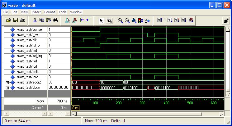
30 ModelSim Simulation
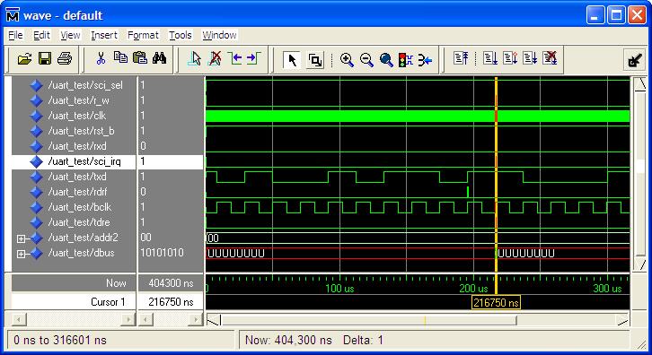
31 ModelSim Simulation
32 Loop-Back Test RxD <= TxD; process begin wait for 120 ns; report "Begin Testing"; rst_b <= '1'; SCI_sel <= '1'; -- Set SCCR DBUS <= " "; ADDR2 <= "10"; R_W <= '1'; wait for 100 ns; -- Load TDR DBUS <= " "; ADDR2 <= "00"; wait for 100 ns; DBUS <= "ZZZZZZZZ"; R_W <= '0'; wait until RDRF = '1'; assert DBUS = " " report "Test Failed"; report "Testing Complete"; wait;

33 Loop-Back Test
34 Summary Universal Asynchronous Receiver Transmitter Transmitter Receiver Baud Rate Generator VHDL Models ModelSim Simulation
SERIAL COMMUNICATION BY USING UART
 SERIAL COMMUNICATION BY USING UART A THESIS SUBMITTED IN PARTIAL FULFILLMENT OF THE REQUIREMENTS FOR THE DEGREE OF BACHELOR OF TECHNOLOGY IN ELECTRONICS AND INSTRUMENTATION ENGINEERING BY Pradosh Priyadarshan
Sequential Logic - Module 5
 Sequential Logic Module 5 Jim Duckworth, WPI 1 Latches and Flip-Flops Implemented by using signals in IF statements that are not completely specified Necessary latches or registers are inferred by the
SCI Serial Communication Interface
 SCI Serial Communication Interface Gerrit Becker James McClearen Charlie Hagadorn October 21, 2004 1 Learning Objectives of the Overview Knowledge of the general differences between serial and parallel
The University of Alabama in Huntsville ECE Department CPE Midterm Exam Solution Spring 2016
 The University of Alabama in Huntsville ECE Department CPE 526 01 Midterm Exam Solution Spring 2016 1. (15 points) Write a VHDL function that accepts a std_logic_vector of arbitrary length and an integer
VHDL in 1h. Martin Schöberl
 VHDL in 1h Martin Schöberl VHDL /= C, Java, Think in hardware All constructs run concurrent Different from software programming Forget the simulation explanation VHDL is complex We use only a small subset
The University of Alabama in Huntsville Electrical and Computer Engineering CPE/EE 422/522 Spring 2005 Homework #6 Solution
 5.3(a)(2), 5.6(c)(2), 5.2(2), 8.2(2), 8.8(2) The University of Alabama in Huntsville Electrical and Computer Engineering CPE/EE 422/522 Spring 25 Homework #6 Solution 5.3 (a) For the following SM chart:
 X:\PDP-8\iob\FPGA\iob1\iob_cfg.vhd library IEEE; use IEEE.STD_LOGIC_1164.ALL; use IEEE.numeric_std.ALL; package IOB_Config is constant OSCFREQ: integer := 50000000; constant NUMUARTS: integer := 3; subtype
Summary of FPGA & VHDL
 FYS4220/9220 Summary of FPGA & VHDL Lecture #6 Jan Kenneth Bekkeng, University of Oslo - Department of Physics 16.11.2011 Curriculum (VHDL & FPGA part) Curriculum (Syllabus) defined by: Lectures Lecture6:
Design Examples. ELEC 418 Advanced Digital Systems Dr. Ron Hayne. Images Courtesy of Cengage Learning
 Design Examples ELEC 418 Advanced Digital Systems Dr. Ron Hayne Images Courtesy of Cengage Learning BCD to 7-Segment Display 418_04 2 BCD to 7-Segment Display entity BCD_Seven is port(bcd: in std_logic_vector(3
Control Unit: Binary Multiplier. Arturo Díaz-Pérez Departamento de Computación Laboratorio de Tecnologías de Información CINVESTAV-IPN
 Control Unit: Binary Multiplier Arturo Díaz-Pérez Departamento de Computación Laboratorio de Tecnologías de Información CINVESTAV-IPN Example: Binary Multiplier Two versions Hardwired control Microprogrammed
Corrections for Digital Systems Design Using VHDL, 3rd printing
 Corrections for Digital Systems Design Using VHDL, 3rd printing Corrected VHDL code can be found on the web page: http://www.brookscole.com/engineering/ee/roth.html line 7 means 7th line from bottom, etc.
VHDL Testbench. Test Bench Syntax. VHDL Testbench Tutorial 1. Contents
 VHDL Testbench Tutorial 1 Contents 1 VHDL Testbench 2 Test Bench Syntax 3 Testbench Example: VHDL Code for Up Down Binary Counter 4 VHDL Testbench code for up down binary counter 5 Testbench Waveform for
Codec. WM8731 Audio Codec
 Codec WM8731 Audio Codec Codec Coder / Decoder Audio, Video Compression/decompression signal coding 2 tj WM8731 3 tj WM8731 Data Path Basic Connection 4 tj WM8731 Data Path Basic Timing 5 tj WM8731 Data
A B C D E F 0480 FE B F5 3B FC F3 E 1A 1D 2A 2D 3A 3D 4A 4D 5A 5D 6A 6D 7A 7D
 What's on the 9S12 bus as it executes a program The 9S12 Serial Communications Interface 9S12 Serial Communications Interface (SCI) Block Guide V02.05 Huang, Sections 9.2-9.6 Consider a 9S12 executing
VHDL. ELEC 418 Advanced Digital Systems Dr. Ron Hayne. Images Courtesy of Cengage Learning
 VHDL ELEC 418 Advanced Digital Systems Dr. Ron Hayne Images Courtesy of Cengage Learning Design Flow 418_02 2 VHDL Modules 418_02 3 VHDL Libraries library IEEE; use IEEE.std_logic_1164.all; std_logic Single-bit
Test Benches - Module 8
 Test Benches Module 8 Jim Duckworth, WPI 1 Overview We have concentrated on VHDL for synthesis Can also use VHDL as a test language Very important to conduct comprehensive verification on your design To
MAX 10. Memory Modules
 MAX 10 Memory Modules Three types of on-chip memory FF based memory embedded in the LEs Most efficient for very small memories Compiler driven Embedded SRAM block 8K bits + 1024 parity bits (9216b) MAX
1. Specifications Functions Used Operation Software Flowcharts Program Listing... 13
 APPLICATION NOTE SH7145F Summary The SH7144 series is a single-chip microprocessor based on the SH-2 RISC (Reduced Instruction Set Computer) CPU core and integrating a number of peripheral functions. This
VHDL And Synthesis Review
 VHDL And Synthesis Review VHDL In Detail Things that we will look at: Port and Types Arithmetic Operators Design styles for Synthesis VHDL Ports Four Different Types of Ports in: signal values are read-only
8-1. Fig. 8-1 ASM Chart Elements 2001 Prentice Hall, Inc. M. Morris Mano & Charles R. Kime LOGIC AND COMPUTER DESIGN FUNDAMENTALS, 2e, Updated.
 8-1 Name Binary code IDLE 000 Register operation or output R 0 RUN 0 1 Condition (a) State box (b) Example of state box (c) Decision box IDLE R 0 From decision box 0 1 START Register operation or output
Quartus Counter Example. Last updated 9/6/18
 Quartus Counter Example Last updated 9/6/18 Create a logic design from start to a DE10 implementation This example uses best design practices This example is not about creating HDL The HDL code will be
Counters. Counter Types. Variations. Modulo Gray Code BCD (Decimal) Decade Ring Johnson (twisted ring) LFSR
 Decade Ring Johnson (twisted ring) LFSR") CE 1911 Counters Counter Types Modulo Gray Code BC (ecimal) ecade Ring Johnson (twisted ring) LFSR Variations Asynchronous / Synchronous Up/own Loadable 2 tj Modulo-n (n = a power of 2) Asynchronous Count
CE 1911 Counters Counter Types Modulo Gray Code BC (ecimal) ecade Ring Johnson (twisted ring) LFSR Variations Asynchronous / Synchronous Up/own Loadable 2 tj Modulo-n (n = a power of 2) Asynchronous Count
VHDL for Modeling - Module 10
 VHDL for Modeling Module 10 Jim Duckworth, WPI 1 Overview General examples AND model Flip-flop model SRAM Model Generics DDR SDRAM Model Constraints Metastability Block Statements Just for reference Jim
Problem Set 10 Solutions
 CSE 260 Digital Computers: Organization and Logical Design Problem Set 10 Solutions Jon Turner thru 6.20 1. The diagram below shows a memory array containing 32 words of 2 bits each. Label each memory
DIGITAL LOGIC DESIGN VHDL Coding for FPGAs Unit 6
 DIGITAL LOGIC DESIGN VHDL Coding for FPGAs Unit 6 FINITE STATE MACHINES (FSMs) Moore Machines Mealy Machines Algorithmic State Machine (ASM) charts FINITE STATE MACHINES (FSMs) Classification: Moore Machine:
Example 58: Traffic Lights
 208 Chapter 8 Listing 8.7(cont.) doorlock2_top.vhd btn012
In our case Dr. Johnson is setting the best practices
 VHDL Best Practices Best Practices??? Best practices are often defined by company, toolset or device In our case Dr. Johnson is setting the best practices These rules are for Class/Lab purposes. Industry
EL 310 Hardware Description Languages Midterm
 EL 3 Hardware Description Languages Midterm 2 3 4 5 Total Name: ID : Notes: ) Please answer the questions in the provided space after each question. 2) Duration is minutes 3) Closed books and closed notes.
[VARIABLE declaration] BEGIN. sequential statements
![[VARIABLE declaration] BEGIN. sequential statements](/thumbs/89/98890993.jpg "[VARIABLE declaration] BEGIN. sequential statements") PROCESS statement (contains sequential statements) Simple signal assignment statement
PROCESS statement (contains sequential statements) Simple signal assignment statement
Timing in synchronous systems
 BO 1 esign of sequential logic Outline Timing in synchronous networks Synchronous processes in VHL VHL-code that introduces latches andf flip-flops Initialization of registers Mealy- and Moore machines
Review for Exam 3. Write 0x05 to ATD0CTL4 to set at fastest conversion speed and 10-bit conversions
 Review for Exam 3 A/D Converter Power-up A/D converter (ATD0CTL2) Write 0x05 to ATD0CTL4 to set at fastest conversion speed and 10-bit conversions Write 0x85 to ATD0CTL4 to set at fastest conversion speed
Dallas Semiconductor DS1307 Real Time Clock. The DS 1307 is a real-time clock with 56 bytes of NV (nonvolatile)
") Using the MC9S12 IIC Bus with DS 1307 Real Time Clock DS1307 Data Sheet Asynchronous Serial Communications The MC9S12 Serial Communications Interface (SCI) Dallas Semiconductor DS1307 Real Time Clock The
Using the MC9S12 IIC Bus with DS 1307 Real Time Clock DS1307 Data Sheet Asynchronous Serial Communications The MC9S12 Serial Communications Interface (SCI) Dallas Semiconductor DS1307 Real Time Clock The
8-1. Fig. 8-1 ASM Chart Elements 2001 Prentice Hall, Inc. M. Morris Mano & Charles R. Kime LOGIC AND COMPUTER DESIGN FUNDAMENTALS, 2e, Updated.
 8-1 Name Binary code IDLE 000 Register operation or output R 0 RUN Condition (a) State box (b) Example of state box (c) Decision box IDLE R 0 From decision box START Register operation or output PC 0 (d)
The block diagram representation is given below: The output equation of a 2x1 multiplexer is given below:
 Experiment-3: Write VHDL programs for the following circuits, check the wave forms and the hardware generated a. multiplexer b. De-Multiplexer Objective: i. To learn the VHDL coding for Multiplexer and
Multiplication Simple Gradeschool Algorithm for 16 Bits (32 Bit Result)
") Multiplication Simple Gradeschool Algorithm for 16 Bits (32 Bit Result) Input Input Multiplier Multiplicand AND gates 16 Bit Adder 32 Bit Product Register Multiplication Simple Gradeschool Algorithm for
Multiplication Simple Gradeschool Algorithm for 16 Bits (32 Bit Result) Input Input Multiplier Multiplicand AND gates 16 Bit Adder 32 Bit Product Register Multiplication Simple Gradeschool Algorithm for
MCPU - A Minimal 8Bit CPU in a 32 Macrocell CPLD.
 MCPU - A Minimal 8Bit CPU in a 32 Macrocell CPLD. Tim Böscke, cpldcpu@opencores.org 02/2001 - Revised 10/2004 This documents describes a successful attempt to fit a simple VHDL - CPU into a 32 macrocell
Asynchronous Data Transfer
 Asynchronous Data Transfer In asynchronous data transfer, there is no clock line between the two devices Both devices use internal clocks with the same frequency Both devices agree on how many data bits
COVER SHEET: Total: Regrade Info: 5 (14 points) 7 (15 points) Midterm 1 Spring 2012 VERSION 1 UFID:
 7 (15 points) Midterm 1 Spring 2012 VERSION 1 UFID:") EEL 4712 Midterm 1 Spring 2012 VERSION 1 Name: UFID: IMPORTANT: Please be neat and write (or draw) carefully. If we cannot read it with a reasonable effort, it is assumed wrong. As always, the best answer
EEL 4712 Midterm 1 Spring 2012 VERSION 1 Name: UFID: IMPORTANT: Please be neat and write (or draw) carefully. If we cannot read it with a reasonable effort, it is assumed wrong. As always, the best answer
DIGITAL LOGIC WITH VHDL (Fall 2013) Unit 6
 Unit 6") DIGITAL LOGIC WITH VHDL (Fall 2013) Unit 6 FINITE STATE MACHINES (FSMs) Moore Machines Mealy Machines FINITE STATE MACHINES (FSMs) Classification: Moore Machine: Outputs depend only on the current state
DIGITAL LOGIC WITH VHDL (Fall 2013) Unit 6 FINITE STATE MACHINES (FSMs) Moore Machines Mealy Machines FINITE STATE MACHINES (FSMs) Classification: Moore Machine: Outputs depend only on the current state
The University of Alabama in Huntsville ECE Department CPE Midterm Exam Solution March 2, 2006
 The University of Alabama in Huntsville ECE Department CPE 526 01 Midterm Exam Solution March 2, 2006 1. (15 points) A barrel shifter is a shift register in which the data can be shifted either by one
CS/ECE 5780/6780: Embedded System Design
 CS/ECE 5780/6780: Embedded System Design John Regehr Lecture 16: SCI Register Configuration and Ritual SCI Register Information & Terminology The information in this lecture is found: Textbook pages 346-9.
EENG 2910 Project III: Digital System Design. Due: 04/30/2014. Team Members: University of North Texas Department of Electrical Engineering
 EENG 2910 Project III: Digital System Design Due: 04/30/2014 Team Members: University of North Texas Department of Electrical Engineering Table of Content i Contents Abstract...3 Introduction...3 Report...4
Very High Speed Integrated Circuit Har dware Description Language
 Very High Speed Integrated Circuit Har dware Description Language Industry standard language to describe hardware Originated from work in 70 s & 80 s by the U.S. Departm ent of Defence Root : ADA Language
APPLICATION NOTE CPLDs
 APPLICATION NOTE Implementing a UART in Philips Programmable Logic Software 1997 May 06 Implementing a UART in Philips INTRODUCTION The Universal Asynchronous Receiver Transmitter (UART) has been the most
Example 15: Moving Sprites with Flash Background
 Displaying an Image Read from Flash Memory 95 Listing 2.5 (cont.) vga_flash_n2_top.vhd clr
Lecture 4: Modeling in VHDL (Continued ) EE 3610 Digital Systems
 EE 3610 Digital Systems") EE 3610: Digital Systems 1 Lecture 4: Modeling in VHDL (Continued ) Sequential Statements Use Process process (sensitivity list) variable/constant declarations Sequential Statements end process; 2 Sequential
EE 3610: Digital Systems 1 Lecture 4: Modeling in VHDL (Continued ) Sequential Statements Use Process process (sensitivity list) variable/constant declarations Sequential Statements end process; 2 Sequential
3 Designing Digital Systems with Algorithmic State Machine Charts
 3 Designing with Algorithmic State Machine Charts An ASM chart is a method of describing the sequential operations of a digital system which has to implement an algorithm. An algorithm is a well defined
constant reg_init: std_logic_vector(11 downto 0):=" ";
:= ;") -- UART Package Declaration -- -- by Weijun Zhang, 05/2001 library ieee; use ieee.std_logic_1164.all; package my_package is FUNCTION parity(inputs: std_logic_vector(7 downto 0)) RETURN std_logic; end my_package;
-- UART Package Declaration -- -- by Weijun Zhang, 05/2001 library ieee; use ieee.std_logic_1164.all; package my_package is FUNCTION parity(inputs: std_logic_vector(7 downto 0)) RETURN std_logic; end my_package;
Experiment 0 OR3 Gate ECE 332 Section 000 Dr. Ron Hayne June 8, 2003
 Experiment 0 OR3 Gate ECE 332 Section 000 Dr. Ron Hayne June 8, 2003 On my honor I have neither received nor given aid on this report. Signed: Ronald J. Hayne Part I Description of the Experiment Experiment
ECE/CS 5780/6780: Embedded System Design
 ECE/CS 5780/6780: Embedded System Design Scott R. Little Lecture 16: SCI Register Configuration and Ritual Scott R. Little (Lecture 16: SCI Config) ECE/CS 5780/6780 1 / 19 Administrivia Schedule This is
Synthesis from VHDL. Krzysztof Kuchcinski Department of Computer Science Lund Institute of Technology Sweden
 Synthesis from VHDL Krzysztof Kuchcinski Krzysztof.Kuchcinski@cs.lth.se Department of Computer Science Lund Institute of Technology Sweden March 23, 2006 Kris Kuchcinski (LTH) Synthesis from VHDL March
Design Problem 5 Solutions
 CS/EE 260 Digital Computers: Organization and Logical Design Design Problem 5 Solutions Jon Turner Due 5/4/04 1. (100 points) In this problem, you will implement a simple shared memory multiprocessor system
EEL 4712 Digital Design Test 1 Spring Semester 2007
 IMPORTANT: Please be neat and write (or draw) carefully. If we cannot read it with a reasonable effort, it is assumed wrong. COVER SHEET: Problem: Points: 1 (15 pts) 2 (20 pts) Total 3 (15 pts) 4 (18 pts)
EE 3170 Microcontroller Applications
 Block Diagram of 68HC11A8 EE 3170 Microcontroller Applications Lecture 14: Advanced 68HC11 Hardware- Part II: Serial Communications Interfacing - Miller 7.10 Interrupt control Clock Mode control A/D ref.
ECE 545 Lecture 8. Data Flow Description of Combinational-Circuit Building Blocks. George Mason University
 ECE 545 Lecture 8 Data Flow Description of Combinational-Circuit Building Blocks George Mason University Required reading P. Chu, RTL Hardware Design using VHDL Chapter 7, Combinational Circuit Design:
The University of Alabama in Huntsville ECE Department CPE Final Exam Solution Spring 2004
 The University of Alabama in Huntsville ECE Department CPE 526 01 Final Exam Solution Spring 2004 1. (15 points) An old Thunderbird car has three left and three right tail lights, which flash in unique
Symbolically the RS-Latch that is being simulated is the one shown below, it s truth table is also given:
 Symbolically the RS-Latch that is being simulated is the one shown below, it s truth table is also given: For this example you will need to create two VHDL (.vhd) files one represents the rslatch itself,
Design Problem 4 Solutions
 CSE 260 Digital Computers: Organization and Logical Design Design Problem 4 Solutions Jon Turner The block diagram appears below. The controller includes a state machine with three states (normal, movecursor,
FSM Components. FSM Description. HDL Coding Methods. Chapter 7: HDL Coding Techniques
 FSM Components XST features: Specific inference capabilities for synchronous Finite State Machine (FSM) components. Built-in FSM encoding strategies to accommodate your optimization goals. You may also
Lecture 12 VHDL Synthesis
 CPE 487: Digital System Design Spring 2018 Lecture 12 VHDL Synthesis Bryan Ackland Department of Electrical and Computer Engineering Stevens Institute of Technology Hoboken, NJ 07030 1 What is Synthesis?
6.111 Lecture # 8. Topics for Today: (as time permits)
") 6.111 Lecture # 8 Topics for Today: (as time permits) 1. Memories 2. Assembling 'packages' for designs 3. Discussion of design procedure 4. Development of a design example using a finite state machine
6.111 Lecture # 8 Topics for Today: (as time permits) 1. Memories 2. Assembling 'packages' for designs 3. Discussion of design procedure 4. Development of a design example using a finite state machine
 Esempio FSM Description : library IEEE; use IEEE.std_logic_1164.all; use IEEE.std_logic_arith.all; use IEEE.std_logic_unsigned.all; entity esempiofsm is port ( clk: in STD_LOGIC; p: in STD_LOGIC; reset:
VHDL Modeling Behavior from Synthesis Perspective -Part B - EL 310 Erkay Savaş Sabancı University
 VHDL Modeling Behavior from Synthesis Perspective -Part B - EL 310 Erkay Savaş Sabancı University 1 The Wait Statement Syntax wait until condition; Different forms wait until(clk event and clk = 1 ); wait
Exercise: how can we do?
 : how can we do? Create special inter-process communication channels: the signals Interleave execution phases and signal update phase Signal assignments during execution phase are recorded and delayed;
Understand the design and operation of the SCI and the I 2 C, IrDA and Smart Card interfaces
 Module Introduction Purpose This training module provides an overview of the serial communication interface (SCI), I 2 C interface, IrDA interface and Smart Card interface built into H8S series MCUs. Objective
COE 405, Term 062. Design & Modeling of Digital Systems. HW# 1 Solution. Due date: Wednesday, March. 14
 COE 405, Term 062 Design & Modeling of Digital Systems HW# 1 Solution Due date: Wednesday, March. 14 Q.1. Consider the 4-bit carry-look-ahead adder (CLA) block shown below: A 3 -A 0 B 3 -B 0 C 3 4-bit
Lattice VHDL Training
 Lattice Part I February 2000 1 VHDL Basic Modeling Structure February 2000 2 VHDL Design Description VHDL language describes a digital system as a set of modular blocks. Each modular block is described
Test Bench. Top Level Model Test Bench MUT
 A test bench is usually a simulation-only model used for design verification of some other model(s) to be synthesized. A test bench is usually easier to develop than a force file when verifying the proper
Constructing VHDL Models with CSA
 Constructing VHDL Models with CSA List all components (e.g., gate) inclusive propagation delays. Identify input/output signals as input/output ports. All remaining signals are internal signals. Identify
RTL Design. Gate-level design is now rare! RTL = Register Transfer Level
 RTL Design Gate-level design is now rare! design automation is necessary to manage the complexity of modern circuits only library designers use gates automated RTL synthesis is now almost universal RTL
DESCRIPTION OF DIGITAL CIRCUITS USING VHDL
 DESCRIPTION OF DIGITAL CIRCUITS USING VHDL Combinatinal circuits Sequential circuits Design organization. Generic design Iterative operations Authors: Luis Entrena Arrontes, Celia López, Mario García,
Luleå University of Technology Kurskod SMD152 Datum Skrivtid
 Luleå University of Technology Kurskod SMD152 Datum 2003-10-24 Skrivtid 9.00 13.00 1 Manual synthesis (10 p, 2 p each) Here you are given five different VHDL models. Your task is to draw the schematics
EEL 4712 Digital Design Test 1 Spring Semester 2008
 IMPORTANT: Please be neat and write (or draw) carefully. If we cannot read it with a reasonable effort, it is assumed wrong. Also, as always, the best answer gets the most points. COVER SHEET: Problem:
CSE 260 Introduction to Digital Logic and Computer Design. Exam 1. Your name 2/13/2014
 CSE 260 Introduction to Digital Logic and Computer Design Jonathan Turner Exam 1 Your name 2/13/2014 1. (10 points) Draw a logic diagram that implements the expression A(B+C)(C +D)(B+D ) directly (do not
Problem Set 5 Solutions
 Problem Set 5 Solutions library ieee; use ieee.std_logic_1164.all; use work.std_arith.all; -- here is the declaration of entity entity la_rewarder is port (clk, go, SRAM_busy, SRAM_rdy: in std_logic; min:
Schedule. ECE U530 Digital Hardware Synthesis. Rest of Semester. Midterm Question 1a
 ECE U530 Digital Hardware Synthesis Prof. Miriam Leeser mel@coe.neu.edu November 8, 2006 Midterm Average: 70 Lecture 16: Midterm Solutions Homework 6: Calculator Handshaking HW 6: Due Wednesday, November
VHDL. Chapter 7. Behavioral Modeling. Outline. Behavioral Modeling. Process Statement
 Chapter 7 VHDL VHDL - Flaxer Eli Ch 7-1 Process Statement Outline Signal Assignment Statement Variable Assignment Statement Wait Statement If-Then-Else Statement Case Statement Null Statement Loop Statement
COVER SHEET: Total: Regrade Info: 1 (8 points) 2 ( 8 points) 3 (16 points) 4 (16 points) 5 (16 points) 6 (16 points) 7 (16 points) 8 (8 points)
 2 ( 8 points) 3 (16 points) 4 (16 points) 5 (16 points) 6 (16 points) 7 (16 points) 8 (8 points)") EEL 4712 Midterm 1 Spring 2010 VERSION 1 Name: UFID: IMPORTANT: Please be neat and write (or draw) carefully. If we cannot read it with a reasonable effort, it is assumed wrong. As always, the best answer
EEL 4712 Midterm 1 Spring 2010 VERSION 1 Name: UFID: IMPORTANT: Please be neat and write (or draw) carefully. If we cannot read it with a reasonable effort, it is assumed wrong. As always, the best answer
VHDL. Official Definition: VHSIC Hardware Description Language VHISC Very High Speed Integrated Circuit
 VHDL VHDL Official Definition: VHSIC Hardware Description Language VHISC Very High Speed Integrated Circuit VHDL Alternative (Student Generated) Definition Very Hard Digital Logic language VHDL Design
HCS12 Serial Communications Interface (SCI) Block Guide V02.06
 Block Guide V02.06") DOCUMENT NUMBER S12SCIV2/D HCS12 Serial Communications Interface (SCI) Block Guide V02.06 Original Release Date: June 4, 1999 Revised: Oct 10, 2001 Motorola, Inc. Motorola reserves the right to make changes
DOCUMENT NUMBER S12SCIV2/D HCS12 Serial Communications Interface (SCI) Block Guide V02.06 Original Release Date: June 4, 1999 Revised: Oct 10, 2001 Motorola, Inc. Motorola reserves the right to make changes
Lecture 5: State Machines, Arrays, Loops. EE 3610 Digital Systems
 EE 3610: Digital Systems 1 Lecture 5: State Machines, Arrays, Loops BCD to Excess-3 (XS 3 ) Code Converter Example: Fig. 2-53 2 Easier to use one type of code (e.g. XS 3 ) over the other type (e.g. BCD)
Sequential Statement
 Sequential Statement Sequential Logic Output depends not only on current input values but also on previous input values. Are building blocks of; Counters Shift registers Memories Flip flops are basic sequential
IT T35 Digital system desigm y - ii /s - iii
 UNIT - V Introduction to Verilog Hardware Description Language Introduction HDL for combinational circuits Sequential circuits Registers and counters HDL description for binary multiplier. 5.1 INTRODUCTION
AN Multifunction Serial Interface of FM MCU. Contents. 1 Introduction
 AN99218 Author: Edison Zhang Associated Part Family: FM0+, FM3, FM4 Associated Code Examples: None Related Application Notes: None AN99218 explains the various modes of the multifunction serial (MFS) interface.
ENGR 5865 DIGITAL SYSTEMS
 ENGR 5865 DIGITAL SYSTEMS ModelSim Tutorial Manual January 22, 2007 Introduction ModelSim is a CAD tool widely used in the industry for hardware design. This document describes how to edit/add, compile
CSE 260 Digital Computers: Organization and Logical Design. Exam 2. Jon Turner 3/28/2012
 CSE 260 Digital Computers: Organization and Logical Design Exam 2 Jon Turner 3/28/2012 1. (15 points). Draw a diagram for a circuit that implements the VHDL module shown below. Your diagram may include
VHDL Simulation. Testbench Design
 VHDL Simulation Testbench Design The Test Bench Concept Elements of a VHDL/Verilog testbench Unit Under Test (UUT) or Device Under Test (DUT) instantiate one or more UUT s Stimulus of UUT inputs algorithmic
Concurrent & Sequential Stmts. (Review)
") VHDL Introduction, Part II Figures in this lecture are from: Rapid Prototyping of Digital Systems, Second Edition James O. Hamblen & Michael D. Furman, Kluwer Academic Publishers, 2001, ISBN 0-7923-7439-
VHDL Introduction, Part II Figures in this lecture are from: Rapid Prototyping of Digital Systems, Second Edition James O. Hamblen & Michael D. Furman, Kluwer Academic Publishers, 2001, ISBN 0-7923-7439-
CMPT 250: Computer Architecture. Using LogicWorks 5. Tutorial Part 1. Somsubhra Sharangi
 CMPT 250: Computer Architecture Using LogicWorks 5 Tutorial Part 1 Somsubhra Sharangi What is VHDL? A high level language to describe digital circuit Different that a programming language ( such as Java)
Sign here to give permission for your test to be returned in class, where others might see your score:
 EEL 4712 Midterm 2 Spring 216 VERSION 1 Name: UFID: Sign here to give permission for your test to be returned in class, where others might see your score: IMPORTANT: Please be neat and write (or draw)
The CPU Bus : Structure 0
 The CPU Bus : Structure 0 The following can be applied to both the internal CPU buses and the external system buses. This distinction becomes blurred when we discuss Systems on a single Chip (SoC). The
Modeling Complex Behavior
 Modeling Complex Behavior Sudhakar Yalamanchili, Georgia Institute of Technology, 2006 (1) Outline Abstraction and the Process Statement Concurrent processes and CSAs Process event behavior and signals
Universal Asynchronous Receiver Transmitter (UART ) CSCE 612 Project #2 Specification
 CSCE 612 Project #2 Specification") Universal Asynchronous Receiver Transmitter (UART - 8251) CSCE 612 Project #2 Specification VLSI Design Lab Department of Computer Science and Engineering University of South Carolina Dr. James P. Davis
Universal Asynchronous Receiver Transmitter (UART - 8251) CSCE 612 Project #2 Specification VLSI Design Lab Department of Computer Science and Engineering University of South Carolina Dr. James P. Davis
Lecture 27. Structural Description of a 3-Bit Synchronous Decade Counter. FIGURE 4.31 A State diagram of a decade counter.
 Lecture 27 Structural Description of a 3-Bit Synchronous Decade Counter FIGURE 4.31 A State diagram of a decade counter. FIGURE 4.31B K - maps for a decade counter. FIGURE 4.32 Logic diagram of a decade
Introduction to Computer Design
 Introduction to Computer Design Memory (W 800-840) Basic processor operation Processor organization Executing instructions Processor implementation using VHDL 1 Random Access Memory data_in address read/write
ECEU530. Schedule. ECE U530 Digital Hardware Synthesis. Datapath for the Calculator (HW 5) HW 5 Datapath Entity
 HW 5 Datapath Entity") ECE U530 Digital Hardware Synthesis Prof. Miriam Leeser mel@coe.neu.edu November 6, 2006 Classes November 6 and 8 are in 429 Dana! Lecture 15: Homework 5: Datapath How to write a testbench for synchronous
ECE U530 Digital Hardware Synthesis Prof. Miriam Leeser mel@coe.neu.edu November 6, 2006 Classes November 6 and 8 are in 429 Dana! Lecture 15: Homework 5: Datapath How to write a testbench for synchronous
Hierarchy of I/O Control Devices
 Hierarchy of I/O Control Devices 8155 I/O + Timer 2 Port (A,B), No Bidirectional HS mode (C) 4 mode timer 8253/54 Timer 6 mode timer 8255 I/O 2 Port (A,B) A is Bidirectional HS mode (C) Extra controls
Symbolically a D-Latch can be represented as so, it s truth table is also given:
 Symbolically a D-Latch can be represented as so, it s truth table is also given: For this example you will need to create two VHDL (.vhd) files one represents the dlatch itself, while the other will test
VHDL Testbench Design. Textbook chapters 2.19, , 9.5
 VHDL Testbench Design Textbook chapters 2.19, 4.10-4.12, 9.5 The Test Bench Concept Elements of a VHDL/Verilog testbench Unit Under Test (UUT) or Device Under Test (DUT) instantiate one or more UUT s Stimulus
13/06/56 8 ก ก. 08-Case Study
 8 ก ก ก 1 ก 2 1 3 VHDL DIVIDER200Hz use IEEE.std_logic_1164.all; entity DIVIDER200Hz is generic (fin: integer :=25000000; --Input frequency fout: integer :=200); --Output frequency end DIVIDER200Hz; architecture