Chapter 2: Combinational Systems
|
|
|
- Bonnie Hardy
- 6 years ago
- Views:
Transcription
1 Uchechukwu Ofoegbu Chapter 2: Combinational Systems Temple University Adapted from Alan Marcovitz s Introduction to Logic and Computer Design
2 Riddle Four switches can be turned on or off. One is the switch for the incandescent overhead light in the next room, which is initially off, but you don't know which. The other three switches do nothing. From the room with the switches in it, you can't see whether the light in the next room is turned on or off. You may flip the switches as often and as many times as you like, but once you enter the next room to check on the light, you must be able to say which switch controls the light without flipping the switches any further. (And you can't open the door without entering, either!) How can you determine which switch controls the light?
3 Design Process for Combinational Systems Begins with a verbal description of the intended system, known as the PROBLEM STATEMENT A block diagram of the system should be developed The desired objectives and constraints
4 Illustrations 1. A system with four inputs, A, B, C, and D, and one output, Z, such that Z = 1 iff three of the inputs are A single light (that can be on or off) that can be controlled by any one of three switches. One switch is the master on/off switch. If it is off, the lights are off. When the master switch is on, a change in the position of one of the other switches (from up to down or from down to up) will cause the light to change state. 3. A system to do 1 bit of binary addition. It has three inputs (the 2 bits to be added plus the carry from the next lower order bit) and produces two outputs, a sum bit and a carry to the next higher order position.
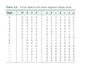
5 Illustrations 4. A system that has as its input the code for a decimal digit, and produces as its output the signals to drive a sevensegment display, such as those on most digital watches and numeric displays. 5. A system with nine inputs, representing two 4-bit binary numbers and a carry input, and one 5-bit output, representing the sum. (Each input number can range from 0 to 15; the output can range from 0 to 31.)

6 Design Steps 1. Represent each of the inputs and output in binary. This is sometimes taken care of in the problem statement (ex 1, 3, 5) 2. Formalize the design specification either in the form of a truth table or of an algebraic expression. There are 2 n input combinations for n inputs in a truth table. Truth tables are written in binary order to avoid omissions. If necessary, break the problem into smaller subproblems before or after creating the truth tables.
7 Design Steps 3. Simplify the description. Most times expressions have to be converted to algebraic forms Several techniques exist for reducing complexity of algebraic forms 4. Implement the system with the available components, subject to the design objectives and constraints. Gates are the most common components A gate is a network with one output The less number of gates required, the more desirable the system is, since each signal passing through a gate introduces a delay in the system. More complex systems can be used in addition to gates (ex. Adders, decoders, e.t.c.).
8 Don t t Care Conditions Don t cares occur when The output is not specified for all input combinations, so for the remaining input combinations, it doesn t matter There are input combinations that don t occur in the system Flip-flops one systems drives another When we just don t care Don t cares are represented by X in a truth table. The output of the combination could either be a 1 or a 0.
9 Developing Truth Tables 1. A system with four inputs, A, B, C, and D, and one output, Z, such that Z = 1 iff three of the inputs are 1.

10 2. A single light (that can be on or off) that can be controlled by any one of three switches. One switch is the master on/off switch. If it is off, the lights are off. When the master switch is on, a change in the position of one of the other switches (from up to down or from down to up) will cause the light to change state.
11 4. A system that has as its input the code for a decimal digit, and produces as its output the signals to drive a seven-segment display
12
13 Switching Algebra 3. Simplify the description. Most times expressions have to be converted to algebraic forms Several techniques exist for reducing complexity of algebraic forms 4. Implement the system with the available components, subject to the design objectives and constraints. Gates are the most common components A gate is a network with one output The less number of gates required, the more desirable the system is, since each signal passing through a gate introduces a delay in the system. More complex systems can be used in addition to gates (ex. Adders, decoders, e.t.c.).
14 Switching Algebra Basic Digital logic is based on 3 primary functions (the basic gates): AND OR NOT
15 The AND function: The AND function If all the inputs are high is the output is high If any input is low, the output is low If this input AND this input are high, the output is high
16 AND Logic Symbol Inputs Output If both inputs are 1, the output is 1 If any input is 0, the output is 0
17 AND Logic Symbol Inputs Output Determine the output
18 AND Logic Symbol Inputs Output Determine the output
19 AND Logic Symbol Inputs Output Determine the output
20 AND Truth Table To help understand the function of a digital device, a Truth Table is used: Every possible input combination Input Output AND Function
21 AND Gates It is possible to have AND gates with more than 2 inputs. The same logic rules apply if any input
22 The OR function: The OR function if any input is high, the output is high if all inputs are low, the output is low If this input OR this input is high, the output is high
23 OR Logic Symbol Inputs Output If any input is 1, the output is 1 If all inputs are 0, the output is 0
24 OR Logic Symbol Inputs Output Determine the output
25 OR Logic Symbol Inputs 0 1 Output 1 Determine the output
26 OR Logic Symbol Inputs 1 1 Output 1 Determine the output
27 Truth Table Input Output OR Truth Table OR Function
28 The NOT function: The NOT function If any input is high, the output is low If any input is low, the output is high The output is the opposite state of the input The NOT function is often called INVERTER
29 NOT Logic Symbol Input Output If the input is 1, the output is 0 If the input is 0, the output is 1
30 NOT Logic Symbol Input 0 1 Output Determine the output
31 NOT Logic Symbol Input 1 0 Output Determine the output
32 Summary OR (written as +)1 a + b (read a OR b) is 1 if and only if a = 1 or b = 1 or both AND (written as or simply two variables catenated) a b = ab (read a AND b) is 1 if and only if a = 1 and b = 1. NOT (written ) a (read NOT a) is 1 if and only if a = 0
33
34 Literal: The appearance of a variable or its complement. Product Term: one or more literals connected by AND operators. Definitions Standard product term: Also called minterm product term that includes each variable of the problem, either uncomplemented or complemented. Sum of products expression (often abbreviated SOP) one or more product terms connected by OR operators. A canonical sum or sum of standard product terms: a sum of products expression where all of the terms are standard product terms.
35 A Minimum Sum of Products expression: one of those SOP expressions for a function that has the fewest number of product terms. If there is more than one expression with the fewest number of terms, then minimum is defined as one or more of those expressions with the fewest number of literals. (1) x yz + x yz + xy z + xy z + xyz 5 terms, 15 literals (2) x y + xy + xyz 3 terms, 7 literals (3) x y + xy + xz 3 terms, 6 literals (4) x y + xy + yz 3 terms, 6 literals Definitions
36 Simplification x yz + x yz + xy z + xy z + xyz 5 terms, 15 literals = (x yz +x yz)+(xy z + xy z) + xyz associative = x y(z+z ) + xy (z+z ) + xyz distributive = x y.1 +xy.1 +xyz = x y + xy + xyz adjacency complement = x y + xy + xz identity Down to three terms and seven literals
37 x yz + x yz + xy z + xy z + xyz + xy z 5 terms, 15 literals = (x yz +x yz)+(xy z + xy z) + (xyz + xy z) associative = x y + xy + xz adjacency Simplification Reduce the number of literals by adding a second copy of xy z (or x yz), based on P6a indempotency. Down to three terms and six literals
38 Definitions Sum Term: one or more literals connected by OR operators. Standard sum term: also called a maxterm a sum term that includes each variable of the problem, either uncomplemented or complemented. Product of sums expression (POS): one or more sum terms connected by AND operators. Canonical product or product of standard sum terms: a product of sums expression where all of the terms are standard sum terms. SOP: x y + xy + xyz POS: (x + y )(x + y)(x + z ) both: x + y + z or xyz neither: x(w + yz) or z + wx y + v(xz + w )
39 Simplification of Functions in Maxterm Form g = (w + x + y) (w + x + y + z ) = x + y + w (w + z ) distributive (P8b) = x + y + w z simplification (p10b) = (x + y + w ) (x + y + z ) distributive (P8b)
40 Implementation of Logic Gates f = x y + xy + xz Minimum sum of product implementation of f. Circuit with only uncomplemented inputs.
!= a b De Morgan s s Theorem Table 2.")
41 P11a. (a+b) = a b P11b. (ab) = a +b Pleas note: (a +b )!= a +b (ab)!= a b De Morgan s s Theorem Table 2.8 Proof of DeMorgan s theorem.
42 1 2a 3a 5a, b 8a, d 10c 12a In groups

43 From the truth table to Algebraic Expressions f = a b + ab + ab

44 From the truth table to Algebraic Expressions
45 Example Input f f f(a,b,c) ) = Σm(1,2,3,6,7) =? f (A,B,C) ) =?
46 Don t t Cares Input f X X f(a,b,c) ) = Σm(2,3,6,7)+ Σd(1,5)
47 NAND gates. Alternate symbol for NAND. Symbols for NOR gate.
48 Many electronic systems automatically invert gates Only one gate required instead of two Why NAND, NOR
49 NAND Gate Implementation When we have a circuit consisting of AND and OR gates such that 1. the output of the circuit comes from an OR, 2. the inputs to all OR gates come either from a system input or from the output of an AND, and 3. the inputs to all AND gates come either from a system input or from the output of an OR. All gates are replaced by NAND gates, and any input coming directly into an OR is complemented.
50 Example Try: g = wx(y+z)+x y
51 NOR Gate Implementation When we have a circuit consisting of AND and OR gates such that 1. the output of the circuit comes from an AND, 2. the inputs to all OR gates come either from a system input or from the output of an AND, and 3. the inputs to all AND gates come either from a system input or from the output of an OR. All gates are replaced by NOR gates, and any input coming directly into an AND is complemented.
52 Example Try: g = (x+y )(x +y)(x +z)
53 A xor B is 1 if a = 1 or b is 1 and 0 if both are 1 or 0; XOR and XNOR Develop a truth table for XOR
54 c, f 18 b,d 19c 20 a,b In groups
Lecture 4: Implementation AND, OR, NOT Gates and Complement
 EE210: Switching Systems Lecture 4: Implementation AND, OR, NOT Gates and Complement Prof. YingLi Tian Feb. 13, 2018 Department of Electrical Engineering The City College of New York The City University
QUESTION BANK FOR TEST
 CSCI 2121 Computer Organization and Assembly Language PRACTICE QUESTION BANK FOR TEST 1 Note: This represents a sample set. Please study all the topics from the lecture notes. Question 1. Multiple Choice
Chapter 2. Boolean Expressions:
 Chapter 2 Boolean Expressions: A Boolean expression or a function is an expression which consists of binary variables joined by the Boolean connectives AND and OR along with NOT operation. Any Boolean
Experiment 3: Logic Simplification
 Module: Logic Design Name:... University no:.. Group no:. Lab Partner Name: Mr. Mohamed El-Saied Experiment : Logic Simplification Objective: How to implement and verify the operation of the logical functions
2.6 BOOLEAN FUNCTIONS
 2.6 BOOLEAN FUNCTIONS Binary variables have two values, either 0 or 1. A Boolean function is an expression formed with binary variables, the two binary operators AND and OR, one unary operator NOT, parentheses
Gate Level Minimization Map Method
 Gate Level Minimization Map Method Complexity of hardware implementation is directly related to the complexity of the algebraic expression Truth table representation of a function is unique Algebraically
Chapter 3. Gate-Level Minimization. Outlines
 Chapter 3 Gate-Level Minimization Introduction The Map Method Four-Variable Map Five-Variable Map Outlines Product of Sums Simplification Don t-care Conditions NAND and NOR Implementation Other Two-Level
Standard Forms of Expression. Minterms and Maxterms
 Standard Forms of Expression Minterms and Maxterms Standard forms of expressions We can write expressions in many ways, but some ways are more useful than others A sum of products (SOP) expression contains:
Gate-Level Minimization. BME208 Logic Circuits Yalçın İŞLER
 Gate-Level Minimization BME28 Logic Circuits Yalçın İŞLER islerya@yahoo.com http://me.islerya.com Complexity of Digital Circuits Directly related to the complexity of the algebraic expression we use to
Code No: R Set No. 1
 Code No: R059210504 Set No. 1 II B.Tech I Semester Supplementary Examinations, February 2007 DIGITAL LOGIC DESIGN ( Common to Computer Science & Engineering, Information Technology and Computer Science
Unit-IV Boolean Algebra
 Unit-IV Boolean Algebra Boolean Algebra Chapter: 08 Truth table: Truth table is a table, which represents all the possible values of logical variables/statements along with all the possible results of
2008 The McGraw-Hill Companies, Inc. All rights reserved.
 28 The McGraw-Hill Companies, Inc. All rights reserved. 28 The McGraw-Hill Companies, Inc. All rights reserved. All or Nothing Gate Boolean Expression: A B = Y Truth Table (ee next slide) or AB = Y 28
1. Mark the correct statement(s)
") 1. Mark the correct statement(s) 1.1 A theorem in Boolean algebra: a) Can easily be proved by e.g. logic induction b) Is a logical statement that is assumed to be true, c) Can be contradicted by another
1. Mark the correct statement(s) 1.1 A theorem in Boolean algebra: a) Can easily be proved by e.g. logic induction b) Is a logical statement that is assumed to be true, c) Can be contradicted by another
Assignment (3-6) Boolean Algebra and Logic Simplification - General Questions
 Boolean Algebra and Logic Simplification - General Questions") Assignment (3-6) Boolean Algebra and Logic Simplification - General Questions 1. Convert the following SOP expression to an equivalent POS expression. 2. Determine the values of A, B, C, and D that make
Assignment (3-6) Boolean Algebra and Logic Simplification - General Questions 1. Convert the following SOP expression to an equivalent POS expression. 2. Determine the values of A, B, C, and D that make
Code No: 07A3EC03 Set No. 1
 Code No: 07A3EC03 Set No. 1 II B.Tech I Semester Regular Examinations, November 2008 SWITCHING THEORY AND LOGIC DESIGN ( Common to Electrical & Electronic Engineering, Electronics & Instrumentation Engineering,
Philadelphia University Faculty of Information Technology Department of Computer Science. Computer Logic Design. By Dareen Hamoudeh.
 Philadelphia University Faculty of Information Technology Department of Computer Science Computer Logic Design By Dareen Hamoudeh Dareen Hamoudeh 1 Canonical Forms (Standard Forms of Expression) Minterms
Gate Level Minimization
 Gate Level Minimization By Dr. M. Hebaishy Digital Logic Design Ch- Simplifying Boolean Equations Example : Y = AB + AB Example 2: = B (A + A) T8 = B () T5 = B T Y = A(AB + ABC) = A (AB ( + C ) ) T8 =
CS470: Computer Architecture. AMD Quad Core
 CS470: Computer Architecture Yashwant K. Malaiya, Professor malaiya@cs.colostate.edu AMD Quad Core 1 Architecture Layers Building blocks Gates, flip-flops Functional bocks: Combinational, Sequential Instruction
Experiment 4 Boolean Functions Implementation
 Experiment 4 Boolean Functions Implementation Introduction: Generally you will find that the basic logic functions AND, OR, NAND, NOR, and NOT are not sufficient to implement complex digital logic functions.
Announcements. Chapter 2 - Part 1 1
 Announcements If you haven t shown the grader your proof of prerequisite, please do so by 11:59 pm on 09/05/2018 (Wednesday). I will drop students that do not show us the prerequisite proof after this
Digital Logic Lecture 7 Gate Level Minimization
 Digital Logic Lecture 7 Gate Level Minimization By Ghada Al-Mashaqbeh The Hashemite University Computer Engineering Department Outline Introduction. K-map principles. Simplification using K-maps. Don t-care
IT 201 Digital System Design Module II Notes
 IT 201 Digital System Design Module II Notes BOOLEAN OPERATIONS AND EXPRESSIONS Variable, complement, and literal are terms used in Boolean algebra. A variable is a symbol used to represent a logical quantity.
Simplification of Boolean Functions
 Simplification of Boolean Functions Contents: Why simplification? The Map Method Two, Three, Four and Five variable Maps. Simplification of two, three, four and five variable Boolean function by Map method.
BOOLEAN ALGEBRA. 1. State & Verify Laws by using :
 BOOLEAN ALGEBRA. State & Verify Laws by using :. State and algebraically verify Absorption Laws. (2) Absorption law states that (i) X + XY = X and (ii) X(X + Y) = X (i) X + XY = X LHS = X + XY = X( + Y)
DKT 122/3 DIGITAL SYSTEM 1
 Company LOGO DKT 122/3 DIGITAL SYSTEM 1 BOOLEAN ALGEBRA (PART 2) Boolean Algebra Contents Boolean Operations & Expression Laws & Rules of Boolean algebra DeMorgan s Theorems Boolean analysis of logic circuits
Chapter 2 Boolean algebra and Logic Gates
 Chapter 2 Boolean algebra and Logic Gates 2. Introduction In working with logic relations in digital form, we need a set of rules for symbolic manipulation which will enable us to simplify complex expressions
Menu. Algebraic Simplification - Boolean Algebra EEL3701 EEL3701. MSOP, MPOS, Simplification
 Menu Minterms & Maxterms SOP & POS MSOP & MPOS Simplification using the theorems/laws/axioms Look into my... 1 Definitions (Review) Algebraic Simplification - Boolean Algebra Minterms (written as m i ):
Bawar Abid Abdalla. Assistant Lecturer Software Engineering Department Koya University
 Logic Design First Stage Lecture No.6 Boolean Algebra Bawar Abid Abdalla Assistant Lecturer Software Engineering Department Koya University Outlines Boolean Operations Laws of Boolean Algebra Rules of
Gate-Level Minimization
 MEC520 디지털공학 Gate-Level Minimization Jee-Hwan Ryu School of Mechanical Engineering Gate-Level Minimization-The Map Method Truth table is unique Many different algebraic expression Boolean expressions may
UNIT-4 BOOLEAN LOGIC. NOT Operator Operates on single variable. It gives the complement value of variable.
 UNIT-4 BOOLEAN LOGIC Boolean algebra is an algebra that deals with Boolean values((true and FALSE). Everyday we have to make logic decisions: Should I carry the book or not?, Should I watch TV or not?
2.1 Binary Logic and Gates
 1 EED2003 Digital Design Presentation 2: Boolean Algebra Asst. Prof.Dr. Ahmet ÖZKURT Asst. Prof.Dr Hakkı T. YALAZAN Based on the Lecture Notes by Jaeyoung Choi choi@comp.ssu.ac.kr Fall 2000 2.1 Binary
CS8803: Advanced Digital Design for Embedded Hardware
 CS883: Advanced Digital Design for Embedded Hardware Lecture 2: Boolean Algebra, Gate Network, and Combinational Blocks Instructor: Sung Kyu Lim (limsk@ece.gatech.edu) Website: http://users.ece.gatech.edu/limsk/course/cs883
Chapter 2 Combinational Logic Circuits
 Logic and Computer Design Fundamentals Chapter 2 Combinational Logic Circuits Part 2 Circuit Optimization Overview Part Gate Circuits and Boolean Equations Binary Logic and Gates Boolean Algebra Standard
II/IV B.Tech (Regular/Supplementary) DEGREE EXAMINATION. Answer ONE question from each unit.
 DEGREE EXAMINATION. Answer ONE question from each unit.") Hall Ticket Number: 14CS IT303 November, 2017 Third Semester Time: Three Hours Answer Question No.1 compulsorily. II/IV B.Tech (Regular/Supplementary) DEGREE EXAMINATION Common for CSE & IT Digital Logic
Hall Ticket Number: 14CS IT303 November, 2017 Third Semester Time: Three Hours Answer Question No.1 compulsorily. II/IV B.Tech (Regular/Supplementary) DEGREE EXAMINATION Common for CSE & IT Digital Logic
Chapter 2 Combinational
 Computer Engineering 1 (ECE290) Chapter 2 Combinational Logic Circuits Part 2 Circuit Optimization HOANG Trang 2008 Pearson Education, Inc. Overview Part 1 Gate Circuits and Boolean Equations Binary Logic
Digital Design. Chapter 4. Principles Of. Simplification of Boolean Functions
 Principles Of Digital Design Chapter 4 Simplification of Boolean Functions Karnaugh Maps Don t Care Conditions Technology Mapping Optimization, Conversions, Decomposing, Retiming Boolean Cubes for n =,
Incompletely Specified Functions with Don t Cares 2-Level Transformation Review Boolean Cube Karnaugh-Map Representation and Methods Examples
 Lecture B: Logic Minimization Incompletely Specified Functions with Don t Cares 2-Level Transformation Review Boolean Cube Karnaugh-Map Representation and Methods Examples Incompletely specified functions
Lecture 5. Chapter 2: Sections 4-7
 Lecture 5 Chapter 2: Sections 4-7 Outline Boolean Functions What are Canonical Forms? Minterms and Maxterms Index Representation of Minterms and Maxterms Sum-of-Minterm (SOM) Representations Product-of-Maxterm
Specifying logic functions
 CSE4: Components and Design Techniques for Digital Systems Specifying logic functions Instructor: Mohsen Imani Slides from: Prof.Tajana Simunic and Dr.Pietro Mercati We have seen various concepts: Last
R.M.D. ENGINEERING COLLEGE R.S.M. Nagar, Kavaraipettai
 L T P C R.M.D. ENGINEERING COLLEGE R.S.M. Nagar, Kavaraipettai- 601206 DEPARTMENT OF ELECTRONICS AND COMMUNICATION ENGINEERING EC8392 UNIT - I 3 0 0 3 OBJECTIVES: To present the Digital fundamentals, Boolean
Question Total Possible Test Score Total 100
 Computer Engineering 2210 Final Name 11 problems, 100 points. Closed books, closed notes, no calculators. You would be wise to read all problems before beginning, note point values and difficulty of problems,
ENGINEERS ACADEMY. 7. Given Boolean theorem. (a) A B A C B C A B A C. (b) AB AC BC AB BC. (c) AB AC BC A B A C B C.
 A B A C B C A B A C. (b) AB AC BC AB BC. (c) AB AC BC A B A C B C.") Digital Electronics Boolean Function QUESTION BANK. The Boolean equation Y = C + C + C can be simplified to (a) (c) A (B + C) (b) AC (d) C. The Boolean equation Y = (A + B) (A + B) can be simplified to
Digital Electronics Boolean Function QUESTION BANK. The Boolean equation Y = C + C + C can be simplified to (a) (c) A (B + C) (b) AC (d) C. The Boolean equation Y = (A + B) (A + B) can be simplified to
B.Tech II Year I Semester (R13) Regular Examinations December 2014 DIGITAL LOGIC DESIGN
 Regular Examinations December 2014 DIGITAL LOGIC DESIGN") B.Tech II Year I Semester () Regular Examinations December 2014 (Common to IT and CSE) (a) If 1010 2 + 10 2 = X 10, then X is ----- Write the first 9 decimal digits in base 3. (c) What is meant by don
B.Tech II Year I Semester () Regular Examinations December 2014 (Common to IT and CSE) (a) If 1010 2 + 10 2 = X 10, then X is ----- Write the first 9 decimal digits in base 3. (c) What is meant by don
 Get Free notes at Module-I One s Complement: Complement all the bits.i.e. makes all 1s as 0s and all 0s as 1s Two s Complement: One s complement+1 SIGNED BINARY NUMBERS Positive integers (including zero)
Digital logic fundamentals. Question Bank. Unit I
 Digital logic fundamentals Question Bank Subject Name : Digital Logic Fundamentals Subject code: CA102T Staff Name: R.Roseline Unit I 1. What is Number system? 2. Define binary logic. 3. Show how negative
Midterm Exam Review. CS 2420 :: Fall 2016 Molly O'Neil
 Midterm Exam Review CS 2420 :: Fall 2016 Molly O'Neil Midterm Exam Thursday, October 20 In class, pencil & paper exam Closed book, closed notes, no cell phones or calculators, clean desk 20% of your final
Gate-Level Minimization
 Gate-Level Minimization ( 范倫達 ), Ph. D. Department of Computer Science National Chiao Tung University Taiwan, R.O.C. Fall, 2011 ldvan@cs.nctu.edu.tw http://www.cs.nctu.edu.tw/~ldvan/ Outlines The Map Method
UNIT II. Circuit minimization
 UNIT II Circuit minimization The complexity of the digital logic gates that implement a Boolean function is directly related to the complexity of the algebraic expression from which the function is implemented.
Chapter 3. Boolean Algebra and Digital Logic
 Chapter 3 Boolean Algebra and Digital Logic Chapter 3 Objectives Understand the relationship between Boolean logic and digital computer circuits. Learn how to design simple logic circuits. Understand how
Boolean Algebra and Logic Gates
 Boolean Algebra and Logic Gates Binary logic is used in all of today's digital computers and devices Cost of the circuits is an important factor Finding simpler and cheaper but equivalent circuits can
CHAPTER-2 STRUCTURE OF BOOLEAN FUNCTION USING GATES, K-Map and Quine-McCluskey
 CHAPTER-2 STRUCTURE OF BOOLEAN FUNCTION USING GATES, K-Map and Quine-McCluskey 2. Introduction Logic gates are connected together to produce a specified output for certain specified combinations of input
Chapter 6. Logic Design Optimization Chapter 6
 Chapter 6 Logic Design Optimization Chapter 6 Optimization The second part of our design process. Optimization criteria: Performance Size Power Two-level Optimization Manipulating a function until it is
60-265: Winter ANSWERS Exercise 4 Combinational Circuit Design
 60-265: Winter 2010 Computer Architecture I: Digital Design ANSWERS Exercise 4 Combinational Circuit Design Question 1. One-bit Comparator [ 1 mark ] Consider two 1-bit inputs, A and B. If we assume that
Code No: R Set No. 1
 Code No: R059210504 Set No. 1 II B.Tech I Semester Regular Examinations, November 2006 DIGITAL LOGIC DESIGN ( Common to Computer Science & Engineering, Information Technology and Computer Science & Systems
X Y Z F=X+Y+Z
 This circuit is used to obtain the compliment of a value. If X = 0, then X = 1. The truth table for NOT gate is : X X 0 1 1 0 2. OR gate : The OR gate has two or more input signals but only one output
Computer Organization
 Computer Organization (Logic circuits design and minimization) KR Chowdhary Professor & Head Email: kr.chowdhary@gmail.com webpage: krchowdhary.com Department of Computer Science and Engineering MBM Engineering
Binary logic. Dr.Abu-Arqoub
 Binary logic Binary logic deals with variables like (a, b, c,, x, y) that take on two discrete values (, ) and with operations that assume logic meaning ( AND, OR, NOT) Truth table is a table of all possible
SIDDHARTH GROUP OF INSTITUTIONS :: PUTTUR Siddharth Nagar, Narayanavanam Road QUESTION BANK (DESCRIPTIVE)
") SIDDHARTH GROUP OF INSTITUTIONS :: PUTTUR Siddharth Nagar, Narayanavanam Road 517583 QUESTION BANK (DESCRIPTIVE) Subject with Code : STLD(16EC402) Year & Sem: II-B.Tech & I-Sem Course & Branch: B.Tech
SIDDHARTH GROUP OF INSTITUTIONS :: PUTTUR Siddharth Nagar, Narayanavanam Road 517583 QUESTION BANK (DESCRIPTIVE) Subject with Code : STLD(16EC402) Year & Sem: II-B.Tech & I-Sem Course & Branch: B.Tech
Points Addressed in this Lecture. Standard form of Boolean Expressions. Lecture 4: Logic Simplication & Karnaugh Map
 Points Addressed in this Lecture Lecture 4: Logic Simplication & Karnaugh Map Professor Peter Cheung Department of EEE, Imperial College London Standard form of Boolean Expressions Sum-of-Products (SOP),
Slide Set 5. for ENEL 353 Fall Steve Norman, PhD, PEng. Electrical & Computer Engineering Schulich School of Engineering University of Calgary
 Slide Set 5 for ENEL 353 Fall 207 Steve Norman, PhD, PEng Electrical & Computer Engineering Schulich School of Engineering University of Calgary Fall Term, 207 SN s ENEL 353 Fall 207 Slide Set 5 slide
R10. II B. Tech I Semester, Supplementary Examinations, May
 SET - 1 1. a) Convert the following decimal numbers into an equivalent binary numbers. i) 53.625 ii) 4097.188 iii) 167 iv) 0.4475 b) Add the following numbers using 2 s complement method. i) -48 and +31
Combinational Logic & Circuits
 Week-I Combinational Logic & Circuits Spring' 232 - Logic Design Page Overview Binary logic operations and gates Switching algebra Algebraic Minimization Standard forms Karnaugh Map Minimization Other
Gate-Level Minimization. section instructor: Ufuk Çelikcan
 Gate-Level Minimization section instructor: Ufuk Çelikcan Compleity of Digital Circuits Directly related to the compleity of the algebraic epression we use to build the circuit. Truth table may lead to
Combinational Logic Circuits
 Chapter 3 Combinational Logic Circuits 12 Hours 24 Marks 3.1 Standard representation for logical functions Boolean expressions / logic expressions / logical functions are expressed in terms of logical
Code No: R Set No. 1
 Code No: R059210504 Set No. 1 II B.Tech I Semester Regular Examinations, November 2007 DIGITAL LOGIC DESIGN ( Common to Computer Science & Engineering, Information Technology and Computer Science & Systems
Literal Cost F = BD + A B C + A C D F = BD + A B C + A BD + AB C F = (A + B)(A + D)(B + C + D )( B + C + D) L = 10
(A + D)(B + C + D )( B + C + D) L = 10") Circuit Optimization Goal: To obtain the simplest implementation for a given function Optimization is a more formal approach to simplification that is performed using a specific procedure or algorithm
Circuit Optimization Goal: To obtain the simplest implementation for a given function Optimization is a more formal approach to simplification that is performed using a specific procedure or algorithm
CMPE223/CMSE222 Digital Logic
 CMPE223/CMSE222 Digital Logic Optimized Implementation of Logic Functions: Strategy for Minimization, Minimum Product-of-Sums Forms, Incompletely Specified Functions Terminology For a given term, each
S1 Teknik Telekomunikasi Fakultas Teknik Elektro FEH2H3 2016/2017
 S1 Teknik Telekomunikasi Fakultas Teknik Elektro FEH2H3 2016/2017 Karnaugh Map Karnaugh maps Last time we saw applications of Boolean logic to circuit design. The basic Boolean operations are AND, OR and
COLLEGE OF ENGINEERING DEPARTMENT OF ELECTRICAL AND ELECTRONICS ENGINEERING QUESTION BANK SUBJECT CODE & NAME: EC 1312 DIGITAL LOGIC CIRCUITS UNIT I
 KINGS COLLEGE OF ENGINEERING DEPARTMENT OF ELECTRICAL AND ELECTRONICS ENGINEERING QUESTION BANK SUBJECT CODE & NAME: EC 1312 DIGITAL LOGIC CIRCUITS YEAR / SEM: III / V UNIT I NUMBER SYSTEM & BOOLEAN ALGEBRA
Gate-Level Minimization
 Gate-Level Minimization ( 范倫達 ), Ph. D. Department of Computer Science National Chiao Tung University Taiwan, R.O.C. Fall, 2017 ldvan@cs.nctu.edu.tw http://www.cs.nctu.edu.tw/~ldvan/ Outlines The Map Method
Final Examination (Open Katz, asynchronous & test notes only, Calculators OK, 3 hours)
") Your Name: UNIVERSITY OF CALIFORNIA AT BERKELEY BERKELEY DAVIS IRVINE LOS ANGELES RIVERSIDE SAN DIEGO SAN FRANCISCO Department of Electrical Engineering and Computer Sciences SANTA BARBARA SANTA CRUZ CS
Your Name: UNIVERSITY OF CALIFORNIA AT BERKELEY BERKELEY DAVIS IRVINE LOS ANGELES RIVERSIDE SAN DIEGO SAN FRANCISCO Department of Electrical Engineering and Computer Sciences SANTA BARBARA SANTA CRUZ CS
DIGITAL ELECTRONICS. P41l 3 HOURS
 UNIVERSITY OF SWAZILAND FACUL TY OF SCIENCE AND ENGINEERING DEPARTMENT OF PHYSICS MAIN EXAMINATION 2015/16 TITLE OF PAPER: COURSE NUMBER: TIME ALLOWED: INSTRUCTIONS: DIGITAL ELECTRONICS P41l 3 HOURS ANSWER
Lecture (05) Boolean Algebra and Logic Gates
 Boolean Algebra and Logic Gates") Lecture (05) Boolean Algebra and Logic Gates By: Dr. Ahmed ElShafee ١ Minterms and Maxterms consider two binary variables x and y combined with an AND operation. Since eachv ariable may appear in either
Lecture (05) Boolean Algebra and Logic Gates By: Dr. Ahmed ElShafee ١ Minterms and Maxterms consider two binary variables x and y combined with an AND operation. Since eachv ariable may appear in either
Module -7. Karnaugh Maps
 1 Module -7 Karnaugh Maps 1. Introduction 2. Canonical and Standard forms 2.1 Minterms 2.2 Maxterms 2.3 Canonical Sum of Product or Sum-of-Minterms (SOM) 2.4 Canonical product of sum or Product-of-Maxterms(POM)
ECE380 Digital Logic
 ECE38 Digital Logic Optimized Implementation of Logic Functions: Strategy for Minimization, Minimum Product-of-Sums Forms, Incompletely Specified Functions Dr. D. J. Jackson Lecture 8- Terminology For
A B AB CD Objectives:
 Objectives:. Four variables maps. 2. Simplification using prime implicants. 3. "on t care" conditions. 4. Summary.. Four variables Karnaugh maps Minterms A A m m m3 m2 A B C m4 C A B C m2 m8 C C m5 C m3
Lecture 3: Binary Subtraction, Switching Algebra, Gates, and Algebraic Expressions
 EE210: Switching Systems Lecture 3: Binary Subtraction, Switching Algebra, Gates, and Algebraic Expressions Prof. YingLi Tian Feb. 5/7, 2019 Department of Electrical Engineering The City College of New
LSN 4 Boolean Algebra & Logic Simplification. ECT 224 Digital Computer Fundamentals. Department of Engineering Technology
 LSN 4 Boolean Algebra & Logic Simplification Department of Engineering Technology LSN 4 Key Terms Variable: a symbol used to represent a logic quantity Compliment: the inverse of a variable Literal: a
ELCT201: DIGITAL LOGIC DESIGN
 ELCT201: DIGITAL LOGIC DESIGN Dr. Eng. Haitham Omran, haitham.omran@guc.edu.eg Dr. Eng. Wassim Alexan, wassim.joseph@guc.edu.eg Lecture 3 Following the slides of Dr. Ahmed H. Madian محرم 1439 ه Winter
Combinational Logic Circuits
 Chapter 2 Combinational Logic Circuits J.J. Shann (Slightly trimmed by C.P. Chung) Chapter Overview 2-1 Binary Logic and Gates 2-2 Boolean Algebra 2-3 Standard Forms 2-4 Two-Level Circuit Optimization
Variable, Complement, and Literal are terms used in Boolean Algebra.
 We have met gate logic and combination of gates. Another way of representing gate logic is through Boolean algebra, a way of algebraically representing logic gates. You should have already covered the
Objectives: 1. Design procedure. 2. Fundamental circuits. 1. Design procedure
 Objectives: 1. Design procedure. 2. undamental circuits. 1. Design procedure Design procedure has five steps: o Specification. o ormulation. o Optimization. o Technology mapping. o Verification. Specification:
Review: Standard forms of expressions
 Karnaugh maps Last time we saw applications of Boolean logic to circuit design. The basic Boolean operations are AND, OR and NOT. These operations can be combined to form complex expressions, which can
Spring 2010 CPE231 Digital Logic Section 1 Quiz 1-A. Convert the following numbers from the given base to the other three bases listed in the table:
 Section 1 Quiz 1-A Convert the following numbers from the given base to the other three bases listed in the table: Decimal Binary Hexadecimal 1377.140625 10101100001.001001 561.24 454.3125 111000110.0101
ECE 331: N0. Professor Andrew Mason Michigan State University. Opening Remarks
 ECE 331: N0 ECE230 Review Professor Andrew Mason Michigan State University Spring 2013 1.1 Announcements Opening Remarks HW1 due next Mon Labs begin in week 4 No class next-next Mon MLK Day ECE230 Review
MULTIMEDIA COLLEGE JALAN GURNEY KIRI KUALA LUMPUR
 STUDENT IDENTIFICATION NO MULTIMEDIA COLLEGE JALAN GURNEY KIRI 54100 KUALA LUMPUR SECOND SEMESTER FINAL EXAMINATION, 2013/2014 SESSION ITC2223 COMPUTER ORGANIZATION & ARCHITECTURE DSEW-E-F 1/13 18 FEBRUARY
數位系統 Digital Systems 朝陽科技大學資工系. Speaker: Fuw-Yi Yang 楊伏夷. 伏夷非征番, 道德經察政章 (Chapter 58) 伏者潛藏也道紀章 (Chapter 14) 道無形象, 視之不可見者曰夷
 伏者潛藏也道紀章 (Chapter 14) 道無形象, 視之不可見者曰夷") 數位系統 Digital Systems Department of Computer Science and Information Engineering, Chaoyang University of Technology 朝陽科技大學資工系 Speaker: Fuw-Yi Yang 楊伏夷 伏夷非征番, 道德經察政章 (Chapter 58) 伏者潛藏也道紀章 (Chapter 14) 道無形象,
數位系統 Digital Systems Department of Computer Science and Information Engineering, Chaoyang University of Technology 朝陽科技大學資工系 Speaker: Fuw-Yi Yang 楊伏夷 伏夷非征番, 道德經察政章 (Chapter 58) 伏者潛藏也道紀章 (Chapter 14) 道無形象,
Review. EECS Components and Design Techniques for Digital Systems. Lec 05 Boolean Logic 9/4-04. Seq. Circuit Behavior. Outline.
 Review EECS 150 - Components and Design Techniques for Digital Systems Lec 05 Boolean Logic 94-04 David Culler Electrical Engineering and Computer Sciences University of California, Berkeley Design flow
Combinational Logic Circuits Part III -Theoretical Foundations
 Combinational Logic Circuits Part III -Theoretical Foundations Overview Simplifying Boolean Functions Algebraic Manipulation Karnaugh Map Manipulation (simplifying functions of 2, 3, 4 variables) Systematic
Date Performed: Marks Obtained: /10. Group Members (ID):. Experiment # 04. Boolean Expression Simplification and Implementation
:. Experiment # 04. Boolean Expression Simplification and Implementation") Name: Instructor: Engr. Date Performed: Marks Obtained: /10 Group Members (ID):. Checked By: Date: Experiment # 04 Boolean Expression Simplification and Implementation OBJECTIVES: To understand the utilization
Name: Instructor: Engr. Date Performed: Marks Obtained: /10 Group Members (ID):. Checked By: Date: Experiment # 04 Boolean Expression Simplification and Implementation OBJECTIVES: To understand the utilization
Boolean Algebra. BME208 Logic Circuits Yalçın İŞLER
 Boolean Algebra BME28 Logic Circuits Yalçın İŞLER islerya@yahoo.com http://me.islerya.com 5 Boolean Algebra /2 A set of elements B There exist at least two elements x, y B s. t. x y Binary operators: +
CS February 17
 Discrete Mathematics CS 26 February 7 Equal Boolean Functions Two Boolean functions F and G of degree n are equal iff for all (x n,..x n ) B, F (x,..x n ) = G (x,..x n ) Example: F(x,y,z) = x(y+z), G(x,y,z)
SUBJECT CODE: IT T35 DIGITAL SYSTEM DESIGN YEAR / SEM : 2 / 3
 UNIT - I PART A (2 Marks) 1. Using Demorgan s theorem convert the following Boolean expression to an equivalent expression that has only OR and complement operations. Show the function can be implemented
01 Introduction to Digital Logic. ENGR 3410 Computer Architecture Mark L. Chang Fall 2008
 Introduction to Digital Logic ENGR 34 Computer Architecture Mark L. Chang Fall 28 Acknowledgements Patterson & Hennessy: Book & Lecture Notes Patterson s 997 course notes (U.C. Berkeley CS 52, 997) Tom
Boolean algebra. June 17, Howard Huang 1
 Boolean algebra Yesterday we talked about how analog voltages can represent the logical values true and false. We introduced the basic Boolean operations AND, OR and NOT, which can be implemented in hardware
Outcomes. Unit 9. Logic Function Synthesis KARNAUGH MAPS. Implementing Combinational Functions with Karnaugh Maps
 .. Outcomes Unit I can use Karnaugh maps to synthesize combinational functions with several outputs I can determine the appropriate size and contents of a memory to implement any logic function (i.e. truth
SWITCHING THEORY AND LOGIC CIRCUITS
 SWITCHING THEORY AND LOGIC CIRCUITS COURSE OBJECTIVES. To understand the concepts and techniques associated with the number systems and codes 2. To understand the simplification methods (Boolean algebra
Chapter Three. Digital Components
 Chapter Three 3.1. Combinational Circuit A combinational circuit is a connected arrangement of logic gates with a set of inputs and outputs. The binary values of the outputs are a function of the binary
EEE130 Digital Electronics I Lecture #4_1
 EEE130 Digital Electronics I Lecture #4_1 - Boolean Algebra and Logic Simplification - By Dr. Shahrel A. Suandi 4-6 Standard Forms of Boolean Expressions There are two standard forms: Sum-of-products form
10EC33: DIGITAL ELECTRONICS QUESTION BANK
 10EC33: DIGITAL ELECTRONICS Faculty: Dr.Bajarangbali E Examination QuestionS QUESTION BANK 1. Discuss canonical & standard forms of Boolean functions with an example. 2. Convert the following Boolean function