CMT2119A & CMT2219A Communication Example
|
|
|
- Stewart Howard
- 6 years ago
- Views:
Transcription

 (If you have not used the HopeDuino board, please refer to the AN0002-HopeDuino Platform Construction Guideline ) USB cable(type A to Type B) CMOSTEK USB")
 Module RFM119 (Based on chip CMT2119A), module RFM219S (Based on chip CMT2219A) and the matching conversion board RFM219S RFM119 2.")
 USB Programmer burns parameters inside the chip EEPROM. This way is the general way supported by CMT211xA and CMT221xA.")
 The second way is to configure the parameters to the chip internal registers through the bus. It needs MCU intervention because of slave mode.")

1 CMT2119A & CMT2219A Communication Example This chapter will guide the user to carry out the communication experiment on a pair of single transmitting and single receiving chips CMT2119A and CMT2219A. CMT2119A is the FSK/OOK modulated single transmitting chip belonging to HopeRF's CMOSTEK wireless product line below. CMT2219A is the corresponding FSK/OOK modulated single receiving chip, supports Sub-1G applications. 1. Tools and software needed to be prepared Arduino IDE version HopeDuino board(2 pieces) (If you have not used the HopeDuino board, please refer to the AN0002-HopeDuino Platform Construction Guideline ) USB cable(type A to Type B) CMOSTEK USB Programmer(Option) CMOSTEK RFPDK V1.38(Pay attention to using the latest version. The latest version is V1.38 in the paper) Module RFM119 (Based on chip CMT2119A), module RFM219S (Based on chip CMT2219A) and the matching conversion board RFM219S RFM CMT2119A and CMT2219A parameter configuration and recording Chip CMT2119A and chip CMT2219A parameters are configured through CMOSTEK RFPDK software. You choose any one of the following ways of recording parameters: (1) USB Programmer burns parameters inside the chip EEPROM. This way is the general way supported by CMT211xA and CMT221xA. Chip parameters stored in the on-chip EEPROM never lost. The parameters are automatically loaded when the power is on. Chip work according to the preset parameters. (2) The second way is to configure the parameters to the chip internal registers through the bus. It needs MCU intervention because of slave mode. In this way, only CMT2119A and CMT2219A are available in all chips CMT211xA and CMT221xA. CMT2119A parameters are configured by bus interface TWI(Two Wire Interface). They are composed of DAT and CLK ports. CMT2219A parameters are configured by bus interface SPI. They are composed of CSB SDA SCK and FCSB ports. Notice: 1. The two ways have their own advantages and disadvantages. Using USB Programmer burning, easy to use, and the working parameters is fixed, can not change. By using MCU configuration mode, the MCU can be controlled flexibly by the program, so that more applications can be realized by configuring different working parameters. Such as: frequency hopping transmission (That needs the dynamic transmission of several frequency points of the data during a transmission process). This requires the user to choose according to specific needs. 2. Special attention should be paid when selecting the MCU configuration parameter. The MCU control command

2 through bus configuration will reset the chip in the use of reset commands (such as: SoftRst, etc.). During the reset operation, the working parameters stored in the register are lost. You need to reconfigure these parameters. Users need to pay special attention to it. If the working parameters are not configured after resetting, the chip will automatically load the default parameters of the EEPROM. (The specific default parameters see chip specifications) TWI configuration instructions for CMT2119A Open CMOSTEK RFPDK software, select chip CMT2119A, configure the parameters needed for the job, such as: modulation mode(fsk/ook), working frequency and transmitting power etc. Click the "Export" button on the RFPDK interface; generate a parameter file with the suffix exp. This file can be used for USB Programmer burning parameters. The same is also used as a parameter for the MCU configuration. The exp file can be opened with a writing board. The main storage parameters are 16 bit data of hexadecimal. If you configure the chip CMT2119A through the TWI, you need to understand the basic timing of the TWI, as shown below: Notice: W/R = 1 represents reading operation; W/R = 0 represents writing operation. TWI two basic operations reading and writing(twi_wrreg and TWI_RDREG), as shown below: Notice: They are the basic reading and writing operations of the TWI bus. You couldn t directly use the two operations to write the parameter of the exp file to the register. In fact, writing the parameters of the exp file to CMT2119A is a relatively complex operation process. You need to read further in this article. CMT2119A Configuration Flow

TWI_WRREG(0x18, Addr) // Write the parameter (16 bit) to the 0x18 (2)TWI_WRREG(0x19, Low_data)// Write the low 8 bit data of the parameter (16 bit) to the 0x19")
3 Above is the configuration flow chart of CMT2119A. From Step1 to Step7 is a complete configuration process. Step1 ~ Step5 is a fixed operation process. Only Step6 is the formal configuration of the parameters of the exp file to the CMT2119A. But Step1 ~ Step5 as a fixed process must be completed before operating Step6. So we focus on how the Step6 configures the parameters of the exp file to CMT2119A. Step6 includes 4 TWI_WRREG operations. They are specified as follows: (1)TWI_WRREG(0x18, Addr) // Write the parameter (16 bit) to the 0x18 (2)TWI_WRREG(0x19, Low_data)// Write the low 8 bit data of the parameter (16 bit) to the 0x19 (3)TWI_WRREG(0x1A,High_data)// Write the high 8 bit data of the parameter (16 bit) to the 0x1A (4)TWI_WRREG(0x25,0x01) // Fixed operation indicates the completion of the above task Notice: 1. Step6 is only for one target object. If you want to complete entire parameters configuration of the exp file, you need a cycle of operation. 2. CMT2119A configuration parameters process is like a two mapping, not writing data simply based on the address. Each parameter must be configured through an indirect process. 3. Note that the address value is hidden in the file without parameters address description within exp file. The first parameter address is 0x00. The address range is 0x00 ~ 0x14. Parameters are 21 Data. SPI configuration instructions for CMT2219A Open CMOSTEK RFPDK software, Select chip CMT2219A, Configure the parameters needed for the job, such as: modulation mode (FSK/OOK), working frequency, communication rate and packet format etc. Click the "Export" button on the RFPDK interface. Generate two parameter files with the suffix exp. One of them can be used for USB Programmer burning parameters. Another suffix is the same, but the name contains "REG". It is used as a parameter for the MCU configuration. Attentive users may find that the exp file identifies the "Addr" and "Value", distinguishes address and parameter values. Users need to configure chip CMT2219A through the SPI-3(3 wire system SPI,CSB SDA SCK). The basic writing and reading operation sequence is as shown below.


4 SPI-3 读取时序 SPI-3 写入时序 CMT2219A configuration process is relatively simple to CMT2119A. You can input the parameters of exp file according to the "Addr" and "Value" directly through the above SPI-3 writing operation. The configuration is completed. Notice: 1. This paper focuses on the communication example use of CMT2119A and CMT2219A in the HopeDuino, not for the specific use of CMT2119A and CMT2219A. If you need to understand the details of two models, please refer to the specifications. 2. If you want to know the configuration details of CMT2119A and CMT2219A in the RFPDK interface, please refer to AN122 CMT A Configuration Guideline and AN138 CMT2219A Configuration Guideline of CMOSTEK 3. Hands-on Experiment Module RFM119S and module RFM219 (with conversion board) are inserted into the corresponding HopeDuino board respectively. Connect the HopeDuino boards to PC with USB cable; Open Arduino IDE interface, Click File Examples HopeRFBasicLib example rfm119_tx,as shown below. Notice: You couldn t find [HopeRFBasicLib] in [Examples] because you didn t install the HSP provided by HopeRF. Please refer to AN0002-HopeDuino Platform Construction Guideline.


5 Open Arduino IDE interface, Click File Examples HopeRFBasicLib example rfm219_rx,as shown below. At this time you have opened a Tx program and a Rx program, please compile the download programs according to the corresponding COM port. Notice: 1. Do not know how to compile the download code, please refer to AN0002-HopeDuino Platform Construction Guideline

.")
6 2. HopeDuino platform support multiple boards connected to the same PC. But you need to modify the parameters manually. So you need to pay special attention to which COM port when you download the program every time. COM port is in the lower right corner of Arduino interface, as shown below. After the two programs are downloaded, the Tx board will transmit a packet of data through module RFM119. The Rx board will receive a packet of data through module RFM219S periodically and upload the data to PC through UART (USB). At this point, you can set the COM of Arduino IDE as the port connected with Rx board. Open the Serial Monitor, as shown below. Click the Serial Monitor, pop up the serial port assistant interface, as shown below. Window will display the received data message. Notice: 1. The receiving program enables UART library function. On the description of library function UART, please
7 refer to the "HopeDuino_UART" library file. It is also stored in the HopeRFLib. 2. In the rfm119_tx and rfm219_rx programs, all parameters are derived from the exp file of RFPDK parameters as the configuration data table. In the rfm219_rx program, the array omits the address value (addr) because the address is basic continuous. Users can set up their own parameters through the RFPDK, and then import them to the chip to do the appropriate experiment. Of course, it is recommended to read code, understand its function and then do the adjustment. 4. Program Explanation rfm119_tx.ino Case explanation #include <HopeDuino_CMT211xA.h> //Call corresponding library file cmt211xaclass radio; // Define variable radio for CMT2119A byte str[31] = { // Array to be transmitted 0xAA, 0xAA, 0xAA, 0xAA, 0xAA, 0xAA, 0xAA, 0xAA, 0x2D, 0xD4, 'H', 'o', 'p', 'e', 'R', 'F', ' ', 'R', 'F', 'M', ' ', 'C', 'O', 'B', 'R', 'F', 'M', '1', '1', '9', 'S', }; word CfgTbl[21] = { // Configuration parameter table generated by RFPDK CMOSTEK software 0x007F, // Mode = Advanced 0x1400, // Part Number = CMT2119A 0x0000, // Frequency = 434 MHz 0x0000, // Modulation = FSK 0x0000, // Symbol Rate = ksps 0xF000, // Tx Power = +14 dbm 0x0000, // Deviation = 35.0 khz 0xC4EC, // PA Ramping Time = NA 0x4208, // Xtal Cload = pf 0x0160, // Data Representation = 0:F-low,1:F-high 0x2400, // Tx Start by = DATA Pin Falling Edge 0x0081, // Tx Stop by = DATA Pin Holding Low For 20 ms 0x8000, // Increase XO Current = No 0x0000, // FILE CRC = D150 0xFFFF, 0x0020, 0x5FE8, 0xA2D6, 0x0E13, 0x0019, 0x0000 }; void setup() // Initialization function setup is required in the Arduino software architecture { radio.chipset = CMT2119A; //Define chip as CMT2119A
8 radio.symboltime = 416; // Symbol time is 2.4Ksps (that is 416us) radio.vcmt2119ainit(cfgtbl, 21); //Initialize CMT2119A, input is the configuration table above. radio.vencode(str, 31, ENRZ); // Execute radio encoding function, //the source data is srt, the length is 7 bytes. //Encoding uses NRZ(Non return to zero) encoding format. } void loop() //Loop function is required in the Arduino software architecture { radio.vtxpacket(); _delay_ms(100); } // Transmit a packet of data //Delay 100ms. //That means it will transmit a packet of data automatically every 100ms. rfm219_rx.ino Case Explanation #include <HopeDuino_CMT2219A.h> //Call the corresponding library file. //Calling UART is added because of using UART. #include <HopeDuino_UART.h> cmt2219aclass radio; //Define variable radio for CMT2119A uartclass uart; //Define variable uart for UART byte getstr[21]; //Define pending data buffer byte CfgTbl[62] = { // Configuration parameter table generated by RFPDK CMOSTEK software 0x72, // Mode = Advanced 0x21, // Part Number = CMT2219A 0x9B, // Frequency = MHz 0x7F, // Demodulation = (G)FSK 0x06, // Symbol Rate = 2.4 ksps 0x63, // Xtal Tolerance = +/- 20 ppm 0x9A, // Xtal Stabilizing Time = 310 us 0x80, // Squelch TH = 0 0xC6, // Sleep Timer = Off 0x53, // Sleep Time = NA 0x01, // Rx Timer = Off 0x00, // Rx Time = NA 0x62, // Rx Time Ext = NA 0x1E, // Rx Early Exit = Off 0x00, // State After Rx Exit = STBY 0x10, // System Clock Output = Off 0x84, // System Clock Frequency = NA 0x14, // Wake-On Radio = Off 0xE0, // Wake-On Condition = NA 0x00, // Demod Method = NA
9 }; 0x27, // Fixed Demod TH = NA 0x9F, // Peak Drop = NA 0x00, // Peak Drop Step = NA 0xD4, // Peak Drop Rate = NA 0x2D, // Deviation = 35.0 khz 0xAA, // Sync Clock Type = Counting 0x00, // Data Representation = 0:F-low 1:F-high 0x38, // Rising Relative TH = 21 0x00, // Falling Relative TH = 255 0x01, // AFC = Off 0x55, // Data Mode = Packet 0x21, // Packet Type = Fixed Length 0x07, // FIFO Threshold = 32 0x84, // De-Whitening Seed = NA 0x00, // DC-Free Decode = None 0x00, // FILE CRC = DB2F 0x19, 0x00, 0x00, 0x00, 0xAC, 0x56, 0x53, 0xD4, 0x40, 0x49, 0xFF, 0x5D, 0x12, 0x00, 0x90, 0xFA, 0x00, 0x00, 0x40, 0xC0, 0x00, 0x00, 0x20, 0xEB, 0x07, 0x00 void setup() { radio.crcdisable = true; //Disable CRC for CMT2219A radio.fixedpktlength = true; // Define CM2219, the length of the received message is fixed. radio.nodedisable = true; //Define CMT2219A, received message is not with NodeID function radio.pktlength = 21; //Define CMT2219A, received message length is 21 bytes. radio.vinit(cfgtbl); // Initialize CMT2219A, input is the configuration table above. radio.vgpiofunccfg(gpio1_int1 GPIO2_DCLK GPIO3_CLK GPIO4_Dout); //configure GPIO, GPIO1 is INT1, //GPIO2 is DCLK (Demodulation data synchronous clock output), //GPIO3 is CLK (clock division), //GPIO4 is DATA (Demodulation data stream output). radio.vintsourccfg((fifo_wbyte+offset), 0); // INT1 selecting configuration is WBYTE interrupt, // each time a byte is received to generate an interrupt signal. radio.venableintsource(0xff); //Enable full interrupt source radio.vgorx(); // Enter receiving state uart.vuartinit(9600, _8N1); //Initialize UART, parameters are 9600 baud rate and 8N1 format. } void loop()
10 { if(radio.bgetmessage(getstr)!=0) //Check radio whether to receive data function, //analyze data received. { uart.vuartputnbyte(getstr, radio.pktlength); // Output the received data to PC via UART uart.vuartnewline(); //UART newline is easy to read. } } Notice: Users can make their own attempt to modify the rate and data content in order to deepen understanding of this case. You pay attention to the correspondence between transmitting and receiving. At the same time, because the configuration parameters of CMT2119A and CMT2219A are generated by the RFPDK software, the configuration table of the program needs to be updated. 5. CMT2119A Library Function Description CMT2119A library functions are CMT211xA.h and CMT211xA.cpp, shared with CMT211xA. Files are stored in IDE Arduino files \ libraries \ HopeRFLib. chipsettype Type: Enumeration type Function: Select chip model Contents: CMT2110A CMT2113A CMT2117A CMT2119A encodetype Type: Enumeration type Function: Select encoding type Contents: ENRZ E527 E201 ENRZ Represents NRZ(Non-Return-Zero)encoding format. Simple explanation is not coding. 1 is the high level. 0 is the low level. E527 Represents 1527/527 encoding format. Each bit consists of 4 unit time, shown as below: E201 Represents a code consisting of 3 unit time, shown as below: Chipset Type: chipsettype, enumeration type Function: Define chip model SymbolTime Type: unsigned int Function: Define rate, which is symbol time (SYM for short). The unit is microsecond (us). The setting range is
11 10~4000. vcmt211xainit Function: The initialization is suitable for module CMT2110A, CMT2113A and CMT2117A, call it at the beginning of program. The initialization is mainly for the IO configuration and reset operation for MCU. It cannot configure the working parameters of the CMT211xA. These parameters must be made by RFPDK software through USB Programmer. vcmt2119ainit Input: para[ ], array pointer, the array entrance. length, unsigned char, the data length of the array to be configured. Function: Initialize CMT2119A, call it at the beginning of the program. Parameters are derived from the RFPDK software. vcmt211xasleep Function: Configure chip to enter low power consumption state for CMT2110A, CMT2113A and CMT2117A. It is suitable for the situation with reducing electricity consumption and getting the chip (module) into hibernation. vcmt2119asleep Function: Let chip CMT2119A to enter low power consumption state. It is suitable for the situation with reducing electricity consumption and getting the chip (module) into hibernation. vencode Input: ptr[ ], unsigned char, pointer, the calling entrance (pointer) of array to be encoded. Length, unsigned char, the data length to be encoded, the unit is byte. Etype, encodetype, enumeration type, select encoding format(enrz E1527 E201). Function: Encoding the data to be transmitted according to the specified encoding format. vtxpacket
12 Function: Transmit the coded data. You must call vencode before calling the function. Two functions must be used successively. Call once, and transmit a packet of data. And then return to sleep. If you need to transmit multiple times, you need to repeat the cycle call. Notice: 1. If you do not want to configure CMT2119A, you can configure it according to AN1001 document mode (CMT211xA control mode). 2. In this program, we consider the hardware decoding function in the CMT2219A, so we use the NRZ coding format. If users change the encoding format to other types (such as E527, etc.), the receiver will have the confusion data due to the different coding format. 6. CMT2219A Library Function Description CMT2219A.h and CMT2219A.cpp library files are stored in the Arduino IDE file\ libraries \ HopeRFLib FixedPktLength Type: bool type Content: ture, indicates that the received message is the fixed length (PktLength is the target message length). PktLength Type: unsigned char Content: received message length. It is suitable for the condition that FixedPktLength is true. vinit Input: cfg[ ], pointer, the entrance of array Function: Initialize module RFM219S (CMT2219A), call it at the beginning of program. The initialization is mainly for the IO configuration of MCU and writing configuration parameters to CMT2219A. Need to pay attention to, if the program call vsoftreset function to reset the chip, then you need re configure the parameter to CMT2219A after reset. vgorx Function: Let chip CMT2219A into the receiving state vgosleep Function: Let chip CMT2219A into the sleep state
13 vgostandby Function: Let chip CMT2219A into the standby state, and keep the crystal in the state of oscillation. vsoftreset Function: Reset chip CMT2219A, this is software reset operation. vclearfifo Function: Clear FIFO content for CMT2219A, commonly used to operate after receiving and reading data. breadstatus Output: Return state, unsigned char,effective in grade three 0x Reset state(pup state) 0x Sleep state(default) 0x Standby state(standby/stby) 0x Frequency synthesis state(tune state) 0x Receiving state(rx) 0xA EEPROM mode(eeprom read and write mode in CMT2219A) Other undefined Function: Read the current state of the CMT2219A breadrssi Output: Signal strength value, unsigned char, range 0~255, the stronger the signal, the greater the value. Function: Read the current signal strength value breadingflag Output: Return the interrupt flag Function: Read the interrupt flag register, return the interrupt flag
14 vclearintflag Function: Clear all interrupt flags vgpiofunccfg Input: io_cfg,unsigned char,configuring GPIO auxiliary functions for CMT2219A. Function: Configuring four GPIO auxiliary functions for CMT2219A. See details of the CMT2219A specifications Table18. IO_SEL Register vintsourccfg Input: int_1 & int_2,unsigned char,configure interrupt source Function: Select the appropriate interrupt source for INT1 and INT2. See details of the CMT2219A specifications Table19 venableintsource Input: en_int,unsigned char,enable interrupt source Function: Enable interrupt source bgetmessage Input: msg[ ],pointer, array entrance to be received Output: Received data length Function: Receive a packet of data. Real-time call requirements is not high because querying interrupt source is used

15 7. Pin Assignment Table AN-1002 VER1.1 HopeDuino MCU CMT2119A CMT2219A 13 PB5 SCL 12 PB4 CLK FCSB 11 PB3 SDA 10 PB2 CSB 9 PB1 8 PB0 GPO1 7 PD7 GPO2 6 PD6 DAT GPO4 5 PD5 GPO3 4 PD4 8. Version Records Version Revised Contents Date 1.0 Initial version Add watermarks, program explanations and descriptions Appendix I CMT2219A configuration screenshot

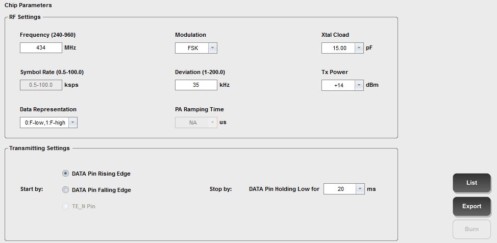
16 Appendix II CMT2119A configuration screenshot
RF67 Communication Example
 RF67 Communication Example AN-2004 VER1.1 This chapter will guide the user to carry out RFM67 and RFM219 transmitting and receiving communication experiment through HopeDuino, at the same time display
RF69 Communication Example
 RF69 Communication Example AN-2001 VER1.1 This chapter will guide the user to carry out a pair of RF69 transmitting and receiving communication experiment through HopeDuino. RF69 is a main push wireless
LoRa Communication Example
 LoRa Communication Example AN-2003 VER1.1 This chapter will guide the user to carry out a pair of LoRa transmitting and receiving communication experiment through HopeDuino. LoRa is a unique spread spectrum
CMT2110A/2210A One-Way RF Link Development Kits User s Guide
 AN103 CMT2110A/2210A One-Way RF Link Development Kits User s Guide Introduction CMT2110A/2210A One-Way RF Link Development Kits (Development Kits) are a set of the hardware and software tools designed
DCB1M - Transceiver for Powerline Communication
 Preliminary Description DCB1M - Transceiver for Powerline Communication The information in this data sheet is preliminary and may be changed without notice. 1. General The DCB1M is an innovative technology
ArduCAM-M-2MP Camera Shield
 33275-MP ArduCAM-M-2MP Camera Shield 2MP SPI Camera Hardware Application Note Rev 1.0, Mar 2015 33275-MP ArduCAM-M-2MP Hardware Application Note Table of Contents 1 Introduction... 2 2 Typical Wiring...
Device: MOD This document Version: 1.0. Matches module version: v3 [29 June 2016] Date: 23 October 2017
![Device: MOD This document Version: 1.0. Matches module version: v3 [29 June 2016] Date: 23 October 2017](/thumbs/80/81580515.jpg "Device: MOD This document Version: 1.0. Matches module version: v3 [29 June 2016] Date: 23 October 2017") Device: MOD-1025 This document Version: 1.0 Matches module version: v3 [29 June 2016] Date: 23 October 2017 Description: UART (async serial) to I2C adapter module MOD-1025 v3 datasheet Page 2 Contents
Device: MOD-1025 This document Version: 1.0 Matches module version: v3 [29 June 2016] Date: 23 October 2017 Description: UART (async serial) to I2C adapter module MOD-1025 v3 datasheet Page 2 Contents
CMT2300A FIFO and Packet Format Usage Guideline
 AN143 CMT23A FIFO and Packet Format Usage Guideline Summary This article describes the CMT23A FIFO, packet format and the working principle of the interrupt system. When the article introduces the contents
Product Family Specification
 Doc.Nr. 8260800.06 Product Family Specification Absolute pressure sensor SCP1000-D01 SCP1000-D11 Note: Reader is advised to notice that this Product Family Specification applies to SCP1000 version which
EM RF Transceiver. - Framer and Digital Interface Control
 Application Notes EM198810 RF Transceiver - Framer and igital Interface Control Introduction This Application Note describes the detailed packet handling details pertaining to the Elan EM198810. For the
Arduino Uno R3 INTRODUCTION
 Arduino Uno R3 INTRODUCTION Arduino is used for building different types of electronic circuits easily using of both a physical programmable circuit board usually microcontroller and piece of code running
ED1021 I/O Expander with UART interface & analog inputs
 Preliminary Highlights 4.5V 5.5V power supply range. 12 GPIOs. Up to 40mA maximum current in each output except GPIO8 (up to a total device current of 175mA). Most GPIOs can be an input to a 10bit ADC.
USER GUIDE EDBG. Description
 USER GUIDE EDBG Description The Atmel Embedded Debugger (EDBG) is an onboard debugger for integration into development kits with Atmel MCUs. In addition to programming and debugging support through Atmel
Hello, and welcome to this presentation of the STM32 Universal Synchronous/Asynchronous Receiver/Transmitter Interface. It covers the main features
 Hello, and welcome to this presentation of the STM32 Universal Synchronous/Asynchronous Receiver/Transmitter Interface. It covers the main features of this USART interface, which is widely used for serial
JMY505G User's Manual
 JMY505G User's Manual (Revision 3.42) Jinmuyu Electronics Co. LTD 2011/6/28 Please read this manual carefully before using. If any problem, please mail to: jinmuyu@vip.sina.com Contents 1 Product introduction...
CAN / RS485. Product Description. Technical Reference Note. Interface Adapter. Special Features
 CAN / Interface Adapter For SHP Series Total Power: < 1 Watts Input Voltage: 5V Internal Outputs: CAN,, USB, I 2 C Special Features Input Protocols: 1) using Modbus 2) CAN using modified Modbus Output
EDBG. Description. Programmers and Debuggers USER GUIDE
 Programmers and Debuggers EDBG USER GUIDE Description The Atmel Embedded Debugger (EDBG) is an onboard debugger for integration into development kits with Atmel MCUs. In addition to programming and debugging
TPMC810. Isolated 2x CAN Bus. Version 1.1. User Manual. Issue June 2009
 The Embedded I/O Company TPMC810 Isolated 2x CAN Bus Version 1.1 User Manual Issue 1.1.6 June 2009 TEWS TECHNOLOGIES GmbH Am Bahnhof 7 25469 Halstenbek / Germany Phone: +49-(0)4101-4058-0 Fax: +49-(0)4101-4058-19
CN310 Microprocessor Systems Design
 CN310 Microprocessor Systems Design Microcontroller Nawin Somyat Department of Electrical and Computer Engineering Thammasat University Outline Course Contents 1 Introduction 2 Simple Computer 3 Microprocessor
I 2 C Application Note in Protocol B
 I 2 C Application Note in Protocol B Description This document is a reference for a possible coding method to achieve pressure, temperature, and status for SMI part readings using I 2 C. This SMI Protocol
ED1021 I/O Expander with UART interface & analog inputs
 Preliminary Highlights 2.7V 5V power supply range. 12 GPIOs. Up to 40mA maximum current in each output except GPIO8 (up to a total device current of 175mA). Most GPIOs can be an input to a 10bit ADC. Simple
Design and development of embedded systems for the Internet of Things (IoT) Fabio Angeletti Fabrizio Gattuso
 Fabio Angeletti Fabrizio Gattuso") Design and development of embedded systems for the Internet of Things (IoT) Fabio Angeletti Fabrizio Gattuso Microcontroller It is essentially a small computer on a chip Like any computer, it has memory,
Design and development of embedded systems for the Internet of Things (IoT) Fabio Angeletti Fabrizio Gattuso Microcontroller It is essentially a small computer on a chip Like any computer, it has memory,
SH1030 Rev Introduction. Ultra low power DASH7 Arduino Shield Modem. Applications. Description. 868 MHz. Features
 SH1030 Rev. 1.2 Applications Wireless sensor network Data acquisition equipment Security systems Industrial monitor and control Internet of things (IoT) Ultra low power DASH7 Arduino Shield Modem 868 MHz
Freescale Semiconductor, I
 nc. Application Note Rev. 0, 4/2004 Software Drivers for Tango3 RF Transmitter and Romeo2 RF Receiver ICs By John Logan 8/16-Bit Division East Kilbride, Scotland Introduction This application note describes
ECE251: Thursday November 8
 ECE251: Thursday November 8 Universal Asynchronous Receiver & Transmitter Text Chapter 22, Sections 22.1.1-22.1.4-read carefully TM4C Data Sheet Section 14-no need to read this A key topic but not a lab
SRF02 Ultrasonic range finder Technical Specification
 SRF02 Ultrasonic range finder Technical Specification I2C Mode For Serial mode click here I2C Communication To use the SRF02 in I2C mode, make sure nothing is connected to the mode pin, it must be left
COMMUNICATION MODBUS PROTOCOL
 COMMUNICATION MODBUS PROTOCOL CE4DMID31 / CE4DMID21 CONTO D4 Pd MID PR123 20/10/2016 Pag. 1/9 Contents 1.0 ABSTRACT... 2 2.0 DATA MESSAGE DESCRIPTION... 3 2.1 Parameters description... 3 2.2 Data format...
OEM API Specification
 OEM API Specification For Wasatch Photonics OEM Spectrometers WasatchDevices.com Revised 2016-08-26 Page 1 Revision Log Revision Date By Reason 1.0 2016-08-29 J. Traud Initial Release Contents General
COMMUNICATION MODBUS PROTOCOL
 COMMUNICATION MODBUS PROTOCOL CE4DT36 CONTO D4 Pd (3-single phase) PR134 20/10/2016 Pag. 1/11 Contents 1.0 ABSTRACT... 2 2.0 DATA MESSAGE DESCRIPTION... 3 2.1 Parameters description... 3 2.2 Data format...
Color 7 click. PID: MIKROE 3062 Weight: 19 g
 Color 7 click PID: MIKROE 3062 Weight: 19 g Color 7 click is a very accurate color sensing Click board which features the TCS3472 color light to digital converter with IR filter, from ams. It contains
Pedometer 3 Click. PID: MIKROE 3259 Weight: 24 g
 Pedometer 3 Click PID: MIKROE 3259 Weight: 24 g The Pedometer 3 click is a tri-axis acceleration sensing Click board utilizing the KX126-1063. An advanced three-axis acceleration sensor, the KX126-1063
DMTME Multimeters. Communication protocol. Technical specification V1.2 ABB
 DMTME Multimeters Communication protocol ABB 1 Setting up DMTME serial communication.3 1.1 Serial network ID programming...3 1.2 RS-485 communication interface...3 1.3 Serial line connection...3 2 Communication
WM1030 Rev Introduction. Ultra low power DASH7 Modem. Applications. Description. 868 / 915 MHz. Features. WIZZILAB Technical datasheet 1/10
 WM1030 Rev. 1.2 Applications Wireless sensor network Data acquisition equipment Security systems Industrial monitor and control Internet of things (IoT) Ultra low power DASH7 Modem 868 / 915 MHz 1 Introduction
USER GUIDE. Wireless Production Test Reference Protocol Specification Document. Atmel MCU Wireless. Description
 USER GUIDE Wireless Production Test Reference Protocol Specification Document Atmel MCU Wireless Description This document explains the serial protocol used for communication between various blocks of
M2M/DMTME Instruments Communication protocol. Technical specification V.2.1 2CSG445011D0201
 M2M/DMTME Instruments Communication protocol 2CSG445011D0201 1 Setting up M2M/DMTME serial communication... 3 1.1 Serial network ID programming... 3 1.2 RS-485 communication interface... 3 1.3 Serial line
User s Guide SX SKA ADVANCED COMMUNICATIONS & SENSING SX SKA. User s Guide: Advanced Mode. Revision 0.1 March Semtech Corp.
 : Advanced Mode 1 Table of Contents 1 Introduction... 4 2 Getting Started... 5 2.1 Kit Contents... 5 2.2 Installation... 5 3 Hardware Description... 6 3.1 SX1230SKA Overview... 6 3.2 SX1211SKA Overview...
JMY504M User's Manual
 JMY504M User's Manual (Revision 3.42) Jinmuyu Electronics Co. LTD 2011/6/28 Please read this manual carefully before using. If any problem, please mail to: Jinmuyu@vip.sina.com Contents 1 Product introduction...
1. Implemented CM11 protocol
 1. Implemented CM11 protocol 1.1. Housecodes and Device Codes. The housecodes and device codes range from A to P and 1 to 16 respectively although they do not follow a binary sequence. The encoding format
AN4 QCA7000 SPI / UART Protocol
 AN4 QCA7000 SPI / UART Protocol I2SE GmbH: Christian Aurich, Stefan Wahren June 14, 2018 1/11 CONTENTS CONTENTS Contents 1 Revisions 3 2 Introduction 3 3 SPI Physical Layer 3 4 UART Physical Layer 3 5
Digital UART Product Specification
 Copyright 2016 Zilog, Inc. All rights reserved. www.zilog.com DIgital UART ii Warning: DO NOT USE THIS PRODUCT IN LIFE SUPPORT SYSTEMS. LIFE SUPPORT POLICY ZILOG'S PRODUCTS ARE NOT AUTHORIZED FOR USE AS
RFT(Robotous Force/Torque Sensor) Series
 Series") RFT(Robotous Force/Torque Sensor) Series Installation and Operation Manual REVISION 1.1 1 Contents 1. Caution 4 1.1. Notices 4 1.2. Warning 4 2. Installation 5 2.1. Overview 5 2.2. Power Supply Specifications
RFT(Robotous Force/Torque Sensor) Series Installation and Operation Manual REVISION 1.1 1 Contents 1. Caution 4 1.1. Notices 4 1.2. Warning 4 2. Installation 5 2.1. Overview 5 2.2. Power Supply Specifications
SquareWear Programming Reference 1.0 Oct 10, 2012
 Content: 1. Overview 2. Basic Data Types 3. Pin Functions 4. main() and initsquarewear() 5. Digital Input/Output 6. Analog Input/PWM Output 7. Timing, Delay, Reset, and Sleep 8. USB Serial Functions 9.
KT403A Datasheet(Part)
") Datasheet(Part) Content 1. Chip Instruction 3 1.1 Hardware parameters 3 1.2 Pin description 4 2. Serial communication 5 2.1 The communication format 5 2.2 Commands(CMD) 5 2.3 Serial communication instructions
Datasheet(Part) Content 1. Chip Instruction 3 1.1 Hardware parameters 3 1.2 Pin description 4 2. Serial communication 5 2.1 The communication format 5 2.2 Commands(CMD) 5 2.3 Serial communication instructions
Wireless-Tag WT51822-S4AT
 Description: WT51822-S4AT is a high performance,low power radio transmit and receive system module use Nordic BLE 4.1 nrf51822 as the controller chips. It has the smallest volume package in the industry,
WiMOD LR Base Host Controller Interface
 WiMOD LR Base Host Controller Interface Specification Version 1.7 Document ID: 4100/40140/0062 IMST GmbH Carl-Friedrich-Gauß-Str. 2-4 47475 KAMP-LINTFORT GERMANY Introduction Document Information File
WiMOD LR Base Plus Host Controller Interface
 WiMOD LR Base Plus Host Controller Interface Specification Version 1.2 Document ID: 4000/40140/0125 IMST GmbH Carl-Friedrich-Gauß-Str. 2-4 47475 KAMP-LINTFORT GERMANY Introduction Document Information
Protocol of data exchange with modem via USB interface Version
 Protocol of data exchange with modem via USB interface Version 2017.12.19 - Modem connects to USB-host as USB device of CDC class (virtual COM port in Windows, ttyusb or ttyacm in Linux) - Because real
CTT MODBUS-RTU COMMUNICATION PROTOCOL TEMPERATURE MONITOR DEVICE
 INSTRUCTION MANUAL IM149-U v0.92 CTT MODBUS-RTU COMMUNICATION PROTOCOL TEMPERATURE MONITOR DEVICE Firmware version: v3.0 or higher MODBUS PROTOCOL Modbus is a master-slave communication protocol able to
Logosol Joystick Node LS-731
 Features 2 and 3 axis models Travel ±20 deg Non contact hall effect joystick Mechanical MTBF 15,000,000 cycles 3 pushbuttons Up to 2 stick pushbuttons 8 LEDs Member of Logosol s distributed motion control
VORAGO VA108x0 I 2 C programming application note
 AN1208 VORAGO VA108x0 I 2 C programming application note MARCH 14, 2017 Version 1.1 VA10800/VA10820 Abstract There are hundreds of peripheral devices utilizing the I 2 C protocol. Most of these require
TPMC310. Conduction Cooled PMC Isolated 2 x CAN Bus. Version 1.1. User Manual. Issue June 2014
 The Embedded I/O Company TPMC310 Conduction Cooled PMC Isolated 2 x CAN Bus Version 1.1 User Manual Issue 1.1.6 June 2014 TEWS TECHNOLOGIES GmbH Am Bahnhof 7 25469 Halstenbek, Germany Phone: +49 (0) 4101
1. General Description
 1. General Description HPTZ01X (HPTZ01-TTL,HPTZ01P-TTL)Serial ZigBee module is development designed by Ember ZigBee chip EM35x. It is a module base on IEEE 802.15.4-2003 standard for the 2.4G ISM band.
MSP430F149 P3.4/UTXD0 P3.5/URXD0 P1.5 P1.6 P1.7 MSP430F149 P1.0 P5.4 P5.3 P5.2 P5.1. Figure B-1. BSL Replicator Block Diagram
 Appendix B Appendix B MSP430 BSL Replicator Author: Greg Morton, MSP430 Applications B.1 BSL Replicator Overview The BSL Replicator application, executing on a host MSP430F149 device, uses the BSL protocol
WiMOD LR Base Host Controller Interface
 WiMOD LR Base Host Controller Interface Specification Version 1.10 Document ID: 4100/40140/0062 IMST GmbH Carl-Friedrich-Gauß-Str. 2-4 47475 KAMP-LINTFORT GERMANY Introduction Document Information File
Keywords: CRC, CRC-7, cyclic redundancy check, industrial output, PLC, programmable logic controller, C code, CRC generation, microprocessor, switch
 Keywords: CRC, CRC-7, cyclic redundancy check, industrial output, PLC, programmable logic controller, C code, CRC generation, microprocessor, switch APPLICATION NOTE 6002 CRC PROGRAMMING FOR THE MAX14900E
Each I2C master has 8-deep transmit and receive FIFOs for efficient data handling. SPI to Dual I2C Masters. Registers
 February 205 Introduction Reference Design RD73 I2C and SPI are the two widely used bus protocols in today s embedded systems. The I2C bus has a minimum pin count requirement and therefore a smaller footprint
keyestudio Keyestudio MEGA 2560 R3 Board
 Keyestudio MEGA 2560 R3 Board Introduction: Keyestudio Mega 2560 R3 is a microcontroller board based on the ATMEGA2560-16AU, fully compatible with ARDUINO MEGA 2560 REV3. It has 54 digital input/output
PIC-I/O Multifunction I/O Controller
 J R KERR AUTOMATION ENGINEERING PIC-I/O Multifunction I/O Controller The PIC-I/O multifunction I/O controller is compatible with the PIC-SERVO and PIC-STEP motor control modules and provides the following
DL-LN3X Series 2.4G Ad-hoc Network Wireless Communication Module
 DL-LN3X Series 2.4G Ad-hoc Network Wireless Communication Module DL-LN3X series module is the wireless communication module independently developed. The module is designed specifically for the applications
Dual Serial Shield User Manual
 Dual Serial Shield User Manual PN: 2050 Berkshire Products, Inc. Phone: 770-271-0088 http://www.bkp-store.com/ Rev: 1.00 Copyright 2013 Table of Contents 1 Introduction... 2 1.1 XB compatibility... 2 2
< W3150A+ / W5100 Application Note for SPI >
 < W3150A+ / W5100 Application Note for SPI > Introduction This application note describes how to set up the SPI in W3150A+ or W5100. Both the W3150A+ and W5100 have same architecture. W5100 is operated
Version. Table of Contents
 NAP Protocol 1.0 Version Version Date By Comment v1.0 24.01.2011 JP Release version of NAP documentation. Table of Contents 1 Basic concepts...3 1.1 Usage info...3 1.2 Length byte...3 1.3 Literal characters...4
Product Brief. Model: TLM922S-P01A. Ver.1.0
 Product Brief Model: TLM922S-P01A Ver.1.0 1 Index 1. Overview... 3 2. Product Features... 3 3. Application... 4 4. Product Specifications... 4 5. PIN Definition... 6 6. PCB Dimension... 7 7. Pin Configuration...
IP71X Ethernet Interface Communication Protocol V1.6
 IP71X Ethernet Interface Communication Protocol V1.6 IP71X series Ethernet singlechip interface module connects with computer terminal; the computer initiates communication, and computer terminal is communication
COMMUNICATION MODBUS PROTOCOL
 COMMUNICATION MODBUS PROTOCOL BOZZA_V04 Conto D6-Pd 05/12/2017 Pag. 1/15 CONTENTS 1.0 ABSTRACT... 2 2.0 DATA MESSAGE DESCRIPTION... 3 2.1 Parameters description... 3 2.2 Data format... 4 2.3 Description
 Features 2.4 GHz Carrier Frequency RS232 UART interface with variable baud rate Input supply voltage: 5V to 12V 255 possible Channels frequencies (0 to 255) Programmable Device Address (255 per channel)
Tel: Fax:
 /****************************************************************************** Title: RFM22 transmitter demo program Current version: V1.2 Function: Package send Demo Processor PIC16F690 DIP-20 Clock:
Emulating I2C Bus Master by using FlexIO
 Freescale Semiconductor, Inc. Document Number: AN5133 Application Notes Rev. 0, 06/2015 Emulating I2C Bus Master by using FlexIO 1. Introduction This application note lists the steps to use the FlexIO
DFRobot BLE4.1 Module SKU: TEL0120
 DFRobot BLE4.1 Module SKU: TEL0120 Introduction BLE4.1 Module is DFRobot newly developed Bluetooth 4.1 transmission module, adhering to the same usage of Bluno, and increasing the star network function,
ARDUINO MICRO WITHOUT HEADERS Code: A000093
 ARDUINO MICRO WITHOUT HEADERS Code: A000093 Arduino Micro is the smallest board of the family, easy to integrate it in everyday objects to make them interactive. The Micro is based on the ATmega32U4 microcontroller
Hardware interface and protocol of data exchange with mobile beacon via USB, UART and SPI interfaces.
 Hardware interface and protocol of data exchange with mobile beacon via USB, UART and SPI interfaces. Version 2016.03.07 Valid for firmware v4.07 and newer To get location data from mobile beacon (hedgehog),
QBridge. I2C, SPI, CAN Control Software User s Manual. Date: Rev 1.3
 QBridge I2C, SPI, CAN Control Software User s Manual Date: 9-10-2005 Rev 1.3 1. Introduction...1 1.1. What QBridge can do?... 1 1.2. Disclaimer... 1 1.3. Operational Format... 1 1.4. QBridge-V2... 1 2.
ICN12. I2C to UART Bridge, ADC,DAC and I/O
 Firmware version 1.4 Introduction ICN12 I2C to UART Bridge, ADC,DAC and I/O This is an I2C to UART bridge, designed to give an extra UART to a microcontroller when only I2C is available. It is an I2C device
ZigBee Compliant Platform 2.4G RF Low Power Transceiver Module for IEEE Standard. DATA SHEET Version B
 ZMD400-A01 ZigBee Compliant Platform 2.4G RF Low Power Transceiver Module for IEEE 802.15.4 Standard DATA SHEET Version B Quan International Co., Ltd., ZMD400 Features Fully compliant 802.15.4 Standard
DIGITAL HUMIDITY SENSOR HYT-131
 Rights reserved for change in technical data! B+B Thermo-Technik GmbH Postfach 1748 D-78158 Donaueschingen Phone: +49 771 8316-622 Fax: +49 771 8316-629 DIGITAL HUMIDITY SENSOR 1. Features - On-Chip humidity
TPMC Channel Isolated Serial Interface RS232. Version 1.0. User Manual. Issue August 2017
 The Embedded I/O Company TPMC860 4 Channel Isolated Serial Interface RS232 Version 1.0 User Manual Issue 1.0.4 August 2017 TEWS TECHNOLOGIES GmbH Am Bahnhof 7 25469 Halstenbek, Germany Phone: +49 (0) 4101
Using the FADC250 Module (V1C - 5/5/14)
") Using the FADC250 Module (V1C - 5/5/14) 1.1 Controlling the Module Communication with the module is by standard VME bus protocols. All registers and memory locations are defined to be 4-byte entities.
Using the FADC250 Module (V1C - 5/5/14) 1.1 Controlling the Module Communication with the module is by standard VME bus protocols. All registers and memory locations are defined to be 4-byte entities.
Read section 8 of this document for detailed instructions on how to use this interface spec with LibUSB For OSX
 CP2130 INTERFACE SPECIFICATION 1. Introduction The Silicon Labs CP2130 USB-to-SPI bridge is a device that communicates over the Universal Serial Bus (USB) using vendor-specific control and bulk transfers
The IIC interface based on ATmega8 realizes the applications of PS/2 keyboard/mouse in the system
 Available online at www.sciencedirect.com Procedia Engineering 16 (2011 ) 673 678 International Workshop on Automobile, Power and Energy Engineering The IIC interface based on ATmega8 realizes the applications
Product Specification
 Product Specification Features Amp ed RF, Inc. Description 15mm x 27mm The added class 1 power, +18dBm, of the BT-11, gives this module one of the best ranges in the industry. It s completely pin compatible
TPMC Channel Isolated Serial Interface RS422/RS485. Version 1.0. User Manual. Issue July 2009
 The Embedded I/O Company TPMC861 4 Channel Isolated Serial Interface RS422/RS485 Version 1.0 User Manual Issue 1.0.3 July 2009 TEWS TECHNOLOGIES GmbH Am Bahnhof 7 25469 Halstenbek, Germany Phone: +49 (0)
RF4431 wireless transceiver module
 RF4431 wireless transceiver module 1. Description RF4431 adopts Silicon Labs Si4431 RF chip, which is a highly integrated wireless ISM band transceiver chip. Extremely high receive sensitivity (-121 dbm)
Accel 5 click. PID: MIKROE 3149 Weight: 24 g
 Accel 5 click PID: MIKROE 3149 Weight: 24 g Accel 5 click features an ultra-low power triaxial accelerometer sensor, labeled as the BMA400. This Click board allows linear motion and gravitational force
Getting Started. With the Y-Lynx Starter Kit. Transce iver. of the XEMICS XE1205TrueRF tm. Y-Lynx web:
 Getting Started With the Y-Lynx Starter Kit of the XEMICS XE1205TrueRF tm Transce iver Y-Lynx e-mail: info@y-lynx.com web: www.y.lynx.com Getting S tart ed with the Y-L ynx XE1 205TrueRF tm Start er Kit
PCI-4IPM Revision C. Second Generation Intelligent IP Carrier for PCI Systems Up to Four IndustryPack Modules Dual Ported SRAM, Bus Master DMA
 PCI-4IPM Revision C Second Generation Intelligent IP Carrier for PCI Systems Up to Four IndustryPack Modules Dual Ported SRAM, Bus Master DMA REFERENCE MANUAL 781-21-000-4000 Version 2.1 April 2003 ALPHI
Hello, and welcome to this presentation of the STM32 I²C interface. It covers the main features of this communication interface, which is widely used
 Hello, and welcome to this presentation of the STM32 I²C interface. It covers the main features of this communication interface, which is widely used to connect devices such as microcontrollers, sensors,
Concepts of Serial Communication
 Section 6. Serial Communication Communication Using Serial Interfaces: UART and SPI Concepts of Serial Communication Limitations of Parallel Bus Clock skew becomes a serious issue for high speed and long
Appendix) Specifications of Monitor & Control Rev. 4.0 July 13, 2016
 Specifications of Monitor & Control Rev. 4.0 July 13, 2016") Specifications of Monitor & Control July 13, 2016 1. Interface Specifications 1-1. FSK Communication M&C (1) Physical Interface IF Connector: N-type or F-type, female Combine with IF signal and 10MHz Reference
Specifications of Monitor & Control July 13, 2016 1. Interface Specifications 1-1. FSK Communication M&C (1) Physical Interface IF Connector: N-type or F-type, female Combine with IF signal and 10MHz Reference
Data sheet Wireless UART firmware version 4
 Data sheet Wireless UART firmware version 4 BLUETOOTH is a trademark owned by Bluetooth SIG, Inc., U.S.A. and licensed to Free2move Rev: 05 December 2006 Table of contents 1 GENERAL INFORMATION...4 1.1
Kinetis Bootloader to Update Multiple Devices in a Field Bus Network
 Freescale Semiconductor, Inc. Document Number: AN5204 Application Note Rev. 0, 01/2016 Kinetis Bootloader to Update Multiple Devices in a Field Bus Network 1. Introduction This application note describes
LM780 Bluetooth Module with IC Antenna
 Bluetooth Module with C Antenna Revised 8/NO/2017 Features Bluetooth v2.0 / v2.1 specification 26.92mm x 15.20mm x 2.0mm 4 dbm Tx Output Power (Class 2) SMT Side and Bottom Pads for easy production Low
FN-BC04 MP3 Sound Module with 10W Amplifier. User s Manual
 User s Manual V1.1 Contents 1. Overviews.....2 1.1. Brief introduction... 2 1.2. Features. 2 1.3. Technical parameters... 2 2. Connections......2 3. Button Control Mode......3 3.1. Trigger Mode Selection...3
CE4DMID01 COMMUNICATION PROTOCOL CONTENTS 1.0 INTRODUCTION
 11/11/2011 Pagina 1 di 11 ELECTRICITY ENERGY METER FIRMWARE 1.3 CE4DMID01 COMMUNICATION PROTOCOL CONTENTS 1.0 INTRODUCTION 2.0 DATA MESSAGE DESCRIPTION 2.1 Data field description 2.2 Data format 2.3 Description
Remote Keyless Entry In a Body Controller Unit Application
 38 Petr Cholasta Remote Keyless Entry In a Body Controller Unit Application Many of us know this situation. When we leave the car, with a single click of a remote control we lock and secure it until we
HZX N03 Bluetooth 4.0 Low Energy Module Datasheet
 HZX-51822-16N03 Bluetooth 4.0 Low Energy Module Datasheet SHEN ZHEN HUAZHIXIN TECHNOLOGY LTD 2017.7 NAME : Bluetooth 4.0 Low Energy Module MODEL NO. : HZX-51822-16N03 VERSION : V1.0 1.Revision History
F28335 I2C MODULE v1.1
 1 F28335 I2C MODULE v1.1 Abstract This document describes how to configure for I2C module of F28335. 2 Table of Contents 1. Overview... 3 2. Configuration details... 3 3. Reference... 7 3 1. Overview Step
PL1167. Low Power High Performance Single Chip 2.4GHz Transceiver. Product Description: Key Features: Applications: Pin Configuration:
 Low Power High Performance Single Chip 2.4GHz Transceiver Product Description: is a piece of true low power high performance single chip 2.4GHz transceiver, which is designed for operation in the world
RFIC TX/RX Configuration
 RFIC TX/RX Configuration RFIC TX/RX Configuration 01/19/17 1 of 10 www.murata.com RXC101 Configuration When the RXC101 is configured in microcontroller mode, data can be received in three ways; directly
LCM-160. Low-Power Embedded Communication Module. Rev. Dec 26, LCM-160 Datasheet. Website:
 LCM-160 Low-Power Embedded Communication Module Rev. Dec 26, 2017 LCM-160 Datasheet Email: yacer@yacer.cn Website: www.yacer.cn 1 Overview... 3 1.1 Introduction... 3 1.2 Features... 3 1.3 Applications...
Approved by: Date CET Initials Name Justification :20:12 NTJ Niels Thybo Johansen
 Instruction Selection Guideline Document No.: INS10027 Version: 6 Description: This document introduces the ZW0201, and ZW0301 Single Chip based families, and suggests which module to choose for a given