4. Error correction and link control. Contents
|
|
|
- Wesley Woods
- 5 years ago
- Views:
Transcription
1 //2 4. Error correction and link control Contents a. Types of errors b. Error detection and correction c. Flow control d. Error control
2 //2 a. Types of errors Data can be corrupted during transmission. Some applications require that errors be detected and corrected. 2
3 //2 In a single-bit error, only bit in the data unit has changed. Single-bit error 3
4 //2 A burst error means that 2 or more bits in the data unit have changed. Burst error of length 8 4
5 //2 To detect or correct errors, we need to send extra (redundant) bits with data. b. Error detection and correction 5
6 //2 Process of error detection in block coding Structure of encoder and decoder in error correction 6
7 //2 c. Flow control Flow Control Ensure sending entity does not overwhelm receiving entity by preventing buffer overflow influenced by: transmission time time taken to emit all bits into medium propagation time time for a bit to traverse the link assume here no errors but varying delays 7
8 //2 Model of Frame Transmission Stop and Wait source transmits frame destination receives frame and replies with acknowledgement (ACK) source waits for ACK before sending next destination can stop flow by not send ACK This procedure works well for a few large frames Stop and wait becomes inadequate if large block of data is split into small frames 8
9 //2 Stop and Wait Link Utilization Sliding Windows Flow Control Allows multiple numbered frames to be in transit receiver has buffer W long transmitter sends up to W frames without ACK ACK includes number of next frame expected Sequence number is bounded by size of field (k) frames are numbered modulo 2 k giving max window size of up to 2 k Receiver can ack frames without permitting further transmission (Receive Not Ready) Must send a normal acknowledge to resume If have full-duplex link, can piggyback ACks 9
10 //2 d. Error control Error Control. Detection and correction of errors such as: lost frames damaged frames Common techniques use: error detection positive acknowledgment retransmission after timeout negative acknowledgement & retransmission
11 //2 Automatic Repeat Request (ARQ) Collective name for such error control mechanisms, including: stop and wait go back N selective reject (selective retransmission) Stop and Wait Source transmits single frame wait for ACK if received frame damaged, discard it transmitter has timeout if no ACK within timeout, retransmit if ACK damaged,transmitter d will not recognize it transmitter will retransmit receive gets two copies of frame use alternate numbering and ACK / ACK
12 //2 Stop and Wait Example with both types of errors pros and cons simple inefficient Go Back N Based on sliding window if no error, ACK as usual Use window to control number of outstanding frames If error, reply with rejection discard that frame and all future frames until error frame received correctly transmitter must go back and retransmit that frame and all subsequent frames 2
13 //2 Damaged Frame Go Back N - Handling error in frame i so receiver rejects frame i transmitter retransmits frames from frame i Lost Frame frame i lost and either transmitter sends i+ and receiver gets frame i+ out of seq and rejects frame i or transmitter times out and send ACK with P bit set which receiver responds to with ACK i transmitter then retransmits frames from i Go Back N - Handling Damaged Acknowledgement receiver gets frame i,, sends ack (i+) which is lost acks are cumulative, so next ack (i+n) may arrive before transmitter times out on frame i if transmitter times out, it sends ack with P bit set can be repeated a number of times before a reset procedure is initiated Damaged Rejection reject for damaged frame is lost handled as for lost frame when transmitter times out 3
14 //2 Selective Reject Also called selective retransmission Only rejected frames are retransmitted Subsequent frames are accepted by the receiver and buffered Minimizes retransmission Receiver must maintain large enough buffer More complex logic in transmitter Hence less widely used Useful for satellite links with long propagation delays Go Back N vs Selective Reject 4
15 //2 Error control There are several error detection methods, and their application depends on the type of errors encountered on the line. There are random -bit or 2-bit errors, and there are burst errors. Error control PARITY CRC VRC LRC CHECKSUM 5
 is added to each character before being sent.")
16 //2 Error control by parity This method identifies only errors in asynchronous transmissions and byte-oriented protocols. In this method, an extra bit (the parity bit) is added to each character before being sent. The receiver performs an opposite operation, and if: The result is the same, it is assumed that there has been no error. If it differs, it is assumed that t there has been an error. However, if there are two errors, this character may go through with these errors undetected. Encoder and decoder for simple parity-check code 6
17 //2 A simple parity-check code can detect an odd number of errors. Checksum When character blocks are sent, there is an increased possibility that a character and, thus, the block, may contain an error. In this method, characters are placed in a 2D block. A parity bit is added to each character, using the parity error check method. A parity bit is also added for each bit position in all characters. In other words, an additional character is created, in which its i-th bit is the parity bit for the i-th bits of the characters. This may be expressed with an OR-EX operation. 7
18 //2 Checksum So the parity bit at the end of each character is the row parity bit and is: R j = b j b 2j... b nj where: R j = parity bit of the j-th character B ij = i-th bit of the j-th character n = number of bits in a character Parity bits generated at the end of each character are known as Vertical Redundancy Check VRC. Checksum There is a formula to generate the parity-check character: Ci = b i b i2... b in where: C i = i-th bit of the parity-check character m = number of characters in a frame This character is called Longitudinal Redundancy Check (LRC) 8
19 //2 Checksum Cyclic redundancy check - CRC A more powerful error control technique is the Cyclic Redundancy Check (CRC). Given a k-bit-long message or frame, the sender generates a sequence of n bits, known as Frame Check Sequence (FCS), in such a way that the resulting frame, consisting of k + n bits, is exactly divisible by a predetermined number. 9
20 //2 Cyclic redundancy check - CRC The receiver divides the incoming frame by the same predetermined number, and, if there is no remainder, it is assumed that the frame has arrived without errors. This procedure may be applied in several ways: using modulo-2 arithmetic, polynomials and OR-EX gates with displacement records. Cyclic redundancy check - CRC We will work with binary numbers and modulo-2 arithmetic. Modulo-2 arithmetic uses the binary sum with no carries as an OR-EX gate operation. For example: + x 2
21 //2 Cyclic redundancy check - CRC Now we define: T = (k+n) bit frame to be sent with n < k M = k-bit message. They are the first bits of frame T F = Frame Check Sequence (FCS). They are the last bits of frame T P = n+ bit pattern. This is the aforementioned predetermined divisor. Cyclic redundancy check - CRC The desired outcome is that the division between frame T to be sent and the n + bit pattern will have no remainder. So: T = 2 n M + F () That is, by multiplying M by 2 n, n bits will be displaced to the left and the displaced bits will be completed with s. The addition of F gives us the concatenation of M and F, which results in T. 2
22 //2 Cyclic redundancy check - CRC Now we want T to be exactly divisible by P. If we divide 2 n M by P: 2 n M = Q + R (2) P P we obtain a quotient and a remainder. Since it is a binary division, the remainder is always one bit less than the divisor. We use this remainder as our FCS. So: T = 2 n M + R (3) Cyclic redundancy check - CRC Now we will show that R meets our condition. Let us consider: T = 2 n M + R = 2 n M +R (4) P P P P By substituting equation (2) in (4), we have that: T = Q + R +R (5) P P P 22
23 //2 Cyclic redundancy check - CRC Any binary number added to itself in modulo 2 is equal to zero. So: T = Q + R + R = Q P P It thus demonstrates that there is no remainder, so T is exactly divisible by P. We thus generate the FCS. 2 n M is divided by P and the remainder is used as the FCS. In the receiving side, the receiver will divide T by P, and if there is no remainder, it means that the frame has been received with no errors. Example of cyclic redundancy check Given: Message M = ( bits) Pattern P = (6 bits) FCS (R) = to be calculated (5 bits) The message is multiplied by 2 5, resulting in: = 2 n M = 2 5 M 23
24 //2 Example of cyclic redundancy check This product 2 5 M is divided by P: 2 5 M P Q R Example of cyclic redundancy check The remainder is added to the value of 2 n M to obtain: T =, which is sent. If there are no errors, the receiver will receive T intact. 24
25 //2 Example of cyclic redundancy check The frame received is divided by P: Cyclic redundancy check - CRC Since there is no remainder, it is assumed that the frame received has no errors. There are 4 versions of CRC broadly used: 25
26 //2 Block line codes A block code requires that a message be partitioned in bit blocks. A data word is a block that has k bits. Therefore, the number of data words is: 2 k Data words are coded within code words. Each code word is a block of n bits. The possible number of code words is 2 n, but only 2 k are used and transmitted. The additional n-k bits are called parity-check bits. Systematic code words Redundancycheck bits Message n-k digits K digits (data word) n digits it = code word 26
27 //2 Code rate The code rate r c is defined as: k r c = n The code annotation is (n, k). For example, a code containing a 4-bit data word in a 7-bit code word will be a code: (k = 4, n =7 7, ) Its code rate will be: r c = 4/7 Repetition code A repetition code has some of the properties of the block code. In a repetition code, each bit is a data word: K = For a redundancy coding n, the encoder output will be n bits identical to the input bit. Considering the case of: n = 3 If is sent, the output is the code word If is sent, the code word will be 27
28 //2 Hamming distance The Hamming distance between two code words is the number of positions in which these words differ. The smaller the distance between two code words, the better the code. In this code, the minimum distance is 2. Matrices used in codes A k-bit data word is represented by a row vector d. For example, the sixth data word in the table is row vector d6 = [] and its code word is row vector c6 = [] 28
29 //2 Matrices used in codes In general, a code word c is generated by multiplying the data word d by a generating matrix G, where: c = dg An example of a generating matrix for code (7,4) is: G = Generation of a code word The first 4 columns form an identity matrix. This sub-matrix allows the first 4 bits of the code word to correspond to the data word. The remaining bits generate the parity bits from the data bits. 29
30 //2 3 Generation of a code word As an example, we will generate the code word from the data word []. [ ] = C [ ] C = Sub-matrix P and its transposed The last 3 columns form sub-matrix P (parity bits): Where, taking its transposed, P T : = P = T P
31 //2 H parity-check matrix Then we form matrix H, inserting the identity matrix in matrix P T. H = The number of rows in H is equal to the number of n-k parity bits, and the number of columns is n. Thus, the parity-check matrix is (n-k, n). A fundamental property of code matrices is the product: GH T = H parity-check matrix When a code word is received, it may be checked by multiplying it by H T. The product ch T must tbe equal lto. This is because c = dg. If we multiply both terms by H T, we get: ch T = dgh T, which is equal to If the result is not zero, it means that an error has been received. In general terms, the product ch T provides what is known as a syndrome, and is represented by s: s = ch T 3
32 //2 The s-syndrome In general, if a code word c R is received, and the code word sent is c T and the error vector is e, using the modulo-2 addition: c R = c T + e By substituting c in the s = ch T equation, we have: s = (c T + e) H T = c T H T + e H T but c T H T =, so: s = eh T This result shows that the syndrome depends only on the vector error and is independent from the code word sent. Since the error vector has n bits, it is possible to get 2 n error vectors. The s-syndrome The syndrome has only n-k bits (determined by the number of rows in the H matrix), which gives us 2 n-k syndromes. Since one of these is the zero syndrome, the number of errors that can be detected is 2 n-k -. In practice, decoders are designed to correct the most likely errors. Example: error of a single bit. The received syndrome is compared to the values in the tabulation table of known error patterns, and the most likely error is found. This is known as maximum likelihood decoding. 32
33 //2 Example of a single-error correction Let us suppose that the code word [] is sent. But an error occurs in the fifth bit (from the left), so that the code word received is []. Applying the equation: s = ch T s = s = [ ] [ ] The syndrome [] corresponds to the fifth row of matrix H, indicating an error in the fifth bit. This bit is changed and the error is corrected. Cyclic codes These codes are a sub-class of block codes. Their property is that a cyclic displacement of a code word is also a code word. Example: A code word is {c c 2 c 3 c 4 c 5 c 6 c 7 }, then the word {c 2 c 3 c 4 c 5 c 6 c 7 c } is also a code word. Cyclic codes are implemented with displacement records and are used in satellite transmission. Since every code is an invention, codes are named after their inventor. 33
34 //2 Cyclic codes and linear codes Cyclic codes: Hamming codes BCH (Bose, Chaudhuri and Hocquenghen) code R-S (Reed-Solomon) codes Linear codes: Convolution codes Decoding of convolution codes Interleaving Concatenated codes Cyclic codes: Hamming codes It is defined that for an integer m greater or equal to 2, the values of k and n are related as follows: n = 2 m - and k = n - m As the code rate r c = k/n approaches, m increases, making it more efficient. However, only one error can be corrected with this type of code. Some combinations that are allowed are: 34
35 //2 Cyclic code: BCH (Bose, Chaudhuri and Hocquenghen) These codes correct up to t errors, and m can be any positive integer. The allowed values include: n = 2 m - and k greater/equal = (n mt) Integers m and t are arbitrary, which gives flexibility to the code designer. Cyclic codes: R-S (Reed-Solomon) codes They are used with burst errors, that is, errors that are grouped together. With these codes, instead of coding directly in bits, bits are first grouped in symbols. Then, data words and code words are coded in these symbols. Errors affecting a group of bits are more likely to affect only one symbol, which may be corrected by the R-S code. 35
36 //2 Forward error correction - FEC Forward Error Correction (FEC) is a type of error correction mechanism that allows for correction of the error in the receiver, with no retransmission of the original information. It is used in no-return or real-time systems where it is not possible to wait for the retransmission to show the data. Forward error correction - Operation The possibility of correcting errors is obtained by adding some redundancy bits to the original message. The source sends the data sequence to the encoder, which is tasked with adding the redundancy bits. The so-called code word is obtained at the output of the encoder. This code word is sent to the receiver, who, using the appropriate decoder and the error correction algorithms, will obtain the original data sequence. 36
37 //2 Main types of FEC coding Convolution codes Convolution codes Bits are coded as they arrive to the encoder. It should be noted that the encoding of one bit is affected by the encoding of its predecessors. The decoding for this type of code is complex and a large amount of memory is required to estimate the most likely data sequence for the bits received. The Viterbi algorithm is currently used for decoding this type of code because of its high h efficiency i in the use of resources. 37
38 //2 Linear codes: Convolution codes A convolution encoder consists of: A displacement registry that temporarily stores and permits the displacement of incoming bits; and A circuitry of OR-Ex gates that will generate a coded output from the bits stored in the displacement registry. In general, k data bits can be displaced in the registry at the same time, and n code bits will be generated. Example: k = and n = 2, resulting in a code r c =/2. The registry starts loaded with -bits. The input is R b bits. Convolution encoder with an r c = /2 38
39 //2 Encoder tree diagram r c = ½ Input: Encoder tree diagram r c = ½ Input: 39
40 //2 Encoder trellis diagram r c = ½ Input: (n, k, L) (2,, 2) L = Number of status bits k = data bits n = code bits = = Encoder trellis diagram r c = ½ Input: (n, k, L) (2,, 2) L = Number of status bits = = 4
41 //2 Decoding There are three types of decoding: Viterbi decoding (maximum likelihood) Sequential decoding Feedback decoding Concatenated codes to improve performance Classic block codes and convolution codes are frequently combined in concatenated schemes. In these schemes, convolution codes correct random errors, while the block code (usually Reed-Solomon) corrects burst errors. 4
42 //2 Concatenated codes Código convolucional Código convolucional Código R-S Código R-S Interleaving The idea is to change the order in which bits are sent, in such a way that error bursts are distributed in several code words instead of being concentrated in a single code word. It is used together with block and convolution encoders. 42
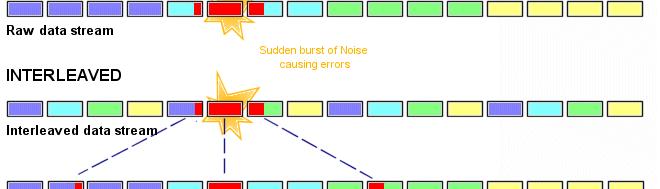
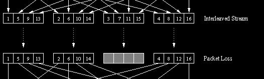
43 //2 Interleaving Generation of interleaving 43
William Stallings Data and Computer Communications. Chapter 7 Data Link Control
 William Stallings Data and Computer Communications Chapter 7 Data Link Control Flow Control Ensuring the sending entity does not overwhelm the receiving entity Preventing buffer overflow Transmission time
Data link layer functions. 2 Computer Networks Data Communications. Framing (1) Framing (2) Parity Checking (1) Error Detection
 Framing (2) Parity Checking (1) Error Detection") 2 Computer Networks Data Communications Part 6 Data Link Control Data link layer functions Framing Needed to synchronise TX and RX Account for all bits sent Error control Detect and correct errors Flow
2 Computer Networks Data Communications Part 6 Data Link Control Data link layer functions Framing Needed to synchronise TX and RX Account for all bits sent Error control Detect and correct errors Flow
Data and Computer Communications
 Data and Computer Communications Chapter 7 Data Link Control Protocols Eighth Edition by William Stallings Lecture slides by Lawrie Brown Data Link Control Protocols "Great and enlightened one," said Ten-teh,
Data Link Control Protocols
 Data Link Control Protocols need layer of logic above Physical to manage exchange of data over a link frame synchronization flow control error control addressing control and data link management Flow Control
 ET3110 Networking and Communications UNIT 2: Communication Techniques and Data Link Control Protocol skong@itt-tech.edutech.edu Learning Objectives Identify methods of detecting errors. Use Hamming code
Chapter 3. The Data Link Layer. Wesam A. Hatamleh
 Chapter 3 The Data Link Layer The Data Link Layer Data Link Layer Design Issues Error Detection and Correction Elementary Data Link Protocols Sliding Window Protocols Example Data Link Protocols The Data
LECTURE #34. Data Communication (CS601)
") LECTURE #34 Error Detection And Correction Methods Longitudinal Red Check(LRC) o In LRC, a block of bits is organized in a table (rows and columns) o For example instead of sending 32 bits, we organize
LECTURE #34 Error Detection And Correction Methods Longitudinal Red Check(LRC) o In LRC, a block of bits is organized in a table (rows and columns) o For example instead of sending 32 bits, we organize
INTERNET ARCHITECTURE & PROTOCOLS
 INTERNET ARCHITECTURE & PROTOCOLS Set # 02 Delivered By: Engr Tahir Niazi Need for Data Link Layer possibility of transmission errors receiver need to regulate the rate at which data arrive that's why
DATA LINK LAYER UNIT 7.
 DATA LINK LAYER UNIT 7 1 Data Link Layer Design Issues: 1. Service provided to network layer. 2. Determining how the bits of the physical layer are grouped into frames (FRAMING). 3. Dealing with transmission
Chapter Six. Errors, Error Detection, and Error Control. Data Communications and Computer Networks: A Business User s Approach Seventh Edition
 Chapter Six Errors, Error Detection, and Error Control Data Communications and Computer Networks: A Business User s Approach Seventh Edition After reading this chapter, you should be able to: Identify
Data Link Control. Surasak Sanguanpong Last updated: 11 July 2000
 1/14 Data Link Control Surasak Sanguanpong nguan@ku.ac.th http://www.cpe.ku.ac.th/~nguan Last updated: 11 July 2000 Flow Control 2/14 technique for controlling the data transmission so that s have sufficient
Ch. 7 Error Detection and Correction
 Ch. 7 Error Detection and Correction Error Detection and Correction Data can be corrupted during transmission. Some applications require that errors be detected and corrected. 2 1. Introduction Let us
Data Link Layer (part 2)
") Data Link Layer (part 2)! Question - What is a major disadvantage of asynchronous transmission? Reference: Chapters 6 and 7 Stallings Study Guide 6! Question - What is a major disadvantage of asynchronous
Data Link Layer (part 2)! Question - What is a major disadvantage of asynchronous transmission? Reference: Chapters 6 and 7 Stallings Study Guide 6! Question - What is a major disadvantage of asynchronous
Lecture 2 Error Detection & Correction. Types of Errors Detection Correction
 Lecture 2 Error Detection & Correction Types of Errors Detection Correction Basic concepts Networks must be able to transfer data from one device to another with complete accuracy. Data can be corrupted
I. INTRODUCTION. each station (i.e., computer, telephone, etc.) directly connected to all other stations
 directly connected to all other stations") I. INTRODUCTION (a) Network Topologies (i) point-to-point communication each station (i.e., computer, telephone, etc.) directly connected to all other stations (ii) switched networks (1) circuit switched
I. INTRODUCTION (a) Network Topologies (i) point-to-point communication each station (i.e., computer, telephone, etc.) directly connected to all other stations (ii) switched networks (1) circuit switched
Data Link Layer. Srinidhi Varadarajan
 Data Link Layer Srinidhi Varadarajan Data Link Layer: Functionality The data link layer must: Detect errors (using redundancy bits) Request retransmission if data is lost (using automatic repeat request
Telecom Systems Chae Y. Lee. Contents. Flow Control Error Detection/Correction Link Control (Error Control) Link Performance (Utility)
 Link Performance (Utility)") Data Link Control Contents Flow Control Error Detection/Correction Link Control (Error Control) Link Performance (Utility) 2 Flow Control Flow control is a technique for assuring that a transmitting entity
Data Link Control Contents Flow Control Error Detection/Correction Link Control (Error Control) Link Performance (Utility) 2 Flow Control Flow control is a technique for assuring that a transmitting entity
SRI RAMAKRISHNA INSTITUTE OF TECHNOLOGY DEPARTMENT OF INFORMATION TECHNOLOGY COMPUTER NETWORKS UNIT - II DATA LINK LAYER
 SRI RAMAKRISHNA INSTITUTE OF TECHNOLOGY DEPARTMENT OF INFORMATION TECHNOLOGY COMPUTER NETWORKS UNIT - II DATA LINK LAYER 1. What are the responsibilities of data link layer? Specific responsibilities of
COMPUTER NETWORKS UNIT-3
 COMPUTER NETWORKS UNIT-3 Syllabus: The Data Link Layer - Data Link Layer Design Issues, Services Provided to the Network Layer Framing Error Control Flow Control, Error Detection and Correction Error-Correcting
PART III. Data Link Layer MGH T MGH C I 204
 PART III Data Link Layer Position of the data-link layer Data link layer duties LLC and MAC sublayers IEEE standards for LANs Chapters Chapter 10 Error Detection and Correction Chapter 11 Data Link Control
Lecture 4: CRC & Reliable Transmission. Lecture 4 Overview. Checksum review. CRC toward a better EDC. Reliable Transmission
 1 Lecture 4: CRC & Reliable Transmission CSE 123: Computer Networks Chris Kanich Quiz 1: Tuesday July 5th Lecture 4: CRC & Reliable Transmission Lecture 4 Overview CRC toward a better EDC Reliable Transmission
This Lecture. BUS Computer Facilities Network Management. Line Discipline. Data Link Layer
 This Lecture US35 - Computer Facilities Network Management Synchronisation and interfacing insufficient by themselves. Need to provide: Flow control - allow the receiver to regulate the flow of data. Error
The data link layer has a number of specific functions it can carry out. These functions include. Figure 2-1. Relationship between packets and frames.
 Module 2 Data Link Layer: - Data link Layer design issues - Error Detection and correction Elementary Data link protocols, Sliding window protocols- Basic Concept, One Bit Sliding window protocol, Concept
EITF25 Internet Techniques and Applications L3: Data Link layer. Stefan Höst
 EITF25 Internet Techniques and Applications L3: Data Link layer Stefan Höst Communication on physical layer To transmit on the physical medium use signals At each computer it can be seen as transmitting
The Data Link Layer Chapter 3
 The Data Link Layer Chapter 3 Data Link Layer Design Issues Error Detection and Correction Elementary Data Link Protocols Sliding Window Protocols Example Data Link Protocols Revised: August 2011 & February
Lecture 6: Reliable Transmission. CSE 123: Computer Networks Alex Snoeren (guest lecture) Alex Sn
 Alex Sn") Lecture 6: Reliable Transmission CSE 123: Computer Networks Alex Snoeren (guest lecture) Alex Sn Lecture 6 Overview Finishing Error Detection Cyclic Remainder Check (CRC) Handling errors Automatic Repeat
Lecture 6: Reliable Transmission CSE 123: Computer Networks Alex Snoeren (guest lecture) Alex Sn Lecture 6 Overview Finishing Error Detection Cyclic Remainder Check (CRC) Handling errors Automatic Repeat
Advanced Computer Networks. Rab Nawaz Jadoon DCS. Assistant Professor COMSATS University, Lahore Pakistan. Department of Computer Science
 Advanced Computer Networks Department of Computer Science DCS COMSATS Institute of Information Technology Rab Nawaz Jadoon Assistant Professor COMSATS University, Lahore Pakistan Advanced Computer Networks
Chapter 7: Data Link Control. CS420/520 Axel Krings Page 1
 Chapter 7: Data Link Control CS420/520 Axel Krings Page 1 Data Link Control Protocols Need layer of logic above Physical to manage exchange of data over a link frame synchronization flow control error
Chapter 7: Data Link Control. Data Link Control Protocols
 Chapter 7: Data Link Control CS420/520 Axel Krings Page 1 Data Link Control Protocols Need layer of logic above Physical to manage exchange of data over a link frame synchronization flow control error
Error Detection Codes. Error Detection. Two Dimensional Parity. Internet Checksum Algorithm. Cyclic Redundancy Check.
 Error Detection Two types Error Detection Codes (e.g. CRC, Parity, Checksums) Error Correction Codes (e.g. Hamming, Reed Solomon) Basic Idea Add redundant information to determine if errors have been introduced
COMPUTER NETWORKS UNIT I. 1. What are the three criteria necessary for an effective and efficient networks?
 Question Bank COMPUTER NETWORKS Short answer type questions. UNIT I 1. What are the three criteria necessary for an effective and efficient networks? The most important criteria are performance, reliability
MYcsvtu Notes DATA REPRESENTATION. Data Types. Complements. Fixed Point Representations. Floating Point Representations. Other Binary Codes
 DATA REPRESENTATION Data Types Complements Fixed Point Representations Floating Point Representations Other Binary Codes Error Detection Codes Hamming Codes 1. DATA REPRESENTATION Information that a Computer
Ad hoc and Sensor Networks Chapter 6: Link layer protocols. Holger Karl
 Ad hoc and Sensor Networks Chapter 6: Link layer protocols Holger Karl Goals of this chapter Link layer tasks in general Framing group bit sequence into packets/frames Important: format, size Error control
Data Link Control Protocols
 Protocols : Introduction to Data Communications Sirindhorn International Institute of Technology Thammasat University Prepared by Steven Gordon on 23 May 2012 Y12S1L07, Steve/Courses/2012/s1/its323/lectures/datalink.tex,
CMSC 2833 Lecture 18. Parity Add a bit to make the number of ones (1s) transmitted odd.
 transmitted odd.") Parity Even parity: Odd parity: Add a bit to make the number of ones (1s) transmitted even. Add a bit to make the number of ones (1s) transmitted odd. Example and ASCII A is coded 100 0001 Parity ASCII
Parity Even parity: Odd parity: Add a bit to make the number of ones (1s) transmitted even. Add a bit to make the number of ones (1s) transmitted odd. Example and ASCII A is coded 100 0001 Parity ASCII
(Refer Slide Time: 2:20)
") Data Communications Prof. A. Pal Department of Computer Science & Engineering Indian Institute of Technology, Kharagpur Lecture-15 Error Detection and Correction Hello viewers welcome to today s lecture
Data Communications Prof. A. Pal Department of Computer Science & Engineering Indian Institute of Technology, Kharagpur Lecture-15 Error Detection and Correction Hello viewers welcome to today s lecture
Link Layer: Error detection and correction
 Link Layer: Error detection and correction Topic Some bits will be received in error due to noise. What can we do? Detect errors with codes Correct errors with codes Retransmit lost frames Later Reliability
Chapter 10 Error Detection and Correction. Copyright The McGraw-Hill Companies, Inc. Permission required for reproduction or display.
 Chapter 10 Error Detection and Correction 0. Copyright The McGraw-Hill Companies, Inc. Permission required for reproduction or display. Note The Hamming distance between two words is the number of differences
CS321: Computer Networks Error Detection and Correction
 CS321: Computer Networks Error Detection and Correction Dr. Manas Khatua Assistant Professor Dept. of CSE IIT Jodhpur E-mail: manaskhatua@iitj.ac.in Error Detection and Correction Objective: System must
Achieving Reliable Digital Data Communication through Mathematical Algebraic Coding Techniques
 International Journal of Pure and Applied Mathematical Sciences. ISSN 0972-9828 Volume 9, Number 2 (2016), pp. 183-190 Research India Publications http://www.ripublication.com Achieving Reliable Digital
ERROR AND FLOW CONTROL. Lecture: 10 Instructor Mazhar Hussain
 ERROR AND FLOW CONTROL Lecture: 10 Instructor Mazhar Hussain 1 FLOW CONTROL Flow control coordinates the amount of data that can be sent before receiving acknowledgement It is one of the most important
CS 640 Introduction to Computer Networks. Role of data link layer. Today s lecture. Lecture16
 Introduction to Computer Networks Lecture16 Role of data link layer Service offered by layer 1: a stream of bits Service to layer 3: sending & receiving frames To achieve this layer 2 does Framing Error
The Data Link Layer Chapter 3
 The Data Link Layer Chapter 3 Data Link Layer Design Issues Error Detection and Correction Elementary Data Link Protocols Sliding Window Protocols Example Data Link Protocols Revised: August 2011 The Data
Flow control: Ensuring the source sending frames does not overflow the receiver
 Layer 2 Technologies Layer 2: final level of encapsulation of data before transmission over a physical link responsible for reliable transfer of frames between hosts, hop by hop, i.e. on a per link basis
CSN Telecommunications. 5: Error Coding. Data, Audio, Video and Images Prof Bill Buchanan
 CSN874 Telecommunications 5: Error Coding Data, Audio, Video and Images http://asecuritysite.com/comms Prof Bill Buchanan CSN874 Telecommunications 5: Error Coding: Modulo-2 Data, Audio, Video and Images
Chapter 3. The Data Link Layer
 Chapter 3 The Data Link Layer 1 Data Link Layer Algorithms for achieving reliable, efficient communication between two adjacent machines. Adjacent means two machines are physically connected by a communication
CSMC 417. Computer Networks Prof. Ashok K Agrawala Ashok Agrawala. Nov 1,
 CSMC 417 Computer Networks Prof. Ashok K Agrawala 2018 Ashok Agrawala 1 Message, Segment, Packet, and Frame host host HTTP HTTP message HTTP TCP TCP segment TCP router router IP IP packet IP IP packet
CSE 461: Framing, Error Detection and Correction
 CSE 461: Framing, Error Detection and Correction Next Topics Framing Focus: How does a receiver know where a message begins/ends Error detection and correction Focus: How do we detect and correct messages
The flow of data must not be allowed to overwhelm the receiver
 Data Link Layer: Flow Control and Error Control Lecture8 Flow Control Flow and Error Control Flow control refers to a set of procedures used to restrict the amount of data that the sender can send before
Point-to-Point Links. Outline Encoding Framing Error Detection Sliding Window Algorithm. Fall 2004 CS 691 1
 Point-to-Point Links Outline Encoding Framing Error Detection Sliding Window Algorithm Fall 2004 CS 691 1 Encoding Signals propagate over a physical medium modulate electromagnetic waves e.g., vary voltage
Transmission SIGNALs
 Chapter 6 Digital Communications Basics 6.1 Introduction 6.2 Transmission media 6.3 Source of signal impairment 6.4 Asynchronous Transmission 6.5 Synchronous Transmission 6.6 Error Detection Methods 6.7
TYPES OF ERRORS. Data can be corrupted during transmission. Some applications require that errors be detected and corrected.
 Data can be corrupted during transmission. Some applications require that errors be detected and corrected. TYPES OF ERRORS There are two types of errors, 1. Single Bit Error The term single-bit error
Department of Computer and IT Engineering University of Kurdistan. Data Communication Netwotks (Graduate level) Data Link Layer
 Data Link Layer") Department of Computer and IT Engineering University of Kurdistan Data Communication Netwotks (Graduate level) Data Link Layer By: Dr. Alireza Abdollahpouri Data Link Layer 2 Data Link Layer Application
Department of Computer and IT Engineering University of Kurdistan Data Communication Netwotks (Graduate level) Data Link Layer By: Dr. Alireza Abdollahpouri Data Link Layer 2 Data Link Layer Application
2.4 Error Detection Bit errors in a frame will occur. How do we detect (and then. (or both) frames contains an error. This is inefficient (and not
 frames contains an error. This is inefficient (and not") CS475 Networks Lecture 5 Chapter 2: Direct Link Networks Assignments Reading for Lecture 6: Sections 2.6 2.8 Homework 2: 2.1, 2.4, 2.6, 2.14, 2.18, 2.31, 2.35. Due Thursday, Sept. 15 2.4 Error Detection
CS475 Networks Lecture 5 Chapter 2: Direct Link Networks Assignments Reading for Lecture 6: Sections 2.6 2.8 Homework 2: 2.1, 2.4, 2.6, 2.14, 2.18, 2.31, 2.35. Due Thursday, Sept. 15 2.4 Error Detection
2.1 CHANNEL ALLOCATION 2.2 MULTIPLE ACCESS PROTOCOLS Collision Free Protocols 2.3 FDDI 2.4 DATA LINK LAYER DESIGN ISSUES 2.5 FRAMING & STUFFING
 UNIT-2 2.1 CHANNEL ALLOCATION 2.2 MULTIPLE ACCESS PROTOCOLS 2.2.1 Pure ALOHA 2.2.2 Slotted ALOHA 2.2.3 Carrier Sense Multiple Access 2.2.4 CSMA with Collision Detection 2.2.5 Collision Free Protocols 2.2.5.1
T325 Summary T305 T325 B BLOCK 4 T325. Session 3. Dr. Saatchi, Seyed Mohsen. Prepared by:
 T305 T325 B BLOCK 4 T325 Summary Prepared by: Session 3 [Type Dr. Saatchi, your address] Seyed Mohsen [Type your phone number] [Type your e-mail address] Dr. Saatchi, Seyed Mohsen T325 Error Control Coding
Chapter 6 Digital Data Communications Techniques
 Chapter 6 Digital Data Communications Techniques Asynchronous and Synchronous Transmission timing problems require a mechanism to synchronize the transmitter and receiver receiver samples stream at bit
3. Data Link Layer 3-2
 3. Data Link Layer 3.1 Transmission Errors 3.2 Error Detecting and Error Correcting Codes 3.3 Bit Stuffing 3.4 Acknowledgments and Sequence Numbers 3.5 Flow Control 3.6 Examples: HDLC, PPP 3. Data Link
FAULT TOLERANT SYSTEMS
 FAULT TOLERANT SYSTEMS http://www.ecs.umass.edu/ece/koren/faulttolerantsystems Part 6 Coding I Chapter 3 Information Redundancy Part.6.1 Information Redundancy - Coding A data word with d bits is encoded
Chapter 10 Error Detection and Correction 10.1
 Chapter 10 Error Detection and Correction 10.1 10-1 INTRODUCTION some issues related, directly or indirectly, to error detection and correction. Topics discussed in this section: Types of Errors Redundancy
CSEP 561 Error detection & correction. David Wetherall
 CSEP 561 Error detection & correction David Wetherall djw@cs.washington.edu Codes for Error Detection/Correction ti ti Error detection and correction How do we detect and correct messages that are garbled
Wireless Sensornetworks Concepts, Protocols and Applications. Chapter 5b. Link Layer Control
 Wireless Sensornetworks Concepts, Protocols and Applications 5b Link Layer Control 1 Goals of this cha Understand the issues involved in turning the radio communication between two neighboring nodes into
ELG3175 Introduction to Communication Systems. Introduction to Error Control Coding
 ELG375 Introduction to Communication Systems Introduction to Error Control Coding Types of Error Control Codes Block Codes Linear Hamming, LDPC Non-Linear Cyclic BCH, RS Convolutional Codes Turbo Codes
CSE123A discussion session
 CSE23A discussion session 27/2/9 Ryo Sugihara Review Data Link Layer (3): Error detection sublayer CRC Polynomial representation Implementation using LFSR Data Link Layer (4): Error recovery sublayer Protocol
CSCI-1680 Link Layer Reliability Rodrigo Fonseca
 CSCI-1680 Link Layer Reliability Rodrigo Fonseca Based partly on lecture notes by David Mazières, Phil Levis, John Janno< Last time Physical layer: encoding, modulation Link layer framing Today Getting
EE 122: Error detection and reliable transmission. Ion Stoica September 16, 2002
 EE 22: Error detection and reliable transmission Ion Stoica September 6, 2002 High Level View Goal: transmit correct information Problem: bits can get corrupted - Electrical interference, thermal noise
Inst: Chris Davison
 ICS 153 Introduction to Computer Networks Inst: Chris Davison cbdaviso@uci.edu ICS 153 Data Link Layer Contents Simplex and Duplex Communication Frame Creation Flow Control Error Control Performance of
CS254 Network Technologies. Lecture 2: Network Models & Error Detection and Correction. Dr Nikos Antonopoulos
 CS254 Network Technologies Lecture 2: Network Models & Error Detection and Correction Dr Nikos Antonopoulos Department of Computing University of Surrey Autumn 2006 2.1 Layered Tasks Sender, Receiver,
Lecture 5. Homework 2 posted, due September 15. Reminder: Homework 1 due today. Questions? Thursday, September 8 CS 475 Networks - Lecture 5 1
 Lecture 5 Homework 2 posted, due September 15. Reminder: Homework 1 due today. Questions? Thursday, September 8 CS 475 Networks - Lecture 5 1 Outline Chapter 2 - Getting Connected 2.1 Perspectives on Connecting
ELEC 691X/498X Broadcast Signal Transmission Winter 2018
 ELEC 691X/498X Broadcast Signal Transmission Winter 2018 Instructor: DR. Reza Soleymani, Office: EV 5.125, Telephone: 848 2424 ext.: 4103. Office Hours: Wednesday, Thursday, 14:00 15:00 Slide 1 In this
Data Link Control Layer, Error Detection, Error Correction, and Framing
 Data Link Control Layer, Error Detection, Error Correction, and Framing EEE 538, WEEK 2 Dr. Nail Akar Bilkent University Electrical and Electronics Engineering Department 1 Error Detection Techniques Used
CSCI-1680 Link Layer Reliability John Jannotti
 CSCI-1680 Link Layer Reliability John Jannotti Based partly on lecture notes by David Mazières, Phil Levis, Rodrigo Fonseca Roadmap Last time Physical layer: encoding, modulation Link layer framing Today
CSE 123: Computer Networks
 Student Name: PID: UCSD email: CSE 123: Computer Networks Homework 1 Solution (Due 10/12 in class) Total Points: 30 Instructions: Turn in a physical copy at the beginning of the class on 10/10. Problems:
High Level View. EE 122: Error detection and reliable transmission. Overview. Error Detection
 High Level View EE 22: Error detection and reliable transmission Ion Stoica September 6, 22 Goal: transmit correct information Problem: bits can get corrupted - Electrical interference, thermal noise Solution
CSMC 417. Computer Networks Prof. Ashok K Agrawala Ashok Agrawala Set 4. September 09 CMSC417 Set 4 1
 CSMC 417 Computer Networks Prof. Ashok K Agrawala 2009 Ashok Agrawala Set 4 1 The Data Link Layer 2 Data Link Layer Design Issues Services Provided to the Network Layer Framing Error Control Flow Control
Data Link Layer. Goals of This Lecture. Engineering Questions. Outline of the Class
 Data Link Layer Kuang Chiu Huang TCM NCKU Goals of This Lecture Through the lecture and in-class discussion, students are enabled to describe role and functions of the link layer, and compare different
Outline. EEC-484/584 Computer Networks. Data Link Layer Design Issues. Framing. Lecture 6. Wenbing Zhao Review.
 EEC-484/584 Computer Networks Lecture 6 wenbing@ieee.org (Lecture nodes are based on materials supplied by Dr. Louise Moser at UCSB and Prentice-Hall) Outline Review Data Link Layer Design Issues Error
Data Link Layer. Overview. Links. Shivkumar Kalyanaraman
 Data Link Layer shivkuma@ecse.rpi.edu http://www.ecse.rpi.edu/homepages/shivkuma 1-1 Based in part upon the slides of Prof. Raj Jain (OSU) Overview The data link layer problem Error detection and correction
Networked Systems and Services, Fall 2018 Chapter 2. Jussi Kangasharju Markku Kojo Lea Kutvonen
 Networked Systems and Services, Fall 2018 Chapter 2 Jussi Kangasharju Markku Kojo Lea Kutvonen Outline Physical layer reliability Low level reliability Parities and checksums Cyclic Redundancy Check (CRC)
UNIT-II 1. Discuss the issues in the data link layer. Answer:
 UNIT-II 1. Discuss the issues in the data link layer. Answer: Data Link Layer Design Issues: The data link layer has a number of specific functions it can carry out. These functions include 1. Providing
Communication Fundamentals in Computer Networks
 Lecture 7 Communication Fundamentals in Computer Networks M. Adnan Quaium Assistant Professor Department of Electrical and Electronic Engineering Ahsanullah University of Science and Technology Room 4A07
INF Data Communication Data Link Layer
 INF3190 - Data Communication Data Link Layer Carsten Griwodz Email: griff@ifi.uio.no most slides from: Ralf Steinmetz, TU Darmstadt and a few from Olav Lysne, J. K. Kurose og K. W. Ross Function, Services
Data Link Layer: Overview, operations
 Data Link Layer: Overview, operations Chapter 3 1 Outlines 1. Data Link Layer Functions. Data Link Services 3. Framing 4. Error Detection/Correction. Flow Control 6. Medium Access 1 1. Data Link Layer
Fault Tolerance & Reliability CDA Chapter 2 Additional Interesting Codes
 Fault Tolerance & Reliability CDA 5140 Chapter 2 Additional Interesting Codes m-out-of-n codes - each binary code word has m ones in a length n non-systematic codeword - used for unidirectional errors
CSCI-1680 Link Layer I Rodrigo Fonseca
 CSCI-1680 Link Layer I Rodrigo Fonseca Based partly on lecture notes by David Mazières, Phil Levis, John Jannotti Last time Physical layer: encoding, modulation Today Link layer framing Getting frames
CS422 Computer Networks
 CS422 Computer Networks Lecture 3 Data Link Layer Dr. Xiaobo Zhou Department of Computer Science CS422 DataLinkLayer.1 Data Link Layer Design Issues Services Provided to the Network Layer Provide service
CHANNEL CODING 1. Introduction
 CHANNEL CODING 1. Introduction The fundamental resources at the disposal of a communications engineer are signal power, time and bandwidth. For a given communications environment, these three resources
The Data Link Layer. Data Link Layer Design Issues
 The Data Link Layer Chapter 3 Data Link Layer Design Issues Network layer services Framing Error control Flow control 1 Packets and Frames Relationship between packets and frames. Network Layer Services
Data Link Technology. Suguru Yamaguchi Nara Institute of Science and Technology Department of Information Science
 Data Link Technology Suguru Yamaguchi Nara Institute of Science and Technology Department of Information Science Agenda Functions of the data link layer Technologies concept and design error control flow
CSE123A discussion session
 CSE123A discussion session 2007/02/02 Ryo Sugihara Review Data Link layer (1): Overview Sublayers End-to-end argument Framing sublayer How to delimit frame» Flags and bit stuffing Topics Data Link Layer
Chapter 3 The Data Link Layer
 Chapter 3 The Data Link Layer 陳瑞奇 (Rikki) 亞洲大學資訊工程學系 Adapted from Computer Networks, Andrew S. Tanenbaum, Vrije University, Netherlands & Computer Networking: A Top Down Approach, Jim Kurose, Keith Ross
Survey on Error Control Coding Techniques
 Survey on Error Control Codin Techniques Suriya.N 1 SNS Collee of Enineerin, Department of ECE, surikala@mail.com S.Kamalakannan 2 SNS Collee of Enineerin, Department of ECE, kamalakannan.ap@mail.com Abstract
CSE 123: Computer Networks Alex C. Snoeren. HW 1 due Thursday!
 CSE 123: Computer Networks Alex C. Snoeren HW 1 due Thursday! Error handling through redundancy Adding extra bits to the frame Hamming Distance When we can detect When we can correct Checksum Cyclic Remainder
Errors. Chapter Extension of System Model
 Chapter 4 Errors In Chapter 2 we saw examples of how symbols could be represented by arrays of bits. In Chapter 3 we looked at some techniques of compressing the bit representations of such symbols, or
Framing, Synchronization, and Error Detection
 Exercise 4 Framing, Synchronization, and Error Detection EXERCISE OBJECTIVE When you have completed this exercise, you will be familiar with the ADSL superframe structure. You will be able to demonstrate
Direct Link Communication I: Basic Techniques. Data Transmission. ignore carrier frequency, coding etc.
 Direct Link Communication I: Basic Techniques Link speed unit: bps abstraction Data Transmission ignore carrier frequency, coding etc. Point-to-point link: wired or wireless includes broadcast case Interested
EITF25 Internet- - Techniques and Applica8ons Stefan Höst. L4 Data link (part 1)
") EITF25 Internet- - Techniques and Applica8ons Stefan Höst L4 Data link (part 1) Previously on EITF25 (or digital signal) 2 Data Link Layer Medium Access Control Access to network Logical Link Control Node-
EITF25 Internet- - Techniques and Applica8ons Stefan Höst L4 Data link (part 1) Previously on EITF25 (or digital signal) 2 Data Link Layer Medium Access Control Access to network Logical Link Control Node-
Telecommunication Protocols Laboratory Course
 Telecommunication Protocols Laboratory Course G721 Lecture 1 Behind the name Telecommunication: the science and technology of transmitting information (words, sounds, images) over great distances, in the
Overview. Data Link Technology. Role of the data-link layer. Role of the data-link layer. Function of the physical layer
 Overview Data Link Technology Functions of the data link layer Technologies concept and design error control flow control fundamental protocols Suguru Yamaguchi Nara Institute of Science and Technology
Networking Link Layer
 Networking Link Layer ECE 650 Systems Programming & Engineering Duke University, Spring 2018 (Link Layer Protocol material based on CS 356 slides) TCP/IP Model 2 Layer 1 & 2 Layer 1: Physical Layer Encoding