Record Specification and File Format for Specifying a Power Flow Case
|
|
|
- Damian Welch
- 5 years ago
- Views:
Transcription

 384-6330 ext.")
1 Record Specification and File Format for Specifying a Power Flow Case Prepared for : PowerWorld Users Date : 2018 Prepared by : James Weber, Ph.D. Director of Software Development PowerWorld Corporation (217) ext. 13 weber@powerworld.com 2001 South First Street Champaign, IL (217)
2 Table of Contents 1 DOCUMENT SUMMARY BASIC FILE FORMAT RULES SYNTAX RULES Naming Conventions Handling quotes inside of quoted strings OBJECT TYPE STRINGS Branch Objects (2-terminal AC devices) SPECIFYING AN OBJECT USING A STRING Primary Keys Secondary Keys Label Identifiers AllLabels Field Naming Collisions SPECIAL TREATMENT OF BUSNUM INTEGER KEY FIELDS AGGREGATION OBJECT NOTES AREA, BALANCINGAUTHORITY, AND ZONE OBJECTS Defining Area, BalancingAuthority, Zone objects Using Area, BalancingAuthority, and Zone objects in Filtering Using Area, BalancingAuthority, and Zone objects with regard to losses on Tie-lines SUBSTATIONS OWNER DATAMAINTAINER Specification of DataMaintainer within Software Objects that don t support DataMaintainer (NO/NO) Objects to which DataMaintainer can be assigned, but Inheritance is not allowed Objects that Can Inherit a DataMaintainer DataMaintainer being assigned its own DataMaintainer OBJECT DEFINITIONS PWCASEINFORMATION DATAMAINTAINER OWNER LOADMODELGROUP SUBSTATION XFCORRECTION VOLTAGECONTROLGROUP LIMIT_MONITORING_OPTIONS_VALUE LIMITSET i
3 4.9.1 Branch and Interface relationship to LimitSet Bus relationship to LimitSet RATINGSETNAMEBRANCH RATINGSETNAMEINTERFACE RATINGSETNAMEBUS BUS GEN REACTIVECAPABILITY LOAD BRANCH (NOT A TRANSFORMER) BRANCH (TRANSFORMER) WXFORMER MULTISECTIONLINE SHUNT (SHUNTMODE = BUS SHUNT) SHUNT (SHUNTMODE <> BUS SHUNT) LINESHUNT DFACTSCORRECTION DFACTS DCTRANSMISSIONLINE VSCDCLINE MTDCRECORD, MTDCBUS, MTDCCONVERTER, MTDCTRANSMISSIONLINE INJECTIONGROUP, PARTPOINT SUPERAREA AREA STUDYMWTRANSACTION BALANCINGAUTHORITY ZONE INTERFACE, INTERFACEELEMENT SIM_SOLUTION_OPTIONS_VALUE NOMOGRAM USING POWERWORLD SIMULATOR TO SAVE THIS INFORMATION FILE, SAVE AS METHOD CREATE AN AUXILIARY FILE EXPORT FORMAT DESCRIPTION ii
4 1 Document Summary This document will describe a database structure which can be used to store all information which is needed to replicate a power flow case in either a RAW, EPC or PowerWorld AUX file. This syntax is the same syntax used for the WECC Common Format for Contingency and RAS Definitions and would provide a template for sharing data among engineers in an open format managed by PowerWorld Corporation. 2 Basic File Format Rules 2.1 Syntax Rules The following is a list of general syntax rules that apply throughout this file format: All strings are case insensitive. Thus "Contingency" is treated the same as "CONTINGENCY" or "contingency" or "CoNtInGeNcY". This will be true for names, fields, and any key words in the file syntax. Any line that starts with the two backslashes (//) will be treated as a comment and be ignored when parsing the file. Text appearing after two backslashes will also be treated as comments. Blank lines of text are ignored and skipped Many text lines are space delimited strings that use double quotes ("") as string unifiers. Note that these are straight quotes. Smart quotes such as are not supported by the format so be careful when copying and pasting from some text editors. Any TAB characters in the text file will be treated as a single space when read by a file parser Consecutive spaces in the position of a delimiter are treated as a one string delimiter Naming Conventions There are many objects in this file format that have a name including Model Conditions, Model Filters, Model Expressions, Contingencies, Remedial Action Schemes, and Injection Groups. There will be no restrictions placed on the length or content of the names in this format, except that they are limited to ASCII characters. Obviously the user should use discretion and not create names with 1,500 characters, but the file format will not specifically preclude this bad behavior Handling quotes inside of quoted strings There are many places in the file format that require a string enclosed in either double quotes or single quotes. Sometimes there are even double quote strings that contain a space delimited string that uses single quotes inside of the double quotes. For example, to specify a particular area, a space delimited string containing the string AREA followed by the name of the area enclosed in single quotes is used. The entire string is then enclosed in double quotes. However, if the name of the area contains either double or single quotes, this could cause 3
5 trouble in the text parser. To accommodate this potential, the format specifies that such quotes or double quotes be repeated if contained inside of a string. Consider the examples in the following table: Area Name WECC's Office Object ID String "AREA 'WECC''s Office'" "HIGH" Point s "AREA '""HIGH"" Point''s'" In most situations such as object names, using quotes or double quotes is highly discouraged. However, it may be natural to include quotes in some of the fields in this document such as the Memo field for a contingency. The memo field is a free-form string in which the user includes notes about the contingency. Thus in general, this format will not enforce any requirement regarding quotes because in the end it is not necessary. The format will require that software parsers handle these situations. 2.2 Object Type Strings There are many places in this file format where a particular object type must be referenced. All object type strings must not contain any spaces. The following is a list of some of the allowable object types: Branch, Bus, Gen, Shunt, Load, Area, Zone, Substation, InjectionGroup, Interface, 3WXFormer, DCTransmissionLine, LineShunt, VSCDCLine, ModelExpression, Contingency, ContingencyElement, TSContingency, TSContingencyElement, RemedialAction, RemedialActionElement, CTG_Options_Value, Sim_Solution_Options_Value, LimitSet, CustomMonitor, ModelFilter, ModelFilterCondition, ModelCondition, ModelConditionCondition, Filter, Condition Branch Objects (2-terminal AC devices) An object type BRANCH signifies either an AC transmission line, 2-winding transformer, a series capacitor or reactor, or any AC device which connects two buses. Within a BRANCH there is then a field BranchDeviceType which can have the following entries: Line, Transformer, Series Cap, Breaker, Disconnect, ZBR, Fuse, Load Break Disconnect, or Ground Disconnect. This enumeration of device types comes from the Common Information Model (CIM) specification, except that a ZBR is called a Jumper in CIM. In general a user may toggle between these various device types, with the exception of a Transformer. Once an object is specified as a transformer it may not be turned back into a another branch device type. 2.3 Specifying an object using a string There are many places in this file format where a particular object must be referenced. In these situations a string will be specified that is enclosed in double quotes. The object string will be space delimited with the first string representing the object type. Object type strings from Section 2.2 will never have spaces in them. Following the object type string there will be identification information for the object. This information allows for three potential formats that the software will need to parse: Primary Keys, Secondary Keys, or Labels. While each object can have labels, each different object type can have a different number of key fields. The key fields for the various object types are as follows: 4
6 Object Type Primary Key Fields Secondary Key Fields Gen BusNum ID Bus Number NameNomkV Branch BusNumFrom BusNumTo Circuit Circuit BusNameNomkV ID BusNameNomkVFrom BusNameNomkVTo Load BusNum ID BusNameNomkV ID Shunt BusNum ID BusNameNomkV ID Area Number Name Zone Number Name Substation Number Name InjectionGroup Name none available Interface Name Number 3WXformer BusNumPri BusNumSec BusNumTer Circuit DCTransmissionLine BusNumRect BusNumInv Circuit LineShunt BusNumFrom BusNumTo BusNumLoc Circuit ID BusNameNomkVPri BusNameNomkVSec BusNameNomkVTer Circuit BusNameNomkVRect BusNameNomkVInv Circuit BusNameNomkVFrom BusNameNomkVTo BusNameNomkVLoc Circuit ID VSCDCLine Name none available ModelExpression Name none available Primary Keys Primary keys for many objects are the bus numbers associated with the object and some string identifiers. The format of the object string using primary keys is then the object type and then a list of keys separated by spaces. If a key string has any spaces, a single quote must be used to enclose the key. Note: A single quote is used because throughout the format these entire object strings are enclosed in double quotes. General Format Generator "Objecttype 'key1' 'key2' 'key3'" "GEN 23 '12'" Bus "BUS 33" "BRANCH 'AB'" Branch 3WXformer Area "AREA 51" Zone "ZONE 93" Substation "SUBSTATION 37" "3WXFORMER 'AB'" Secondary Keys Secondary keys for some objects are also available. These are often a combination of the bus name and nominal kv value of a bus, or for other objects they replace the numbers with names. Not all objects will have secondary key fields. For example, an injection group has only a name. 5
7 "Objecttype 'key1' 'key2' 'key3'" General Format Generator "GEN 'Bus 23_138.00' '12'" Bus "BUS 'Bus 33_500.00'" Branch "BRANCH 'Bus 23_138.00' 'Bus 29_138.00' 'AB'" Area "AREA 'Fifty One'" Zone "ZONE 'Ninety Three'" Substation "SUBSTATION 'Thirty Seven'" One special note regarding commonly used secondary keys that use the Name_NomkV convention. When reading this string from input, the string is processed by starting at the last character and searching backward until an underscore (_) character is found. The string is then split between the name and the Nominal voltage. When comparing whether two voltage are equal for the purposes of the nominal voltage we check to see if the string s value (call this StringNomkV) is within 0.1% of an existing bus nominal kv (call this BusNomkV). Said mathematically, perform the following check abs(busnomkv - StringNomkV)/ BusNomkV < 0.001) This ensures that nominal voltages are equal to at least 3 significant digits Label Identifiers Label Identifiers are can also be specified for a particular object. Each particular object could potentially have multiple labels assigned to them, but within one object type, only one object can have a particular label. The format of the object string using a label is then simply the object type followed by the label enclosed in single quotes. General Format Generator Bus Branch "Objecttype 'label'" "GEN 'GrandCoule12'" "BUS 'Coulee_N56'" "BRANCH 'CaptJackGrizzly_56" AllLabels Field Many objects related to the topology of the model have a field associated with them called AllLabels. Objects can have more than one label associated with them but within one object type, only one object can have a particular label. The AllLabels field is a single comma-delimited string containing all the labels assigned to one particular object. Also remember that in the format each AllLabels field is enclosed in double quotes. To accommodate these conventions, if any label contains a comma, then this string for the label will use a single quote as the unifying character around a single label. In addition, for all labels any single quotes or double quotes must be repeated. Consider the examples in the following table showing how AllLabels field is constructed for 3 labels. Label #1 Label #2 Label #3 AllLabels Field writing to format DEF Bob"s,Home Requires unifying single quotes, repeated double quote ABC 'Care' Requires repeated single quotes West East North "West,East,North" 6 "DEF,'Bob""s,Home',ABC ''Care''" Repeated quotes are highlighted in yellow Unifying single quotes highlighted in green
8 Using quotes, double quotes, or commas in a label is discouraged, but the format does not prevent this. Thus in general, this format will not enforce any requirement regarding quotes because in the end it is not necessary. The format will require that software parsers handle these situations Naming Collisions It is possible in this format for a power system model to have secondary fields which do not create a unique identifier for the case. For example, the secondary key fields for buses are the concatenation of the Name and Nominal kv. These are almost always unique, but not always. For example, a recent WECC cases and there are 4 buses named CanyonGT at 13.8 kv (numbers ). When reading from a file referencing the bus "CanyonGT_13.8", this format would just pick the one that a software vendors search routine finds first. There is no guarantee that this will be the one intended, so this is something the user must be careful with if using secondary key fields. It is also possible for the label identifiers to collide with the secondary keys as well. Our experience in practice is that the labels are derived from unique identifiers in the EMS models which are longer than the secondary key strings and are a concatenation of the substation name(s), some unique delimiter like a $. Thus in practice this shouldn t happen, but it is possible. It is even possible with labels that there could be a conflict between the primary key and the label. We do not expect to see too many buses with a label of 1234, but a user could do something like that. Regardless of these hypothetical limitations, when parsing these strings, this format instructs that software parsers will always look first for the primary keys, then the secondary keys, and finally for any of the labels. Thus if there is a conflict between secondary keys and the labels, then the secondary key will have precedence. 2.4 Special Treatment of BusNum Integer Key Fields Many objects use the bus number as one primary key field. This discussion does not apply to the Bus objecttype itself, but instead includes Gen, Load, Shunt, LineShunt, Branch, DCTransmissionLine, MTDCConverter, DFACTS, 3WXformer, and GenVarLim objects. Following the strict definition of the BusNum as an integer key field would require you to use this integer whenever you create one of these object types. However, the format makes special provisions to allow the use of the terminal bus Name_NomkV (secondary key for bus) or one of the bus labels instead. In order to do this, when reading a record which uses the BusNum as a key, the software should interpret this as follows. 1. If the string read to is an integer, then attempt to lookup the bus using this integer otherwise the bus is not found. 2. If no bus was found in step 1, then attempt to split the string in the format of Name followed by an underscore and then followed by the nominal voltage. Then search for a bus which has this name and nominal voltage as described in Section If still no bus is found then attempt to search for a bus with a label that matches the string. In this way, new objects can be optionally created without referring to integer identifiers but instead referring to either secondary or label identifiers of the bus. 7
9 3 Aggregation Object Notes There are several aggregation definitions which can group together objects in a particular manner. The treatment in the data structure for these is defined here. 3.1 Area, BalancingAuthority, and Zone objects Area, BalancingAuthority and Zone objects have the same treatment in the data structure. We will first introduce how to define (input) the area and zone definitions and then discuss how the areas and zones are used. How the Area and Zone definitions are interpreted will depend on where they are used Defining Area, BalancingAuthority, Zone objects Each Bus in the model must be assigned to exactly one Area, exactly one BalancingAuthority and exactly one Zone. Note that there does not need to be any relationship at all between Area, BalancingAuthority and Zone objects. Frequently a zone is modeled as a sub-region of an area, but this does not need to be true. In most situations this is the end of the input specification, however, the objects Gen, Load, and Shunt may also be assigned to an Area, BalancingAuthority or Zone that is different than the terminal bus Using Area, BalancingAuthority, and Zone objects in Filtering How the Area and Zone definitions are interpreted will depend on where they are used. For example, when filtering devices Gen, Load, or Shunt objects then they will obey any area/ba/zone assigned to the particular object, or if none is assigned they will use the area/ba/zone designation with the terminal bus. For devices that have multiple terminals though, such as a Branch or DCTranmissionLine, then the device will be considered inside the area, BA, or zone if any of its terminals is inside. Interfaces will be inside an area, BA, or zone if any of the InterfaceElement devices are inside it Using Area, BalancingAuthority, and Zone objects with regard to losses on Tie-lines When looking at which Area, BalancingAuthority, or Zone object is assigned the losses on a tie-line between two of them, then the device connecting them will have a MeteredEnd specified. The losses will then be assigned to the non-metered end. 3.2 Substations Each Bus in the model can be assigned to one substation. This is not a requirement, but an option. For the purposes of filtering, an object is considered to meet the substation filter if any of the terminal buses are in the substation. 3.3 Owner Owners are a slight modification to the aggregation concept because for some devices (Gen, Branch, Shunt), the object can be partially owned by several different Owner objects. When used with filtering the device will be considered inside the Owner if any part of it is owned. When showing totals such as total generation MW or Mvar, then a pro-rated portion of the generation output will be shown. 8
10 3.4 DataMaintainer DataMaintainer objects represent entities responsible for maintaining the input data for objects in the model. The DataMaintainer object serves 2 purposes 1. If you suspect a piece of data in a case is in error you now have contact information in the form of an or phone number of someone to contact to ask about this data 2. Software has features that allow a user to write out only the data that belongs to a particular DataMaintainer. This construct makes it easier to divide a case into chunks that represent the responsibility of maintaining particular data. The following statements describe how DataMaintainers relate to other objects. 1. Some objects can be assigned a specified DataMaintainer. 2. Some objects may inherit their DataMaintainer from a related object. 3. Not all object types can even be considered to belong to a DataMaintainer. 4. Ultimately, an object can belong to only one DataMaintainer, and the assumption is that all fields associated with that object are the responsibility of the DataMaintainer. 5. Caveat to statement 4: a DataMaintainer object itself can belong to another DataMaintainer. In this way groups of DataMaintainers can be created. Each ObjectType has 2 YES and NO questions based on the first two statements above. Can it be assigned a DataMaintainer? YES or No. Can it Inherit its DataMaintainer from a related object? YES or NO. This gives us 4 permutations to the Assign/Inherit questions: YES/YES, YES/NO, NO/YES and NO/NO Specification of DataMaintainer within Software Within PowerWorld objects there are potentially 2 different columns associated with a DataMaintainer. DataMaintainerAssign column is the column that should be used to directly assign a DataMaintainer to a specific object. If an object does not have a DataMaintainer specified directly then this field is just blank. In addition, to clear the DataMaintainerAssign specification you can set this column to a blank string as well. Only objects that support having a DataMaintainer assigned will have this field. DataMaintainer column is the column that will show the active DataMaintainer for the object. This will show the inherited DataMaintainer if one is available. An object that either can have the DataMaintainer assigned or can inherited the DataMaintainer will include this field. [DataMaintainerInherit were added in Version 19, build on December 1, 2016] DataMaintainerInherit column is a YES/NO field. A value of YES indicates that inheritance is allowed for this objects o For objects listed below which do not allow Inheritance, this field is not enterable and will always show NO. o For objects below which AlwaysInherit, this field will also not be enterable and will always show YES. o For the small list of objects such as Bus, Gen, Load, Shunt, LineShunt, Branch, 3WXFormer, DFACTS, DCTransmissionLine, MTDCRecord and VSCDCLine which can have their own DataMaintainer assigned, but also can inherit the DataMaintainer, then this field will be enterable and the user may toggle the value between YES or NO. Setting the 9
11 value to NO will prevent these objects from inheriting a DataMaintainer. See the purple dots in Section below for an indication of objects which can toggle this field. [DataMaintainerInheritBlock were added in Version 19, build on December 1, 2016] DataMaintainerInheritBlock column is a YES/NO field only available for a Bus and a Substation record. See the pink rounded rectangles in Section below. o For a Bus, set to YES to block the inheritance of the Data Maintainer for other objects connected to this bus. For example, if this is YES, generators at this bus will not inherit the Data Maintainer from this bus. o For a Substation, set to YES to block the inheritance of the Data Maintainer for the buses in this substation Objects that don t support DataMaintainer (NO/NO) We won t discuss all the ObjectTypes that represent the NO/NO permutation, but generally these are objects representing one of the following 4 types of ObjectTypes. 1. Solution options (CTG_Options, SimSolution_Options, etc.) 2. Environment options (RatingSetNameBus, RatingSetNameBranch, etc.) 3. Objects that are dynamically created and maintained by the software (Island, ZoneTieLine, AreaTieLine, SuperBus) 4. Results of a software calculation (ViolationCTG) Objects to which DataMaintainer can be assigned, but Inheritance is not allowed The following is a list of ObjectTypes that can be assigned a DataMaintainer but never Inherit their DataMaintainer from another object (YES/NO). Area, BalancingAuthority, BGCalculatedField, Contingency, CTGElementBlock, CustomExpression, CustomExpressionStr, CustomMonitor, DataMaintainer, DFACTSCorrection, Direction, DistributionEquivalent, Fault, Filter, GlobalContingencyActionsElement, InjectionGroup, Interface, LimitSet, LoadModelGroup, ModelCondition, ModelExpression, ModelFilter, ModelStringExpression, MutualImpedance, Nomogram, Owner, PlayIn, PVPlot, RemedialAction, StudyMWTransactions, Substation, SuperArea, SupplementalData, TimeStepAction, TSContingency, TSLimitMonitor, TSPlot, VoltageControlGroup, XFCorrection, Zone Objects that Can Inherit a DataMaintainer Adding the ability for objects to inherit their DataMaintainer may seem to add complexity to the concept of a DataMaintainer. However, it is actually crucial to the use the DataMaintainer. This is because without it, it would require every single data record to be assigned a DataMaintainer independently, which would greatly increase the workload for those adding this new assignment. What we expect to occur instead is that each substation in the model will be assigned a DataMaintainer and that the vast majority of network objects will then simply inherit their DataMaintainer definition from the substation. Even if substations are not added to the models, the DataMaintainer could be assigned to a Bus with inheritance occurring from there. 10
12 That said we do expect that substations will be included in the model and that all busses will be assigned to a substation. We expect that to occur for the following reasons. 1. Geographic Information Systems tend to all be based on substation 2. The calculation of Geomagnetic Induced Current (GIC) require the definition of substations to accurately perform the calculation 3. Real time full topology models use the substation as their fundamental data record With this explanation for why the inheritance of DataMaintainers is vital, we now cover the final 2 other permutations (YES/YES and NO/YES). This information can always be obtained from within PowerWorld Simulator by going to the Windows ribbon tab and choose Export Case Object Fields > Send to Excel. In this table in the row representing the ObjectType there are columns which show whether Data Maintainers are supported and whether Data Maintainer Inheritance is supported and how. The table below shows a summary of the objects that existed as of January 2016 in PowerWorld Simulator. The columns in this table are the ObjectType, whether it can be assigned a DataMaintainer, and finally a precedence of how it inherits its DataMaintainer from a related object. ObjectType Assign Inheritance Precedence 3WXFormer YES 1. Primary Bus 2. Primary Bus Substation 3. Secondary Bus 4. Secondary Bus Substation 5. Tertiary Bus 6. Tertiary Bus Substation AreaContingencyReserveBid NO Area AreaOperatingReserveBid NO Area AreaRegulatingReserveBid NO Area Branch YES 1. NonMetered Bus 2. NonMetered Bus Substation 3. Metered Bus 4. Metered Bus Substation (except for windings of a 3WXFormer which inherit from the 3WXFormer) Bus YES Substation (except for star buses of 3WXFormer which inherit from the 3WXFormer) Condition NO Filter ContingencyElement NO Contingency ContingencyMonitoringException NO Contingency CTGElementBlockElement NO CTGElementBlock DCTransmissionLine YES 1. Rectifier Bus 2. Rectifier Bus Substation 3. Inverter Bus 4. Inverter Bus Substation 11
13 DFACTS YES 1. Branch 2. Branch s NonMetered Bus 3. Branch s NonMetered Bus Substation 4. Branch s Metered Bus 5. Branch s Metered Bus Substation Gen YES 1. Bus 2. Bus Substation GenBid NO 1. Generator 2. Generator s Bus 3. Generator s Bus Substation InterfaceElement NO Interface LineShunt YES 1. Bus 2. Bus Substation Load YES 1. Bus 2. Bus Substation LoadBid NO 1. Load 2. Load s Bus 3. Load s Bus Substation ModelConditionCondition NO ModelCondition ModelFilterCondition NO ModelFilter MTDCBus NO 1. MTDCRecord 2. MTDCRecord s VConv_Bus 3. MTDCRecord s VConv_Bus s Substation MTDCConverter NO 1. MTDCRecord 2. MTDCRecord s VConv_Bus 3. MTDCRecord s VConv_Bus s Substation MTDCRecord YES 1. Voltage Controlling Converter Bus 2. Voltage Controlling Converter Bus Substation MTDCTransmissionLine NO 1. MTDCRecord 2. MTDCRecord s VConv_Bus 3. MTDCRecord s VConv_Bus s Substation PartPoint NO 3. InjectionGroup PlayInInfo NO PlayIn PlayInSignal NO PlayIn PVPlotSeries NO PVPlot PVPlotVertAxisGroup NO PVPlot PVSubPlot NO PVPlot ReactiveCapability NO 1. Gen 2. Gen s Bus 3. Gen s Bus Substation RemedialActionElement NO RemedialAction SGPlotSeries NO SGPlot SGPlotVertAxisGroup NO SGPlot SGSubPlot NO SGPlot Shunt YES 1. Bus 12

14 2. Bus Substation StudyMWTransactionsBid NO 3. StudyMWTransactions SuperAreaContingencyReserveBid NO SuperArea SuperAreaOperatingReserveBid NO SuperArea SuperAreaRegulatingReserveBid NO SuperArea SupplementalDataContainedObject NO MyObject TSContingencyElement NO TSContingency TSPlotSeries NO TSPlot TSPlotVertAxisGroup NO TSPlot TSSubPlot NO TSPlot VSCDCLine YES 1. From Bus 2. From Bus Substation 3. To Bus 4. To Bus Substation ZoneContingencyReserveBid NO Zone ZoneOperatingReserveBid NO Zone ZoneRegulatingReserveBid NO Zone Illustration of Objects that Can Inherit a DataMaintainer from Network Topology. For the more complex relationships obtained from the network topology, the following picture illustrates how this inheritance is handled. Boxes which are shaded in light orange represent ObjectTypes which Always Inherit, while boxes that are not shaded represent ObjectTypes which can have a DataMaintainer assigned. ObjectTypes that have the field DataMaintainerInherit enterable have a purple dot next to their inheritance arrow. ObjectTypes that have the field DataMaintainerInheritBlock have thick dashed pink line around the incoming inheritance arrows. 13
15 3.4.6 DataMaintainer being assigned its own DataMaintainer It is also possible for a DataMaintainer to be assigned to another DataMaintainer. In this way there can be a hierarchy of DataMaintianers. Consider the following made-up loosely based on the WECC system (this is purely hypothetical). For this example we assume that the user of the software tool has ensured that all objects which can belong to DataMaintainer have either been directly assigned a DataMaintianer, or at least an object in its inheritance path had been assigned one. In this hypothetical, there would be a DataMaintainer at the top of the hierarchy called WECC to which all other DataMaintainers would ultimately belong. Then assume specification of DataMaintainers to other DataMaintainers as follows. Hypothetical Structure WECC o Columbia Grid Avista BPA Chelan Grant PSE Seattle SnoPUD Tacoma o California SMUD TID LADWP ImperialCA SCE SANDIEGO MEXICO-CFE o PG&E o Arizona o El Paso o New Mexico o Nevada Representation in an Auxiliary File (Omitting Contact Info) DataMaintainer (Name, DataMaintainerAssign) "WECC" "" "Columbia Grid" "WECC" "Avista" "Columbia Grid" "BPA" "Columbia Grid" "Chelan" "Columbia Grid" "Grant" "Columbia Grid" "PSE" "Columbia Grid" "Seattle" "Columbia Grid" "SnoPUD" "Columbia Grid" "Tacoma" "Columbia Grid" "California" "WECC" "SMUD" "California" "TID" "California" "LADWP" "California" "ImperialCA" "California" "SCE" "California" "SANDIEGO" "California" "MEXICO-CFE" "California" "PG&E" "California" "Arizona" "WECC" "El Paso" "WECC" "New Mexico" "WECC" "Nevada" "WECC" If one chooses to export data that belongs to WECC, then they would get the entire system. If they choose to export data that belongs to Chelan, then they would only get data which has a DataMaintainer of Chelan. Finally, if they choose to export data that belongs to Columbia Grid, then they would get any data that has a DataMaintainer of Columbia Grid, Avista, BPA, Chelan, Grant, PSE, Seattle, SnoPUD, or Tacoma. Note: Columbia Grid could be directly assigned as the DataMaintainer of a particular object as well, though in this particular example I would not expect that to be done. 14
16 4 Object Definitions The following sections describe the various AUX file sections and field necessary to replicate all the data necessary to describe power system data as used throughout WECC. Note that the order in which these data sections is read is also of importance. You must read them in this order as the relationships between the objects are ruled by various parent/child relationships. For example, an Area object can belong to a SuperArea, but in order for the portion of the AUX file defining the Area to make this assignment, you must define the SuperArea objects first. 4.1 PWCaseInformation The PWCaseInformation object is a simple object mostly for providing output summary information about the power system. The information of interest to a power system model is contained in the SUBDATA section PWCaseHeader. This stores the free-form case description information about the model. Field Type Description Selected String Just a dummy field so we can read the case in For more details on the SUBDATA sections, see the Auxiliary File format description on the PowerWorld website at A sample file section is shown as follows: PWCaseInformation (Selected) "YES" <SUBDATA PWCaseHeader> //Case Description WESTERN ELECTRICITY COORDINATING COUNCIL 2015 HEAVY SUMMER OPERATING CASE DECEMBER 5, 2014 [pre-title comments] # history file date Fri Dec 05 14:05: # present file date Mon May 11 10:44: # Version 18.1_02 [comments] ALL COMMENTS FROM TSS AND OC REVIEW ARE INCLUDED </SUBDATA> 4.2 DataMaintainer DataMaintainer fields in the base power flow case format are as follows Field Type Description Name String *KEY1* Name of the Data Maintainer. A string of any length is permitted Contact String Contact person s name 15
17 Phone String Phone number of contact String of Contact Company String Company at which contact is employed Location String Location. Could be an address or just the name of a city DataMaintainerAssign String Name of another DataMaintainer to which this DataMaintainer belongs. Normally this value will be blank indicating none, but it could be that the a group of DataMaintainer are contained inside another DataMaintainer. Columbia Grid would be an example of such a group. A sample file section is shown as follows: DataMaintainer (Name,Contact,Phone, ,Company,Location,DataMaintainerAssign) "WECC" "Sally Sue" "233" "ssue@wecc.com" "" "" "" "ColumbiaGrid" "John Olds" "123" "jolds@columbiagrid.org" "" "" "WECC" "BPA" "Jackie Johnson" "123" "jjohnson@bpa.gov" "" "" "ColumbiaGrid" "Avista" "Purvis Williams" "567" "purvis@avista.com" "" "" "ColumbiaGrid" "Chelan" "Le Xie" "796" "lexie@chelanpud.org" "" "" "ColumbiaGrid" 4.3 Owner Owner fields in the basic power flow case format are as follows. When reading a record that does not contain the primary key (Number), but does contain the secondary key (Name) with a string that does not describe an existing object, then the Number primary key will be automatically set to the maximum Number for this object type plus 1. Field Type Description Number Integer *KEY1* Number of the owner. This is the unique identifier for the owner and must be unique in the case. Any integer between 1 and 2,147,483,647 is permitted. Name String *SECONDARY KEY1* Name of the owner. A string of any length is permitted. DataMaintainerAssign String Name of the DataMaintainer specifically assigned to this object. This can be blank as well. For objects which inherit their DataMaintainer this will still be blank. A sample file section is shown as follows: Owner (Number, Name, DataMaintainerAssign) 100 "Downtown" "WECC" 110 "Home" "WECC" 140 "Zone 689" "WECC" 16
18 4.4 LoadModelGroup LoadModelGroup fields in the basic power flow case format are as follows. LoadModelGroups are a container object that only has a name in the power flow format. Each Load object can then be assigned to a particular LoadModelGroup. This container is then used in transient stability input data to assign load models to. Field Type Description Name String *KEY1* Name DataMaintainerAssign String Name of the DataMaintainer specifically assigned to this object. This can be blank as well. For objects which inherit their DataMaintainer this will still be blank. A sample file section is shown as follows: LoadModelGroup (Name, DataMaintainerAssign) "AGR" "WECC" "NWI" "WECC" "NCC" "WECC" 4.5 Substation Substation fields in the basic power flow case format are as follows. When reading a record that does not contain the primary key (Number), but does contain the secondary key (Name) with a string that does not describe an existing object, then the Number primary key will be automatically set to the maximum Number for this object type plus 1. Field Type Description Number Intege *KEY1* Number r Name String *SECONDARY KEY1* Name of the substation. A string of any length is permitted. IDExtra String Another string that may contain identifying information. This string can be any length. It may for example be a longer more formal name of the substation. Latitude Real Geographic Latitude in decimal degrees. Note: negative values represent the Southern hemisphere. Blank value is also permitted to indicate that the latitude is not known. This should be stored as a double precision floating point number which stores significant digits. Longitude Real Geographic Longitude in decimal degrees. Note: negative values represent the Western hemisphere. Blank value is also permitted to indicate that the longitude is not known. This should be stored as a double precision floating point number which stores significant digits. 17
19 DataMaintainerAssign String Name of the DataMaintainer specifically assigned to this object. This can be blank as well. For objects which inherit their DataMaintainer this will still be blank. DataMaintainerInheritBlock String Default value of this field is NO. Set to YES to prevent all buses in the substation from inheriting their Data Maintainer from this substation. [Added in Version 19, December 1, 2016] A sample file section is shown as follows: Substation (Number, Name, IDExtra, Latitude, Longitude, DataMaintainerAssign) 5468 "JOHNSVIL" "Johnsonville" "MISO" "MARZTOWN" "MarzinzikTown" "MISO" "NICOLBRG" "Nicolberg" "ColumbiaGrid" 4.6 XFCorrection XFCorrection fields in the basic power flow case format are as follows. Field Type Description Number Integer *KEY1* Number Name String Name Real Tap or Phase for the factor lookup Tap:0 Tap:1 Tap:2... Tap:49 Factor:0 Factor:1 Factor:2... Factor:49 Real Factor multiplier for the factor lookup DataMaintainerAssign String Name of the DataMaintainer specifically assigned to this object. This can be blank as well. For objects which inherit their DataMaintainer this will still be blank. A sample file section is shown as follows: XFCorrection (Number,Name,Tap,Factor,Tap:1,Factor:1,Tap:2,Factor:2, Tap:3,Factor:3,Tap:4,Factor:4, DataMaintainerAssign) 1 "Tab" "WECC" 2 "ABC" "" "" "" "" "NWU" 3 "XYZ" "" "" "CAISO" 4.7 VoltageControlGroup VoltageControlGroup fields in the basic power flow case format are as follows. Groups of capacitor banks are defined by assigning switched shunt records to a Voltage Control Group. When performing capacitor switching during the power flow solution, each voltage control group processes its own list of switched shunts independently as follows. 18
20 1. Determine the switched shunt that has the largest deviation below Vlow (call this LowShunt) 2. Determine the switched shunt that has the largest deviation above Vhigh (call this HighShunt) 3. If LowShunt was found, then move that switch shunt UP by one step, Else if HighShunt was found move this shunt DOWN by one step It is expected that folks will use this as part of a contingency solution with typically all switched shunt control is disabled in contingency analysis (that s a common practice elsewhere as well), however the Voltage Control Group algorithm will remain active (using the FORCEON Status below). Field Type Description Name String *KEY1* The name of the control group which will be used to refer to it from the switched shunt records. Status String This field determines how switched shunt control will behave for this group. ON : Normal behavior where the Control Group acts as described above as long as the global OFF 19 options for moving shunts is enabled. : Means that the control group is ignored and the individual shunts in the group revert back to their own individual control behavior FORCEON : Ignore the global option (or Area record option) to disable switched shunt control and always force control enabled for this group. The FORCEON status makes it easy for the user to disable switched shunt control globally in the contingency analysis tool and then override this disabling by setting the status to FORCEON for the Voltage Control Group. DataMaintainerAssign String Name of the DataMaintainer specifically assigned to this object. This can be blank as well. For objects which inherit their DataMaintainer this will still be blank. A sample file section is shown as follows: VoltageControlGroup (Name, Status, DataMaintainerAssign) "EASTERN" "FORCEON" "SCE" "SDG&E" "FORCEON" "SCE" 4.8 Limit_Monitoring_Options_Value Limit_Monitoring_Options_Value fields in the basic power flow case format are as follows. There is only one option presently for this object and it is LMS_IgnoreRadial. Field Type Description Option String *KEY1* Name of the Option Value String Value for the option A sample file section is shown as follows:
21 Limit_Monitoring_Options_Value (Option,Value) "LMS_IgnoreRadial" "NO" 4.9 LimitSet LimitSet records store information about how buses, branches, and interfaces are monitored. Each Bus, Branch, and Interface is assigned to one LimitSet and inherits properties for how it is monitored from the LimitSet. The fields recognized by the LimitSet object type are shown in the following table. Field Type Description Name String *KEY1* Name of the LimitSet. This is the unique identifier for the LimitSet so there can only be one LimitSet with this Name. Disabled String Set to YES to disable all monitoring of devices belonging to this LimitSet. Set to NO to enable monitoring DataMaintainerAssign String Name of the DataMaintainer for this object. This can be blank as well which indicates no DataMaintainer has been assigned. Following fields are related to monitoring branches and interfaces AmpMVA String Set to Amp/MVA to monitor based on Amp limits on transmission lines and MVA limit on transformers. Set to MVA to monitor based on MVA limits on all branches. MonitorEnd String Set to either Higher or Lower with a default value of Higher. When monitoring branch flows in software, the percent flow at the From and To end will be different than one another. Higher means that reporting will be based on the higher of the 2 percentages. Lower means that reporting is based on the lower of the 2 percentages BranchPercent Real Set to the percentage at which violations will be reported for branches InterfacePercent Real Set to the percentage at which violations will be reported for interfaces BranchRateSet String The rating set used to monitor branches during in the reference case. Set to either A, B, C, D, E, F, G, H, I, J, K, L, M, N, O. See Section InterfaceRateSet String The rating set used to monitor interfaces during in the reference case. Set to either A, B, C, D, E, F, G, H, I, J, K, L, M, N, O. See Section BranchRateSetCTG String The rating set used to monitor branches during a contingency solution. Set to either A, B, C, D, E, F, G, H, I, J, K, L, M, N, O. See Section
22 InterfaceRateSetCTG String The rating set used to monitor interfaces during a contingency solution. Set to either A, B, C, D, E, F, G, H, I, J, K, L, M, N, O. See Section Following fields are related to monitoring high and low bus voltages. HighVolt Real Set to the per unit voltage above which is considered a high violation in the the reference case. LowVolt Real Set to the per unit voltage below which is considered a low violation in the the reference case. HighVoltCTG Real Set to the per unit voltage above which is considered a high violation in the the contingency solution. LowVoltCTG Real Set to the per unit voltage below which is considered a low violation in the the contingency solution. HighVoltRateSet String The rating set used for high bus voltages during in the reference case. Set to either A, B, C, D. These options are only used if a bus is configured to store its own voltage limits, which is not what is most common. LowVoltRateSet String The rating set used for low bus voltages during in the reference case. Set to either A, B, C, D. These options are only used if a bus is configured to store its own voltage limits, which is not what is most common. HighVoltRateSetCTG String The rating set used for high bus voltages during a contingency solution. Set to either A, B, C, D. These options are only used if a bus is configured to store its own voltage limits, which is not what is most common. LowVoltRateSetCTG String The rating set used for low bus voltages during a contingency solution. Set to either A, B, C, D. These options are only used if a bus is configured to store its own voltage limits, which is not what is most common. A sample file section is shown as follows: LimitSet (Name,Disabled,DataMaintainerAssign,AmpMVA,MonitorEnd,BranchPercent, InterfacePercent,BranchRateSet,InterfaceRateSet,BranchRateSetCTG, InterfaceRateSetCTG,HighVolt,LowVolt,HighVoltCTG,LowVoltCTG,HighVoltRateSet, LowVoltRateSet,HighVoltRateSetCTG,LowVoltRateSetCTG) "Default" "NO " "" "MVA" "Higher" "A" "A" "A" "A" "A" "A" "A" "A" Branch and Interface relationship to LimitSet Each branch in the underlying power system data records has 15 limits assigned to it. These are referred to as Limit A, B, C, D, E, F, G, H, I, J, K, L, M, N, and O. The fields associated with the limits are 21
23 LimitMVAA, LimitMVAB, LimitMVAC, LimitMVAD, LimitMVAE, LimitMVAF, LimitMVAG, LimitMVAH,, LimitMVAN, and LimitMVAO. Similarly, each interface has 8 limits (A-H) assigned to it. The fields associated with the limits are LimitMWA, LimitMWB, LimitMWC, LimitMWD, LimitMWE, LimitMWF, LimitMWG, LimitMWH,, LimitMWN, and LimitMWO. The LimitSet has various fields that specify which rating set to use when monitoring in the contingency reference case or during the post-contingency monitoring. These refer to these A H limits Bus relationship to LimitSet Traditionally, power flow data records have not stored voltage ratings with each individual bus record. As a result, the typical way that high and low bus limits are assigned to a bus is by assigning the bus to a LimitSet and then configuring the LimitSet fields HighVolt/LowVolt and HighVoltCTG/LowVoltCTG appropriately to assign the High/Low voltage limits during the reference case and post-contingency monitoring respectively. It is also possible to assign 4 sets of high and low per unit voltage limits for each bus (call them High A, B, C, and D and Low A, B, C, and D). With each bus record, there is then a flag called Use bus-specific limits. If this flag is set to YES, the bus limits will be determined by using the LimitSet fields that refer to a RateSet in much the same way as is done for Branch and Interface limits as described in Section The fields associated with these bus-specific limits are as follows: UseSpecificLimits, LimitHighA, LimitHighB, LimitHighC, LimitHighD, LimitLowA, LimitLowB, LimitLowC, and LimitLowD RatingSetNameBranch RatingSetNameBranch fields in the basic power flow case format are as follows. A special note about these objects is that they cannot be either created or deleted by the user. There are always 15 RatingSetNameBranch objects named A, B, C, D, E, F, G, H, I, J, K, L, M, N, and O. Field Type Description Name String *KEY1* Name of the rating set. Values are always A, B, C, D, E, F, G, H, I, J, K, L, M, N, O Header String String indicating what is shown in the column header for a case information display showing the particular rating set Description String String indicating what is shown in other locations or when showing a header hint on a case information display. A sample file section is shown as follows: RatingSetNameBranch (Name,Header,Description) "A" "Summer Norm" "Summer Normal Rating" "B" "Summer CTG" "Summer Contingency Rating" "C" "Summer Emer" "Summer Emergency Rating" "D" "Winter Norm" "Winter Normal Rating" "E" "Winter CTG" "Winter Contingency Rating" "F" "Winter Emer" "Winter Emergency Rating" 22
24 "G" "Fall Norm" "Fall Normal Rating" "H" "Fall CTG" "Fall Contingency Rating" "I" "Fall Emer" "Fall Emergency Rating" "J" "Spring Norm" "Spring Normal Rating" "K" "Spring CTG" "Spring Contingency Rating" "L" "Spring Emer" "Spring Emergency Rating" "M" "Norm" "Normal Rating" "N" "CTG" "Contingency Rating" "O" "Emer" "Emergency Rating" 4.11 RatingSetNameInterface RatingSetNameInterface fields in the basic power flow case format are as follows. A special note about these objects is that they cannot be either created or deleted by the user. There are always 15 RatingSetNameInterface objects named A, B, C, D, E, F, G, H, I, J, K, L, M, N, and O. Field Type Description Name String *KEY1* Name of the rating set. Values are always A, B, C, D, E, F, G, H, I, J, K, L, M, N, O Header String String indicating what is shown in the column header for a case information display showing the particular rating set Description String String indicating what is shown in other locations or when showing a header hint on a case information display. A sample file section is shown as follows: RatingSetNameInterface (Name,Header,Description) "A" "Summer Norm" "Summer Normal Rating" "B" "Summer CTG" "Summer Contingency Rating" "C" "Summer Emer" "Summer Emergency Rating" "D" "Winter Norm" "Winter Normal Rating" "E" "Winter CTG" "Winter Contingency Rating" "F" "Winter Emer" "Winter Emergency Rating" "G" "Fall Norm" "Fall Normal Rating" "H" "Fall CTG" "Fall Contingency Rating" "I" "Fall Emer" "Fall Emergency Rating" "J" "Spring Norm" "Spring Normal Rating" "K" "Spring CTG" "Spring Contingency Rating" "L" "Spring Emer" "Spring Emergency Rating" "M" "Norm" "Normal Rating" "N" "CTG" "Contingency Rating" "O" "Emer" "Emergency Rating" 4.12 RatingSetNameBus RatingSetNameBus fields in the basic power flow case format are as follows. A special note about these objects is that they cannot be either created or deleted by the user. There are always 4 RatingSetNameInterface objects named A, B, C, and D. Field Type Description Name String *KEY1* Name of the rating set. Values are always A, B, C, D 23
25 Header String String indicating what is shown in the column header for a case information display showing the particular rating set Description String String indicating what is shown in other locations or when showing a header hint on a case information display. A sample file section is shown as follows: RatingSetNameBus (Name,Header,Description) "A" "Normal" "Normal Rating" "B" "CTG" "Contingency Rating" "C" "Emergency" "Emergency Rating" "D" "Other" "Other Rating" 4.13 Bus Bus fields in the basic power flow case format are as follows. When reading a record that does not contain the primary key (Number), but does contain the secondary key (NameNomkV) with a string that does not describe an existing object, then the Number primary key will be automatically set to the maximum Number for this object type plus 1. Field Type Description Number Integer *KEY1* Number NameNomkV String *SECONDARY KEY1* This is a concatenation of the Name field, followed by the underscore (_) character, followed by the NomkV expressed to 4 significant digits. Thus you might see "MyName_69.60", "MyName_138.0", "MyName_0.2100". When reading using this field we follow the conventions described in Section Name String Name NomkV Real The nominal kv voltage specified as part of the input file. Slack String YES or NO. Set to YES to indicate that this bus should be the island slack bus. NomG Real Nominal MW from extra shunt admittance at the bus (Mvar when operating at 1.0 per unit voltage). Positive values represent load. This is meant to represent fictitious injections such as created by an equivalencing routine or the state estimator mismatch as read from a state estimator solution. NomB Real Nominal Mvar from extra shunt admittance at the bus (Mvar when operating at 1.0 per unit voltage). Positive values represent generation. This is meant to represent fictitious injections such as created by an equivalencing routine or the state estimator mismatch as read from a state estimator solution. Vpu Real The per unit voltage magnitude. A value of 1.0 means 24
26 the actual kv is equal to the nominal kv Vangle Real Voltage: Angle (degrees) DCLossMultiplier Real Only used when solving a DC power flow using the DC approximation solution option. This then specifies a multiplier at the bus used during the DC power flow solution. All loads at the bus will be artificially increased by this multiplier when calculating load MWs during the DC power flow. AreaNumber Integer Number of the Area. Must be a positive integer value. Must be specified, so blank values are not permitted. When reading this field, if an area does not already exist with this number, then a new area will automatically be created. ZoneNumber Integer Number of the Zone. Must be a positive integer value. Must be specified, so blank values are not permitted. When reading this field, if a zone does not already exist with this number, then a new zone will automatically be created. BANumber Integer Number of the Balancing Authority. Must be a positive integer value. Must be specified, so blank values are not permitted. When reading this field, if a balancing authority does not already exist with this number, then a new balancing authority will automatically be created. OwnerNumber Integer Number of the Owner to which the bus is assigned SubNumber Integer Substation Number. Must be a positive integer value, however a blank value is permitted to indicate that the substation to which the bus belong is not known. When reading this field, if a substation does not already exist with this number, then a new zone will automatically be created. Monitor String Set to YES to specify that this bus should be monitored. Set to NO to not monitor this bus. LimitSet String Name of the Limit Set to which the bus belongs UseSpecificLimits String Set to YES to specify specific limits for this bus in the format. When set to NO the limits will be obtained from the LimitSet objects instead LimitLowA Real A low voltage limit of the bus in per unit LimitLowB Real B low voltage limit of the bus in per unit LimitLowC Real C low voltage limit of the bus in per unit LimitLowD Real D low voltage limit of the bus in per unit LimitHighA Real A high voltage limit of the bus in per unit LimitHighB Real B high voltage limit of the bus in per unit LimitHighC Real C high voltage limit of the bus in per unit LimitHighD Real D high voltage limit of the bus in per unit 25
27 Latitude Real Geographic Latitude in decimal degrees. Note: negative values represent the southern hemisphere. Blank value is also permitted to indicate that the latitude is not known. This should be stored as a double precision floating point number which stores significant digits. Longitude Real Geographic Longitude in decimal degrees. Note: negative values represent the western hemisphere. Blank value is also permitted to indicate that the longitude is not known. This should be stored as a double precision floating point number which stores significant digits. TopologyBusType String Type of electrical connection point. Choices are BusBarSection, Junction, Internal_3WND, and Ground. Priority Integer Integer priority used when choosing the primary node within a Superbus. Higher numbers have priority over lower numbers. EMSType String Record type read from an EMS system EMSID String String ID for node used in EMS systems DataMaintainerAssign String Name of the DataMaintainer specifically assigned to this object. This can be blank as well. For objects which inherit their DataMaintainer this will still be blank. Note: For the internal bus of a three-winding transformer, this value cannot be specified and any entry here will be ignored. The DataMaintainer will always be inherited from the three-winding transformer record. DataMaintainerInherit String Default value of this field is YES. Set to NO to prevent the bus from inheriting its DataMaintainer from its substation [Added in Version 19, December 1, 2016] DataMaintainerInheritBlock String Default value of this field is NO. Set to YES to prevent other objects from inheriting their Data Maintainer from this bus. For instance if this is YES, then any generator connected to this bus will not inherit it s DataMaintainer from the bus. [Added in Version 19, December 1, 2016] AllLabels String A comma-delimited list of unique label identifiers for this object. The syntax for this field is described in detail in Section A sample file section is shown as follows: Bus (Number,Name,NomkV,Slack,NomB,NomG,Vpu,Vangle,DCLossMultiplier,AreaNumber, ZoneNumber,BANumber,OwnerNumber,SubNumber,Monitor,LimitSet,UseSpecificLimits, LimitLowA,LimitLowB,LimitLowC,LimitLowD,LimitHighA,LimitHighB,LimitHighC, LimitHighD,Latitude,Longitude,TopologyBusType,Priority,EMSType,EMSID, DataMaintainerAssign,AllLabels) 26
28 10000 "MyBus0" "NO " "" "YES" "Default" "NO " "" "" "" "" "" "" "" "" "" "" "BusbarSection" 0 "" "" "" "" "MyBus4" "NO " "" "YES" "Default" "NO " "" "" "" "" "" "" "" "" "" "" "BusbarSection" 0 "" "" "" "" 4.14 Gen Gen fields in the basic power flow case format are as follows. Field Type Description BusNum Integer *KEY1* Number of the bus. When reading record, see special note in Section 2.4. ID String[2] *KEY2* 2 character generator identification field. Used to identify multiple generators at a single bus Status String The status of the generator (Open or Closed) VoltSet Real Desired per unit voltage setpoint at the regulated bus RegBusNum String Number of regulated bus RegFactor Real Remote regulation factor. When multiple buses have generation that control the voltage at a single bus, this determines the ratio in which the Mvar output is shared. AGC String Set to YES or NO to specify whether or not generator is available for AGC PartFact Real Generator's participation factor. Used during Area Interchange Control when set to AGC is set to Part AGC. Also used during post-contingency make-up power. Also used for sensitivity calculations when using Areas, Zones, or Super Areas. MWSetPoint Real This is what the generator's MW output is if it is presently inservice. If the generator is inservice this is the same as the MW field, however if the generator is out of service then the MW field would return 0.0. MWMax Real Generator's maximum MW limit MWMin Real Generator's minimum MW limit MWMaxEcon Real Generator's maximum MW limit MWMinEcon Real Generator's minimum MW limit EnforceMWLimit String Set to YES to specify whether or not generator's MW limits are enforced AVR String Set to YES or NO to specify whether or not generator is available for AVR MvarSetPoint Real This is what the generator's Mvar output is if it is presently inservice. If the generator is inservice this is the same as the Mvar field, however if the generator is out of service then the MW field would return 0.0. MvarMax Real Generator's maximum Mvar limit MvarMin Real Generator's minimum Mvar limit 27
29 UseCapCurve String Indicates whether or not the generator should use its Mvar capability curve if it has one defined. WindContMode String Special Var limit modes of either "None", "Boundary Power Factor" or "Constant Power Factor". When not equal to None, the Var limit magnitudes are determined from the real power output and the Wind Control Mode Power Factor value. For Boundary mode, the maximum limit is positive and the minimum limit is negative. For Constant mode, minimum limit = maximum limit, a positive Wind Control Mode Power Factor means the limits have the same sign as the real power, and a negative Wind Control Mode Power Factor means the limits are the opposite sign as the real power. WindContModePF Real This is the power factor value used with the Wind Control Mode. Magnitude of the value must be between 0.01 and Negative values are important when the Wind Control Mode is "Constant Power Factor". UseLineDrop String Field describing whether or not the generator uses line drop/reactive current compensation control Rcomp Real Generator's Line Drop Compensation resistance in per unit on the system MVA Base Xcomp Real Generator's Line Drop Compensation reactance in per unit on the system MVA Base MVABase Real Generator's MVA base GenR Real Machine Internal Resistance in per unit on Generator MVA Base GenZ Real Machine Internal Reactance in per unit on Generator MVA Base StepR Real Internal Step up: R (resistance) StepX Real Internal Step up: X (reactance) StepTap Real Internal Step up: Tap Ratio GovRespLimit String Specifies how governors respond in transient stability simulation. The choices are Normal, Down Only, or Fixed UnitTypeCode String Two-Character Field describing what kind of machine the generator is. The choices are informed by the Energy Information Agency of US Department of Energy. There is an EIA Form 860 for the Annual Electric Generator Report. The choices are the first two characters of the following list. Also note that in square brackets are the integer code that will be written to an EPC file. UN (Unknown) [0] BA (Energy Storage, Battery) [42] BT (Turbines Used in a Binary Cycle, including those used for geothermal applications) [19] 28
30 CA (Combined Cycle Steam Part) [2] CC (Combined Cycle Generic) [4] CE (Compressed Air Storage) [46] CP (Energy Storage, Concentrated Solar Power) [47] CS (Combined Cycle Single Shaft) [13] CT (Combined Cycle Combustion Turbine Part) [29] DC (represents DC ties) [40] ES (Energy Storage, Other) [44] FC (Fuel Cell) [99] FW (Energy Storage, Flywheel) [43] GT (Gas Turbine) [11] HA (Hydrokinetic, Axial Flow Turbine) [51] HB (Hydrokinetic, Wave Buoy) [52] HK (Hydrokinetic, Other) [53] HY (Hydro) [5] IC (Internal Combustion) [6] IT (Internal Combustion Turbo Charged) [7] JE (Jet Engine) [12] MP (Motor/Pump) [41] NB (ST - Boiling Water Nuclear Reactor) [1 ST] NG (ST - Graphite Nuclear Reactor) [1 ST] NH (ST - High Temperature Gas Nuclear Reactor) [1ST] NP (ST - Pressurized Water Nuclear Reactor) [1 ST] OT (Other) [99] PS (Hydro Pumped Storage) [54] PV (Photovoltaic) [31] SC (Synchronous Condenser) [14] ST (Steam Turbine) [1] SV (Static Var Compensator) [99 OT] W1 (Wind Turbine, Type 1) [21] W2 (Wind Turbine, Type 2) [22] W3 (Wind Turbine, Type 3) [23] W4 (Wind Turbine, Type 4) [24] WS (Wind Turbine, Offshore) [25] WT (Wind Turbine) [20] XC (Cross Compound Steam) [3] AreaNumber Integer It is possible for the terminal bus to belong to a different area than the device belongs. This is the Area number of the Generator. When reading this field, if an area does not already exist with this number, then a new area will automatically be created. ZoneNumber Integer It is possible for the terminal bus to belong to a different zone than the device belongs. This is the Zone number of the Generator. When reading this field, if a zone does not already exist with this number, then a new zone will automatically be created. BANumber Integer It is possible for the terminal bus to belong to a different balancing authority than the device belongs. This is the Balancing Authority number of the Generator. When reading this field, if a balancing authority does not already exist with this number, then a new balancing authority will automatically be created. OwnerNum1 Integer Owner Number 1 OwnerPerc1 Real Owner 1 OwnerNum2 Integer Owner Number 2 OwnerPerc2 Real Owner 2 OwnerNum3 Integer Owner Number 3 29
31 OwnerPerc3 Real Owner 3 OwnerNum4 Integer Owner Number 4 OwnerPerc4 Real Owner 4 OwnerNum5 Integer Owner Number 5 OwnerPerc5 Real Owner 5 OwnerNum6 Integer Owner Number 6 OwnerPerc6 Real Owner 6 OwnerNum7 Integer Owner Number 7 OwnerPerc7 Real Owner 7 OwnerNum8 Integer Owner Number 8 OwnerPerc8 Real Owner 8 EMSType String Record type read from an EMS system EMSID String String ID for generator used in EMS systems DataMaintainerAssign String Name of the DataMaintainer specifically assigned to this object. This can be blank as well. For objects which inherit their DataMaintainer this will still be blank. DataMaintainerInherit String Default value of this field is YES. Set to NO to prevent the object from inheriting its DataMaintainer from another object. [Added in Version 19, December 1, 2016] AllLabels String A comma-delimited list of unique label identifiers for this object. The syntax for this field is described in detail in Section A sample file section is shown as follows: Gen (BusNum,ID,Status,VoltSet,RegBusNum,RegFactor,AGC,PartFact,MWSetPoint, MWMax,MWMin,EnforceMWLimit,AVR,Mvar,MvarMax,MvarMin,UseCapCurve, WindContMode,WndContModePF,UseLineDrop,Rcomp,Xcomp,MVABase,GenR,GenZ, StepR,StepX,StepTap,GovRespLimit,UnitTypeCode,AreaNumber,ZoneNumber,BANumber, OwnerNum1,OwnerPerc1,OwnerNum2,OwnerPerc2,OwnerNum3,OwnerPerc3,OwnerNum4,OwnerPerc4, OwnerNum5, OwnerPerc5,OwnerNum6,OwnerPerc6,OwnerNum7,OwnerPerc7,OwnerNum8,OwnerPerc8, EMSType,EMSID,DataMaintainerAssign,AllLabels) "PV" "Closed" "YES" "YES" "NO " "NO " "None" "NO" "Normal" "UN" "" "" "" "" "" "" "" "" "" "" "" "" "" "" "" "" "" "" "PV" "Closed" "YES" "YES" "NO " "NO " "None" "NO" "Normal" "UN" "" "" "" "" "" "" "" "" "" "" "" "" "" "" "" "" "" "" 4.15 ReactiveCapability Bus fields in the basic power flow case format are as follows. Field Type Description Number Integer *KEY1* Number of the bus. When reading record, see special note in Section
32 ID String[2] *KEY2* 2 character generator identification field. Used to identify multiple generators at a single bus MW Real *KEY3* MW output at which MvarMin and MvarMax are specified (rounded to the nears MW) MvarMax Real Maximum Mvar output at respective MW output MvarMin Real Minimum Mvar output at respective MW output A sample file section is shown as follows: ReactiveCapability (BusNum, ID, MW, MvarMin, MvarMax) "1 " "1 " "1 " "1 " "1 " "1 " "1 " "1 " "1 " "1 " "1 " "1 " "1 " "1 " Load Load fields in the basic power flow case format are as follows. Field Type Description BusNum Integer *KEY1* Number of the bus. When reading record, see special note in Section 2.4. ID String[2] *KEY2* 2 character load identification field. Used to identify multiple loads at a single bus Status String The status of the load (Open or Closed) AGC String Set to YES to permit this load to be automatically controlled by various software tools SMW Real Constant Real Power in MW SMvar Real Constant Reactive Power in Mvar IMW Real Constant Current Real Power in nominal MW (linearly dependent on per unit voltage) IMvar Real Constant Current Reactive Power in nominal Mvar (linearly dependent on per unit voltage) ZMW Real Constant Impedance Real Power in nominal MW (dependent on square of per unit voltage) ZMvar Real Constant Impedance Reactive Power in nominal Mvar (linearly on square of per unit voltage) DistStatus String Status of the Distributed Generation associated with the load record (OPEN or CLOSED) 31
33 DistMWInput Real Constant MW of the distributed generation associated with the load record DistMvarInput Real Constant Mvar of the distributed generation associated with the load record Interruptible String Either YES or NO. Presently this field is informational only. MWMax Real When automatically dispatched this is the maximum MW demand of the load. MWMin Real When automatically dispatched this is the minimum MW demand of the load. LoadModelGroup String Name of the LoadModelGroup to which the load belongs AreaNumber Integer Number of Area to which the load is assigned. This can be different than the area of the terminal bus. When reading this field, if an area does not already exist with this number, then a new area will automatically be created. ZoneNumber Integer Number of Zone to which the load is assigned. This can be different than the area of the terminal bus. When reading this field, if a zone does not already exist with this number, then a new zone will automatically be created. BANumber Integer Number of Balancing Authority to which the load is assigned. This can be different than the area of the terminal bus. When reading this field, if a balancing authority does not already exist with this number, then a new balancing authority will automatically be created. OwnerNumber Integer Number of the Owner to which the load is assigned EMSType String Record type read from an EMS system EMSID String String ID for load used in EMS systems DataMaintainerAssign String Name of the DataMaintainer specifically assigned to this object. This can be blank as well. For objects which inherit their DataMaintainer this will still be blank. DataMaintainerInherit String Default value of this field is YES. Set to NO to prevent the object from inheriting its DataMaintainer from another object. [Added in Version 19, December 1, 2016] AllLabels String A comma-delimited list of unique label identifiers for this object. The syntax for this field is described in detail in Section A sample file section is shown as follows: Load (BusNum,ID,Status,AGC,SMW,SMvar,IMW,IMvar,ZMW,ZMvar,DistStatus,DistMWInput, DistMvarInput,Interruptible,MWMax,MWMin,LoadModelGroup,AreaNumber,ZoneNumber, BANumber,OwnerNumber,EMSType,EMSID,DataMaintainerAssign,AllLabels) "1 " "Closed" "YES" "Closed" "NO " "HID4" "" "" "" "" "TS" "Closed" "YES" "Closed" "NO " "HID3" "" "" "" "" 32
34 10013 "1 " "Closed" "YES" "Closed" "NO " "HID4" "" "" "" "" 4.17 Branch (Not a Transformer) Branch fields for a non-transformer branch in the basic power flow case format are as follows. Field Type Description BusNumFrom Integer *KEY1* Number of the from bus. When reading record, see special note in Section 2.4. BusNumTo Integer *KEY2* Number of the To bus. When reading record, see special note in Section 2.4. Circuit String[2] *KEY3* Two character ID of the branch. This identifier must be unique regardless of whether the branch is a transformer or a non-transformer. BranchDeviceType String Field can have the following entries: Line, Transformer, Series Cap, Breaker, Disconnect, ZBR, Fuse, Load Break Disconnect, or Ground Disconnect. This enumeration of device types comes from the Common Information Model (CIM) specification, except that a ZBR is called a Jumper in CIM. In general a user may toggle between these various device types, with the exception of a Transformer. Once an object is specified as a transformer it may not be turned back into another branch device type. ConsolidateAllow String YES or NO. Set to YES to allow this branch to be consolidated in the integrated topology processing Status String Status of the branch. Set to either OPEN or CLOSED StatusNormal String Normal status of the branch. Set to either OPEN or CLOSED ByPass String Set to YES to bypass the branch and treat it as a minimum series impedance ( j ) MeteredEnd String Specify either FROM or TO. Represents the end of the transmission line which is metered when used as a tieline between areas, zones, or balancing authorities. The end of the line which is not metered will be responsible for the losses on the line. R Real Series Resistance of the branch in per unit on the system MVABase and the nominal kv of the from bus X Real Series Reactance of the branch in per unit on the system MVABase and the nominal kv of the from bus B Real Shunt Susceptance of the branch in per unit on the system MVABase and the nominal kv of the from bus G Real Shunt Conductance of the branch in per unit on the 33
35 system MVABase and the nominal kv of the from bus LineLength Real Length of the line. Number does not have unit associated with it. Monitor String Set to YES to specify that this branch should be monitored. Set to NO to not monitor this branch. LimitSet String Name of the Limit Set to which the branch belongs LimitMVAA Real A Rating of the branch in MVA LimitMVAB Real B Rating of the branch in MVA LimitMVAC Real C Rating of the branch in MVA LimitMVAD Real D Rating of the branch in MVA LimitMVAE Real E Rating of the branch in MVA LimitMVAF Real F Rating of the branch in MVA LimitMVAG Real G Rating of the branch in MVA LimitMVAH Real H Rating of the branch in MVA LimitMVAI Real I Rating of the branch in MVA LimitMVAJ Real J Rating of the branch in MVA LimitMVAK Real K Rating of the branch in MVA LimitMVAL Real L Rating of the branch in MVA LimitMVAM Real M Rating of the branch in MVA LimitMVAN Real N Rating of the branch in MVA LimitMVAO Real O Rating of the branch in MVA OwnerNum1 Integer Owner Number 1. May also be listed as blank to indicate that the owner is the same as the owner of from bus. OwnerPerc1 Real Owner 1 Percent OwnerNum2 Integer Owner Number 2 OwnerPerc2 Real Owner 2 OwnerNum3 Integer Owner Number 3 OwnerPerc3 Real Owner 3 OwnerNum4 Integer Owner Number 4 OwnerPerc4 Real Owner 4 OwnerNum5 Integer Owner Number 5 OwnerPerc5 Real Owner 5 OwnerNum6 Integer Owner Number 6 OwnerPerc6 Real Owner 6 OwnerNum7 Integer Owner Number 7 OwnerPerc7 Real Owner 7 OwnerNum8 Integer Owner Number 8 OwnerPerc8 Real Owner 8 EMSType String Record type read from an EMS system EMSID String String ID for branch used in EMS systems 34
36 EMSLineID String String ID for group container in EMS system EMSCBTyp String String ID for switch type in EMS System EMSID2From String String ID for the from bus side measurement object in EMS System EMSID2To String String ID for the to bus side measurement object in EMS System DataMaintainerAssign String Name of the DataMaintainer specifically assigned to this object. This can be blank as well. For objects which inherit their DataMaintainer this will still be blank. DataMaintainerInherit String Default value of this field is YES. Set to NO to prevent the object from inheriting its DataMaintainer from another object. [Added in Version 19, December 1, 2016] AllLabels String A comma-delimited list of unique label identifiers for this object. The syntax for this field is described in detail in Section A sample file section is shown as follows: Branch (BusNumFrom,BusNumTo,Circuit,BranchDeviceType,ConsolidateAllow,Status, StatusNormal,ByPass,MeteredEnd,R,X,B,G,LineLength,Monitor,LimitSet,LimitMVAA, LimitMVAB,LimitMVAC,LimitMVAD,LimitMVAE,LimitMVAF,LimitMVAG,LimitMVAH, LimitMVAI,LimitMVAJ,LimitMVAK,LimitMVAL,LimitMVAM,LimitMVAN,LimitMVAO, OwnerNum1,OwnerPerc1,OwnerNum2,OwnerPerc2,OwnerNum3,OwnerPerc3,OwnerNum4, OwnerPerc4,OwnerNum5,OwnerPerc5,OwnerNum6,OwnerPerc6,OwnerNum7,OwnerPerc7, OwnerNum8,OwnerPerc8,EMSType,EMSID,EMSLineID,EMSCBTyp,EMSID2From,EMSID2To, DataMaintainerAssign,AllLabels,CustomFloat:0) "1" "Line" "" "Closed" "Closed" "NO" "To" "YES" "Default" "" "" "" "" "" "" "" "" "" "" "" "" "" "" "" "" "" "" "" "" "" "" "1" "Line" "" "Closed" "Closed" "NO" "To" "YES" "Default" "" "" "" "" "" "" "" "" "" "" "" "" "" "" "" "" "" "" "" "" "" "" Branch (Transformer) Branch fields for a two-winding transformer branch in the basic power flow case format are as follows. Field Type Description BusNumFrom Integer *KEY1* Number of the from bus BusNumTo Integer *KEY2* Number of the To bus Circuit String[2 ] *KEY3* Two character ID of the branch. This identifier must be unique regardless of whether the branch is a transformer or a non-transformer. BranchDeviceType String Will always be Transformer Status String Status of the branch. Set to either OPEN or CLOSED StatusNormal String Normal status of the branch. Set to either OPEN or 35
37 CLOSED ByPass String Set to YES to bypass the branch and treat it as a minimum series impedance ( j ). Note this should not be used with a Transformer Branch, but in some circumstances while using software it may be convenient to have this field. MeteredEnd String End of the transmission line which is metered when used as a tie-line between areas, zones, or balancing authorities. The end of the line which is not metered will be responsible for the losses on the line. ControlType String Control Type of the transformer. Choices are Fixed, LTC, Mvar, Phase. LTC means that a voltage in controlled by moving the transformer tap. Mvar means that the Mvar flow on the branch is controlled by moving the tap ratio. Phase means that the MW flow on the branch is controlled by changing the phase shift angle. AutoControl String Set to either YES or NO to indicate whether automatic transformer control is available for this branch. If the ControlType = Phase, then the choice OPF is also available to indicate that the phase angle can be an OPF control variable. RegBusNum String Regulated Bus Number. Only used for the ControlType = LTC UseLineDrop String Set to either YES or NO NO : Use normal voltage control based on the YES 36 regulated bus and voltage setpoint. : Use line drop compensation voltage control always, including in the power flow solution. In order to use line drop compensation, the regulated bus must be one of the terminals of the branch. The line drop is then calculated looking out from that branch into the rest of the system. Rcomp Real Line Drop Compensation resistance value used during a contingency power flow solution. Value will be expressed in per unit on the system MVA base. Xcomp Real Line Drop Compensation reactance value used during a contingency power flow solution. Value will be expressed in per unit on the system MVA base. RegMax Real Maximum desired regulated value for control RegMin Real Minimum desired regulated value for control RegTargetType String Target Type for the control when going outside of the RegMax and RegMin values. Choices are 1. Middle 2. Max/Min XFMVABase Real MVA Base on which the transformer impedances
38 (Rxfbase, Xxfbase, Gxfbase, Bxfbase, Gmagxfbase, Bmagxfbase) are given. XFNomkVbaseFrom Real Transformer s Nominal Voltage base for the FROM bus XFNomkVbaseTo Real Transformer s Nominal Voltage base for the TO bus Rxfbase Real Resistance given on the transformer base Xxfbase Real Reactance given on the transformer base Gxfbase Real Shunt Conductance given on the transformer base Bxfbase Real Shunt Susceptance given on the transformer base Gmagxfbase Real Magnetizing Conductance given on the transformer base Bmagxfbase Real Magnetizing Susceptance given on the transformer base TapFixedFrom Real Fixed tap ratio on the FROM side on the transformer base TapFixedTo Real Fixed tap ratio on the TO side on the transformer base TapMaxxfbase Real Maximum tap ratio on the transformer base TapMinxfbase Real Minimum tap ratio on the transformer base TapStepSizexfbase Real Tap ratio step size on the transformer base Tapxfbase Real Present tap ratio on the transformer base Phase Real Phase Shift Angle ImpCorrTable Integer Impedance correction table used. Specify 0 if none used. LineLength Real Length of the branch. This field really doesn t make a lot of sense for a transformer, but is included to be helpful as non-transformer branches all have a LineLength. Monitor String Set to YES to specify that this branch should be monitored. Set to NO to not monitor this branch. LimitSet String Name of the Limit Set to which the branch belongs LimitMVAA Real A Rating of the branch in MVA LimitMVAB Real B Rating of the branch in MVA LimitMVAC Real C Rating of the branch in MVA LimitMVAD Real D Rating of the branch in MVA LimitMVAE Real E Rating of the branch in MVA LimitMVAF Real F Rating of the branch in MVA LimitMVAG Real G Rating of the branch in MVA LimitMVAH Real H Rating of the branch in MVA LimitMVAI Real I Rating of the branch in MVA LimitMVAJ Real J Rating of the branch in MVA LimitMVAK Real K Rating of the branch in MVA LimitMVAL Real L Rating of the branch in MVA LimitMVAM Real M Rating of the branch in MVA LimitMVAN Real N Rating of the branch in MVA LimitMVAO Real O Rating of the branch in MVA OwnerNum1 Integer Owner Number 1. May also be listed as blank to 37
39 indicate that the owner is the same as the owner of from bus. OwnerPerc1 Real Owner 1 Percent OwnerNum2 Integer Owner Number 2 OwnerPerc2 Real Owner 2 OwnerNum3 Integer Owner Number 3 OwnerPerc3 Real Owner 3 OwnerNum4 Integer Owner Number 4 OwnerPerc4 Real Owner 4 OwnerNum5 Integer Owner Number 5 OwnerPerc5 Real Owner 5 OwnerNum6 Integer Owner Number 6 OwnerPerc6 Real Owner 6 OwnerNum7 Integer Owner Number 7 OwnerPerc7 Real Owner 7 OwnerNum8 Integer Owner Number 8 OwnerPerc8 Real Owner 8 EMSType String Record type read from an EMS system EMSID String String ID for branch used in EMS systems EMSLineID String String ID for group container in EMS system EMSCBTyp String String ID for switch type in EMS System EMSID2From String String ID for the from bus side measurement object in EMS System EMSID2To String String ID for the to bus side measurement object in EMS System DataMaintainerAssign String Name of the DataMaintainer specifically assigned to this object. This can be blank as well. For objects which inherit their DataMaintainer this will still be blank. Note: For the windings a three-winding transformer, this value cannot be specified and any entry here will be ignored. The DataMaitainer will always be inherited from the three-winding transformer record. DataMaintainerInherit String Default value of this field is YES. Set to NO to prevent the object from inheriting its DataMaintainer from another object. [Added in Version 19, December 1, 2016] AllLabels String A comma-delimited list of unique label identifiers for this object. The syntax for this field is described in detail in Section A sample file section is shown as follows: Branch (BusNumFrom,BusNumTo,Circuit,BranchDeviceType,Status,StatusNormal,ByPass, MeteredEnd,ControlType,AutoControl,RegBusNum,UseLineDrop,Rcomp,Xcomp,RegMax, RegMin,RegTargetType,XFMVABase,XFNomkVbaseFrom,XFNomkVbaseTo,Rxfbase,Xxfbase, Gxfbase,Bxfbase,Gmagxfbase,Bmagxfbase,TapFixedFrom,TapFixedTo,TapMaxxfbase, 38
40 TapMinxfbase,TapStepSizexfbase,Tapxfbase,Phase,ImpCorrTable,LineLength, Monitor,LimitSet,LimitMVAA,LimitMVAB,LimitMVAC,LimitMVAD,LimitMVAE,LimitMVAF, LimitMVAG,LimitMVAH,LimitMVAI,LimitMVAJ,LimitMVAK,LimitMVAL,LimitMVAM, LimitMVAN,LimitMVAO,OwnerNum1,OwnerPerc1,OwnerNum2,OwnerPerc2,OwnerNum3, OwnerPerc3,OwnerNum4,OwnerPerc4,OwnerNum5,OwnerPerc5,OwnerNum6,OwnerPerc6, OwnerNum7,OwnerPerc7,OwnerNum8,OwnerPerc8,EMSType,EMSID,EMSLineID,EMSCBTyp, EMSID2From,EMSID2To,DataMaintainerAssign,AllLabels,CustomFloat:0) "1" "Transformer" "Closed" "Closed" "NO" "From" "LTC" "YES" "NO " "Middle" "YES" "Default" "" "" "" "" "" "" "" "" "" "" "" "" "" "" "" "" "" "" "" "" "" "" "" "1" "Transformer" "Closed" "Closed" "NO" "From" "LTC" "YES" "NO " "Middle" "YES" "Default" "" "" "" "" "" "" "" "" "" "" "" "" "" "" "" "" "" "" "" "" "" "" "" "1" "Transformer" "Closed" "Closed" "NO" "From" "LTC" "YES" "NO " "Middle" "YES" "Default" "" "" "" "" "" "" "" "" "" "" "" "" "" "" "" "" "" "" "" "" "" "" "" "1" "Transformer" "Closed" "Closed" "NO" "From" "LTC" "YES" "NO " "Middle" "YES" "Default" "" "" "" "" "" "" "" "" "" "" "" "" "" "" "" "" "" "" "" "" "" "" "" WXformer 3WXformer fields for a three-winding transformer in the basic power flow case format are as follows. Field Type Description BusIDPri Integer *KEY1* Number of the primary bus. When reading record, see special note in Section 2.4. BusIDSec Integer *KEY2* Number of the secondary bus. When reading record, see special note in Section 2.4. BusIDTer Integer *KEY3* Number of the tertiary bus. When reading record, see special note in Section 2.4. Circuit String[2 *KEY4* Two character ID of the branch ] BusIDStar Integer Number of the star bus. BusNameStar String Name of the star bus VpuStar Real Voltage in per unit at the star bus VangleStar Real Angle in degrees at the star bus StatusPri StatusSec StatusTer MeteredEndPri MeteredEndSec MeteredEndTer String Status of the primary, secondary and tertiary winding. Either OPEN or CLOSED String Specify either FROM or TO. FROM means the terminal of the primary, secondary, or tertiary of the 3WXformer, while TO means the internal star bus. This indicates the end of the branch which is metered when used as a tie-line between areas, zones, or balancing authorities. MVABasePriSec Real MVA BasePrimary-Secondary (RbasePriSec and 39
41 XbasePriSec are given on this MVA Base). If a zero or negative value is specified for this field, then the value is set equal to the System MVA Base MVABaseSecTer Real MVA Base Secondary-Tertiary (RbaseSecTer and XbaseSecTer are given on this MVA Base). If a zero or negative value is specified, then the value is set equal to MVABasePriSec MVABaseTerPri Real MVA Base Tertiary-Primary (RbaseTerPri and XbaseTerPri are given on this MVA Base). If a zero or negative value is specified, then the value is set equal to MVABasePriSec RbasePriSec Real Per unit resistance Primary-Secondary on MVABasePriSec XbasePriSec Real Per unit reactance Primary-Secondary on MVABasePriSec RbaseSecTer Real Per unit resistance Secondary-Tertiary on MVABaseSecTer XbaseSecTer Real Per unit reactance Secondary-Tertiary on MVABaseSecTer RbaseTerPri Real Per unit resistance Tertiary-Primary on MVABaseTerPri XbaseTerPri Real Per unit reactance Tertiary-Primary on MVABaseTerPri Gmagbase Real Per unit magnetizing conductance (G) on MVABasePriSec Bmagbase Real Per unit magnetizing susceptance (B) on MVABasePriSec ImpCorrTablePri ImpCorrTableSec ImpCorrTableTer ControlTypePri ControlTypeSec ControlTypeTer AutoControlPri AutoControlSec AutoControlTer RegBusNumPri RegBusNumSec RegBusNumTer UseLineDropPri UseLineDropSec UseLineDropTer Integer String String Integer String Impedance correction table used for respective winding. Specify 0 if none used. Control Type of the respective winding of the transformer. Choices are Fixed, LTC, Mvar, Phase. LTC means that a voltage in controlled by moving the transformer tap. Mvar means that the Mvar flow on the branch is controlled by moving the tap ratio. Phase means that the MW flow on the branch is controlled by changing the phase shift angle. Set to either YES or NO to indicate whether automatic transformer control is available for the respective winding. If the ControlType of winding is Phase, then the choice OPF is also available to indicate that the phase angle can be an OPF control variable. Regulated Bus Number for respective winding s tap Set to either YES or NO NO : Use normal voltage control based on the regulated bus and voltage setpoint. YES : Use line drop compensation voltage control on the respective winding 40
42 RcompPri RcompSec RcompTer XcompPri XcompSec XcompTer RegMaxPri RegMaxSec RegMaxTer RegMinPri RegMinSec RegMinTer RegTargetTypePri RegTargetTypeSec RegTargetTypeTer NomkVPri NomkVSec NomkVTer TapFixedPri TapFixedSec TapFixedTer TapMaxPri TapMaxSec TapMaxTer TapMinPri TapMinSec TapMinTer TapStepSizePri TapStepSizeSec TapStepSizeTer TapPri TapSec TapTer PhasePri PhaseSec PhaseTer Real Real Real Real String Real Real Real Real Real Real Real In order to use line drop compensation on the respective winding, the regulated bus must be one of the terminals of the branch. The line drop is then calculated looking out from that branch into the rest of the system. Line Drop Compensation resistance value for respective winding used during a contingency power flow solution. Value will be expressed in per unit on the system MVA base. Line Drop Compensation reactance value used during a contingency power flow solution. Value will be expressed in per unit on the system MVA base. Maximum desired regulated value for control using the respective winding Minimum desired regulated value for control using the respective winding Target Type for the control when going outside of the RegMax and RegMin values. Choices are 1. Middle 2. Max/Min Transformer Nominal kv Voltage of the respective winding Fixed Tap on transformer voltage kv base for respective winding Maximum total tap on transformer voltage kv base for primary Minimum total tap on transformer voltage kv base for respective winding Tap step size on transformer voltage kv base for respective winding Total Tap on transformer voltage kv base for respective winding Phase shift for respective winding OwnerNum1 Integer Owner Number 1. May also be listed as blank to indicate that the owner is the same as the owner of from bus. OwnerPerc1 Real Owner 1 Percent OwnerNum2 Integer Owner Number 2 OwnerPerc2 Real Owner 2 OwnerNum3 Integer Owner Number 3 OwnerPerc3 Real Owner 3 OwnerNum4 Integer Owner Number 4 41
43 OwnerPerc4 Real Owner 4 OwnerNum5 Integer Owner Number 5 OwnerPerc5 Real Owner 5 OwnerNum6 Integer Owner Number 6 OwnerPerc6 Real Owner 6 OwnerNum7 Integer Owner Number 7 OwnerPerc7 Real Owner 7 OwnerNum8 Integer Owner Number 8 OwnerPerc8 Real Owner 8 MonitorPri MonitorSec MonitorTer LimitSetPri LimitSetSec LimitSetTer LimitMVAAPri.. LimitMVAOPri LimitMVAASec.. LimitMVAOSec LimitMVAATer.. LimitMVAOTer String String Real Real Real Set to YES to specify that this respective winding should be monitored. Set to NO to not monitor this respective winding. Name of the Limit Set to which the respective winding belongs 15 limits A..H for the primary winding 15 limits A..H for the secondary winding 15 limits A..H for the secondary winding DataMaintainerAssign String Name of the DataMaintainer specifically assigned to this object. This can be blank as well. For objects which inherit their DataMaintainer this will still be blank. DataMaintainerInherit String Default value of this field is YES. Set to NO to prevent the object from inheriting its DataMaintainer from another object. [Added in Version 19, December 1, 2016] AllLabels String A comma-delimited list of unique label identifiers for this object. The syntax for this field is described in detail in Section A sample file section is shown as follows: 3WXFormer (BusIDPri,BusIDSec,BusIDTer,BusIDStar,Circuit,StatusPri,StatusSec,StatusTer, MeteredEndPri,MeteredEndSec,MeteredEndTer,MVABasePriSec,MVABaseSecTer, MVABaseTerPri,RbasePriSec,XbasePriSec,RbaseSecTer,XbaseSecTer,RbaseTerPri, XbaseTerPri,Gmagbase,Bmagbase,ImpCorrTablePri,ControlTypePri,AutoControlPri, RegBusNumPri,UseLineDropPri,RcompPri,XcompPri,RegMaxPri,RegMinPri, RegTargetTypePri,NomkVPri,TapFixedPri,TapMaxPri,TapMinPri,TapStepSizePri, TapPri,PhasePri,ImpCorrTableSec,ControlTypeSec,AutoControlSec,RegBusNumSec, UseLineDropSec,RcompSec,XcompSec,RegMaxSec,RegMinSec,RegTargetTypeSec, NomkVSec,TapFixedSec,TapMaxSec,TapMinSec,TapStepSizeSec,TapSec,PhaseSec, ImpCorrTableTer,ControlTypeTer,AutoControlTer,RegBusNumTer,UseLineDropTer, RcompTer,XcompTer,RegMaxTer,RegMinTer,RegTargetTypeTer,NomkVTer,TapFixedTer, TapMaxTer,TapMinTer,TapStepSizeTer,TapTer,PhaseTer,OwnerNum1,OwnerPerc1, OwnerNum2,OwnerPerc2,OwnerNum3,OwnerPerc3,OwnerNum4,OwnerPerc4,OwnerNum5, OwnerPerc5,OwnerNum6,OwnerPerc6,OwnerNum7,OwnerPerc7,OwnerNum8,OwnerPerc8, MonitorPri,LimitSetPri,MonitorSec,LimitSetSec,MonitorTer,LimitSetTer, LimitMVAAPri,LimitMVABPri,LimitMVACPri,LimitMVADPri,LimitMVAEPri,LimitMVAFPri, LimitMVAGPri,LimitMVAHPri,LimitMVAIPri,LimitMVAJPri,LimitMVAKPri,LimitMVALPri, LimitMVAMPri,LimitMVANPri,LimitMVAOPri,LimitMVAASec,LimitMVABSec,LimitMVACSec, LimitMVADSec,LimitMVAESec,LimitMVAFSec,LimitMVAGSec,LimitMVAHSec,LimitMVAISec, LimitMVAJSec,LimitMVAKSec,LimitMVALSec,LimitMVAMSec,LimitMVANSec,LimitMVAOSec, LimitMVAATer,LimitMVABTer,LimitMVACTer,LimitMVADTer,LimitMVAETer,LimitMVAFTer, 42
44 LimitMVAGTer,LimitMVAHTer,LimitMVAITer,LimitMVAJTer,LimitMVAKTer,LimitMVALTer, LimitMVAMTer,LimitMVANTer,LimitMVAOTer,DataMaintainerAssign,AllLabels) " 11008" " 11010" " 11238" " 11237" " 1" "Closed" "Closed" "Open" "To" "From" "From" "Fixed" "NO" "NO " "Middle" "Fixed" "NO" 0 "NO " "Middle" "Fixed" "NO" 0 "NO " "Middle" "" "" "" "" "" "" "" "" "" "" "" "" "" "" "YES" "Default" "YES" "Default" "YES" "Default" "" "" " 11060" " 11061" " 11201" " 11202" " 1" "Closed" "Closed" "Closed" "To" "From" "From" "Fixed" "NO" 0 "NO " "Middle" "Fixed" "NO" 0 "NO " "Middle" "Fixed" "NO" 0 "NO " "Middle" "" "" "" "" "" "" "" "" "" "" "" "" "" "" "YES" "Default" "YES" "Default" "YES" "Default" "" "" " 11111" " 11110" " 11203" " 11204" " 1" "Closed" "Closed" "Open" "From" "From" "From" "Fixed" "NO" 0 "NO " "Middle" "Fixed" "NO" 0 "NO " "Middle" "Fixed" "NO" 0 "NO " "Middle" "" "" "" "" "" "" "" "" "" "" "" "" "" "" "YES" "Default" "YES" "Default" "YES" "Default" "" "" 4.20 MultiSectionLine MultiSectionLine fields in the basic power flow case format are as follows. Note that the series of branch objects that make up a MultiSectionLine must be directly in series with each other. Also the intermediate buses in this aggregation can only have single terminal objects connected to them such as generators, loads, and shunt objects. Field Type Description BusNumFrom Integer *KEY1* Number of the from bus BusNumTo Integer *KEY2* Number of the To bus Circuit String[2] *KEY3* Two character ID of the MultiSectionLine. This identifier must be unique regardless of whether the branch is a transformer or a non-transformer. AllowMixedStatus String Set to YES to allow the branches inside the MultiSectionLine to have different statuses. Normally this is NO indicating that when you change the status of one of the Branch in the MultiSectionLine then all other branches change to match this status. BusInt:0.. BusInt:20 String A sample file section is shown as follows: Identifiers for the Intermediate Buses of the MultiSectionLine MultiSectionLine (BusNumFrom,BusNumTo,Circuit,AllowMixedStatus, BusInt:0,BusInt:1,BusInt:2,BusInt:3,BusInt:4, BusInt:5,BusInt:6,BusInt:7,BusInt:8,BusInt:9,DataMaintainerAssign) 43
45 "1 " "NO " "10051" "" "" "" "" "" "" "" "" "" "" "1 " "NO " "10109" "10110" "10146" "10148" "" "" "" "" "" "" "" "1 " "NO " "10175" "" "" "" "" "" "" "" "" "" "" "1 " "NO " "10189" "10190" "" "" "" "" "" "" "" "" "" "2 " "NO " "40696" "40697" "40698" "" "" "" "" "" "" "" "" "2 " "NO " "40700" "40702" "40704" "40706" "40708" "40710" "" "" "" "" "" "1 " "NO " "40711" "40712" "" "" "" "" "" "" "" "" "" "1 " "NO " "40714" "" "" "" "" "" "" "" "" "" "" "1 " "NO " "45036" "45038" "45039" "" "" "" "" "" "" "" "" "1 " "NO " "45040" "45041" "45042" "45043" "45044" "45046" "" "" "" "" "" "1 " "NO " "45048" "" "" "" "" "" "" "" "" "" "" 4.21 Shunt (ShuntMode <> Bus Shunt) Shunt fields in the basic power flow case format are as follows. Field Type Description BusNum Integer *KEY* Number of the Bus. When reading record, see special note in Section 2.4. ID String[2] *KEY2* 2 character identification field. Used to identify multiple shunts at a single bus. Note these identifiers must be unique across all shunt objects regardless of ShuntMode. Status String Status of the shunt. Set to either OPEN or CLOSED StatusBranch String Object string referencing a branch in the system using the format of Section 2.3. The shunt will be considered out of service whenever the linked branch is out of service. This is a method of defining a line shunt if your model does not presently have breakers explicitly defined. This option will be available starting in Version 20 of Simulator. ShuntMode String Specify the type of control mode for this shunt. The choices are Fixed, Discrete, Continuous, Bus Shunt or SVC. Note that in this table it is expected that none of the entries will be Bus Shunt as those are stored in another table. AutoControl String Set to either YES, NO, or FORCE to indicate whether automatic control is available for this shunt. NO : means it is not controlled YES : means it is available for control if the Area field AutoControlShunt = YES and the global option to enable shunts to move is enabled FORCE : means it is available for control and it ignores the Area field AutoControlShunt and the global option regarding shunt control. The FORCE option will be available starting in Version 20 of Simulator. VoltageControlGroup String Name of the voltage control group to which the shunt belongs. 44
46 MWNom Real Nominal MW value of the shunt at 1.0 per unit voltage. The shunt is modeled as an impedance, therefore the actual MW will then be this value multiplied by the square of the per unit voltage. MvarNom Real Nominal Mvar value of the shunt at 1.0 per unit voltage. The shunt is modeled as an impedance, therefore the actual Mvar will then be this value multiplied by the square of the per unit voltage. RegBusNum Integer Bus number of the regulated bus RegHigh Real Shunt will try to keep regulated value below this value RegLow Real Shunt will try to keep regulated value above this value RegTarget Real When the regulated value goes outside of the Low- High desired range, the control logic will attempt to bring it back to this target value RegTargetHighUse String Set to YES or NO. Default value is NO which means that the RegTarget value is used for both low and high excursions. If set to YES, then low excursions will use RegTarget, while high excursions will use RegTargetHigh. RegTargetHigh Real When the regulated value goes above of the RegHigh value, the control logic will attempt to bring it back to this target value RegFactor Real Amount of Mvar support that this switched shunt will provide if the bus that it is regulating is being regulated by more than one switched shunt. RegulationType String Choices are either Volt, Gen Mvar, Wind Mvar, or Custom Control String CustomControlModelExpre ssionname When using Custom Control RegulationType, this is the name of the Model Expression which described the desired Mvar output of the shunt. InnerPowerFlow String Set to YES to allow the switched shunt to operate during the solution of the power flow equations. Default value is NO meaning that the shunt will be moved during the voltage control loop. FullCapacitySwitch String Default Value is NO. Set to YES to signify that this this shunt may operate only at highest Nominal Mvar possible or at lowest Nominal Mvar possible. This is only done when (ShuntMode = Discrete) or when both (ShuntMode = SVC) AND (SVCType = SVSMO2) ContinuousUse String Set to YES to use the ContinuousMvarNomMax and ContinuousMvarNomMin when the ShuntMode is set to Discrete or Continuous ContinousMvarNomMax Real Minimum Nominal Mvar of the continuous element. 45
47 This values is used with Discrete or Continuous ShuntMode when ContinuousUse = YES. It is also used when ShuntMode = SVC if the SVCType = SVSMO1 or SVSMO3 ContinousMvarNomMin Real Minimum Nominal Mvar of the continuous element. This values is used with Discrete or Continuous ShuntMode when ContinuousUse = YES. It is also used when ShuntMode = SVC if the SVCType = SVSMO1 or SVSMO3 BlockNumberStep1 Integer Number of equal nominal Mvar steps for block 1 BlockMvarPerStep1 Real Nominal Mvar per step for block 1 BlockNumberStep2 Integer Number of equal nominal Mvar steps for block 2 BlockMvarPerStep2 Real Nominal Mvar per step for block 2 BlockNumberStep3 Integer Number of equal nominal Mvar steps for block 3 BlockMvarPerStep3 Real Nominal Mvar per step for block 3 BlockNumberStep4 Integer Number of equal nominal Mvar steps for block 4 BlockMvarPerStep4 Real Nominal Mvar per step for block 4 BlockNumberStep5 Integer Number of equal nominal Mvar steps for block 5 BlockMvarPerStep5 Real Nominal Mvar per step for block 5 BlockNumberStep6 Integer Number of equal nominal Mvar steps for block 6 BlockMvarPerStep6 Real Nominal Mvar per step for block 6 BlockNumberStep7 Integer Number of equal nominal Mvar steps for block 7 BlockMvarPerStep7 Real Nominal Mvar per step for block 7 BlockNumberStep8 Integer Number of equal nominal Mvar steps for block 8 BlockMvarPerStep8 Real Nominal Mvar per step for block 8 BlockNumberStep9 Integer Number of equal nominal Mvar steps for block 9 BlockMvarPerStep9 Real Nominal Mvar per step for block 9 BlockNumberStep10 Integer Number of equal nominal Mvar steps for block 10 BlockMvarPerStep10 Real Nominal Mvar per step for block 10 SVCType String When ShuntMode = SVC, then this specifies the type of the SVC. Choices are None, SVSMO1, SVSMO2, and SVSMO3 SVCXcomp Real SVC control compensating reactance. This works very similarly to line drop compensation for both generator and transformer control. SVCMvarNomMaxSH Real Maximum of Nominal Mvar range in which remote shunts are not switched. Value is expressed in nominal Mvar which represent what the Mvar would be at 1.0 per unit voltage. SVCMvarNomMinSH Real Minimum of Nominal Mvar range in which remote shunts are not switched. Value is expressed in nominal Mvar which represent what the Mvar would be at 1.0 per unit voltage. 46
48 SVCstsb String YES/NO status. For SVCType = SVSMO1 and SVSMO2, set this to YES to enable the Slow B Control. For SVCType = SVSMO3, set this to YES to enable the Ireset or deadband control SVCMvarNomMaxSB Real Maximum of Nominal Mvar range for SVCType = SVSMO1 and SVSMO2 for Slow B Control. Not used with SVCType = SVSMO3 SVCMvarNomMinSB Real Minimum of Nominal Mvar range for SVCType = SVSMO1 and SVSMO2 for Slow B Control. Not used with SVCType = SVSMO3 SVCVrefmax Real Voltage Range Maximum for the Slow B Control used with SVCType = SVSMO1 and SVSMO2. SVCVrefmin Real Voltage Range Minimum for the Slow B Control used with SVCType = SVSMO1 and SVSMO2. SVCdvdb Real Voltage Sensitivity for a change in Injection. Units are Per unit Voltage / Per unit B AreaNumber Integer It is possible for the terminal bus to belong to a different area than the device belongs. This is the Area number of the Shunt. When reading this field, if an area does not already exist with this number, then a new area will automatically be created. ZoneNumber Integer It is possible for the terminal bus to belong to a different zone than the device belongs. This is the Zone number of the Shunt. When reading this field, if a zone does not already exist with this number, then a new zone will automatically be created. BANumber Integer It is possible for the terminal bus to belong to a different balancing authority than the device belongs. This is the Balancing Authority number of the Shunt. When reading this field, if a balancing authority does not already exist with this number, then a new balancing authority will automatically be created. OwnerNum1 Integer Owner Number 1 OwnerPerc1 Real Owner 1 OwnerNum2 Integer Owner Number 2 OwnerPerc2 Real Owner 2 OwnerNum3 Integer Owner Number 3 OwnerPerc3 Real Owner 3 OwnerNum4 Integer Owner Number 4 OwnerPerc4 Real Owner 4 EMSType String Record type read from an EMS system EMSID String String ID for shunt used in EMS systems DataMaintainerAssign String Name of the DataMaintainer specifically assigned to this object. This can be blank as well. For objects 47
49 which inherit their DataMaintainer this will still be blank. DataMaintainerInherit String Default value of this field is YES. Set to NO to prevent the object from inheriting its DataMaintainer from another object. [Added in Version 19, December 1, 2016] AllLabels String A comma-delimited list of unique label identifiers for this object. The syntax for this field is described in detail in Section A sample file section is shown as follows: Shunt (BusNum,ID,Status,ShuntMode,VoltageControlGroup,MWNom,MvarNom,RegBusNum,RegHigh, RegLow,RegTarget,RegTargetHighUse,RegTargetHigh,RegFactor,RegulationType, CustomControlModelExpressionName,InnerPowerFlow,FullCapacitySwitch, ContinuousUse,ContinuousMvarNomMax,ContinuousMvarNomMin,BlockNumberStep1, BlockMvarPerStep1,BlockNumberStep2,BlockMvarPerStep2,BlockNumberStep3, BlockMvarPerStep3,BlockNumberStep4,BlockMvarPerStep4,BlockNumberStep5, BlockMvarPerStep5,BlockNumberStep6,BlockMvarPerStep6,BlockNumberStep7, BlockMvarPerStep7,BlockNumberStep8,BlockMvarPerStep8,BlockNumberStep9, BlockMvarPerStep9,BlockNumberStep10,BlockMvarPerStep10,SVCType,SVCXcomp, SVCMvarNomMaxSH,SVCMvarNomMinSH,SVCstsb,SVCMvarNomMaxSB,SVCMvarNomMinSB, SVCVrefmax,SVCVrefmin,SVCdvdb,AreaNumber,ZoneNumber,BANumber,OwnerNum1, OwnerPerc1,OwnerNum2,OwnerPerc2,OwnerNum3,OwnerPerc3,OwnerNum4,OwnerPerc4, EMSType,EMSID,DataMaintainerAssign,AllLabels) "1 " "Closed" "Fixed" "" "NO " "Volt" "None" "NO " "NO " "YES" "" "" "" "" "" "" "" "" "" "" "" "" "" "" "" "" "" "" "None" "YES" "" "" "" "" "" "" "" "" "" "" "v1" "Closed" "SVC" "" "NO " "Volt" "None" "NO " "NO " "NO " "" "" "" "" "" "" "" "" "" "" "" "" "" "" "" "" "" "" "SVSMO1" "YES" "" "" "" "" "" "" "" "" "" "" "v " "Closed" "Discrete" "" "NO " "Volt" "None" "NO " "NO " "NO " "" "" "" "" "" "" "" "" "" "" "" "" "" "" "" "" "None" "YES" "" "" "" "" "" "" "" "" "" "" 4.22 Shunt (ShuntMode = Bus Shunt) Shunt fields for shunts which are a simple Bus Shunt in the basic power flow case format are as follows. Field Type Description BusNum Integer *KEY1* Number of the Bus. When reading record, see special note in Section 2.4. ID String *KEY2* 2 character identification field. Used to identify multiple shunts at a single bus. Note these identifiers must be unique across all shunt objects regardless of ShuntMode. Status String Status of the shunt. Set to either OPEN or CLOSED StatusBranch String Object string referencing a branch in the system using the format of Section 2.3. The shunt will be considered out of service whenever the linked branch is out of service. This is a method of defining a line shunt if your model does not presently have breakers explicitly defined. 48
50 ShuntMode String Will always be BusShunt AutoControl String Set to either YES, NO, or FORCE to indicate whether automatic control is available for this shunt. NO : means it is not controlled YES : means it is available for control if the Area field AutoControlShunt = YES and the global option to enable shunts to move is enabled FORCE : means it is available for control and it ignores the Area field AutoControlShunt and the global option regarding shunt control. MWNom Real Nominal MW value of the shunt at 1.0 per unit voltage. The shunt is modeled as an impedance, therefore the actual MW will then be this value multiplied by the square of the per unit voltage. MvarNom Real Nominal Mvar value of the shunt at 1.0 per unit voltage. The shunt is modeled as an impedance, therefore the actual Mvar will then be this value multiplied by the square of the per unit voltage. SVCstsv String YES or NO. Specifies whether the shunt can be controlled by the another shunt which is on the ShuntMode = SVC SVCControlling String Object String for the shunt which is controlling this Shunt. Format is string format described in Section 2.2. AreaNumber Integer It is possible for the terminal bus to belong to a different area than the device belongs. This is the Area number of the Shunt. When reading this field, if an area does not already exist with this number, then a new area will automatically be created. ZoneNumber Integer It is possible for the terminal bus to belong to a different zone than the device belongs. This is the Zone number of the Shunt. When reading this field, if a zone does not already exist with this number, then a new zone will automatically be created. BANumber Integer It is possible for the terminal bus to belong to a different balancing authority than the device belongs. This is the Balancing Authority number of the Shunt. When reading this field, if a balancing authority does not already exist with this number, then a new balancing authority will automatically be created. OwnerNum1 Integer Owner Number 1 OwnerPerc1 Real Owner 1 OwnerNum2 Integer Owner Number 2 OwnerPerc2 Real Owner 2 OwnerNum3 Integer Owner Number 3 OwnerPerc3 Real Owner 3 OwnerNum4 Integer Owner Number 4 49
51 OwnerPerc4 Real Owner 4 EMSType String Record type read from an EMS system EMSID String String ID for shunt used in EMS systems DataMaintainerAssign String Name of the DataMaintainer specifically assigned to this object. This can be blank as well. For objects which inherit their DataMaintainer this will still be blank. DataMaintainerInherit String Default value of this field is YES. Set to NO to prevent the object from inheriting its DataMaintainer from another object. [Added in Version 19, December 1, 2016] AllLabels String A comma-delimited list of unique label identifiers for this object. The syntax for this field is described in detail in Section A sample file section is shown as follows: Shunt (BusNum,ID,Status,ShuntMode,MWNom,MvarNom,SVCstsv,SVCControlling,AreaNumber, ZoneNumber,BANumber,OwnerNum1,OwnerPerc1,OwnerNum2,OwnerPerc2,OwnerNum3, OwnerPerc3,OwnerNum4,OwnerPerc4,EMSType,EMSID,DataMaintainerAssign,AllLabels) "b1" "Open" "Bus Shunt" "NO " "" "" "" "" "" "" "" "" "" "" "" "b2" "Open" "Bus Shunt" "NO " "" "" "" "" "" "" "" "" "" "" "" "b1" "Closed" "Bus Shunt" "NO " "" "" "" "" "" "" "" "" "" "" "" 4.23 LineShunt We discourage the use of this separate LineShunt object and instead a Shunt object should be created with an appropriate StatusBranch field assigned that references the branch whose Status being open means that shunt is also out of service. However, to support existing shunt technologies in the short run, the LineShunt object will remain. LineShunt fields in the basic power flow case format are as follows. Field Type Description BusNumFrom Integer *KEY1* Number of the FROM Bus. When reading record, see special note in Section 2.4. BusNumTo Integer *KEY2* Number of the TO Bus. When reading record, see special note in Section 2.4. BusNumLoc Integer *KEY3* Number of the Bus at which device is connected. When reading record, see special note in Section 2.4. Circuit String[2] *KEY4* Two character ID of the branch to which the shunt is associated. ID String[2] *KEY5* Two character ID of the shunt itself. This must be unique for all shunts on the same BusNomLoc of a particular branch. AllLabels String A comma-delimited list of unique label identifiers for this object. The syntax for this field is described in detail in Section
52 Status String Status of the shunt. Set to either OPEN or CLOSED MWNom Real Nominal MW value of the shunt at 1.0 per unit voltage. The shunt is modeled as an impedance, therefore the actual MW will then be this value multiplied by the square of the per unit voltage. MvarNom Real Nominal Mvar value of the shunt at 1.0 per unit voltage. The shunt is modeled as an impedance, therefore the actual Mvar will then be this value multiplied by the square of the per unit voltage. OwnerNum1 Integer Owner Number 1 OwnerPerc1 Real Owner 1 OwnerNum2 Integer Owner Number 2 OwnerPerc2 Real Owner 2 OwnerNum3 Integer Owner Number 3 OwnerPerc3 Real Owner 3 OwnerNum4 Integer Owner Number 4 OwnerPerc4 Real Owner 4 DataMaintainerAssign String Name of the DataMaintainer specifically assigned to this object. This can be blank as well. For objects which inherit their DataMaintainer this will still be blank. DataMaintainerInherit String Default value of this field is YES. Set to NO to prevent the object from inheriting its DataMaintainer from another object. [Added in Version 19, December 1, 2016] A sample file section is shown as follows: LineShunt (BusNumFrom,BusNumTo,Circuit,ID,BusNumLoc,Status,MWNom,MvarNom,OwnerNum1, OwnerPerc1,OwnerNum2,OwnerPerc2,OwnerNum3,OwnerPerc3,OwnerNum4,OwnerPerc4, DataMaintainerAssign) "1" "f " "Closed" "" "" "" "" "" "" "" "1" "f1" "Closed" "" "" "" "" "" "" "" 4.24 DFACTSCorrection XFCorrection fields in the basic power flow case format are as follows. Field Type Description Number Integer *KEY1* Number Name String Name Real Amps for factor lookup Amps:0 Amps:1 Amps:2... Amps:49 XC:0 XC:1 XC:2... Real XCModule (per unit XC per phase) as a function of Amps 51
53 XC:49 XL:0 XL:1 XL:2... XC:49 Real XLModule (per unit XL per phase) as a function of Amps DataMaintainerAssign String Name of the DataMaintainer specifically assigned to this object. This can be blank as well. For objects which inherit their DataMaintainer this will still be blank. A sample file section is shown as follows: DFACTSCorrection (Number,Name,Amps:0,XC:0,XL:0,Amps:1,XC:1,XL:1, Amps:2,XC:2,XL:2,Amps:3,XC:3,XL: DFACTS DFACTS fields in the basic power flow case format are as follows. Field Type Description BusNumFrom *KEY1* Number of the From bus. Integer When reading record, see special note in Section 2.4. BusNumTo *KEY2* Number of the To bus. Integer When reading record, see special note in Section 2.4. Circuit String[2] *KEY3* ModulesAvail Integer XLModule Real XCModule Real CorrTable Integer ModulesActive Integer Mode String I0Amp Real IlimAmp Real AutoModulesAvail String AutoModulesAvailPerc Real AutoI0 String AutoI0Perc Real AutoIlim String AutoIlimPerc Real RegMin Real RegMax Real DataMaintainerAssign String Name of the DataMaintainer specifically assigned to this object. This can be blank as well. For objects which inherit their DataMaintainer this will still be blank. DataMaintainerInherit String Default value of this field is YES. Set to NO to prevent the object from inheriting its DataMaintainer from another 52
54 A sample file section is shown as follows: object. [Added in Version 19, December 1, 2016] DFACTS (BusNumFrom,BusNumTo,Circuit,ModulesAvail,XLModule,XCModule,CorrTable, ModulesActive,Mode,I0pu,Ilimpu,AutoModulesAvail,AutoModulesAvailPerc,AutoI0, AutoI0Perc,AutoIlim,AutoIlimPerc,RegMax,RegMin,DataMaintainerAssign) "1" "" 0 "Limit" "YES" 30.0 "YES" 90.0 "YES" "" 4.26 DCTransmissionLine DCTransmissionLine fields in the basic power flow case format are as follows. Field Type Description BusNumRect Integer *KEY1* AC Number at Rectifier Bus. When reading record, see special note in Section 2.4. BusNumInv Integer *KEY2* AC Number at Inverter Bus. When reading record, see special note in Section 2.4. Circuit Integer *KEY3* Num ID. Used to identify between multiple DC lines between the same two buses Name String Name of the DC Transmission Line. Mode String Control Mode of DC Line. Choices are Current (Amps) Power (MW) Blocked R Real Resistance (Ohms) of DC line SetpointMag Real Setpoint magnitude of the DC Line. Note that units are determined by the control mode and are either MW or Amps SetpointEnd String Set to either Rectifier or Inverter. Specifies whether the setpoint MW or Amp is meant to be at the rectifier or inverter SetpointVolt Real This is the scheduled DC voltage in kv at which the DC line is to operate ModeSwitchVoltage Real DC mode switch voltage. At a DC voltage below this, the DC line should switch to current mode if presently in power mode. This is not presently handled for twoterminal DC lines, but is for multi-terminal DC lines RComp Real Compounding resistance is used to specify the point along the DC line at which the voltage is controlled. A value of zero means voltage control is at the inverter. A value equal to one-half the resistance of the line means voltage control is half way along the DC line. Margin Real When the DC voltage schedule can not be achieved, the power or current order will not be reduced by more than this amount multiplied by the setpoint. Beyond this point, 53
55 the voltage schedule will be reduced instead MeteredEnd String Metered end of the DC Line. This is important for area interchange control because all losses are assigned to the area of the bus at the non-metered end. NumBridgesRect Integer Number of Bridges at Rectifier Bus Alpha Real Alpha firing angle at the rectifier AlphaMax Real Alpha maximum firing angle at the rectifier AlphaMin Real Alpha minimum firing angle at the rectifier RCommRect Real Commutating transformer resistance at rectifier bus XCommRect Real Commutating transformer reactance at rectifier bus VacBaseRect Real Primary AC Base Voltage at Rectifier Bus XFRatioRect Real Rectifier Tap Ratio TapRect Real Rectifier Tap Value TapMaxRect Real Rectifier Tap Max TapMinRect Real Rectifier Tap Min TapStepRect Real Tap Step Size at Rectifier Bus VdiodeRect Real Diode voltage drop in kv across each rectifier bridge NumBridgesInv Integer Number of Bridges at Inverter Bus Gamma Real Gamma firing angle at the inverter GammaMax Real Gamma maximum firing angle at the inverter GammaMin Real Gamma minimum firing angle at the inverter RCommInv Real Commutating transformer resistance at inverter bus XCommInv Real Commutating transformer reactance at inverter bus VacBaseInv Real Primary AC Base Voltage at Inverter Bus XFRatioInv Real Inverter Tap Ratio TapInv Real Inverter Tap Value TapMaxInv Real Inverter Tap Max TapMinInv Real Inverter Tap Min TapStepInv Real Tap Step Size at Inverter Bus VdiodeInv Real Diode voltage drop in kv across each inverter bridge OwnerNum1 Integer Owner Number 1 OwnerPerc1 Real Owner 1 OwnerNum2 Integer Owner Number 2 OwnerPerc2 Real Owner 2 OwnerNum3 Integer Owner Number 3 OwnerPerc3 Real Owner 3 OwnerNum4 Integer Owner Number 4 OwnerPerc4 Real Owner 4 OwnerNum5 Integer Owner Number 5 OwnerPerc5 Real Owner 5 OwnerNum6 Integer Owner Number 6 54
56 OwnerPerc6 Real Owner 6 OwnerNum7 Integer Owner Number 7 OwnerPerc7 Real Owner 7 OwnerNum8 Integer Owner Number 8 OwnerPerc8 Real Owner 8 DataMaintainerAssign String Name of the DataMaintainer specifically assigned to this object. This can be blank as well. For objects which inherit their DataMaintainer this will still be blank. DataMaintainerInherit String Default value of this field is YES. Set to NO to prevent the object from inheriting its DataMaintainer from another object. [Added in Version 19, December 1, 2016] A sample file section is shown as follows: DCTransmissionLine (BusNumRect,BusNumInv,Circuit,Name,Mode,R, SetpointMag,SetpointEnd,SetpointVolt, ModeSwitchVoltage,RComp,Margin,MeteredEnd,NumBridgesRect,Alpha,AlphaMax, AlphaMin,RCommRect,XCommRect,VacBaseRect,XFRatioRect,TapRect,TapMaxRect, TapMinRect,TapStepRect,VdiodeRect,NumBridgesInv,Gamma,GammaMax,GammaMin, RCommInv,XCommInv,VacBaseInv,XFRatioInv,TapInv,TapMaxInv,TapMinInv,TapStepInv, VdiodeInv,OwnerNum1,OwnerPerc1,OwnerNum2,OwnerPerc2,OwnerNum3,OwnerPerc3, OwnerNum4,OwnerPerc4,OwnerNum5,OwnerPerc5,OwnerNum6,OwnerPerc6,OwnerNum7, OwnerPerc7,OwnerNum8,OwnerPerc8,DataMaintainerAssign) "1" "Power (MW)" "Rectifier" "I" "" "" "" "" "" "" "" "" "" "" "" "" "" "" "" "2" "Power (MW)" "Rectifier" "I" "" "" "" "" "" "" "" "" "" "" "" "" "" "" "" "3" "Power (MW)" "Rectifier" "R" "" "" "" "" "" "" "" "" "" "" "" "" "" "" "" "4" "Power (MW)" "Rectifier" "R" "" "" "" "" "" "" "" "" "" "" "" "" "" "" "" 4.27 VSCDCLine VSCDCLine fields in the basic power flow case format are as follows. Field Type Description Name String *KEY1* Status String Either Open or Closed MWSetSide String Set to either AC Side or DC Side. Specifies whether the DC MW Setpoint refers to the MW of the DC system or the AC system. There is a difference when there are converter losses modeled. 55
57 R Real Resistance (Ohms) of DC line BusNumFrom Integer Number of the from and to bus BusNumTo When reading record, see special note in Section 2.4. DCModeFrom String Mode of the DC control on the respective side. Choices DCModeTo are either Out-Of-Service, Voltage or Power ACModeFrom String Mode of the AC control on the respective side. Choices ACModeTo are either Voltage or Power Factor DCSetFrom Real DC control set point on the respective. For DC Mode of DCSetTo Voltage, the units are per unit. For DC Mode of Power the unit are MW. ACSetFrom ACSetTo AlossFrom AlossTo BlossFrom BlossTo MinlossFrom MinlossTo SmaxFrom SmaxTo ImaxFrom ImaxTo PWFFrom PWFTo MvarMaxFrom MvarMaxTo MvarMinFrom MvarMinTo RegBusNumFrom RegBusNumTo RegFactorFrom RegFactorTo Real Real Real Real Real Real Real Real Real Integer Real AC control setpoint on the respective side. Units are per unit for voltage or the factor for power factor control. The converter loss is modeled using the equation Loss = Aloss + Bloss*Idc Where Idc is the dc current in amps. In addition, a minimum converter loss can be specified. See Aloss explanation See Aloss explanation Maximum AC apparent power Maximum AC current in AC amps OwnerNum1 Integer Owner Number 1 OwnerPerc1 Real Owner 1 OwnerNum2 Integer Owner Number 2 OwnerPerc2 Real Owner 2 OwnerNum3 Integer Owner Number 3 OwnerPerc3 Real Owner 3 OwnerNum4 Integer Owner Number 4 OwnerPerc4 Real Owner 4 OwnerNum5 Integer Owner Number 5 OwnerPerc5 Real Owner 5 Power Weighting factor is a value between 0 and 1. It is used to reduce real and reactive power when limits are hit. Maximum Mvar injection into the network when AC mode is Voltage. Minimum Mvar injection into the network when AC mode is Voltage. When AC model is Voltage, this is the regulated bus number on the respective side. If not specified then the terminal is regulated. The regulation factor used when the respective side shares var regulation with nearby generation. 56
58 OwnerNum6 Integer Owner Number 6 OwnerPerc6 Real Owner 6 OwnerNum7 Integer Owner Number 7 OwnerPerc7 Real Owner 7 OwnerNum8 Integer Owner Number 8 OwnerPerc8 Real Owner 8 DataMaintainerAssign String Name of the DataMaintainer specifically assigned to this object. This can be blank as well. For objects which inherit their DataMaintainer this will still be blank. DataMaintainerInherit String Default value of this field is YES. Set to NO to prevent the object from inheriting its DataMaintainer from another object. [Added in Version 19, December 1, 2016] A sample file section is shown as follows: VSCDCLine (Name,Status,MWSetSide,R,BusNumFrom,DCModeFrom,ACModeFrom,DCSetFrom,ACSetFrom, AlossFrom,BlossFrom,MinlossFrom,SmaxFrom,ImaxFrom,PWFFrom,MvarMaxFrom, MvarMinFrom,RegBusNumFrom,RegFactorFrom,BusNumTo,DCModeTo,ACModeTo,DCSetTo, ACSetTo,AlossTo,BlossTo,MinlossTo,SmaxTo,ImaxTo,PWFTo,MvarMaxTo,MvarMinTo, RegBusNumTo,RegFactorTo,OwnerNum1,OwnerPerc1,OwnerNum2,OwnerPerc2,OwnerNum3, OwnerPerc3,OwnerNum4,OwnerPerc4,OwnerNum5,OwnerPerc5,OwnerNum6,OwnerPerc6, OwnerNum7,OwnerPerc7,OwnerNum8,OwnerPerc8,DataMaintainerAssign) "MyVSC1" "Closed" "DC Side" 0.0 "" "Out-of-Service" "Voltage" "" "" "Out-of-Service" "Voltage" "" "" "" "" "" "" "" "" "" "" "" "" "" "" "" "" 4.28 MTDCRecord, MTDCBus, MTDCConverter, MTDCTransmissionLine A MTDCRecord an entire DC Transmission network. This consists of sub-record MTDCBus, MTDCConverter and MTDCTranmissionLine. The MTDCRecord fields in the basic power flow case format are as follows. Field Type Description Number Integer *KEY1* Record Number Name String Record Name VControlBus String Voltage Controlling AC Bus. When writing out this field, the option that is used to specify which key field to use in SUBDATA sections is used to identify the bus by either primary, secondary, or label identifiers. When reading from an AUX file any of these identifiers can be used to identify the bus. Mode String Control Mode: Choices are Current (Amps) Power (MW) Blocked Status String Status. Either OPEN or CLOSED. ModeSwitchVoltage Real Minimum DC Voltage for Power Control. Note, this same 57
59 setting is also with each MTDCConverter. The MTDCConverter will use the maximum of its own value and the value with the MTDCRecord. DataMaintainerAssign String Name of the DataMaintainer specifically assigned to this object. This can be blank as well. For objects which inherit their DataMaintainer this will still be blank. DataMaintainerInherit String Default value of this field is YES. Set to NO to prevent the object from inheriting its DataMaintainer from another object. [Added in Version 19, December 1, 2016] The MTDCBus fields in the basic power flow case format are as follows. Field Type Description Number Integer *KEY1* DC Bus Number MTDCNumber Integer *KEY2* MTCD Record Num Name String DC Bus Name AreaNumber Integer DC Bus Area Num BANumber Integer DC Bus Balancing Authority Num OwnerNum1 Integer Owner Number 1 ZoneNumber Integer DC Bus Zone Num The MTDCConverter fields in the basic power flow case format are as follows. Field Type Description BusNumAC Integer *KEY1* AC Bus Number. When reading record, see special note in Section 2.4. BusNumDC Integer *KEY2* DC Bus Number MTDCNumber Integer *KEY3* MTDC Record Num Status String Status NumBridges Integer Number of bridges in the converter FiringAngle Real Firing Angle FiringAngleMax Real Firing Angle Max FiringAngleMin Real Firing Angle Min RComm Real Commutating Resistance XComm Real Commutating Reactance VacBase Real Transformer AC Winding Base Voltage XFRatio Real Transformer Ratio Tap Real Tap TapMax Real Tap Max TapMin Real Tap Min TapStep Real Tap Step Size FixedACTap Real Fixed AC Tap 58
60 Vdiode Real Diode voltage drop in kv across each bridge Type String Type of Converter. Either Rect or Inv Setpoint Real Setpoint Value of the converter. Units depend on the Set mode. Can be either MW, Amps, or voltage in kv PartFact Real When multiple rectifiers or inverters exist, if one has to reduce its power or current order, the others of the same type pick up this reduction according to the DC particpation factor DCMargin Real When the DC voltage schedule can not be achieved, the power or current order will not be reduced by more than this amount multiplied by the setpoint. Beyond this point, the voltage schedule will be reduced instead ModeSwitchVoltage Real At a DC voltage below this, the converter will switch to current mode if presently in power mode. LimitAmpEnforce String Set to YES to use and enforce the Current Rating field as the maximum allowed current. If enforcing the limit, setpoints will be reduced if the current exceeds the limit. LimitAmp Real Current Rating OwnerNum1 Integer Owner Number 1 OwnerPerc1 Real Owner 1 OwnerNum2 Integer Owner Number 2 OwnerPerc2 Real Owner 2 OwnerNum3 Integer Owner Number 3 OwnerPerc3 Real Owner 3 OwnerNum4 Integer Owner Number 4 OwnerPerc4 Real Owner 4 OwnerNum5 Integer Owner Number 5 OwnerPerc5 Real Owner 5 OwnerNum6 Integer Owner Number 6 OwnerPerc6 Real Owner 6 OwnerNum7 Integer Owner Number 7 OwnerPerc7 Real Owner 7 OwnerNum8 Integer Owner Number 8 OwnerPerc8 Real Owner 8 The MTDCTransmissionLine fields in the basic power flow case format are as follows. Field Type Description BusNumFrom Integer *KEY1* DC From Bus Number BusNumTo Integer *KEY2* DC To Bus Number Circuit String *KEY3* Circuit ID MTDCNumber Integer *KEY4* MTDC Record Num 59
61 Status String Status Aloss Real aloss factor is used when the the is a tie-line. Set to 1.0 to assign all losses to the from side (equivalent to using the to side as the meter). Set to 0.0 to assign all losses to the to side (equivalent to using the from side as the meter). Set to 0.5 to split the losses between the from and to side. R Real DC Line Resistance L Real DC Line Inductance OwnerNum1 Integer Owner Number 1 OwnerPerc1 Real Owner 1 OwnerNum2 Integer Owner Number 2 OwnerPerc2 Real Owner 2 OwnerNum3 Integer Owner Number 3 OwnerPerc3 Real Owner 3 OwnerNum4 Integer Owner Number 4 OwnerPerc4 Real Owner 4 OwnerNum5 Integer Owner Number 5 OwnerPerc5 Real Owner 5 OwnerNum6 Integer Owner Number 6 OwnerPerc6 Real Owner 6 OwnerNum7 Integer Owner Number 7 OwnerPerc7 Real Owner 7 OwnerNum8 Integer Owner Number 8 OwnerPerc8 Real Owner 8 A sample file section is shown as follows: MTDCRecord (Number,Name,VControlBus,Mode,Status,ModeSwitchVoltage,DataMaintainerAssign) 1 "MTDC Line 1" "12311" "Power (MW)" "Closed" 0.0 "" 2 "MTDC Line 2" "12312" "Power (MW)" "Closed" 0.0 "" MTDCBus (Number,MTDCNumber,Name,AreaNumber,BANumber,OwnerNum1,ZoneNumber) 1 1 "MyHill1X" "MyVall1X" "MyHill1R" "MyVall1I" "MyHill2X" "MyVall2X" "MyHill2R" "MyVall2I" MTDCConverter (BusNumAC,BusNumDC,MTDCNumber,Status,NumBridges,FiringAngle,FiringAngleMax, FiringAngleMin,RComm,XComm,VacBase,XFRatio,Tap,TapMax,TapMin,TapStep, FixedACTap,Vdiode,Type,Setpoint,PartFact,DCMargin,ModeSwitchVoltage, LimitAmpEnforce,LimitAmp,OwnerNum1,OwnerPerc1,OwnerNum2,OwnerPerc2,OwnerNum3, OwnerPerc3,OwnerNum4,OwnerPerc4,OwnerNum5,OwnerPerc5,OwnerNum6,OwnerPerc6, OwnerNum7,OwnerPerc7,OwnerNum8,OwnerPerc8) "Closed" "Rect" "NO " "" "" "" "" "" "" "" "" "" "" "" "" "" "" 60
62 "Closed" "Inv" "" 0.0 "NO " "" "" "" "" "" "" "" "" "" "" "" "" "" "" "Closed" "Rect" "NO " "" "" "" "" "" "" "" "" "" "" "" "" "" "" "Closed" "Inv" "" 0.0 "NO " "" "" "" "" "" "" "" "" "" "" "" "" "" "" MTDCTransmissionLine (BusNumFrom,BusNumTo,Circuit,MTDCNumber,Status,Aloss,R,L, OwnerNum1,OwnerPerc1,OwnerNum2,OwnerPerc2,OwnerNum3,OwnerPerc3,OwnerNum4,OwnerPerc4, OwnerNum5,OwnerPerc5,OwnerNum6,OwnerPerc6,OwnerNum7,OwnerPerc7,OwnerNum8,OwnerPerc8) 1 2 "1" 1 "Closed" "" "" "" "" "" "" "" "" "" "" "" "" "" "" "1" 1 "Closed" "" "" "" "" "" "" "" "" "" "" "" "" "" "" "1" 1 "Closed" "" "" "" "" "" "" "" "" "" "" "" "" "" "" "1" 2 "Closed" "" "" "" "" "" "" "" "" "" "" "" "" "" "" "1" 2 "Closed" "" "" "" "" "" "" "" "" "" "" "" "" "" "" "1" 2 "Closed" "" "" "" "" "" "" "" "" "" "" "" "" "" "" 4.29 InjectionGroup, PartPoint An InjectionGroup represents a collection of generators, loads, switched shunts, or other injection groups. A primary purpose when modeling contingencies is to use an injection group to model generator drop schemes. The fields recognized by the InjectionGroup object type are shown in the following table. Field Type Description Name String *KEY1* Name of the Injection Group. There can be only one Injection Group with this name. DataMaintainerAssign String Name of the DataMaintainer specifically assigned to this object. This can be blank as well. For objects which inherit their DataMaintainer this will still be blank. Injection Groups are made up of any number of PartPoint objects. The fields recognized by the PartPoint object type are shown in the following table: Field Description and Rules for Field GroupName *KEY2* Name of the Injection Group to which this PartPoint belongs Object *KEY1* Identifies the object for this injection point using the object string in format specified in Section 2.3. The object type must be either Gen, Load, Shunt or InjectionGroup. AutoCalcMethod Specifies how the participation factor of this object is determined. The choices depend on the object type as shown below. GEN SPECIFIED : Set to the numerical value in field PartFact MAX GEN MW : Set equal to the Maximum MW Output MAX GEN INC : Set equal to the (Max MW Present MW) MAX GEN DEC : Set equal to the (Present MW Min MW) Field Name : Set equal to the value of this generator field. Model Expression Name : Set equal to the value of this Model Expression LOAD 61
63 SPECIFIED : Set to the numerical value in field PartFact LOAD MW : Set Equal to the Load MW Field Name : Set equal to the value of this load field. Model Expression Name : Set equal to the value of this Model Expression. SHUNT SPECIFIED : Set to the numerical value in field PartFact MAX SHUNT MVAR : Set equal to the Maximum Mvar MAX SHUNT INC : Set equal to the (Max Mvar Present Mvar) MAX SHUNT DEC : Set equal to the (Present Mvar Min Mvar) Field Name : Set equal to the value of this shunt field. Model Expression Name : Set equal to the value of this Model Expression. INJECTIONGROUP SPECIFIED : Set to the numerical value in field PartFact Field Name : Set equal to the value of this injection group field. Model Expression Name : Set equal to the value of this Model Expression. PartFact Present numeric value for the participation factor. It may be automatically recalculated based on the AutoCalcMethod and AutoCalc fields. AutoCalc Set to YES to specify that the participation factor value should be automatically recalculated before every use of the injection group based on the AutoCalcMethod. If set to NO, the PartFact should be specified. A sample file section is shown as follows: InjectionGroup (Name, DataMaintainerAssign) "Boundary Generators" "DM1" "Bridger Generators" "DM1" PartPoint (GroupName, Object, AutoCalcMethod, PartFact, AutoCalc) "Boundary Generators" "GEN " "MAX GEN MW" 50 "YES" "Boundary Generators" "GEN " "MAX GEN MW" 50 "YES" "Boundary Generators" "GEN " "MAX GEN MW" 50 "YES" "Bridger Generators" "GEN " "SPECIFIED" "NO" "Bridger Generators" "GEN " "SPECIFIED" "NO" "Bridger Generators" "GEN " "SPECIFIED" "NO" "Bridger Generators" "GEN " "SPECIFIED" "NO" 4.30 SuperArea SuperArea fields in the basic power flow case format are as follows. Field Type Description 62
64 Name String *KEY1* Name of the super area. A string of any length is permitted AGC String String indicating what type of automatic control the area uses when performing solutions. Options are Off AGC, Part. AGC, ED, and OPF AGCTolerance Real Tolerance in MW used when performing Super Area control DataMaintainerAssign String Name of the DataMaintainer specifically assigned to this object. This can be blank as well. For objects which inherit their DataMaintainer this will still be blank. A sample file section is shown as follows: SuperArea (Name, AGC, AGCTolerance, DataMaintainerAssign) "CALIFORNIA" "Part. AGC" 2.0 "WECC" "SOUTHWEST" "Part. AGC" 2.0 "WECC" 4.31 Area Area fields in the basic power flow case format are as follows. When reading a record that does not contain the primary key (Number), but does contain the secondary key (Name) with a string that does not describe an existing object, then the Number primary key will be automatically set to the maximum Number for this object type plus 1. Field Type Description Number Integer *KEY1* Number of the area. This is the unique identifier for the Area and must be unique in the case. Any integer between 1 and 2,147,483,647 is permitted. Name String *SECONDARY KEY1* Name of the area. A string of any length is permitted. SuperArea String Name of the Super Area to which the Area Belongs MonitorLimits String Set to YES to specify that objects belonging to this area be monitored for violations. Set to NO to not monitor objects in the area. Devices such as a branch that ties two areas together may be monitored if either one of its terminal areas are monitored. MonitorMaxkV Real Specify the maximum nominal kv level at which monitoring is done. For branches that are tie-lines, the branch may be monitored if either terminal bus meets the voltage range. MonitorMinkV Real Specify the minimum nominal kv level at which monitoring is done. AutoControlShunt String Either YES or NO. Set to YES to allow switched shunt control for shunts in this area. 63
65 AutoControlXF String Either YES or NO. Set to YES to allow transformer tap control for transformers in this area. AGC String String indicating what type of automatic control the area uses when performing solutions. Options are Off AGC Part. AGC ED OPF Area Slack IG Slack ExportMWUnspecified Read The amount of MW export which is not specified as part of the StudyMWTransaction table. The total net export for an area is this value added to the sum of the transactions in the StudyMWTransaction Table. SlackBus String String indicating the bus which acts as the slack when area uses Area Slack control. String may be either the number of the bus, the name of the bus, the name_kv of the bus, or the label. AGCTolerance Real Tolerance in MW used when performing Area control EnforceGenMWLimits String Either YES or NO. Set to YES to enforce generator MW Limits when performing automatic dispatch routines in Simulator. SlackInjectionGroup String Name of the Injection Group which is used to redispatch the area when the AGC = IG Slack. SlackIGUseConstantPowerFactor String Either YES or NO. Set to YES to always scale loads using a constant power factor. Otherwise the chan SlackIGPowerFactor Real Power factor of the change in load. The change in Mvar will be calculated from the change in MW using this power factor. SlackIGPowerFactorQMult Real When using the SlackIGPowerFactor value, multiply the change in Mvar by this value. SlackIGEnforcePosLoad String Either YES or NO. Set to YES to prevent loads from going negative when being dispatched as part of the injection group. SlackIGEnforceMWLimits String Either YES or NO. If Set to YES, then generators in the injection group will enforce their MW limits regardless of the global case and area options for generator MW limit enforcement SlackIGEnforceAGC String Either YES or NO. If set to YES, only generators and loads in the injection group that are 64
66 designated as available for AGC control will be allowed to participate in injection changes. DataMaintainerAssign String Name of the DataMaintainer specifically assigned to this object. This can be blank as well. For objects which inherit their DataMaintainer this will still be blank. A sample file section is shown as follows: Area (Number,Name,SuperArea,MonitorLimits,MonitorMaxkV,MonitorMinkV,AutoControlShunt, AutoControlXF,AGC,ExportMWUnspecified,SlackBus,AGCTolerance, EnforceGenMWLimits,SlackInjectionGroup,SlackIGUseConstantPowerFactor, SlackIGPowerFactor,SlackIGPowerFactorQMult,SlackIGEnforcePosLoad, SlackIGEnforceMWLimits,SlackIGEnforceAGC,DataMaintainerAssign) 10 "Name A" "" "YES" "YES" "YES" "Area Slack" 0.0 "10321" 1.0 "YES" "" "YES" "NO " "NO " "NO " "" 11 "Name B" "" "YES" "YES" "YES" "Area Slack" 0.0 "11135" 1.0 "YES" "" "YES" "NO " "NO " "NO " "" 14 "Name C" "" "YES" "YES" "YES" "Area Slack" "15926" 1.0 "YES" "" "YES" "NO " "NO " "NO " "" 4.32 StudyMWTransaction StudyMWTransaction fields in the basic power flow case format are as follows. Field Type Description NumberExport Integer *KEY1* Number of the area which is the exporter NumberImport Integer *KEY2* Number of the area which is the importer ID String *KEY3* ID string for the StudyMWTransaction (no limit on string length) MW String Scheduled Export in MW being sent from the Exporter to the Importer Enabled String Set to YES to indicate the Transaction should be used in the calculation of the Area Control Error (ACE) used when performing automatic dispatch in the software. Set to NO to ignore the transaction DataMaintainerAssign String Name of the DataMaintainer specifically assigned to this object. This can be blank as well. For objects which inherit their DataMaintainer this will still be blank. A sample file section is shown as follows: StudyMWTransactions(NumberExport,NumberImport,ID,MW,Enabled,DataMaintainerAssign) "A" 59.3 "YES" "WECC" "B" "YES" "WECC" "C" 34.2 "YES" "WECC" 4.33 BalancingAuthority BalancingAuthority fields in the basic power flow case format are as follows. When reading a record that does not contain the primary key (Number), but does contain the secondary key (Name) with a string 65
67 that does not describe an existing object, then the Number primary key will be automatically set to the maximum Number for this object type plus 1. Field Type Description Number Integer *KEY1* Number of the BalancingAuthority. This is the unique identifier for the BalancingAuthority and must be unique in the case. Any integer between 1 and 2,147,483,647 is permitted. Name String *SECONDARY KEY1* Name of the BalancingAuthority. A string of any length is permitted AGC String String indicating what type of automatic control the area uses when performing solutions. Options are Off AGC Part. AGC BA Slack ExportMWUnspecified Read The total net MW export for the balancing authority. Note that unlike Areas, the Balancing authorities do not have any specified transactions. SlackBus String String indicating the bus which acts as the slack when area uses Area Slack control. String may be either the number of the bus, the name of the bus, or the name_kv of the bus AGCTolerance Real Tolerance in MW used when performing Area control DataMaintainerAssign String Name of the DataMaintainer specifically assigned to this object. This can be blank as well. For objects which inherit their DataMaintainer this will still be blank. A sample file section is shown as follows: BalancingAuthority (Number,Name,AGC,ExportMWUnspecified,SlackBus,AGCTolerance, DataMaintainerAssign) 10 "My Name" "BA Slack" "10321" 1.0 "" 11 "Your Name" "BA Slack" "11135" 1.0 "" 14 "Other Name" "BA Slack" "15926" 1.0 "" 4.34 Zone Zone fields in the basic power flow case format are as follows. When reading a record that does not contain the primary key (Number), but does contain the secondary key (Name) with a string that does not describe an existing object, then the Number primary key will be automatically set to the maximum Number for this object type plus 1. Field Type Description Number Integer *KEY1* Number of the zone. This is the unique identifier for the zone and must be unique in the case. Any integer between 1 and 2,147,483,647 is permitted. Name String *SECONDARY KEY1* Name of the area. A string of any length is permitted. 66
68 MonitorLimits String Set to YES to specify that objects belonging to this zone be monitored for violations. Set to NO to not monitor objects in the zone. Devices such as a branch that ties two zone together may be monitored if either one of its terminal areas are monitored. MonitorMaxkV Real Specify the maximum nominal kv level at which monitoring is done. For branches that are tie-lines, the branch may be monitored if either terminal bus meets the voltage range. MonitorMinkV Real Specify the minimum nominal kv level at which monitoring is done. DataMaintainerAssign String Name of the DataMaintainer specifically assigned to this object. This can be blank as well. For objects which inherit their DataMaintainer this will still be blank. A sample file section is shown as follows: Zone (Number,Name,MonitorLimits,MonitorMaxkV,MonitorMinkV,DataMaintainerAssign) 0 "ZONE0" "YES" "" 1 "ZONE1" "YES" "" 11 "ZONE11" "YES" "" 10 "ZonePN" "YES" "" 4.35 Interface, InterfaceElement An Interface represents a collection of Branch, DCTransmissionLine, InjectionGroup, Gen, Load, MultiSectionLine, and Interface object, as well as potentially some BranchOpen or BranchClose entries which represent the contingent elements. The fields recognized by the Interface object type are shown in the following table. Field Type Description Name String *KEY1* Name of the Interface Number Integer Number of the Interface MonDirection String Direction in which the interface is monitored: Either FROM -> TO, TO -> FROM MonBoth String Set to YES to monitor both directions MWOffSet Real Number specifying a shift applied to the value reported as Monitor String Set to YES to specify that this interface should be monitored. Set to NO to not monitor this interface. LimitSet String Name of the Limit Set to which the interface belongs LimitMWA...LimitMWO Real 15 MW limits associated with the interface DataMaintainerAssign String Name of the DataMaintainer specifically assigned to this object. This can be blank as well. For objects which inherit their DataMaintainer this will still be blank. Interfaces are made up of any number of InterfaceElement objects. The fields recognized by the InterfaceElement object type are shown in the following table: 67
69 Field Type Description InterfaceName String *KEY1* Name of the Interface to which the InterfaceElement Belongs Element Integer *KEY2* Description of the value measured for this InterfaceElement There are eleven kinds of elements allowed in an interface. Please note that the direction specified in the monitoring elements is important. "BRANCH num1 num2 ckt" : Monitor the MW flow on the branch starting from bus num1 going to bus num2 with circuit ckt. (order of bus numbers defines the direction) "AREA num1 num2" : Monitor the sum of the AC branches that connect area1 and area2. "ZONE num1 num2" : Monitor the sum of the AC branches that connect zone1 and zone2. "BRANCHOPEN num1 num2 ckt" : When monitoring the elements in this interface, monitor them under the contingency of opening this branch. "BRANCHCLOSE num1 num2 ckt" : When monitoring the elements in this interface, monitor them under the contingency of closing this branch. "DCLINE num1 num2 ckt" : Monitor the flow on a DC line. "INJECTIONGROUP 'name'" : Monitor the net injection from an injection group (generation contributes as a positive injection, loads as negative). "GEN num1 id" : Monitor the net injection from a generator (output is positive injection) "LOAD num1 id" : Monitor the net injection from a load (output is negative injection). "MSLINE num1 num2 ckt" : Monitor the MW flow on the multi-section line starting from bus num1 going to bus num2 with circuit ckt. "INTERFACE 'name'" : Monitor the MW flow on the interface given by name. Note: bus# values may be replaced by a string enclosed in single quotes where the string is the name of the bus followed by an underscore character and then the nominal voltage of the bus. Labels may also be used as follows. bus# values for all element types may be replaced by a string enclosed in single quotes where the string is the label of the bus. for GEN or LOAD elements, the section num1 id may be replaced by the device s label. For MSLINE, DCLINE, or BRANCH elements, the num1 num2 ckt section may be replaced by the device s label. 68
70 MeterFar String Set to YES to meter at the far end of the Element. Otherwise set to NO. Note that the direction of the element is determined by the Element field. This only determines which end to meter and not the directionality of the measurement. Weight Real A number by which the measured flow will be multiplied. A sample file section is shown as follows: INTERFACE (Number,Name,MonDirection,MWOffset,MonBoth,LimitMWA,LimitMWB, LimitMWC,LimitMWD,LimitMWE,LimitMWF,LimitMWG,LimitMWH,LimitMWI, LimitMWJ,LimitMWK,LimitMWL,LimitMWM,LimitMWN,LimitMWO, DataMaintainerAssign) 1 "ALBERTA - BRITISH COLUMBIA " "FROM -> TO" "NO " "DM1" 2 "ALBERTA - SASKATCHEWAN " "FROM -> TO" "NO " "DM1" 76 "ALTURAS PROJECT" "FROM -> TO" "NO " "DM1" INTERFACEELEMENT (InterfaceName,Element,MeterFar,Weight) "ALBERTA - BRITISH COLUMBIA" "BRANCH " "NO " "ALBERTA - BRITISH COLUMBIA" "BRANCH " "YES" "ALBERTA - BRITISH COLUMBIA" "BRANCH " "NO " "ALBERTA - SASKATCHEWAN" "BRANCH " "YES" "ALTURAS PROJECT" "BRANCH " "NO "
71 4.36 Sim_Solution_Options_Value The Sim_Solution_Options_Value records are a list of the various solution options used in the power flow solution algorithm. Each power flow solution option (Sim_Solution_Options_Value) has a unique string identifier and then a particular set of potential values associated with them. The field names for the object are simply Option and Value. The following table shows a list of the string identifiers for each option and a description of what the value should contain. Option AGCTolerance AGCToleranceMVA ChkDFACTS ChkMWAGC ChkPhaseShifters ChkShunts ChkSVCs ChkTaps ChkVarBackoffImmediately ChkVarImmediately CloseCBToEnergizeShunts ConsolidationUse Value Island AGC Convergence Tolerance Note: In the AUX file, this value is written in per unit. Thus if SBase=100, then a 5 MW tolerance should be written as 0.05 Island AGC Convergence Tolerance in MVA. Same value as AGCTolerance but units are in MVA. UNCHECK box in the GUI dialog and set to YES in auxiliary file or case information display to allow automatic DFACTS control in the voltage control loop. UNCHECK box in the GUI dialog and set to YES in auxiliary file or case information display to perform the MW Control Loop to balance load and generation. Normally this is done by Area and/or SuperArea, but Island-Based AGC is also possible. UNCHECK box in the GUI dialog and set to YES in auxiliary file or case information display to allow automatic phase shifter control in the voltage control loop. UNCHECK box in the GUI dialog and set to YES in auxiliary file or case information display to allow automatic switched shunt control in the voltage control loop. UNCHECK box in the GUI dialog and set to YES in auxiliary file or case information display to allow automatic SVC (static var compensator) control in the voltage control loop. UNCHECK box in the GUI dialog and set to YES in auxiliary file or case information display to allow automatic transformer tap artio control in the voltage control loop. Set to YES to check whether to backoff generator Mvar limits in the inner power flow loop. This means that hitting a generator Mvar limit will not be evaluated after each inner loop iteration (but will still be handled in the voltage control loop). Set to YES to check generator Mvar limits in the inner power flow loop. This means that both backing off limits and hitting a generator Mvar limit will be evaluated after each inner loop iteration. Set to YES to allow switched shunts that are presently not energized to participate in automatic switched shunt control if they can be energized by closing breakers (or load break disconnects). Set to YES to automatically perform topology processing at the beginning of solution activities to consolidate branches marked for consolidation. 70
72 CTGInterfaceEnforcement DCApprox DCLossComp DCModelType DCMvarComp DCPhaseIgnore DCXFCorrIgnore DisableAngleRotation DisableAngleSmoothing DisableGenMVRCheck DisableOptMult DisableRestoreSolution DisableRestoreState DisableXFTapWrongSign DoOneIteration DynAssignSlack EconDispEnforceConvex EconDispPenaltyFactors EnforceGenMWLimits FlatStartInit Contingent Interface Inclusion (Never = never enforce flows; PowerFlow = only enforce in power flow and OPF; 2 : CTG = also enforce in Contingency and SCOPF) Set to YES to assume a DC approximation (the DC power flow) Use User-Defined Loss Sens for DC OPF and ED Set to RIgnore to assume the series resistance (r) is zero. Set to GIgnore to assume the series conductange (g) is zero Set to YES to Use Constant Voltages to Adjust Branch Limits in DC Power Flow Solution Set to YES to ignore the Phase Shifter Term that could be introduced in the DC approximation. Normally this should be ignored. Set to YES to ignore the transformer impedance correction in the DC approximation. Normally this should be ignored. Set to YES to disable voltage angle rotation. Normally at the end of a power flow solution angles are brought inside of +/- 160 degrees if possible. Set to YES to disable the angle smoothing that is done as a preprocess to the power flow. Angle smoothing attempts to reduce large angle differences across branches that have been been closed in. Normally this option should NOT be disabled. Set to YES to ignore generator Mvar limits. Set to YES to disable the optimal multiplier in the inner power flow loop iterations. Normally this should NOT be done. Disable Restore last successful solution Disable Restore State before failed solution attempt Set this to YES to disable transformer control when a transformer is regulating one of its own terminal buses and the tap sensitivity is the wrong sign. If regulating the from bus the correct sign is positive and when regulating the to bus the correct sign is negative. This should normally be set to YES. Do only one inner power flow loop iteration Set to YES to allow Simulator to determine automatically add or remove a slack buses as system topology changes. Preference is given to the buses chosen by the user to be slack buses while in Edit Mode. Otherwise the generation with the largest maximum MW is given preference. Enforce Convex Cost Curves in the economic dispatch. If a generator ends up in a part of its cost curve that is not convex then the generator AGC status will be set to NO Include Penalty Factors in the economic dispatch to account for losses Set to YES to enforce the generator MW limits. Note that for economic modeling such as in the ED or OPF, generators MW limits are always enforced regardless of this option. Initialize the system to a flat start at the beginning of each power 71
73 LogID LogLTCColor LogLTCSuppress LogMvarColor LogMvarSuppress LogMWColor LogMWSuppress LogNomkV LogOPFLPColor LogOPFLPSuppress LogPhaseColor LogPhaseSuppress LogShuntColor LogShuntSuppress LossSenseFunc LTCTapBalance MaxItr MaxItrVoltLoop MinLTCSense MinVoltILoad MinVoltSLoad ModelPSDiscrete MVABase MVAConvergenceTol MvarSharingAllocation MWAGCAreaIsland flow solution Message Log Bus Identifier Color LTC Messages Suppress LTC Messages Color Gen MVAR Messages Suppress Gen MVAR Messages Color AGC Messages Suppress AGC Messages Message Log Include Nominal Voltage Color LP Variable Messages Suppress LP Variable Messages Color Phase Shifter Messages Suppress Phase Shifter Messages Color Switched Shunt Messages Suppress Switched Shunt Messages Loss Sensitivity Function UNCHECK box in the GUI dialog and set to YES in auxiliary file or case information display so that the power flow solution will always try to maintain a balance of tap ratios for transformers that are in parallel with each other. Maximum number of iterations in the inner power flow loop Maximum number of Voltage Control Loop Iterations Transformer Tap ratios with voltage to tap sensitivities smaller than this value will not attempt to control the regulated bus voltage. If the transformer sensitivity later improves the transformer will automatically regain control. Minimum Per Unit Voltage for Constant Current Loads. If the voltage at the terminal bus falls below this value the load will decrease using a cosine function towards a value of zero load at zero voltage. Minimum Per Unit Voltage for Constant Power Loads. If the voltage at the terminal bus falls below this value the load will decrease using a cosine function towards a value of zero load at zero voltage. Set to YES to force phase-shifters to have angles at the discrete steps defined. For most modeling, it is recommended the this be set to NO. System MVABase Convergence Tolerance in MVA Determines how generators regulating the same bus share the Mvars needed to maintain the voltage. Options are RegPerc, MinMaxRange, and SumRegPerc. Island Based AGC Type (Choices are U, G, A or I meaning Use Area/SuperArea, Gen, Area, or Injection Group) 72
74 MWAGCIGEnforceGenMWLimits Island-based AGC Injection Group Enforce Generator Limits MWAGCIGName Island-based AGC Injection Group MWAGCIGOnlyAGCAble Island-based AGC Injection Group Enforce Generator AGC MWAGCIGPositiveLoad Island-based AGC Injection Group Enforce Positive Load MWAGCIGPowerFact Power Factor used When Scaling Load for Island-Based AGC MWAGCIGQMult Multiplier for Mvar When Scaling Load for Island-Based AGC MWAGCIGUseContantPF Use Constant Power Factor When Scaling Load for Island-Based AGC PreventOscillations Set to YES to prevent Generator Mvar limit, Transformer Tap Ratio, Phase Shifters, and Switched Shunt controller oscillations. If one of these devices begins to oscillate the control will be turned off. PUConvergenceTol Convergence Tolerance. Note: In the AUX file, this value is written in per unit. Thus if SBase=100, then a 0.1 MVA tolerance should be written as ShuntInner UNCHECK box in the GUI dialog and set to YES in auxiliary file or case information display to allow continuous switched shunts to be treated as PV buses in the inner power flow loop. TransformerStepping If value is "Coordinated", then transformers switching control will be coordinated between all transformers. If the value is "Self", then each transformer only looks at its own control. ZBRThreshold This is the per unit impedance threshold below which Simulator will automatically determine groupings of buses which are connected by very low impedance branches. This effects the treatment of voltage regulation for devices which regulate a bus in this grouping. A sample file section is shown as follows: Sim_Solution_Options_Value (Option,Value) "AGCToleranceMVA" "5" "ChkDFACTS" "NO" "ChkMWAGC" "NO" "ChkPhaseShifters" "NO" "ChkShunts" "NO" "ChkSVCs" "NO" "ChkTaps" "NO" "ChkVarBackoffImmediately" "NO" "ChkVarImmediately" "NO" "CloseCBToEnergizeShunts" "NO" "ConsolidationUse" "NO" "CTGInterfaceEnforcement" "PowerFlow" "DCApprox" "NO" "DCLossComp" "NO" "DCModelType" "RIgnore" "DCMvarComp" "NO" "DCPhaseIgnore" "YES" "DCXFCorrIgnore" "YES" "DisableAngleRotation" "NO" "DisableAngleSmoothing" "NO" "DisableGenMVRCheck" "NO" "DisableOptMult" "NO" "DisableRestoreSolution" "NO" "DisableRestoreState" "NO" "DisableXFTapWrongSign" "YES" 73
75 "DoOneIteration" "NO" "DynAssignSlack" "YES" "EconDispEnforceConvex" "NO" "EconDispPenaltyFactors" "YES" "EnforceGenMWLimits" "YES" "FlatStartInit" "NO" "LogID" "Numbers" "LogLTCColor" "32768" "LogLTCSuppress" "NO" "LogMvarColor" " " "LogMvarSuppress" "NO" "LogMWColor" " " "LogMWSuppress" "NO" "LogNomkV" "NO" "LogOPFLPColor" " " "LogOPFLPSuppress" "YES" "LogPhaseColor" " " "LogPhaseSuppress" "NO" "LogShuntColor" "33023" "LogShuntSuppress" "NO" "LossSenseFunc" "None" "LTCTapBalance" "YES" "MaxItr" "50" "MaxItrVoltLoop" "20" "MinLTCSense" "0.01" "MinVoltILoad" "0.5" "MinVoltSLoad" "0.7" "ModelPSDiscrete" "NO" "MVABase" "100" "MVAConvergenceTol" "0.1" "MvarSharingAllocation" "SumRegPerc" "MWAGCAreaIsland" "Use Area/SuperArea ACE" "MWAGCIGEnforceGenMWLimits" "NO" "MWAGCIGName" "" "MWAGCIGOnlyAGCAble" "NO" "MWAGCIGPositiveLoad" "NO" "MWAGCIGPowerFact" "1" "MWAGCIGQMult" "1" "MWAGCIGUseContantPF" "NO" "PreventOscillations" "YES" "ShuntInner" "YES" "TransformerStepping" "Coordinated" "ZBRThreshold" " " 4.37 Nomogram A nomogram represents a 2-dimensional limit boundary. Each dimension is defined by a separate Interface specification. These are described using a SUBDATA section named InterfaceAElement and InterfaceBElement. The 2-dimensional boundary is then defined in a third SUBDATA section named NomogramBreakPoint. Besides these 3 SUBDATA sections, the fields recognized by the Nomogram object type are shown in the following table. Field Type Description Name String *KEY1* Name of the Interface Monitor String Set to YES to specify that this interface should be monitored. Set to NO to not monitor this interface. 74

76 LimitSet String Name of the Limit Set to which the interface belongs For more details on the SUBDATA sections, see the Auxiliary File format description on the PowerWorld website at A sample file section is shown as follows: Nomogram (Nomogram, Monitor, LimitSet) "My Nomo Name" "YES" "MyLimitSet" <SUBDATA InterfaceAElement "BRANCH 8 9 1" NO "BRANCH " YES </SUBDATA> <SUBDATA InterfaceBElement "BRANCH 4 5 1" NO "BRANCH " YES </SUBDATA> <SUBDATA NomogramBreakPoint> // LimA LimB </SUBDATA> 5 Using PowerWorld Simulator to Save this Information Within PowerWorld Simulator there are 2 methods for saving a model to a text file format that has all the information described in this document. 5.1 File, Save As Method The first most direct method is to simply choose File, Save As and then choose a new special type called PowerWorld Auxiliary Data Network Only (*.aux) as shown in the following figure. 75

77 After choosing this option then Simulator will write out this information. Not also that using this option will always write out an auxiliary file using the option Use Concise Variable Names and Auxiliary File Headers as described in Simulator s online help documentation at the following links. y_options.htm 5.2 Create an Auxiliary File Export Format Description To create an Auxiliary File Export Format Description, go to the Case Information ribbon tab of Simulator and choose AUX Export Format Desc as shown in the following figure. This will open a dialog for creating an object that describes what to write to an Auxiliary File. On the dialog that appears you can then choose the button Create Format for Complete Case>Network Model as shown in the following image. After doing this you will see the following dialog listing all the object types described in this document. 76
78 For more help on Auxiliary File Export Format Descriptions, see PowerWorld s help documentation at on.htm From within this dialog if you check the checkbox Use Concise Variable Names and Auxiliary File Headers, you may then click the Create AUX File with Specified Format button to write out an auxiliary file that matches the information in this document. 77
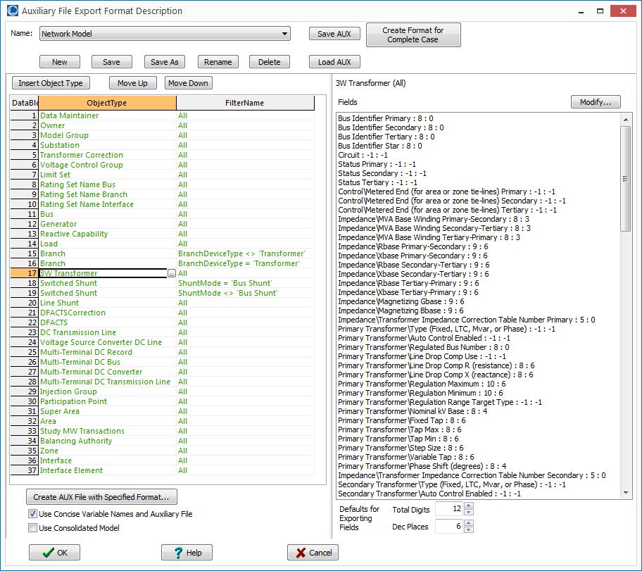
79 78
Record Specification and File Format for Specifying Contingency Definitions and Remedial Actions Schemes
 Record Specification and File Format for Specifying Contingency Definitions and Remedial Actions Schemes Date : October 22, 2013 December 6, 2013 January 21, 2015 August 28, 2015 Prepared by : James Weber,
PowerWorld Simulator Version 20 Auxiliary File Format Description for Specifying Contingency Definitions and Remedial Actions
 PowerWorld Simulator Version 20 Auxiliary File Format Description for Specifying Contingency Definitions and Remedial Actions Date : December 1, 2015 (Simulator Version 19 Release) Last Update : Prepared
PowerWorld s Experience Using Real-Time Power System Models
 PowerWorld s Experience Using Real-Time Power System Models Presented by: James Weber, Ph.D. Director of Software Development February 28, 2018 2001 South First Street Champaign, Illinois 61820 (217) 384-6330
Auxiliary Files I PowerWorld Corporation
 Auxiliary Files PowerWorld Simulator data can be stored and edited in a text file format A scripting language is available for modifying data and automatically running PowerWorld Simulator commands The
Changes to Difference Case Tool in Simulator 20
 Changes to Difference Case Tool in Simulator 20 Presented by: Jamie Weber, Ph.D. Director of Software Development 2001 South First Street Champaign, Illinois 61820 +1 (217) 384.6330 support@powerworld.com
Dynamic Load Models in PowerWorld Simulator
 Dynamic Load Models in PowerWorld Simulator Jamie Weber (weber@powerworld.com) Director of Software Development 2001 South First Street Champaign, Illinois 61820 +1 (217) 384.6330 support@powerworld.com
Record Specification and File Format for Specifying Contingency Definitions and Remedial Actions Schemes
 Record Specification and File Format for Specifying Contingency Definitions and Remedial Actions Schemes Matt Davis matt@powerworld.com 217 384 6330 Ext. 20 2001 South First Street Champaign, Illinois
PowerWorld Simulator Data Checks
 PowerWorld Simulator Data Checks Jamie Weber, Ph.D. Director of Software Development 2001 South First Street Champaign, Illinois 61820 +1 (217) 384.6330 support@powerworld.com http://www.powerworld.com
Specifics of Implementation
 Specifics of Implementation Defining Criteria Filtering ModelCondition ModelFilter Conditional Contingency Actions CriteriaStatus = POSTCHECK ModelExpression (lookup tables) RemedialAction Complexity of
What s New in Simulator Version 18
 What s New in Simulator Version 18 PowerWorld Client Conference May 20, 2014 Jamie Weber weber@powerworld.com 217 384 6330 ext 13 2001 South First Street Champaign, Illinois 61820 +1 (217) 384.6330 support@powerworld.com
Modeling of RAS and Relays in Power Flow Contingency Analysis. Jamie Weber
 Modeling of RAS and Relays in Power Flow Contingency Analysis Jamie Weber weber@powerworld.com 217 384 6330 ext. 13 2001 South First Street Champaign, Illinois 61820 +1 (217) 384.6330 support@powerworld.com
PowerWorld Simulator 17 What s New in Simulator. Mark Laufenberg
 PowerWorld Simulator 17 What s New in Simulator Mark Laufenberg lauf@powerworld.com 217 384 6330 ext. 10 2001 South First Street Champaign, Illinois 61820 +1 (217) 384.6330 support@powerworld.com http://www.powerworld.com
Steady-State Power System Security Analysis with PowerWorld Simulator
 Steady-State Power System Security Analysis with PowerWorld Simulator 2001 South First Street Champaign, Illinois 61820 +1 (217) 384.6330 support@powerworld.com http://www.powerworld.com Available Transfer
Transient Stability Analysis with PowerWorld Simulator
 Transient Stability Analysis with PowerWorld Simulator T14: Large-Scale Simulation Examples 2001 South First Street Champaign, Illinois 61820 +1 (217) 384.6330 support@powerworld.com http://www.powerworld.com
SMUD Model Data Requirements & Reporting Procedures MOD VERSION 1.2
 SMUD Model Data Requirements & Reporting Procedures MOD-032-1 VERSION 1.2 NOVEMBER 10, 2015 1 TABLE OF CONTENTS INTRODUCTION... 2 1.1 Purpose... 2 1.2 Audience... 3 1.3 Process Overview... 3 Figure 1-1:
Introduction to PowerWorld Simulator: Interface and Common Tools
 Introduction to PowerWorld Simulator: Interface and Common Tools I1: The PowerWorld Simulator Case Editor 2001 South First Street Champaign, Illinois 61820 +1 (217) 384.6330 support@powerworld.com http://www.powerworld.com
Multi User Operations Training Simulator. Trainers Workshop Reception
 : Multi User Operations Training Simulator Trainers Workshop Reception July 26, 2012 2001 South First Street Champaign, Illinois 61820 +1 (217) 384.6330 Scott R. Dahman, P.E. scott@powerworld.com http://www.powerworld.com
Transmission Register PTO Admin User Manual. Version 1.0
 Transmission Register PTO Admin User Manual Version 1.0 Table of Contents 1. INTRODUCTION... 3 1.1. Purpose...3 1.2. Scope...3 1.3. Definitions...3 2. COMPONENTS HOMEPAGE... 6 2.1. Find Components...6
4.1.1 Generator Owner Transmission Owner that owns synchronous condenser(s)
") A. Introduction 1. Title: Verification and Data Reporting of Generator Real and Reactive Power Capability and Synchronous Condenser Reactive Power Capability 2. Number: MOD-025-2 3. Purpose: To ensure
A. Introduction 1. Title: Verification and Data Reporting of Generator Real and Reactive Power Capability and Synchronous Condenser Reactive Power Capability 2. Number: MOD-025-2 3. Purpose: To ensure
Tutorials. Tutorial: Creating a New Case Page 1 of 13
 Tutorial: Creating a New Case Page 1 of 13 This procedure describes how to create a simple power system model using PowerWorld Simulator. This procedure was developed for use with version 13 and later
WECC Criterion MOD-(11 and 13)-WECC-CRT-1.1
-WECC-CRT-1.1") WECC Criterion MOD-(11 and 13)-WECC-CRT-1.1 A. Introduction 1. Title: Steady State and Dynamic Data Requirements 2. Number: MOD-(11 and 13)-WECC-CRT-1.1 3. Purpose: To establish the consistent data requirements
WECC Criterion MOD-(11 and 13)-WECC-CRT-1.1 A. Introduction 1. Title: Steady State and Dynamic Data Requirements 2. Number: MOD-(11 and 13)-WECC-CRT-1.1 3. Purpose: To establish the consistent data requirements
Proposal for Development and Use of Node- Breaker Topology Representations for Offline and Real-time Study Models November 12, 2013
 Proposal for Development and Use of Node- Breaker Topology Representations for Offline and Real-time November 12, 2013 Rationale Background Interconnection wide powerflow and dynamics cases are currently
SIEMENS POWER SYSTEM SIMULATION FOR ENGINEERS (PSS/E) LAB2 INTRODUCTION TO SLIDER BINARY (*.sld) FILES
 LAB2 INTRODUCTION TO SLIDER BINARY (*.sld) FILES") SIEMENS POWER SYSTEM SIMULATION FOR ENGINEERS (PSS/E) LAB2 INTRODUCTION TO SLIDER BINARY (*.sld) FILES Power Systems Simulations Colorado State University PURPOSE: The purpose of this lab is to introduce
SIEMENS POWER SYSTEM SIMULATION FOR ENGINEERS (PSS/E) LAB2 INTRODUCTION TO SLIDER BINARY (*.sld) FILES Power Systems Simulations Colorado State University PURPOSE: The purpose of this lab is to introduce
4.1.1 Generator Owner Transmission Owner that owns synchronous condenser(s)
") A. Introduction 1. Title: Verification and Data Reporting of Generator Real and Reactive Power Capability and Synchronous Condenser Reactive Power Capability 2. Number: MOD-025-2 3. Purpose: To ensure
A. Introduction 1. Title: Verification and Data Reporting of Generator Real and Reactive Power Capability and Synchronous Condenser Reactive Power Capability 2. Number: MOD-025-2 3. Purpose: To ensure
Access Intermediate
 Access 2013 - Intermediate 103-134 Advanced Queries Quick Links Overview Pages AC124 AC125 Selecting Fields Pages AC125 AC128 AC129 AC131 AC238 Sorting Results Pages AC131 AC136 Specifying Criteria Pages
ETAP PowerStation 4.0
 ETAP PowerStation 4.0 User Guide Copyright 2001 Operation Technology, Inc. All Rights Reserved This manual has copyrights by Operation Technology, Inc. All rights reserved. Under the copyright laws, this
What s New in Simulator Version 20
 What s New in Simulator Version 20 Prepared by Caroline Marzinzik caroline@powerworld.com 217 384 6330 Ext. 12 2001 South First Street Champaign, Illinois 61820 +1 (217) 384.6330 What s New in Version
Small Generator Interconnection System Impact Study Report. Completed For Q0047
 Small Generator Interconnection Completed For Q0047 Proposed Interconnection PacifiCorp s Existing Goshen Rigby 69 kv Line March 7, 2005 1.0 Description of the Generation Facility Q0047 ( Interconnection
LAB1 INTRODUCTION TO PSS/E EE461: POWER SYSTEMS COLORADO STATE UNIVERSITY
 LAB1 INTRODUCTION TO PSS/E EE461: POWER SYSTEMS COLORADO STATE UNIVERSITY PURPOSE: The purpose of this lab is to introduce PSS/E. This lab will introduce the following aspects of PSS/E: Introduction to
Access Intermediate
 Access 2010 - Intermediate 103-134 Advanced Queries Quick Links Overview Pages AC116 AC117 Selecting Fields Pages AC118 AC119 AC122 Sorting Results Pages AC125 AC126 Specifying Criteria Pages AC132 AC134
WECC and Base Case Development Process D E C E M B E R 1 2, J O N AT H A N Y O U N G
 WECC and Base Case Development Process D E C E M B E R 1 2, 2 0 1 8 J O N AT H A N Y O U N G How Base Cases are Built for the Biennial Transmission Expansion Plan? Study Assumptions & Case Selection Case
Dispatcher Training Simulator (DTS) JOB AIDE
 JOB AIDE") APPLICABILITY: System Operators or anyone operating the system via Peak s GE- Alstom. I. Purpose To provide System Operators a job aid on using the DTS, particularly within the restoration drill. II. Introduction
APPLICABILITY: System Operators or anyone operating the system via Peak s GE- Alstom. I. Purpose To provide System Operators a job aid on using the DTS, particularly within the restoration drill. II. Introduction
Generation Interconnection Feasibility Study Report
 Project 76 Generation Interconnection Feasibility Study Report December 21, 2007 Electric Transmission Planning Table of Contents Table of Contents... 2 Executive Summary... 3 Network Resource Interconnection
Revised Generation Interconnection Impact Study Report. For. Queue Position 31 ( Interconnection Customer )
") Revised Generation Interconnection Impact Study Report For Queue Position 31 ( Interconnection Customer ) September 22, 2004 1 Generation Interconnection System Impact Study Report I. Revision of Original
Revised Generation Interconnection Impact Study Report For Queue Position 31 ( Interconnection Customer ) September 22, 2004 1 Generation Interconnection System Impact Study Report I. Revision of Original
Breeding Guide. Customer Services PHENOME-NETWORKS 4Ben Gurion Street, 74032, Nes-Ziona, Israel
 Breeding Guide Customer Services PHENOME-NETWORKS 4Ben Gurion Street, 74032, Nes-Ziona, Israel www.phenome-netwoks.com Contents PHENOME ONE - INTRODUCTION... 3 THE PHENOME ONE LAYOUT... 4 THE JOBS ICON...
Joint Transmission Planning Base Case Preparation Process
 California Independent System Operator & Southern California Edison Joint Transmission Planning Base Case Preparation Process NERC Reliability Standard MOD-032-1 Version 1.2 August 31, 2017 INTENTIONALLY
RTDMS CAISO TRAINING SESSION
 Consortium for Electric Reliability Technology Solutions Real-Time Dynamics Monitoring System (RTDMS ) RTDMS CAISO TRAINING SESSION January 31, 2006 Manu Parashar & Jim Dyer Electric Power Group (EPG)
GiftWorks Import Guide Page 2
 Import Guide Introduction... 2 GiftWorks Import Services... 3 Import Sources... 4 Preparing for Import... 9 Importing and Matching to Existing Donors... 11 Handling Receipting of Imported Donations...
What s New in Simulator Version 20
 What s New in Simulator Version 20 Prepared by Caroline Marzinzik caroline@powerworld.com 217 384 6330 Ext. 12 2001 South First Street Champaign, Illinois 61820 +1 (217) 384.6330 What s New in Version
Requirements for Data for Power System Modeling and Analysis (MOD-032-1) Arizona Public Service Company
 Arizona Public Service Company") Requirements for Data for Power System Modeling and Analysis (MOD-032-1) Arizona Public Service Company December 29, 2016 APS Requirements for Data for Power System Modeling and Analysis Table of Contents
Requirements for Data for Power System Modeling and Analysis (MOD-032-1) Arizona Public Service Company December 29, 2016 APS Requirements for Data for Power System Modeling and Analysis Table of Contents
Auxiliary File Format for Simulator 13
 Auxiliary File Format for Simulator 13 Last Updated: December 14, 2007 PowerWorld Corporation 2001 South First St Champaign, IL 61820 (217) 384-6330 http://www.powerworld.com info@powerworld.com Table
Using Basic Formulas 4
 Using Basic Formulas 4 LESSON SKILL MATRIX Skills Exam Objective Objective Number Understanding and Displaying Formulas Display formulas. 1.4.8 Using Cell References in Formulas Insert references. 4.1.1
i-pcgrid Workshop 2014 PG&E Order No. 754 Analysis: Protection
 i-pcgrid Workshop 2014 PG&E Order No. 754 Analysis: Protection 1 Process PG&E Order No. 754 Analysis Receive Bus List from Planning that Meet the Criteria in Table A Protection Computes Actual Clearing
POWER WORLD LAB MANUAL
 POWER WORLD LAB MANUAL Power world is a great powerful tool for solving power flows. Solving a power system is a little different from circuit analysis. Instead of being given voltages at certain nodes
STATISTICAL TECHNIQUES. Interpreting Basic Statistical Values
 STATISTICAL TECHNIQUES Interpreting Basic Statistical Values INTERPRETING BASIC STATISTICAL VALUES Sample representative How would one represent the average or typical piece of information from a given
Formulas and Functions
 Conventions used in this document: Keyboard keys that must be pressed will be shown as Enter or Ctrl. Controls to be activated with the mouse will be shown as Start button > Settings > System > About.
XXXXX XXXX Wind Generation Project
 A subsidiary of Pinnacle West Capital Corporation XXXXX XXXX Wind Generation Project XXXX XXXXX XXXXXXX Co., Inc. Interconnection System Impact Study Final Report Prepared By Arizona Public Service Company
PRC Coordination of Protection Systems for Performance During Faults
 PRC-027-1 Coordination of Protection Systems for Performance During Faults A. Introduction 1. Title: Coordination of Protection Systems for Performance During Faults 2. Number: PRC-027-1 3. Purpose: To
Feasibility Study on Load Flow and Short Circuit Project
 Feasibility Study on Load Flow and Short Circuit Project 101813-01 Prepared by: Transmission Planning Department Cleco Corporation, Inc. 2180 St. Landry Hwy P.O. Box 70 St. Landry, LA 71367 Final November
University of California, Santa Cruz Baskin Engineering School Electrical Engineering Department
 Lab-2 Intro, rev2.0, page 1 University of California, Santa Cruz Baskin Engineering School Electrical Engineering Department Laboratory 2 Tutorial Addendum Introduction to POWERWORLD Simulator EE175L Power
Evolution of Control for the Power Grid
 Evolution of Control for the Power Grid Anjan Bose Washington State University Pullman, WA, USA PaiFest In Honor of Prof. M. A. Pai Urbana-Champaign, IL October 15, 2015 The Past (before 1960s) Hard
Interconnection of Navajo-Gallup Water Supply Project Electrical Transmission Facilities. Non-Tariff System Impact Study
 Interconnection of Navajo-Gallup Water Supply Project Electrical Transmission Facilities Non-Tariff System Impact Study March 204 Prepared by: Utility System Efficiencies, Inc (USE) Under Contract with:
January 22, The Honorable Kimberly D. Bose Secretary Federal Energy Regulatory Commission 888 First Street, N.E. Washington, D.C.
 California Independent System Operator Corporation January 22, 2013 The Honorable Kimberly D. Bose Secretary Federal Energy Regulatory Commission 888 First Street, N.E. Washington, D.C. 20426 Re: California
LAB5 MULTIPLE ACCC REPORT WESTERN AREA POWER ADMINISTRATION
 LAB5 MULTIPLE ACCC REPORT WESTERN AREA POWER ADMINISTRATION PURPOSE: The purpose of this lab is to gain an understanding of how to modify the contingency file, monitor file, and the subsystem files previously
Caroline Marzinzik. CMPLDW Support in PowerWorld Simulator ext. 12
 CMPLDW Support in PowerWorld Simulator Caroline Marzinzik caroline@powerworld.com 217 398 2340 ext. 12 2001 South First Street Champaign, Illinois 61820 +1 (217) 384.6330 support@powerworld.com http://www.powerworld.com
LAB6 ADDITION OF GENERATION EE461: POWER SYSTEMS COLORADO STATE UNIVERSITY
 LAB6 ADDITION OF GENERATION EE461: POWER SYSTEMS COLORADO STATE UNIVERSITY PURPOSE: The purpose of this lab is to introduce a wind farm into a base case and analyze the effects using PSS/E. Introduction
ETAP PowerStation 4.0
 ETAP PowerStation 4.0 User Guide Copyright 2001 Operation Technology, Inc. All Rights Reserved This manual has copyrights by Operation Technology, Inc. All rights reserved. Under the copyright laws, this
This section is maintained by the drafting team during the development of the standard and will be removed when the standard becomes effective.
 Standard Development Timeline This section is maintained by the drafting team during the development of the standard and will be removed when the standard becomes effective. Development Steps Completed
Standard Development Timeline
 Standard Development Timeline This section is maintained by the drafting team during the development of the standard and will be removed when the standard becomes effective. Description of Current Draft
PacifiCorp Transmission Technical Workshop
 PacifiCorp Transmission Technical Workshop RFP Attachment 20 February 22, 2012 Presented by PacifiCorp Transmission PacifiCorp Transmission Update Integrated Resource Plan Attachment 20 Point of Receipt
PracticeMaster Report Writer Guide
 Copyright 2014-2015 Software Technology, Inc. 1621 Cushman Drive Lincoln, NE 68512 (402) 423-1440 Tabs3.com Tabs3, PracticeMaster, and the "pinwheel" symbol ( ) are registered trademarks of Software Technology,
Technology Innovation Delivering Value to BPA Organized, Disciplined, Focused
 B O N N E V I L L E P O W E R A D M I N I S T R A T I O N Technology Innovation Delivering Value to BPA Organized, Disciplined, Focused Keeping the Lights on for the Long Term The Basics Bonneville Power
1. Introduction to Microsoft Excel
 1. Introduction to Microsoft Excel A spreadsheet is an online version of an accountant's worksheet, which can automatically do most of the calculating for you. You can do budgets, analyze data, or generate
BC HYDRO REAL TIME OPERATIONS SYSTEM OPERATING ORDER 7T - 50
 BC HYDRO REAL TIME OPERATIONS SYSTEM OPERATING ORDER 7T - 50 VOLTAGE STABILITY OPERATING LIMITS AND PROCEDURES FOR USING THE REAL TIME VOLTAGE STABILITY APPLICATION (RTVSA) Supercedes 7T-50 dated 02 May
Data Import Guide DBA Software Inc.
 Contents 3 Table of Contents 1 Introduction 4 2 Data Import Instructions 5 3 Data Import - Customers 10 4 Data Import - Customer Contacts 16 5 Data Import - Delivery Addresses 19 6 Data Import - Suppliers
Universal Format Plug-in User s Guide. Version 10g Release 3 (10.3)
") Universal Format Plug-in User s Guide Version 10g Release 3 (10.3) UNIVERSAL... 3 TERMINOLOGY... 3 CREATING A UNIVERSAL FORMAT... 5 CREATING A UNIVERSAL FORMAT BASED ON AN EXISTING UNIVERSAL FORMAT...
Universal Format Plug-in User s Guide Version 10g Release 3 (10.3) UNIVERSAL... 3 TERMINOLOGY... 3 CREATING A UNIVERSAL FORMAT... 5 CREATING A UNIVERSAL FORMAT BASED ON AN EXISTING UNIVERSAL FORMAT...
DRAFT Reliability Guideline: Modeling Distributed Energy Resources in Dynamic Load Models
 DRAFT Reliability Guideline: Modeling Distributed Energy Resources in Dynamic Load Models Problem Statement With the proliferation of distributed energy resources (DER), Transmission Planners must adapt
1. Introduction to Microsoft Excel
 1. Introduction to Microsoft Excel A spreadsheet is an online version of an accountant's worksheet, which can automatically do most of the calculating for you. You can do budgets, analyze data, or generate
Section 4 General Factorial Tutorials
 Section 4 General Factorial Tutorials General Factorial Part One: Categorical Introduction Design-Ease software version 6 offers a General Factorial option on the Factorial tab. If you completed the One
Level 2, 3 and 4 Interconnection Application for Certified, Inverter Based Generating Facilities Not Greater than 2MW
 Level 2, 3 and 4 Interconnection Application for Certified, Inverter Based Generating Facilities Not Greater than 2MW The Customer Generator applicant ("Applicant") hereby makes application to the T &
FSEDIT Procedure Windows
 25 CHAPTER 4 FSEDIT Procedure Windows Overview 26 Viewing and Editing Observations 26 How the Control Level Affects Editing 27 Scrolling 28 Adding Observations 28 Entering and Editing Variable Values 28
Introduction to Generation Availability Data System (GADS) Wind Reporting
 Wind Reporting") Introduction to Generation Availability Data System (GADS) Wind Reporting Registration and Reporting Fundamentals Donna Pratt, Performance Analysis Manager-Data Analytics NERC Webinar April 26, 2017 Topics
Introduction to Generation Availability Data System (GADS) Wind Reporting Registration and Reporting Fundamentals Donna Pratt, Performance Analysis Manager-Data Analytics NERC Webinar April 26, 2017 Topics
Introduction: Model Relationships Network Model Overview Example Commercial Model Overview Component Hierarchy & Definitions Example of Structure
 1 2 3 Introduction: Model Relationships Network Model Overview Example Commercial Model Overview Component Hierarchy & Definitions Example of Structure MISO Functions Served by the Network Model by the
System Protection and Control Subcommittee
 Power Plant and Transmission System Protection Coordination GSU Phase Overcurrent (51T), GSU Ground Overcurrent (51TG), and Breaker Failure (50BF) Protection System Protection and Control Subcommittee
Transient Stability Analysis with PowerWorld Simulator
 Transient Stability Analysis with PowerWorld Simulator 2001 South First Street Champaign, Illinois 61820 +1 (217) 384.6330 support@powerworld.com http://www.powerworld.com Multiple Contingencies In most
VISUAL GUIDE to. RX Scripting. for Roulette Xtreme - System Designer 2.0. L J Howell UX Software Ver. 1.0
 VISUAL GUIDE to RX Scripting for Roulette Xtreme - System Designer 2.0 L J Howell UX Software 2009 Ver. 1.0 TABLE OF CONTENTS INTRODUCTION...ii What is this book about?... iii How to use this book... iii
Use Case Task 1-?: Convert Low Side Load Rollover from EMS application to Multi-Section Line Model used by the Planning application(s)
") Use Case Task 1-?: Low Side Load Rollover Specifications Page 1 Use Case Task 1-?: Convert Low Side Load Rollover from EMS application to Multi-Section Line Model by the application(s) 1 Summary: Convert
Use Case Task 1-?: Low Side Load Rollover Specifications Page 1 Use Case Task 1-?: Convert Low Side Load Rollover from EMS application to Multi-Section Line Model by the application(s) 1 Summary: Convert
Study Guide. PCIC 3 B2 GS3- Key Applications-Excel. Copyright 2010 Teknimedia Corporation
 Study Guide PCIC 3 B2 GS3- Key Applications-Excel Copyright 2010 Teknimedia Corporation Teknimedia grants permission to any licensed owner of PCIC 3 B GS3 Key Applications-Excel to duplicate the contents
Data Types and Variables in C language
 Data Types and Variables in C language Basic structure of C programming To write a C program, we first create functions and then put them together. A C program may contain one or more sections. They are
From: Laura Manz, Vice President of Market & Infrastructure Development
 California Independent System Operator Corporation Memorandum To: ISO Board of Governors From: Laura Manz, Vice President of Market & Infrastructure Development Date: May 8, 2009 Re: Decision for Conditional
LESSON 1. A C program is constructed as a sequence of characters. Among the characters that can be used in a program are:
 LESSON 1 FUNDAMENTALS OF C The purpose of this lesson is to explain the fundamental elements of the C programming language. C like other languages has all alphabet and rules for putting together words
CS201 - Introduction to Programming Glossary By
 CS201 - Introduction to Programming Glossary By #include : The #include directive instructs the preprocessor to read and include a file into a source code file. The file name is typically enclosed with
d-file Language Reference Manual
 Erwin Polio Amrita Rajagopal Anton Ushakov Howie Vegter d-file Language Reference Manual COMS 4115.001 Thursday, October 20, 2005 Fall 2005 Columbia University New York, New York Note: Much of the content
Memorandum. This memorandum requires Committee action.
 California Independent System Operator Corporation Memorandum To: ISO Operations Committee From: Dariush Shirmohammadi, Director of Regional Transmission - South Armando Perez, VP, Planning & Infrastructure
Unofficial Comment Form Project Disturbance Monitoring
 Unofficial Comment Form Project 2007-11 Disturbance Monitoring Please DO NOT use this form for submitting comments. Please use the electronic form to submit comments on the Standard Authorization Request
A guide on PowerWorld Simulator ver. 12.0
 A guide on PowerWorld Simulator ver. 12.0 This tutorial has been developed to aid the undergraduate and graduate students at the University of Cyprus to learn the basic features of PowerWorld. It is not
2018 General Rate Case. Transmission & Distribution (T&D) Volume 3 R System Planning
 Volume 3 R System Planning") Application No.: Exhibit No.: Witnesses: A.1-0- SCE-0, Vol. 0 R E. Takayesu A (U -E) 01 General Rate Case Transmission & Distribution (T&D) Volume R System Planning Before the nd Errata Public Utilities
Application No.: Exhibit No.: Witnesses: A.1-0- SCE-0, Vol. 0 R E. Takayesu A (U -E) 01 General Rate Case Transmission & Distribution (T&D) Volume R System Planning Before the nd Errata Public Utilities
Introduction to Internet of Things Prof. Sudip Misra Department of Computer Science & Engineering Indian Institute of Technology, Kharagpur
 Introduction to Internet of Things Prof. Sudip Misra Department of Computer Science & Engineering Indian Institute of Technology, Kharagpur Lecture - 23 Introduction to Arduino- II Hi. Now, we will continue
Access Intermediate
 Access 2010 - Intermediate (103-134) Building Access Databases Notes Quick Links Building Databases Pages AC52 AC56 AC91 AC93 Building Access Tables Pages AC59 AC67 Field Types Pages AC54 AC56 AC267 AC270
Date adopted/approved 02/08/2013 Custodian (entity responsible for maintenance and upkeep) Data Exchange Work Group. Web URL: Previous name/number
 Data Exchange Work Group. Web URL: Previous name/number") Document name Category Guideline for WECC Operations Network Node: Responsibilities and Procedures ( ) Regional Reliability Standard ( ) Regional Criteria ( ) Policy (X) Guideline ( ) Report or other (
Document name Category Guideline for WECC Operations Network Node: Responsibilities and Procedures ( ) Regional Reliability Standard ( ) Regional Criteria ( ) Policy (X) Guideline ( ) Report or other (
LAB4 AC CONTINGENCY CALCULATION REPORT WESTERN AREA POWER ADMINISTRATION
 LAB4 AC CONTINGENCY CALCULATION REPORT WESTERN AREA POWER ADMINISTRATION PURPOSE: The purpose of this lab is to introduce the contingency file, monitor file, and the subsystem files. This lab will explain
( ) Regional Reliability Standard ( ) Regional Criteria ( ) Policy (x) Guideline ( ) Report or other ( ) Charter M&VWG. Physical location: Web URL:
 Regional Reliability Standard ( ) Regional Criteria ( ) Policy (x) Guideline ( ) Report or other ( ) Charter M&VWG. Physical location: Web URL:") Document name Cross-Current Compensation Model Specification Category Document date June 18, 2015 Adopted/approved by ( ) Regional Reliability Standard ( ) Regional Criteria ( ) Policy (x) Guideline (
Document name Cross-Current Compensation Model Specification Category Document date June 18, 2015 Adopted/approved by ( ) Regional Reliability Standard ( ) Regional Criteria ( ) Policy (x) Guideline (
Mirage. Language Reference Manual. Image drawn using Mirage 1.1. Columbia University COMS W4115 Programming Languages and Translators Fall 2006
 Mirage Language Reference Manual Image drawn using Mirage 1.1 Columbia University COMS W4115 Programming Languages and Translators Fall 2006 Prof. Stephen Edwards Team Members: Abhilash I ai2160@columbia.edu
Approval...6. Current Revision...7. Introduction... 8 About PJM Manuals... 8 About This Manual... 8 Using This Manual...9
 PJM Manual 07: PJM Protection Standards Revision: 3 Effective Date: May 24, 2018 Prepared by System Planning Division Transmission Planning Department PJM 2018 Table of Contents Table of Contents Approval...6
Features of C. Portable Procedural / Modular Structured Language Statically typed Middle level language
 1 History C is a general-purpose, high-level language that was originally developed by Dennis M. Ritchie to develop the UNIX operating system at Bell Labs. C was originally first implemented on the DEC
Functional Programming in Haskell Prof. Madhavan Mukund and S. P. Suresh Chennai Mathematical Institute
 Functional Programming in Haskell Prof. Madhavan Mukund and S. P. Suresh Chennai Mathematical Institute Module # 02 Lecture - 03 Characters and Strings So, let us turn our attention to a data type we have
NERC Event Analysis Update Webinar. Hassan Hamdar Chair, Event Analysis Subcommittee October 20, 2016
 NERC Event Analysis Update Webinar Hassan Hamdar Chair, Event Analysis Subcommittee October 20, 2016 Webinar Agenda ERO Event Analysis Process Update Lesson Learned Presentation from Entity ERO Lessons
Maximizing protection coordination with self-healing technology
 Supersedes December 2011 Daniel P. Roth, Distribution Automation Technical Manager, Eaton s Cooper Power Systems Abstract Much of the Smart Grid initiative includes the installation of new recloser and
Phasor Technology Research Road Map to Improve Grid Reliability and Market Efficiency. Presented to TAC on April 5, 2005 and PAC on April 22, 2005
 Phasor Technology Research Road Map to Improve Grid Reliability and Market Efficiency Presented to TAC on April 5, 2005 and PAC on April 22, 2005 Background Power Grid has evolved from a vertically integrated
Modeling and Simulation in XENDEE
 Modeling and Simulation in XENDEE IEEE 34 Node Test Feeder Shammya Saha Graduate Research Assistant Electrical Engineering Ira A. Fulton School of Engineering Arizona State University shammya.saha@asu.edu