Chapter 3 Loaders and Linkers
|
|
|
- Bartholomew Conley
- 5 years ago
- Views:
Transcription

1 Chapter 3 Loaders and Linkers Three fundamental processes: Loading brings the object program into memory for execution. Relocation modifies the object program so that it can be loaded at an address different from the location originally specified. Linking combines two or more separate object programs and supplies the information needed to allow references between them. A loader is a system program that performs the loading function. Many loaders also support relocation and linking. Some systems have a linker to perform the linking operations and a separate loader to handle relocation and loading. 3.1 Introduction The most fundamental functions of a loader bringing an object program into memory and starting its execution Design of an Absolute Loader An example object program is shown in Fig 3.1(a). Written by WWF 1
 As each Text record is read, the object code it contains is moved to the indicated address in memory.")
2 For a simple absolute loader, all functions are accomplished in a single pass as follows: 1) The Header record of object programs is checked to verify that the correct program has been presented for loading. 2) As each Text record is read, the object code it contains is moved to the indicated address in memory. 3) When the End record is encountered, the loader jumps to the specified address to begin execution of the loaded program. Fig 3.1(b) shows a representation of the program from Fig 3.1(a) after loading. Fig 3.2 shows an algorithm for the absolute loader we have discussed. Written by WWF 2
3 It is very important to realize that in Fig 3.1(a), each printed character represents one byte of the object program record. In Fig 3.1(b), on the other hand, each printed character represents one hexadecimal digit in memory (a half-byte). Therefore, to save space and execution time of loaders, most machines store object programs in a binary form, with each byte of object code stored as a single byte in the object program A Simple Bootstrap Loader When a computer is first turned on or restarted, a special type of absolute loader, called a bootstrap loader, is executed. This bootstrap loads the first program to be run by the computer usually an operating system. Fig 3.3 shows the source code for our bootstrap loader. The bootstrap itself begins at address 0 in the memory. Written by WWF 3
 The object code from device F1 is always loaded into consecutive bytes of memory, starting at address 80.")
4 Note: each byte of object code to be loaded is represented on device F1 as two hexadecimal digits just as it is in a Text record of a SIC object program. 1) The object code from device F1 is always loaded into consecutive bytes of memory, starting at address 80. The Written by WWF 4
5 main loop of the bootstrap keeps the address of the next memory location to be loaded in register X. 2) After all of the object code from device F1 has been loaded, the bootstrap jumps to address 80, which begins the execution of the program that was loaded. Much of the work of the bootstrap loader is performed by the subroutine GETC. GETC is used to read and convert a pair of characters from device F1 representing 1 byte of object code to be loaded. For example, two bytes =C D H converting to one byte D8 H. The resulting byte is stored at the address currently in register X, using STCH instruction that refers to location 0 using indexed addressing. The TIXR instruction is then used to add 1 to the value in X. 3.2 Machine-Dependent Loader Features The absolute loader has several potential disadvantages. One of the most obvious is the need for the programmer to specify the actual address at which it will be loaded into memory. Writing absolute programs also makes it difficult to use subroutine libraries efficiently. This could not be done effectively if all of the subroutines had pre-assigned absolute addresses. The need for program relocation is an indirect consequence of the change to larger and more powerful computers. The way relocation is implemented in a loader is also dependent upon machine characteristics. Written by WWF 5
6 3.2.1 Relocation Two methods for specifying relocation as part of the object program. The first method: A Modification record (The format is given in Section ) is used to describe each part of the object code that must be changed when the program is relocated. Fig 3.4 shows a SIC/XE program we use to illustrate this first method of specifying relocation. Written by WWF 6

7 Written by WWF 7

8 Most of the instructions in this program use relative or immediate addressing. The only portions of the assembled program that contain actual addresses are the extended format instructions on lines 15, 35, and 65. Thus these are the only items whose values are affected by relocation. Fig 3.5 displays the object program corresponding to the source in Fig 3.4. Each Modification record specifies the starting address and length of the field whose value is to be altered. It then describes the modification to be performed. In this example, all modifications add the value of the symbol COPY, which represents the starting address of the program. The Modification record is not well suited for use with all machine architectures. Consider, for example, the program in Fig 3.6. This is a relocatable program written for standard version for SIC. Written by WWF 8

9 The important difference between this example and the one in Fig 3.4 is that the standard SIC machine does not use relative addressing. In this program the addresses in all the instructions except RSUB must modified when the program is Written by WWF 9

10 relocated. This would require 31 Modification records, which results in an object program more than twice as large as the one in Fig 3.5. The second method: Fig 3.7 shows this method applied to our SIC program example. There are no Modification records. The Text records are the same as before except that there is a relocation bit associated with each word of object code. Since all SIC instructions occupy one word, this means that there is one relocation bit for each possible instruction. The relocation bits are gathered together into a bit mask following the length indicator in each Text record. In Fig 3.7 this mask is represented (in character form) as three hexadecimal digits. If the relocation bit corresponding to a word of object code is set to 1, the program s starting address is to be added to this word when the program is relocated. A bit value of 0 indicates that no modification is necessary. If a Text record contains fewer than 12 words of object code, the bits corresponding to unused words are set to 0. Written by WWF 10
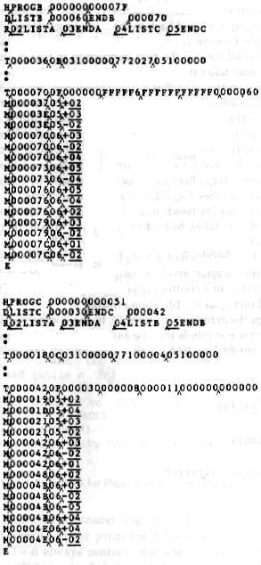
11 For example, the bit mask FFC (representing the bit string ) in the first Text record specifies that all 10 words of object code are to be modified during relocation. Example: note that the LDX instruction on line 210 (Fig 3.6) begins a new Text record. If it were placed in the preceding Text record, it would not be properly aligned to correspond to a relocation bit because of the 1-byte data value generated from line Program Linking Consider the three (separately assembled) programs in Fig 3.8, each of which consists of a single control section. Written by WWF 11
12 Consider first the reference marked REF1. For the first program (PROGA), (1) REF1 is simply a reference to a label within the program. (2) It is assembled in the usual way as a PC relative instruction. (3) No modification for relocation or linking is necessary. In PROGB, the same operand refers to an external symbol. (1) The assembler uses an extended-format instruction with address field set to (2) The object program for PROGB (Fig 3.9) contains a Modification record instructing the loader to add the value of the symbol LISTA to this address field when the program is linked. Written by WWF 12
13 For PROGC, REF1 is handled in exactly the same way. The reference marked REF2 is processed in a similar manner. REF3 is an immediate operand whose value is to be the difference between ENDA and LISTA (that is, the length of the list in bytes). In PROGA, the assembler has all of the information necessary to compute this value. During the assembly of PROGB (and PROGC), the values of the labels are unknown. In these programs, the expression must be assembled as an external reference (with two Modification records) even though the final result will be an absolute value independent of the locations at which the programs are loaded. Consider REF4. The assembler for PROGA can evaluate all of the Written by WWF 13

14 expression in REF4 except for the value of LISTC. This results in an initial value of H and one Modification record. The same expression in PROGB contains no terms that can be evaluated by the assembler. The object code therefore contains an initial value of and three Modification records. For PROGC, the assembler can supply the value of LISTC relative to the beginning of the program (but not the actual address, which is not known until the program is loaded). The initial value of this data word contains the relative address of LISTC ( H). Modification records instruct the loader to add the beginning address of the program (i.e., the value of PROGC), to add the value of ENDA, and to subtract the value of LISTA. Fig 3.10(a) shows these three programs as they might appear in memory after loading and linking. PROGA has been loaded starting at address 4000, with PROGB and PROGC immediately following. Written by WWF 14
15 For example, the value for reference REF4 in PROGA is located at address 4054 (the beginning address of PROGA plus 0054). Fig 3.10(b) shows the details of how this value is computed. The initial value (from the Text record) is To this is added the address assigned to LISTC, which 4112 (the beginning address of PROGC plus 30) Algorithm and Data Structures for a Linking Loader The algorithm for a linking loader is considerably more complicated than the absolute loader algorithm discussed in Section 3.1. A linking loader usually makes two passes over its input, just as an assembler does. In terms of general function, Written by WWF 15
16 the two passes of a linking loader are quite similar to the two passes of an assembler: Pass 1 assigns addresses to all external symbols. Pass 2 performs the actual loading, relocation, and linking. The main data structure needed for our linking loader is an external symbol table ESTAB. This table, which is analogous to SYMTAB in our assembler algorithm, is used to store the name and address of each external symbol in the set of control sections being loaded. A hashed organization is typically used for this table. Two other important variables are PROGADDR (program load address) and CSADDR (control section address). PROGADDR is the beginning address in memory where the linked program is to be loaded. Its value is supplied to the loader by the OS. CSADDR contains the starting address assigned to the control section currently being scanned by the loader. This value is added to all relative addresses within the control section to convert them to actual addresses. The algorithm is presented in Fig During Pass 1 (Fig 3.11(a)), the loader is concerned only with Header and Define record types in the control sections. Written by WWF 16
17 1) The beginning load address for the linked program (PROGADDR) is obtained from the OS. This becomes the starting address (CSADDR) for the first control section in the input sequence. 2) The control section name from Header record is entered into ESTAB, with value given by CSADDR. All external symbols appearing in the Define record for the control section are also entered into ESTAB. Their addresses are obtained by adding the value specified in the Define record to CSADDR. 3) When the End record is read, the control section length Written by WWF 17
18 CSLTH (which was saved from the End record) is added to CSADDR. This calculation gives the starting address for the next control section in sequence. At the end of Pass 1, ESTAB contains all external symbols defined in the set of control sections together with the address assigned to each. Many loaders include as an option the ability to print a load map that shows these symbols and their addresses. For the example of Figs 3.9 and 3.10, such a load map might look like as shown on the top of page 143. Pass 2 (Fig 3.11(b)) of our loader performs the actual loading, relocation, and linking of the program. Written by WWF 18
19 1) As each Text record is read, the object code is moved to the specified address (plus the current value of CSADDR). 2) When a Modification record is encountered, the symbol whose value is to be used for modification is looked up in ESTAB. 3) This value is then added to or subtracted from the indicated location in memory. 4) The last step performed by the loader is usually the transferring of control to the loaded program to begin execution. The End record for each control section may contain the address of the first instruction in that control section to be executed. Our loader takes this as the transfer point to begin execution. If more than one control section specifies a transfer address, the loader arbitrarily uses the last one encountered. If no control section contains a transfer address, the loader uses the beginning of the linked program (i.e., PROGADDR) as the transfer point. Normally, a transfer address would be placed in the End record for a main program, but not for a subroutine. This algorithm can be made more efficient. Assign a reference number, which is used (instead of the symbol name) in Modification records, to each external symbol referred to in a control section. Suppose we always assign the reference number 01 to the control section name. Fig 3.12 shows the object programs from 3.9 with this Written by WWF 19

20 change. Written by WWF 20
21 3.3 Machine-Independent Loader Features Loading and linking are often thought of as OS service functions. Therefore, most loaders include fewer different features than are found in a typical assembler. They include the use of an automatic library search process for handling external reference and some common options that can be selected at the time of loading and linking Automatic Library Search Many linking loaders can automatically incorporate routines from a subprogram library into the program being loaded. Linking loaders that support automatic library search must keep track of external symbols that are referred to, but not defined, in the primary input to the loader. At the end of Pass 1, the symbols in ESTAB that remain undefined represent unresolved external references. The loader searches the library or libraries specified for routines that contain the definitions of these symbols, and processes the subroutines found by this search exactly as if they had been part of the primary input stream. Note that the subroutines fetched from a library in this way may themselves contain external references. It is therefore necessary to repeat the library search process until all references are resolved. If unresolved external references remain after the library search is completed, these must be treated as errors Loader Options Many loaders allow the user to specify options that modify the standard processing described in Section 3.2. Written by WWF 21
22 Typical loader option 1: allows the selection of alternative sources of input. Ex., INCLUDE program-name (library-name) might direct the loader to read the designated object program from a library and treat it as if it were part of the primary loader input. Loader option 2: allows the user to delete external symbols or entire control sections. Ex., DELETE csect-name might instruct the loader to delete the named control section(s) from the set of programs being loaded. CHANGE name1, name2 might cause the external symbol name1 to be changed to name2 wherever it appears in the object programs. Loader option 3: involves the automatic inclusion of library routines to satisfy external references. Ex., LIBRARY MYLIB Such user-specified libraries are normally searched before the standard system libraries. This allows the user to use special versions of the standard routines. NOCALL STDDEV, PLOT, CORREL To instruct the loader that these external references are to remain unresolved. This avoids the overhead of loading and linking the unneeded routines, and saves the memory space that would otherwise be required. 3.4 Loader Design Options Linking loaders perform all linking and relocation at load Written by WWF 22
23 time. There are two alternatives: Linkage editors, which perform linking prior to load time, and dynamic linking, in which the linking function is performed at execution time. Precondition: The source program is first assembled or compiled, producing an object program. A linking loader performs all linking and relocation operations, including automatic library search if specified, and loads the linked program directly into memory for execution. A linkage editor produces a linked version of the program (load module or executable image), which is written to a file or library for later execution. The essential difference between a linkage editor and a linking loader is illustrated in Fig Written by WWF 23
24 3.4.1 Linkage Editors The linkage editor performs relocation of all control sections relative to the start of the linked program. Thus, all items that need to be modified at load time have values that are relative to the start of the linked program. This means that the loading can be accomplished in one pass with no external symbol table required. If a program is to be executed many times without being reassembled, the use of a linkage editor substantially reduces the overhead required. Linkage editors can perform many useful functions besides simply preparing an object program for execution. Ex., a typical sequence of linkage editor commands used: INCLUDE PLANNER (PROGLIB) DELETE PROJECT {delete from existing PLANNER} INCLUDE PROJECT (NEWLIB) {include new version} REPLACE PLANNER (PROGLIB) Linkage editors can also be used to build packages of subroutines or other control sections that are generally used together. This can be useful when dealing with subroutine libraries that support high-level programming languages. Linkage editors often include a variety of other options and commands like those discussed for linking loaders. Compared to linking loaders, linkage editors in general tend to offer more flexibility and control Dynamic Linking Linkage editors perform linking operations before the program is loaded for execution. Linking loaders perform these same operations at load Written by WWF 24
25 time. Dynamic linking, dynamic loading, or load on call postpones the linking function until execution time: a subroutine is loaded and linked to the rest of the program when it is first called. Dynamic linking is often used to allow several executing programs to share one copy of a subroutine or library, ex. run-time support routines for a high-level language like C. With a program that allows its user to interactively call any of the subroutines of a large mathematical and statistical library, all of the library subroutines could potentially be needed, but only a few will actually be used in any one execution. Dynamic linking can avoid the necessity of loading the entire library for each execution except those necessary subroutines. Fig 3.14 illustrates a method in which routines that are to be dynamically loaded must be called via an OS service request. Written by WWF 25

26 Written by WWF 26
27 Fig 3.14(a): Instead of executing a JSUB instruction referring to an external symbol, the program makes a load-and-call service request to OS. The parameter of this request is the symbolic name of the routine to be called. Fig 3.14(b): OS examines its internal tables to determine whether or not the routine is already loaded. If necessary, the routine is loaded from the specified user or system libraries. Fig 3.14(c): Control is then passed from OS to the routine being called Fig 3.14(d): When the called subroutine completes it processing, it returns to its caller (i.e., OS). OS then returns control to the program that issued the request. Fig 3.14(e): If a subroutine is still in memory, a second call to it may not require another load operation. Control may simply be passed from the dynamic loader to the called routine Bootstrap Loaders Given an idle computer with no program in memory, how do we get things started? On some computers, an absolute loader program is permanently resident in a read-only memory (ROM). When some hardware signal occurs, the machine begins to execute this ROM program. This is referred to as a bootstrap loader. 3.5 Implementation Examples (Skip) Written by WWF 27
UNIT III LOADERS AND LINKERS
 UNIT III LOADERS AND LINKERS INTRODUCTION Loader is a system program that performs the loading function. Many loaders also support relocation and linking. Some systems have a linker (linkage editor) to
Chapter 3 Loaders and Linkers
 Chapter 3 Loaders and Linkers Outline 3.1 Basic Loader Functions 3.2 Machine-Dependent Loader Features 3.3 Machine-Independent Loader Features 3.4 Loader Design Options 3.5 Implementation Examples Introduction
Loaders. Systems Programming. Outline. Basic Loader Functions
 Loaders Systems Programming Chapter 3 Linkers and Loaders A loader is a system program that performs the loading function. many also support relocation & linking others have a separate linker and loader
Chapter 3 Loaders and Linkers
 Chapter 3 Loaders and Linkers Outline 3.1 Basic Loader Functions 3.2 Machine-Dependent Loader Features 3.3 Machine-Independent Loader Features 3.4 Loader Design Options 3.5 Implementation Examples Introduction
UNIT III - LOADERS AND LINKERS
 3.1 Introduction to Loaders UNIT III - LOADERS AND LINKERS A loader is the part of an operating system that is responsible for loading programs into memory and prepares them for execution. Loading a program
Chapter 3: Loaders and Linkers
 Department of Electr rical Eng ineering, Chapter 3: Loaders and Linkers 王振傑 (Chen-Chieh Wang) ccwang@mail.ee.ncku.edu.tw ncku edu 3.1 Basic Loader Functions 3.1.1 Design of an Absolute Loader 3.1.2 A Simple
Prepared By : Ms. Sanchari Saha ( Asst. Professor) Department : Computer Science & Engineering
 Department : Computer Science & Engineering") Subject Name: System Software Subject Code: 10CS52 Prepared By : Ms. Sanchari Saha ( Asst. Professor) Department : Computer Science & Engineering Date : 20-10-2014 UNIT-4 LOADERS & LINKERS Engineered for
Subject Name: System Software Subject Code: 10CS52 Prepared By : Ms. Sanchari Saha ( Asst. Professor) Department : Computer Science & Engineering Date : 20-10-2014 UNIT-4 LOADERS & LINKERS Engineered for
UNIT III LOADERS AND LINKERS PART A
 PART A UNIT III LOADERS AND LINKERS 1. Define Absolute Loader and Bootstrap Loader. The loader, which is used only for loading but not for relocation or linking is known as absolute loader. e.g. Bootstrap
This contains the following three processes, and they are,
 Chapter 3 Loaders and Linkers This Chapter gives you Basic Loader Functions Machine-Dependent Loader Features Machine-Independent Loader Features Loader Design Options Implementation Examples 30 Introduction
3.3 Machine-Independent Loader Features
 3.3 Machine-Independent Loader Features Loading and linking are often thought of as operating system service functions. Machine independent loader features: 3.3.1 Automatic Library Search 3.3.2 Loader
1.Program to find factorial of a given number
 1.Program to find factorial of a given number DATA SEGMENT X DW 06H FACT DW? DATA ENDS CODE SEGMENT ASSUME CS:CODE,DS:DATA START: MOV AX,DATA MOV DS,AX MOV AX,01H ;Set the value of AX as 01H. MOV CX,X
LOADERS AND LINKERS 1. BASIC LOADER FUNCTIONS 2. DESIGN OF AN ABSOLUTE LOADER 3. A SIMPLE BOOTSTRAP LOADER 4. MACHINE DEPENDENT LOADER FEATURES
 UIT III LOADERS AD LIKERS 1. BASIC LOADER FUCTIOS 2. DESIG OF A ABSOLUTE LOADER 3. A SIMPLE BOOTSTRAP LOADER 4. MACHIE DEPEDET LOADER FEATURES 5. RELOCATIO 6. PROGRAM LIKIG 7. ALGORITHM AD DATA STRUCTURES
Chapter 3 Loaders and Linkers -- Machine-Dependent Loader Feature
 Chapter 3 Loaders and Linkers -- Machine-Dependent Loader Feature Motivation Shortcoming of an absolute loader Programmer needs to specify the actual address at which it will be loaded into memory. It
Chapter 3 Loaders and Linkers -- Loader Design Options
 Chapter 3 Loaders and Linkers -- Loader Design Options Loaders Linkage editor Linking before loading Dynamic linking Linking at the execution time Bootstrap loader Linkage editors Difference between a
Gechstudentszone.wordpress.com
 CHAPTER -2 2.1 Basic Assembler Functions: The basic assembler functions are: ASSEMBLERS-1 Translating mnemonic language code to its equivalent object code. Assigning machine addresses to symbolic labels.
UNIT 1: MACHINE ARCHITECTURE
 VTU QUESTION PAPER SOLUTION UNIT 1: MACHINE ARCHITECTURE 1. a) Give the target address generated for the following machine instruction: (i) 032600h (ii) 03C300h (iii) 0310C303h if (B)=006000, (PC)=003000,
Chapter 2. Assembler Design
 Chapter 2 Assembler Design Assembler is system software which is used to convert an assembly language program to its equivalent object code. The input to the assembler is a source code written in assembly
CS2304-SYSTEM SOFTWARE 2 MARK QUESTION & ANSWERS. UNIT I INTRODUCTION
 CS2304-SYSTEM SOFTWARE 2 MARK QUESTION & ANSWERS. UNIT I INTRODUCTION 1. Define System Software. System software consists of a variety of programs that supports the operations of a computer. Eg. Compiler,
UNIT I - INTRODUCTION
 UNIT I - INTRODUCTION 1. Define system software. It consists of variety of programs that supports the operation of the computer. This software makes it possible for the user to focus on the other problems
MODULE 5 LINKERS AND LOADERS
 MODULE 5 LINKERS AND LOADERS Execution phases The execution of a program involves 4 steps:- 1) Translation Converting source program to object modules. The assemblers and compilers fall under the category
Machine dependent Assembler Features
 Machine dependent Assembler Features Assembler Features Machine Dependent Assembler Features Instruction formats and addressing modes (SIC/XE) Program relocation Machine Independent Assembler Features
 UNIT II ASSEMBLERS www.noyesengine.com www.technoscriptz.com 1 1. BASIC ASSEMBLER FUNCTIONS 2. A SIMPLE SIC ASSEMBLER 3. ASSEMBLER ALGORITHM AND DATA STRUCTURES 4. MACHINE DEPENDENT ASSEMBLER FEATURES
UNIT 1: MACHINE ARCHITECTURE
 VTU QUESTION PAPER SOLUTION UNIT 1: MACHINE ARCHITECTURE 1. Give the target address generated for the following machine instruction: (i) 032600h (ii) 03C300h (iii) 0310C303h if (B)=006000, (PC)=003000,
Chapter 1: Background
 Chapter 1: Background Hsung-Pin Chang Department of Computer Science National Chung Hsing University Outline 1.1 Introduction 1.2 System Software and Machine Architecture 1.3 The Simplified Instructional
AS-2883 B.Sc.(Hon s)(fifth Semester) Examination,2013 Computer Science (PCSC-503) (System Software) [Time Allowed: Three Hours] [Maximum Marks : 30]
![AS-2883 B.Sc.(Hon s)(fifth Semester) Examination,2013 Computer Science (PCSC-503) (System Software) [Time Allowed: Three Hours] [Maximum Marks : 30]](/thumbs/80/81792243.jpg "AS-2883 B.Sc.(Hon s)(fifth Semester) Examination,2013 Computer Science (PCSC-503) (System Software) [Time Allowed: Three Hours] [Maximum Marks : 30]") AS-2883 B.Sc.(Hon s)(fifth Semester) Examination,2013 Computer Science (PCSC-503) (System Software) [Time Allowed: Three Hours] [Maximum Marks : 30] Note: Question Number 1 is compulsory. Marks : 10X1
AS-2883 B.Sc.(Hon s)(fifth Semester) Examination,2013 Computer Science (PCSC-503) (System Software) [Time Allowed: Three Hours] [Maximum Marks : 30] Note: Question Number 1 is compulsory. Marks : 10X1
2.1. Basic Assembler Functions:
 2.1. Basic Assembler Functions: The basic assembler functions are: Translating mnemonic language code to its equivalent object code. Assigning machine addresses to symbolic labels. SOURCE PROGRAM ASSEMBLER
 Introduction SIC, RISC & CISC 0. Introduction to Systems Programming This course aims at: Understanding what is going on behind the scenes The design and implementation of system software, such as Assemblers
Chapter 2 Assemblers Machine-Dependent Assembler Features
 Chapter 2 Assemblers -- 2.2 Machine-Dependent Assembler Features Outline Instruction format and addressing mode Program relocation Instruction format and addressing mode PC-relative or Base-relative addressing
Assemblers. System Software by Leland L. Beck. Chapter 2
 Assemblers System Software by Leland L. Beck Chapter 2 1 Role of Assembler Source Program Assembler Object Code Linker Executable Code Loader 2 Chapter 2 -- Outline Basic Assembler Functions Machine-dependent
Gechstudentszone.wordpress.com
 UNIT - 1 MACHINE ARCHITECTURE 11 Introduction: The Software is set of instructions or programs written to carry out certain task on digital computers It is classified into system software and application
Compile: compiler. Load: loader. compiler linker loader memory. source object load code module module 2
 Part III Storage Management Chapter 8: Memory Management Fall 2010 1 Address Generation Address generation has three stages: Compile: compiler Link: linker or linkage editor Load: loader compiler linker
Unit 2 -- Outline. Basic Assembler Functions Machine-dependent Assembler Features Machine-independent Assembler Features Assembler Design Options
 Unit 2 -- Outline Basic Assembler Functions Machine-dependent Assembler Features Machine-independent Assembler Features Assembler Design Options Introduction to Assemblers Fundamental functions translating
CS2422 Assembly Language & System Programming
 CS2422 Assembly Language & System Programming November 30, 2006 Today s Topic Assembler: Basic Functions Section 2.1 of Beck s System Software book. Reading Assignment: pages 43-52. Role of Assembler Source
UNIT II ASSEMBLERS. Figure Assembler
 2.1 Basic assembler functions UNIT II ASSEMBLERS Assembler Assembler which converts assembly language programs into object files. Object files contain a combination of machine instructions, data, and information
Computer Hardware and System Software Concepts
 Computer Hardware and System Software Concepts Introduction to concepts of System Software/Operating System Welcome to this course on Computer Hardware and System Software Concepts 1 RoadMap Introduction
CSCI341. Lecture 22, MIPS Programming: Directives, Linkers, Loaders, Memory
 CSCI341 Lecture 22, MIPS Programming: Directives, Linkers, Loaders, Memory REVIEW Assemblers understand special commands called directives Assemblers understand macro commands Assembly programs become
Chapter 1. Introduction
 Chapter 1 Introduction This Chapter gives you System Software & Machine Architecture The Simplified Instructional Computer SIC and SIC/XE Traditional (CISC) Machines - Complex Instruction Set Computers
國立嘉義大學資訊工程學系系統程式期中考考卷
 國立嘉義大學資訊工程學系系統程式期中考考卷 學號 : 姓名 : 1. Please write the content in the lines. (25%) PROGB START EXTDEF B1, B2 EXTREF A1 LDA B1 +LDA A1 STA B1 +STA A1 B1 WORD 7 BUF RESB 1 B2 RESW 1 MAX EQU 1 END H^PROGA^^
Compiler, Assembler, and Linker
 Compiler, Assembler, and Linker Minsoo Ryu Department of Computer Science and Engineering Hanyang University msryu@hanyang.ac.kr What is a Compilation? Preprocessor Compiler Assembler Linker Loader Contents
INTERNAL TEST (SCHEME AND SOLUTION)
") PES Institute of Technology, Bangalore South Campus (Formerly PES School of Engineering) (Hosur Road, 1KM before Electronic City, Bangalore-560 100) Dept of MCA INTERNAL TEST (SCHEME AND SOLUTION) 1 Subject
PES Institute of Technology, Bangalore South Campus (Formerly PES School of Engineering) (Hosur Road, 1KM before Electronic City, Bangalore-560 100) Dept of MCA INTERNAL TEST (SCHEME AND SOLUTION) 1 Subject
Chapter 9 Memory Management Main Memory Operating system concepts. Sixth Edition. Silberschatz, Galvin, and Gagne 8.1
 Chapter 9 Memory Management Main Memory Operating system concepts. Sixth Edition. Silberschatz, Galvin, and Gagne 8.1 Chapter 9: Memory Management Background Swapping Contiguous Memory Allocation Segmentation
PESIT Bangalore South Campus Department of MCA Course Information for. System Programming (13MCA24)
") PESIT Bangalore South Campus Department of MCA Course Information for System Programming (13MCA24) 1.GENERAL INFORMATION Academic Year: 2015 Semester(s): 2 nd Title Code Duration (hrs) Lectures 48 Hrs
PESIT Bangalore South Campus Department of MCA Course Information for System Programming (13MCA24) 1.GENERAL INFORMATION Academic Year: 2015 Semester(s): 2 nd Title Code Duration (hrs) Lectures 48 Hrs
TRB-COMPUTER INSTRUCTOR COMPUTER SCIENCE UNIT IV. SYSTEM SOFTWARE 10% DISCOUNT FOR ALL PGTRB MATERIALS WITH QUESTION BANK.
 N COACHING CENTRE-TRICHY- TRB- COMPUTER INSTRUCTOR-COMPUTER SCIENCE STUDY MATERIAL-CONTACT: 822006 2017 N TRB-COMPUTER INSTRUCTOR COMPUTER SCIENCE UNIT IV SYSTEM SOFTWARE 10% DISCOUNT FOR ALL PGTRB MATERIALS
Memory Management (1) Memory Management
 Memory Management") EECS 3221 Operating System Fundamentals No.8 Memory Management (1) Prof. Hui Jiang Dept of Electrical Engineering and Computer Science, York University Memory Management A program usually resides on a
EECS 3221 Operating System Fundamentals No.8 Memory Management (1) Prof. Hui Jiang Dept of Electrical Engineering and Computer Science, York University Memory Management A program usually resides on a
Memory Management (1) Memory Management. CPU vs. memory. No.8. Prof. Hui Jiang Dept of Electrical Engineering and Computer Science, York University
 Memory Management. CPU vs. memory. No.8. Prof. Hui Jiang Dept of Electrical Engineering and Computer Science, York University") EECS 3221 Operating System Fundamentals No.8 Memory Management (1) Prof. Hui Jiang Dept of Electrical Engineering and Computer Science, York University Memory Management A program usually resides on a
EECS 3221 Operating System Fundamentals No.8 Memory Management (1) Prof. Hui Jiang Dept of Electrical Engineering and Computer Science, York University Memory Management A program usually resides on a
DHANALAKSHMI SRINIVASAN INSTITUTE OF RESEARCH AND TECHNOLOGY SIRUVACHUR, PERAMBALUR DEPARTMENT OF COMPUTER SCIENCE AND ENGINEERING
 DHANALAKSHMI SRINIVASAN INSTITUTE OF RESEARCH AND TECHNOLOGY SIRUVACHUR, PERAMBALUR 621113. DEPARTMENT OF COMPUTER SCIENCE AND ENGINEERING CS2304- SYSTEM SOFTWARE PART-B QUESTIONS 1. EXPLAIN THE ARCHITECTURE
Memory Management. Reading: Silberschatz chapter 9 Reading: Stallings. chapter 7 EEL 358
 Memory Management Reading: Silberschatz chapter 9 Reading: Stallings chapter 7 1 Outline Background Issues in Memory Management Logical Vs Physical address, MMU Dynamic Loading Memory Partitioning Placement
Assembler Design Options
 Assembler Design Options One and Multi-Pass Assembler So far, we have presented the design and implementation of a two-pass assembler. Here, we will present the design and implementation of One-pass assembler
PESIT SOUTHCAMPUS 10CS52: SYSTEM SOFTWARE QUESTION BANK
 CS52: SYSTEM SOFTWARE QUESTION BANK Chapter1: MACHINE ARCHITECTURE OBJECTIVE: Main Objective is to Know about the system software and architecture of Various Machines Like SIC, SIC/XE and Programming examples
CS2422 Assembly Language & System Programming
 CS2422 Assembly Language & System Programming December 7, 2006 Today s Topic Assembler: Machine Dependent Features SIC/XE Program Relocation Modification Records in an Object File. Study Guide Sections
PRINCIPLES OF COMPILER DESIGN UNIT I INTRODUCTION TO COMPILERS
 Objective PRINCIPLES OF COMPILER DESIGN UNIT I INTRODUCTION TO COMPILERS Explain what is meant by compiler. Explain how the compiler works. Describe various analysis of the source program. Describe the
Chapter 1 Background. Professor Gwan-Hwan Hwang Dept. Computer Science and Information Engineering National Taiwan Normal University
 Chapter 1 Background Professor Gwan-Hwan Hwang Dept. Computer Science and Information Engineering National Taiwan Normal University 9/17/2009 1 Outlines 1.1 Introduction 1.2 System Software and Machine
CSI 402 Lecture 5 (Assemblers Continued) 5 1 / 18
 5 1 / 18") CSI 402 Lecture 5 (Assemblers Continued) 5 1 / 18 Program Relocation Example 1: Consider the SIC instruction LDA THREE Assume the following: The START directive specifies the value 100 (decimal) The LC
CSI 402 Lecture 5 (Assemblers Continued) 5 1 / 18 Program Relocation Example 1: Consider the SIC instruction LDA THREE Assume the following: The START directive specifies the value 100 (decimal) The LC
Memory Management. Frédéric Haziza Spring Department of Computer Systems Uppsala University
 Memory Management Frédéric Haziza Department of Computer Systems Uppsala University Spring 2008 Operating Systems Process Management Memory Management Storage Management Compilers Compiling
Lecture #2 January 30, 2004 The 6502 Architecture
 Lecture #2 January 30, 2004 The 6502 Architecture In order to understand the more modern computer architectures, it is helpful to examine an older but quite successful processor architecture, the MOS-6502.
Building a Runnable Program and Code Improvement. Dario Marasco, Greg Klepic, Tess DiStefano
 Building a Runnable Program and Code Improvement Dario Marasco, Greg Klepic, Tess DiStefano Building a Runnable Program Review Front end code Source code analysis Syntax tree Back end code Target code
CS370: Operating Systems [Spring 2017] Dept. Of Computer Science, Colorado State University
![CS370: Operating Systems [Spring 2017] Dept. Of Computer Science, Colorado State University](/thumbs/83/87505258.jpg "CS370: Operating Systems [Spring 2017] Dept. Of Computer Science, Colorado State University") Frequently asked questions from the previous class survey CS 370: OPERATING SYSTEMS [MEMORY MANAGEMENT] Matrices in Banker s algorithm Max, need, allocated Shrideep Pallickara Computer Science Colorado
Frequently asked questions from the previous class survey CS 370: OPERATING SYSTEMS [MEMORY MANAGEMENT] Matrices in Banker s algorithm Max, need, allocated Shrideep Pallickara Computer Science Colorado
Addresses in the source program are generally symbolic. A compiler will typically bind these symbolic addresses to re-locatable addresses.
 1 Memory Management Address Binding The normal procedures is to select one of the processes in the input queue and to load that process into memory. As the process executed, it accesses instructions and
Chapter 9 Memory Management
 Contents 1. Introduction 2. Computer-System Structures 3. Operating-System Structures 4. Processes 5. Threads 6. CPU Scheduling 7. Process Synchronization 8. Deadlocks 9. Memory Management 10. Virtual
The Assembly Language Level. Chapter 7
 The Assembly Language Level Chapter 7 Definitions Translator Converts user program to another language Source language Language of original program Target language Language into which source code is converted
! What is main memory? ! What is static and dynamic allocation? ! What is segmentation? Maria Hybinette, UGA. High Address (0x7fffffff) !
 !") Memory Questions? CSCI [4 6]730 Operating Systems Main Memory! What is main memory?! How does multiple processes share memory space?» Key is how do they refer to memory addresses?! What is static and dynamic
Memory Questions? CSCI [4 6]730 Operating Systems Main Memory! What is main memory?! How does multiple processes share memory space?» Key is how do they refer to memory addresses?! What is static and dynamic
12: Memory Management
 12: Memory Management Mark Handley Address Binding Program goes through multiple steps from compilation to execution. At some stage, addresses in the program must be bound to physical memory addresses:
CS1203-SYSTEM SOFTWARE UNIT I-INTRODUCTION
 CS1203-SYSTEM SOFTWARE UNIT I-INTRODUCTION 1. Define system software. It consists of variety of programs that supports the operation of the computer. This software makes it possible for the user to focus
COMPILERS BASIC COMPILER FUNCTIONS
 COMPILERS BASIC COMPILER FUNCTIONS A compiler accepts a program written in a high level language as input and produces its machine language equivalent as output. For the purpose of compiler construction,
Main Memory (Part I)
") Main Memory (Part I) Amir H. Payberah amir@sics.se Amirkabir University of Technology (Tehran Polytechnic) Amir H. Payberah (Tehran Polytechnic) Main Memory 1393/8/5 1 / 47 Motivation and Background Amir
Main Memory (Part I) Amir H. Payberah amir@sics.se Amirkabir University of Technology (Tehran Polytechnic) Amir H. Payberah (Tehran Polytechnic) Main Memory 1393/8/5 1 / 47 Motivation and Background Amir
9.1 Background. In Chapter 6, we showed how the CPU can be shared by a set of processes. As a result of
 Chapter 9 MEMORY MANAGEMENT In Chapter 6, we showed how the CPU can be shared by a set of processes. As a result of CPU scheduling, we can improve both the utilization of the CPU and the speed of the computer's
Objectives. ICT106 Fundamentals of Computer Systems Topic 8. Procedures, Calling and Exit conventions, Run-time Stack Ref: Irvine, Ch 5 & 8
 Objectives ICT106 Fundamentals of Computer Systems Topic 8 Procedures, Calling and Exit conventions, Run-time Stack Ref: Irvine, Ch 5 & 8 To understand how HLL procedures/functions are actually implemented
MIPS (SPIM) Assembler Syntax
 Assembler Syntax") MIPS (SPIM) Assembler Syntax Comments begin with # Everything from # to the end of the line is ignored Identifiers are a sequence of alphanumeric characters, underbars (_), and dots () that do not begin
MIPS (SPIM) Assembler Syntax Comments begin with # Everything from # to the end of the line is ignored Identifiers are a sequence of alphanumeric characters, underbars (_), and dots () that do not begin
Chapter 8: Memory Management. Operating System Concepts with Java 8 th Edition
 Chapter 8: Memory Management 8.1 Silberschatz, Galvin and Gagne 2009 Background Program must be brought (from disk) into memory and placed within a process for it to be run Main memory and registers are
CSE 4/521 Introduction to Operating Systems. Lecture 12 Main Memory I (Background, Swapping) Summer 2018
 Summer 2018") CSE 4/521 Introduction to Operating Systems Lecture 12 Main Memory I (Background, Swapping) Summer 2018 Overview Objective: 1. To provide a detailed description of various ways of organizing memory hardware.
CSE 4/521 Introduction to Operating Systems Lecture 12 Main Memory I (Background, Swapping) Summer 2018 Overview Objective: 1. To provide a detailed description of various ways of organizing memory hardware.
Memory Management. Memory Management
 Memory Management Most demanding di aspect of an operating system Cost has dropped. Consequently size of main memory has expanded enormously. Can we say that we have enough still. Swapping in/out. Memory
UNIT-II. Part-2: CENTRAL PROCESSING UNIT
 Page1 UNIT-II Part-2: CENTRAL PROCESSING UNIT Stack Organization Instruction Formats Addressing Modes Data Transfer And Manipulation Program Control Reduced Instruction Set Computer (RISC) Introduction:
Chapter 12. CPU Structure and Function. Yonsei University
 Chapter 12 CPU Structure and Function Contents Processor organization Register organization Instruction cycle Instruction pipelining The Pentium processor The PowerPC processor 12-2 CPU Structures Processor
The A ssembly Assembly Language Level Chapter 7 1
 The Assembly Language Level Chapter 7 1 Contemporary Multilevel Machines A six-level l computer. The support method for each level is indicated below it.2 Assembly Language Level a) It is implemented by
3. Memory Management
 Principles of Operating Systems CS 446/646 3. Memory Management René Doursat Department of Computer Science & Engineering University of Nevada, Reno Spring 2006 Principles of Operating Systems CS 446/646
Operating Systems. Designed and Presented by Dr. Ayman Elshenawy Elsefy
 Operating Systems Designed and Presented by Dr. Ayman Elshenawy Elsefy Dept. of Systems & Computer Eng.. AL-AZHAR University Website : eaymanelshenawy.wordpress.com Email : eaymanelshenawy@yahoo.com Reference
Compiler Design. Computer Science & Information Technology (CS) Rank under AIR 100
 Rank under AIR 100") GATE- 2016-17 Postal Correspondence 1 Compiler Design Computer Science & Information Technology (CS) 20 Rank under AIR 100 Postal Correspondence Examination Oriented Theory, Practice Set Key concepts,
GATE- 2016-17 Postal Correspondence 1 Compiler Design Computer Science & Information Technology (CS) 20 Rank under AIR 100 Postal Correspondence Examination Oriented Theory, Practice Set Key concepts,
Outlook. Background Swapping Contiguous Memory Allocation Paging Structure of the Page Table Segmentation Example: The Intel Pentium
 Main Memory Outlook Background Swapping Contiguous Memory Allocation Paging Structure of the Page Table Segmentation Example: The Intel Pentium 2 Backgound Background So far we considered how to share
Chapter 8 & Chapter 9 Main Memory & Virtual Memory
 Chapter 8 & Chapter 9 Main Memory & Virtual Memory 1. Various ways of organizing memory hardware. 2. Memory-management techniques: 1. Paging 2. Segmentation. Introduction Memory consists of a large array
 UNIT -1 1.1 OVERVIEW OF LANGUAGE PROCESSING SYSTEM 1.2 Preprocessor A preprocessor produce input to compilers. They may perform the following functions. 1. Macro processing: A preprocessor may allow a
CS399 New Beginnings. Jonathan Walpole
 CS399 New Beginnings Jonathan Walpole Memory Management Memory Management Memory a linear array of bytes - Holds O.S. and programs (processes) - Each cell (byte) is named by a unique memory address Recall,
Language Translation. Compilation vs. interpretation. Compilation diagram. Step 1: compile. Step 2: run. compiler. Compiled program. program.
 Language Translation Compilation vs. interpretation Compilation diagram Step 1: compile program compiler Compiled program Step 2: run input Compiled program output Language Translation compilation is translation
CS370 Operating Systems
 CS370 Operating Systems Colorado State University Yashwant K Malaiya Spring 2018 L16 Deadlocks, Main Memory Slides based on Text by Silberschatz, Galvin, Gagne Various sources 1 1 Where we are: Deadlocks
Subroutine Linkage Wheeler Jump control program
 Subroutine Linkage We now begin discussion of subroutine linkages for simple subroutines without large argument blocks. With the mechanisms discussed in this lecture, one can use either global variables
8086 ALP TOOLS (CH 2) CHAPTER 2
 CHAPTER 2") 1 CHAPTER 2 In this chapter, we shall discuss the Assembly Language Program development tools, PC memory structure and Assembler directives. Books to be Referred: 1. Microprocessors and Interfacing 2nd
1 CHAPTER 2 In this chapter, we shall discuss the Assembly Language Program development tools, PC memory structure and Assembler directives. Books to be Referred: 1. Microprocessors and Interfacing 2nd
M2 Instruction Set Architecture
 M2 Instruction Set Architecture Module Outline Addressing modes. Instruction classes. MIPS-I ISA. Translating and starting a program. High level languages, Assembly languages and object code. Subroutine
CS311 Lecture: The Architecture of a Simple Computer
 CS311 Lecture: The Architecture of a Simple Computer Objectives: July 30, 2003 1. To introduce the MARIE architecture developed in Null ch. 4 2. To introduce writing programs in assembly language Materials:
ORG ; TWO. Assembly Language Programming
 Dec 2 Hex 2 Bin 00000010 ORG ; TWO Assembly Language Programming OBJECTIVES this chapter enables the student to: Explain the difference between Assembly language instructions and pseudo-instructions. Identify
Module 3. DEADLOCK AND STARVATION
 This document can be downloaded from www.chetanahegde.in with most recent updates. 1 Module 3. DEADLOCK AND STARVATION 3.1 PRINCIPLES OF DEADLOCK Deadlock can be defined as the permanent blocking of a
Part I: Translating & Starting a Program: Compiler, Linker, Assembler, Loader. Lecture 4
 Part I: a Program: Compiler, Linker, Assembler, Loader Lecture 4 Program Translation Hierarchy C program Com piler Assem bly language program Assem bler Object: Machine language module Object: Library
Memory and multiprogramming
 Memory and multiprogramming COMP342 27 Week 5 Dr Len Hamey Reading TW: Tanenbaum and Woodhull, Operating Systems, Third Edition, chapter 4. References (computer architecture): HP: Hennessy and Patterson
System V Application Binary Interface Linux Extensions Version 0.1
 System V Application Binary Interface Linux Extensions Version 0.1 Edited by H.J. Lu 1 November 28, 2018 1 hongjiu.lu@intel.com Contents 1 About this Document 4 1.1 Related Information.........................
CIT 595 Spring System Software: Programming Tools. Assembly Process Example: First Pass. Assembly Process Example: Second Pass.
 System Software: Programming Tools Programming tools carry out the mechanics of software creation within the confines of the operating system and hardware environment Linkers & Loaders CIT 595 Spring 2010
CSE2421 Systems1 Introduction to Low-Level Programming and Computer Organization
 Spring 2013 CSE2421 Systems1 Introduction to Low-Level Programming and Computer Organization Kitty Reeves TWRF 8:00-8:55am 1 Compiler Drivers = GCC When you invoke GCC, it normally does preprocessing,
Assembler. Lecture 8 CS301
 Assembler Lecture 8 CS301 Discussion Given the following function header, int foo(int a, int b); what will be on the stack before any of the calculations in foo are performed? Assume foo() calls some other
Generating Programs and Linking. Professor Rick Han Department of Computer Science University of Colorado at Boulder
 Generating Programs and Linking Professor Rick Han Department of Computer Science University of Colorado at Boulder CSCI 3753 Announcements Moodle - posted last Thursday s lecture Programming shell assignment
COMPILER DESIGN LEXICAL ANALYSIS, PARSING
 COMPILER DESIGN LEXICAL ANALYSIS, PARSING 1. Which of the following system program forgoes the production of object code to generate absolute machine code and load it into the Physical main storage location
Administrivia. Deadlock Prevention Techniques. Handling Deadlock. Deadlock Avoidance
 Administrivia Project discussion? Last time Wrapped up deadlock Today: Start memory management SUNY-BINGHAMTON CS35 SPRING 8 LEC. #13 1 Handling Deadlock Deadlock Prevention Techniques Prevent hold and
Topics. 2 Introduction to Common Object File Format 2-3
 MSP430 Family Introduction to COFF Format Topics 2 Introduction to Common Object File Format 2-3 2.1 Sections 2-4 2.2 How the Assembler Handles Sections 2-6 2.2.1 Uninitialized Sections 2-6 2.2.2 Initialized
14.7 Dynamic Linking. Building a Runnable Program
 14 Building a Runnable Program 14.7 Dynamic Linking To be amenable to dynamic linking, a library must either (1) be located at the same address in every program that uses it, or (2) have no relocatable