Verilog Design Entry, Synthesis, and Behavioral Simulation
|
|
|
- Roy Norris
- 5 years ago
- Views:
Transcription
 8.2i.")
1 PURPOSE - This lab will present a brief overview of a typical design flow and then will start to walk you through some typical tasks and familiarize you with the user interface of Project Navigator of Xilinx Integrated Software Environment (ISE) 8.2i. You will design a very simple circuit during the Design Entry, Synthesis, and Functional Simulation. You will also learn how to use ModelSim for behavioral simulation of Verilog designs Introduction Fig.1 presents the basic steps we have to perform when we design circuits we want to implement on Field Programmable Gate Arrays (FPGAs) or Complex Logic Devices (CPLDs). Figure 1 Typical design flow The ISE suite has been designed to effectively assist in development of FPGA projects. The final result of such projects is a bit stream file that can be downloaded into a re-programmable FPGA device. The following steps represent a typical design flow: I. Creating the initial description of the design -- this operation is called Design Entry. The ISE suite supports many design flows. One of them is the Xilinx Synthesis Technology - XST Verilog. During this step we will usually use Verilog to completely describe the functionality of our designs. II. Design Synthesis
2 III. Functional simulation of the design. The design is simulated to verify the correctness of the HDL description. In case of errors (our description does not perform as intended) we go back to the Design Entry step and make the necessary corrections. IV. Editing design constraints and controls. V. Optimizing the design for certain FPGA device. VI. Design Implementation - basically means Placement & Routing of the design. VII. Timing simulation of the design, based on the post-layout timing netlist. The timing netlist contains timing information extracted from the files generated during the Place & Route processing. Simulation based on such netlists describes the circuit behavior far more accurately than functional simulation. For performing all the above steps we will use Xilinx Integrated Software Environment (ISE) 8.2i. ISE starts in the Project Navigator. From the Project Navigator you can organize and track your projects. You can work with editors, and simulators to define your project to meet your particular specifications. A series of implementation tools are available to compile and redefine aspects of your design. When your design meets specifications, you can download the final design to your device. 2. To organize your work, ISE groups all related files into separate logic units called projects. A project is a collection of design files stored in a separate subfolder, called project working directory, which is treated as a separate logic unit and includes among others: -- source files -- output and intermediate files (netlists, report and log files, bit stream files) -- configuration files Your design is represented in various ways. Those representations are called sources. A source is any element in the design such as an HDL file, schematic, or simulation file. Sources are displayed in the Sources in Project window. Sources include not only the description of the circuits, as represented by schematics and hardware description languages, but also include simulation test fixtures and documentation of the design. All these pieces are part of the whole design. The design description (logic) for a project is contained within the following types of sources Schematics HDL files (VHDL, Verilog, or HDL-ABEL) EDIF One source file in a project is the top-level source for the design. The top-level source defines the inputs and outputs that will be mapped into the device, and references the logic descriptions contained in lower-level sources. The referencing of another source is called "instantiation." Lowerlevel sources can also instantiate sources to build as many levels of logic as necessary to describe your design. During this lab you will describe a very simple circuit using Verilog. You will learn about this language during the class. Further information about Verilog can be found in the references at the end of this lab as well as on the class web page. The Appendix contains information about elementary Verilog constructs.


3 NOTE: To organize your work during the laboratories of this class, create a directory called labs in your account and then create directories labi, i=1 11, (one separate folder for each lab). During each lab save your projects and any file to the corresponding directory. 3. Start ISE by clicking on the Project Navigator icon on your desktop or by: Start->Programs->Xilinx ISE 8.2i->Project Navigator. Figure 2 Project Navigator window The Project Navigator window, shown in Figure 2, should pop up. NOTE: Take a little time and get familiar with the Project Navigator window and its menus. 4. Select File->New Project. The New Project dialog window should pop up. 5. Type in the project name: adder_verilog. 6. Select as location YourAccount\lab1\adder_verilog. 7. Select HDL Top-Level Source Type, Click Next. 8. Select Spartan3E as Device Family. 9. Select XC3S100E as Device. 10. Select VQ100 as the package.
4 11. Select -4 as the speed grade. 12. Select XST (VHDL/Verilog) as Synthesis Tool. 13. Select Modelsim-XE Verilog as Simulator, Click Next. 14. Click Next. 15. Click Next. 16. Click Finish. 17. In what follows you will describe your adder as an all HDL-design. Basically, the Design Entry step consists of adding Verilog files to the HDL Flow project. 18. Entering the design Use Notepad text editor to create the following two files, which shall be saved in the adder_verilog directory. File 1: Name it full_adder.v and type in the following Verilog code: // Uncomment the following lines to use the declarations that are // provided for instantiating Xilinx primitive components. //library UNISIM; //use UNISIM.VComponents.all; module full_adder (sum, co, i1, i2, ci ); output sum; output co; input i1; input i2; input ci; wire sum; wire co; assign {sum}=((i1 ^ i2) ^ ci); assign {co}=(((i1 & i2) (i1 & ci)) (i2 & ci)); endmodule File 2: Name it fourbit_adder.v and type in the following Verilog code: // component declaration module fourbit_adder ( y, a, b, ci,); output [3:0] y ; input [3:0] a ; input [3:0] b ; input ci; wire carry0;
5 wire carry1; wire carry2; wire [3:0] y; full_adder bit0( y[0], carry0, a[0], b[0], ci ); full_adder bit1( y[1], carry1, a[1], b[1], carry0 ); full_adder bit2( y[2], carry2, a[2], b[2], carry1 ); full_adder bit3( y[3], co, a[3], b[3], carry2 ); endmodule Add the above source files to your project by selecting: Project->Add Source From the window that pops up, select the two files and click Open. Select default settings The alternative to using Notepad to type in Verilog source files is the use of the HDL Editor. As a tool inside ISE, the HDL Editor is a text editor designed for editing HDL source files. In addition to regular editing features, the editor provides syntax coloring. The syntax coloring feature supports three languages: Verilog, ABEL and VHDL. The HDL Editor will operate as a standard text editor as well. Double-click on the name of any of the above two files to open it with the HDL Editor. NOTE: Take a little time to get familiar with HDL Editor. Select Help->ISE Help Contents Then, click on HDL Editor icon Remove full_adder.v from your project by selecting the file, right-click, and Remove. Recreate the full_adder.v file by selecting: Project->New Source Select Verilog Module. Name the file appropriately and follow the next step, which is selfexplanatory. You should end up with a Verilog skeleton file open in the HDL Editor. Type in the rest of the full_adder.v file as described at Step 18.1 above. From now you should use this way of creating and adding Verilog files to your projects. So far you wrote the Verilog description of a simple four-bit adder (adding integer numbers and with no overflow signaling) which performs a simple addition a+b=y. We first built a full_adder entity. Then we used it (four instances) to build the fourbit_adder entity. 19. Analyzing Design File Syntax To check your source files for syntax errors select file in Module View panel of Project Navigator window, right click on Synthesize XST-> Check Syntax inside Process View panel of Project Navigator window, select Run.
6 20. Performing HDL Behavioral Simulation While writing Verilog descriptions you usually verify their correctness (to see that they behave in the desired fashion) via simulation. You will use ModelSIM simulator (of Model Technology) Start the ModelSim simulator by clicking on the icon on your desktop or by: Start->Programs->ModelSim XE III 6.0 d ->ModelSim and choose Run ModelSim As in the case of Project Navigator environment, ModelSim works with projects too. So, in order to simulate a design you will have to create first a project. A project is a collection entity for an HDL design under specification or test. It has a root directory, a work library and session state which is stored in a.mpf file located in the project's root directory. A project may also consist of: -- HDL source files -- subdirectories -- Local libraries -- References to global libraries To create a new project select Create a Project in the dialog window that popped up. Clicking the Create a Project button opens the Create a New Project dialog box and a project creation wizard. The wizard guides you through each step of creating a new project, helping you create and load the project and providing the option of entering Verilog or Verilog descriptions. NOTE: The Create a New Project dialog box can also be accessed by selecting File->New->New Project from the ModelSim Main window Select to create a new project from scratch Specify the New Project's Name, as fourbit_adder Specify the New Project's Home Click OK Add the two Verilog source files to your project, by selecting: Project->Add Existing File to Project Browse for your files and add them as Copy to project directory. NOTE: Take a little time and get familiar with the menu options of the main window of ModelSim If you want to edit any of your files double-click on them inside the main window of ModelSim Your next step is to compile the components of your project into its work library. Select Compile ->Compile All If the compilation is not successful correct any errors (errors declared by ModelSim may not have been declared as errors inside ISE!), which you might have inside your source files.
7 Once compilation is finished, click the Library tab and you will see the two files compiled. Now let's Simulate the design unit. Select the Simulate button from the toolbar or select Simluate > Start Simulation from the menu. It lets you select the library and top-level design unit to simulate. You can also select the resolution limit for this simulation. By default, the following will appear for this simulation run: Simulator Resolution: default (the default is 1 ps) Design Unit: work.fourbit_adder Select the entity fourbit_adder and Click OK ( Accepts Defaults for other tabs ) Next, select View-> Debug Windows -> All Windows from the Main window menu to open all ModelSim windows. (Optional) NOTE: Take a little time and get familiar with each window opened in the ModelSim From the Sim window menu, select Add->List->Selected Instance. This command displays the top-level signals in the List window Next, add top-level signals to the Wave window by selecting Add->Wave-> Selected Instance from the Sim window menu Before running the simulation you have to apply stimulus at the input ports of your circuit. Create with a text editor a file with the following content: force a , , , force b , , , force ci 0 0, 1 10 and save it as forcefile.txt under the directory of your project Type in the main simulation window: do forcefile.txt run Next examine the Wave window. Right Click to Zoom In. Click in the Wave window to move a draggable cursor into the display. The cursor controls the signal values being displayed. Convince yourself that your design performs as desired To exit the simulation, select File -> Quit from the Menu. NOTE: Take a few minutes and play with ModelSim windows. Read Help->Documentation, select Tutorial and learn how to simulate your design without creating the forcefile.txt. 21. Synthesizing the Design After the design files have been successfully analyzed, the next step is to translate the design into gates and optimize it for the target architecture. These steps are performed by running the Synthesis phase. But before doing that you will edit your pin assignments as follows.
8 Locking in pins After all of the Verilog design files are added and correctly analyzed, you need to specify the XC3S100E pin numbers that you wish to use. To specify the pin numbers you want to use you have to add and edit the User Constraint File (UCF) for the current project. Select Project->New Source and select Implementation Constraints File. Name it fourbit_adder.ucf and click ok. Associate this implementation constraint file with fourbit_adder in the next dialog that pops up. We will add our pin constraints to this file. Select fourbit_adder.v file in the source window and double click on User Constraints->Edit Constraints (Text). The fourbit_adder.ucf is opened and you can modify it according to your needs. Edit this file by typing in, at the end of it, the following lines: ################################################### # This lines for locking pins only... # DIP SWITCH CONNECTIONS # Any line starting with "#" is a comment line! # P7, P8, P9, P6 correspond to DIPSW<0, 1, 2, 3> on BasysE board NET 'a<0>' LOC = 'P38'; NET 'a<1>' LOC = 'P36'; NET 'a<2>' LOC = 'P29'; NET 'a<3>' LOC = 'P24'; # P77, P66, P70, P69 correspond to DIPSW<4, 5, 6, 7> on BasysE board NET 'b<0>' LOC = 'P18'; NET 'b<1>' LOC = 'P12'; NET 'b<2>' LOC = 'P10'; NET 'b<3>' LOC = 'P6'; # INDIVIDUAL LED CONNECTIONS (ACTIVE-LOW) # You will see that in lab4 NET 'y<0>' LOC = 'P15'; NET 'y<1>' LOC = 'P14'; NET 'y<2>' LOC = 'P8'; NET 'y<3>' LOC = 'P7'; # Push Button on basyse board NET 'ci' LOC = 'P69'; # Led 7 on the basyse board NET 'co' LOC = 'P2'; ################################################### NOTE: You have to use the "<" and ">" brackets. Now save the file fourbit_adder.ucf and exit the editing program. The reason you choose the pin assignments above will become clearer during the fourth lab! What you did above is one way of locking pins. You can set even more synthesis constraints by using the Constraints Editor. To start the Constraints Editor select: Double click on the file fourbit_adder.ucf in the source window.
9 NOTE: Take a little time to get familiar with the Constraints Editor. Browse all its panels and try to figure out how you could have done the pins locking using it. Also read the Help documentation. After you are done with setting constraints for your design, you can run the Synthesis. Before you synthesize your design, you can set a variety of options for Synthesize - XST. Synthesize - XST is Xilinx tool that synthesizes HDL designs. For detailed information about Synthesize - XST, refer to the Synthesize - XST User Guide. To set Synthesize - XST options: Select your top-level design in the Source window of Project Navigator. To set the options right-click on Synthesize in the Process window of Project Navigator, or select Synthesize in the Process window of Project Navigator. Select Properties to display the Synthesis Options in the Process Properties dialog box. Set the desired Synthesis, HDL, and Xilinx Specific options. By default, Advanced properties are not shown in the Process Properties dialog box. To view the Advanced properties, from the Edit drop down menu, select Preferences. For a complete description of these options, refer to Synthesize - XST User Guide. Take a look at but leave the Synthesize - XST options as they are. Run the synthesis of your top-level design: select Synthesize - XST, right click, and Run, inside Process View panel of Project Navigator. Browse any output files that may be created by the synthesis process. Especially go through the Synthesis Report and by double clicking on: Synthesize - XST -> View Synthesis Report. See how the high level logic is synthesized into generic and FPGA specific constructs (ex. LUTs). Also, note the number of IO buffers used. Today you will stop here. Close the Project Navigator. In the next laboratory you will continue your design with the implementation step. NOTE: ISE is a quite big software package with many tools and features. It is not possible to cover everything about it within the labs. However, the labs will cover the basics. That is why it is highly recommended to go through Help-> Software Manuals and Help-> Tutorials -> Tutorials on Web during your off-labs time. You will find plenty of extra information! SUMMARY -- This laboratory wanted to teach you how to perform Design Entry (using the HDL Editor tool), Behavioral Simulation (using ModelSim simulator of Model Technology), and Synthesis using ISE 8.2i of Xilinx REFERENCES [1] In Project Navigator select: Help-> Tutorial -> Tutorials on Web. [2] Verilog Help. a) Text book b) Web sites indicated on class' web page. c) Appendix (lab #1) for a quick Verilog template reference.
10 A p p en d ix Verilog template reference: This is just an introductory level tutorial to the Verilog language. The reader is encouraged to go through the following Verilog tutorials to understand the language better: 1. Module: A module is the basic building block in Verilog. It is defined as follows: module <module_name> (<portlist>);.. // module components. endmodule The <module_name> is the type of this module. The <portlist> is the list of connections, or ports, which allows data to flow into and out of modules of this type. Verilog models are made up of modules. Modules, in turn, are made of different types of components. These include Parameters Nets Registers Primitives and Instances Continuous Assignments Procedural Blocks Task/Function definitions 2. Ports: Ports are Verilog structures that pass data between two or more modules. Thus, ports can be thought of as wires connecting modules. The connections provided by ports can be either input, output, or bidirectional (inout).
11 Module instantiations also contain port lists. This is the means of connecting signals in the parent module with signals in the child module. 3. Nets: Nets are the things that connect model components together. They are usually thought of as wires in circuit. Nets are declared in statements like this: net type [range] [delay3] list of net identifiers ; Example: wire w1, w2; tri [31:0] bus32; wire wire_number_5 = wire_number_2 & wire_number_3; 4. Registers: Registers are storage elements. Values are stored in registers in procedural assignment statements. Registers can be used as the source for a primitive or module instance (i.e. registers can be connected to input ports), but they cannot be driven in the same way a net can. Registers are declared in statements like this: reg [range] list_of_register_identifiers ; Example: reg r1, r2; reg [31:0] bus32; 5. Operators in Verilog: Logical, arithmetic and relational operators available in Verilog are described in Table 1.
12 Verilog Unary Operators: Table 1 Verilog Operators 6.. Continuous assignments: Continuous assignments are sometimes known as data flow statements because they describe how data moves from one place, either a net or register, to another. They are usually thought of as representing combinational logic. In general, any logic functionality which can be implemented by means of a continuous assignment can also be implemented using primitive instances. A continuous assignment looks like this: assign [delay3] list_of_net_assignments ; Examples: assign w1 = w2 & w3; assign #1 mynet = enable; // mynet is assigned the value after 1 time unit.
13 7. Procedural Blocks: Procedural blocks are the part of the language which represents sequential behavior. A module can have as many procedural blocks as necessary. These blocks are sequences of executable statements. The statements in each block are executed sequentially, but the blocks themselves are concurrent and asynchronous to other blocks. There are two types of procedural blocks, initial blocks and always blocks. initial <statement> always <statement> There may be many initial and always blocks in a module. Since there may be many modules in a model, there may be many initial and always blocks in the entire model. All initial and always blocks contain a single statement, which may be a compound statement, e.g. initial begin statement1 ; statement2 ;... end a. Initial Block: All initial blocks begin at time 0 and execute the initial statement. Because the statement may be a compound statement, this may entail executing lots of statements. There may be time or event controls, as well as all of the control constructs in the language. As a result, an initial block may cause activity to occur throughout the entire simulation of the model. When the initial statement finishes execution, the initial block terminates. If the initial statement is a compound statement, then the statement finishes after its last statement finishes. Example: initial x = 0; // a simple initialization initial begin x = 1; y = f(x); #1 x = 0; y = f(x); end // an initialization // a value change 1 time unit later b. Always Block: Always blocks also begin at time 0. The only difference between an always block and an initial block is that when the always statement finishes execution, it starts executing again. Note that if there is no time or event control in the always block, simulation time can never advance beyond time 0. Example,
14 always #10 clock = ~clock; 8. Behavioral modeling constructs: a. Conditional if-else construct: block. The if - else statement controls the execution of other statements in a procedural Syntax: if (condition) statements; if (condition) statements; else statements; if (condition) statements; else if (condition) statements; else statements; Example: // Simple if statement if (enable) q <= d; // One else statement if (reset == 1'b1) q <= 0;; else q <= d; // Nested if-else-if statements if (reset == 1'b0) counter <= 4'b0000; else if (enable == 1'b1 && up_en == 1'b1) counter <= counter + 1'b1; else if (enable == 1'b1 && down_en == 1'b1); counter <= counter - 1'b0;
15 else counter <= counter; // Redundant code b. Case statement: The case statement compares an expression to a series of cases and executes the statement or statement group associated with the first matching case. Case statement supports single or multiple statements. Multiple statements can be grouped using begin and end keywords. Syntax: case (<expression>) <case1> : <statement> <case2> : <statement>... default : <statement> endcase Example: module mux (a,b,c,d,sel,y); input a, b, c, d; input [1:0] sel; output y; reg y; (a or b or c or d or sel) case (sel) 0 : y = a; 1 : y = b; 2 : y = c; 3 : y = d; default : $display("error in SEL"); endcase endmodule 9. Module instantiations and hierarchies: Verilog allows you to represent the hierarchy of a design. A more common way of depicting hierarchical relationships is:

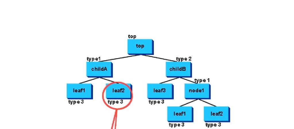
16 We say that a parent instantiates a child module. That is, it creates an instance of it to be a submodel of the parent. In this example, system instantiates comp_1, comp_2 comp_2 instantiates sub_3 Modules in a hierarchy have both a type and a name. Module types are defined in Verilog. There can be many module instances of the same type of module in a single hierarchy. The module definition by itself does not create a module. Modules are created by being instantiated in another module, like this: module <module_name_1> (<portlist>);.. <module_name_2> <instance_name> (<portlist>);.. endmodule
17
Logic Implementation on a Xilinx FPGA using VHDL WWU Linux platform assumed. rev 11/01/17
 1 Logic Implementation on a Xilinx FPGA using VHDL WWU Linux platform assumed. rev 11/01/17 The following is a general outline of steps (i.e. design flow) used to implement a digital system described with
CECS LAB 1 Introduction to Xilinx EDA Tools
 NAME: DUE DATE: STUDENT ID: POSSIBLE POINTS: 10 COURSE DATE & TIME: OBJECTIVE: To familiarize ourselves with the Xilinx Electronic Design Aid (EDA) Tools. We will simulate a simple 4-to-1 Multiplexor using
Xilinx Schematic Entry Tutorial
 Overview Xilinx Schematic Entry Tutorial Xilinx ISE Schematic Entry & Modelsim Simulation What is circuit simulation and why is it important? Complex designs, short design cycle Simultaneous system design
Programming Xilinx SPARTAN 3 Board (Simulation through Implementation)
") Programming Xilinx SPARTAN 3 Board (Simulation through Implementation) September 2008 Prepared by: Oluwayomi Adamo Class: Project IV University of North Texas FPGA Physical Description 4 1. VGA (HD-15)
Programming Xilinx SPARTAN 3 Board (Simulation through Implementation) September 2008 Prepared by: Oluwayomi Adamo Class: Project IV University of North Texas FPGA Physical Description 4 1. VGA (HD-15)
EE 367 Logic Design Lab #1 Introduction to Xilinx ISE and the ML40X Eval Board Date: 1/21/09 Due: 1/28/09
 EE 367 Logic Design Lab #1 Introduction to Xilinx ISE and the ML40X Eval Board Date: 1/21/09 Due: 1/28/09 Lab Description Today s lab will introduce you to the Xilinx Integrated Software Environment (ISE)
TLL5000 Electronic System Design Base Module. Getting Started Guide, Ver 3.4
 TLL5000 Electronic System Design Base Module Getting Started Guide, Ver 3.4 COPYRIGHT NOTICE The Learning Labs, Inc. ( TLL ) All rights reserved, 2008 Reproduction in any form without permission is prohibited.
Actel Libero TM Integrated Design Environment v2.3 Structural Schematic Flow Design Tutorial
 Actel Libero TM Integrated Design Environment v2.3 Structural Schematic Flow Design Tutorial 1 Table of Contents Design Flow in Libero TM IDE v2.3 Step 1 - Design Creation 3 Step 2 - Design Verification
Logic Implementation on a Xilinx FPGA using VHDL WWU Linux platform assumed. rev 10/25/16
 1 Logic Implementation on a Xilinx FPGA using VHDL WWU Linux platform assumed. rev 10/25/16 The following is a general outline of steps (i.e. design flow) used to implement a digital system described with
Building Combinatorial Circuit Using Behavioral Modeling Lab
 Building Combinatorial Circuit Using Behavioral Modeling Lab Overview: In this lab you will learn how to model a combinatorial circuit using behavioral modeling style of Verilog HDL. You will model a combinatorial
Circuit design with configurable devices (FPGA)
") 1 Material Circuit design with configurable devices (FPGA) Computer with Xilinx's ISE software installed. Digilent's Basys2 prototype board and documentation. Sample design files (lab kit). Files and documents
1 Material Circuit design with configurable devices (FPGA) Computer with Xilinx's ISE software installed. Digilent's Basys2 prototype board and documentation. Sample design files (lab kit). Files and documents
Xilinx ISE Synthesis Tutorial
 Xilinx ISE Synthesis Tutorial The following tutorial provides a basic description of how to use Xilinx ISE to create a simple 2-input AND gate and synthesize the design onto the Spartan-3E Starter Board
TLL5000 Electronic System Design Base Module
 TLL5000 Electronic System Design Base Module The Learning Labs, Inc. Copyright 2007 Manual Revision 2007.12.28 1 Copyright 2007 The Learning Labs, Inc. Copyright Notice The Learning Labs, Inc. ( TLL )
Tutorial: Working with Verilog and the Xilinx FPGA in ISE 9.2i
 Tutorial: Working with Verilog and the Xilinx FPGA in ISE 9.2i This tutorial will show you how to: Use Verilog to specify a design Simulate that Verilog design Define pin constraints for the FPGA (.ucf
Revision: February 27, E Main Suite D Pullman, WA (509) Voice and Fax
 Voice and Fax") Xilinx ISE WebPACK Schematic Capture Tutorial Revision: February 27, 2010 215 E Main Suite D Pullman, WA 99163 (509) 334 6306 Voice and Fax Overview This tutorial provides instruction for using the Xilinx
Xilinx ISE WebPACK Schematic Capture Tutorial Revision: February 27, 2010 215 E Main Suite D Pullman, WA 99163 (509) 334 6306 Voice and Fax Overview This tutorial provides instruction for using the Xilinx
EE183 LAB TUTORIAL. Introduction. Projects. Design Entry
 EE183 LAB TUTORIAL Introduction You will be using several CAD tools to implement your designs in EE183. The purpose of this lab tutorial is to introduce you to the tools that you will be using, Xilinx
CPEN 230L: Introduction to Digital Logic Laboratory Lab #6: Verilog and ModelSim
 CPEN 230L: Introduction to Digital Logic Laboratory Lab #6: Verilog and ModelSim Purpose Define logic expressions in Verilog using register transfer level (RTL) and structural models. Use Quartus II to
Using Synplify Pro, ISE and ModelSim
 Using Synplify Pro, ISE and ModelSim VLSI Systems on Chip ET4 351 Rene van Leuken Huib Lincklaen Arriëns Rev. 1.2 The EDA programs that will be used are: For RTL synthesis: Synplicity Synplify Pro For
University of Hawaii EE 361L. Getting Started with Spartan 3E Digilent Basys2 Board. Lab 4.1
 University of Hawaii EE 361L Getting Started with Spartan 3E Digilent Basys2 Board Lab 4.1 I. Test Basys2 Board Attach the Basys2 board to the PC or laptop with the USB connector. Make sure the blue jumper
FPGA Design Tutorial
 ECE 554 Digital Engineering Laboratory FPGA Design Tutorial Version 5.0 Fall 2006 Updated Tutorial: Jake Adriaens Original Tutorial: Matt King, Surin Kittitornkun and Charles R. Kime Table of Contents
Tutorial: Working with the Xilinx tools 14.4
 Tutorial: Working with the Xilinx tools 14.4 This tutorial will show you how to: Part I: Set up a new project in ISE Part II: Implement a function using Schematics Part III: Implement a function using
COS/ELE 375 Verilog & Design Tools Tutorial
 COS/ELE 375 Verilog & Design Tools Tutorial In this tutorial, you will walk through a tutorial using the Xilinx ISE design software with a Digilent Nexys4 DDR FPGA board. In this tutorial, you will learn
Getting Started with Xilinx WebPack 13.1
 Getting Started with Xilinx WebPack 13.1 B. Ackland June 2011 (Adapted from S. Tewksbury notes WebPack 7.1) This tutorial is designed to help you to become familiar with the operation of the WebPack software
UNIVERSITY OF CALIFORNIA, DAVIS Department of Electrical and Computer Engineering. EEC180A DIGITAL SYSTEMS I Winter 2015
 UNIVERSITY OF CALIFORNIA, DAVIS Department of Electrical and Computer Engineering EEC180A DIGITAL SYSTEMS I Winter 2015 LAB 1: Introduction to Quartus II Schematic Capture and ModelSim Simulation This
Xilinx Tutorial Basic Walk-through
 Introduction to Digital Logic Design with FPGA s: Digital logic circuits form the basis of all digital electronic devices. FPGAs (Field Programmable Gate Array) are large programmable digital electronic
Xilinx ISE/WebPack: Introduction to Schematic Capture and Simulation
 Xilinx ISE/WebPack: Introduction to Schematic Capture and Simulation Revision: February 7, 2003 Overview This document is intended to assist new entry-level users of the Xilinx ISE/WebPack software. It
ECE 491 Laboratory 1 Introducing FPGA Design with Verilog September 6, 2004
 Goals ECE 491 Laboratory 1 Introducing FPGA Design with Verilog September 6, 2004 1. To review the use of Verilog for combinational logic design. 2. To become familiar with using the Xilinx ISE software
Step 1: Downloading the source files
 Introduction: In this lab and in the remainder of the ELEC 2607 labs, you will be using the Xilinx ISE to enter and simulate the designs for your circuits. In labs 3 and 4, you will use ISE to compile
Xilinx Project Navigator Reference Guide
 31 July 2003 Author: David M. Sendek Xilinx Project Navigator Reference Guide Background: This guide provides you with step-by-step procedures in using the Xilinx Project Navigator to perform the following:
Revision: February 27, E Main Suite D Pullman, WA (509) Voice and Fax
 Voice and Fax") Xilinx ISE WebPACK VHDL Tutorial Revision: February 27, 2010 215 E Main Suite D Pullman, WA 99163 (509) 334 6306 Voice and Fax Overview This tutorial provides simple instruction for using the Xilinx ISE
Xilinx ISE WebPACK VHDL Tutorial Revision: February 27, 2010 215 E Main Suite D Pullman, WA 99163 (509) 334 6306 Voice and Fax Overview This tutorial provides simple instruction for using the Xilinx ISE
CSE 591: Advanced Hardware Design and Verification (2012 Spring) LAB #0
 LAB #0") Lab 0: Tutorial on Xilinx Project Navigator & ALDEC s Active-HDL Simulator CSE 591: Advanced Hardware Design and Verification Assigned: 01/05/2011 Due: 01/19/2011 Table of Contents 1 Overview... 2 1.1
Lab 0: Tutorial on Xilinx Project Navigator & ALDEC s Active-HDL Simulator CSE 591: Advanced Hardware Design and Verification Assigned: 01/05/2011 Due: 01/19/2011 Table of Contents 1 Overview... 2 1.1
MANUAL XILINX ISE PROJECT NAVIGATOR
 Hochschule für Angewandte Wissenschaften Hamburg University of Applied Sciences Department of Electrical Engineering and Computer Sciences MANUAL XILINX ISE PROJECT NAVIGATOR AND MODELSIM Design Flow for
ECE 4305 Computer Architecture Lab #1
 ECE 4305 Computer Architecture Lab #1 The objective of this lab is for students to familiarize with the FPGA prototyping system board (Nexys-2) and the Xilinx software development environment that will
Quick Front-to-Back Overview Tutorial
 Quick Front-to-Back Overview Tutorial PlanAhead Design Tool This tutorial document was last validated using the following software version: ISE Design Suite 14.5 If using a later software version, there
Laboratory Exercise #6 Introduction to Logic Simulation and Verilog
 Laboratory Exercise #6 Introduction to Logic Simulation and Verilog ECEN 248: Introduction to Digital Design Department of Electrical and Computer Engineering Texas A&M University 2 Laboratory Exercise
Digital Circuit Design Using Xilinx ISE Tools
 Digital Circuit Design Using Xilinx ISE Tools Poras T. Balsara and Prashant Vallur Table of Contents 1. Introduction 2. Programmable logic devices: FPGA and CPLD 3. Creating a new project in Xilinx Foundation
Contents. Appendix B HDL Entry Tutorial 2 Page 1 of 14
 Appendix B HDL Entry Tutorial 2 Page 1 of 14 Contents Appendix B HDL Entry Tutorial 2...2 B.1 Getting Started...2 B.1.1 Preparing a Folder for the Project...2 B.1.2 Starting Quartus II...2 B.1.3 Creating
Laboratory of Digital Circuits Design: Design, Implementation and Simulation of Digital Circuits Using Programmable Devices
 Internet Engineering Dr. Jarosław Sugier Laboratory of Digital Circuits Design: Design, Implementation and Simulation of Digital Circuits Using Programmable Devices This document presents software packages
PlanAhead Release Notes
 PlanAhead Release Notes What s New in the 11.1 Release UG656(v 11.1.0) April 27, 2009 PlanAhead 11.1 Release Notes Page 1 Table of Contents What s New in the PlanAhead 11.1 Release... 4 Device Support...
EECS150 - Digital Design Lecture 10 Logic Synthesis
 EECS150 - Digital Design Lecture 10 Logic Synthesis September 26, 2002 John Wawrzynek Fall 2002 EECS150 Lec10-synthesis Page 1 Logic Synthesis Verilog and VHDL stated out as simulation languages, but quickly
RTL Design and IP Generation Tutorial. PlanAhead Design Tool
 RTL Design and IP Generation Tutorial PlanAhead Design Tool Notice of Disclaimer The information disclosed to you hereunder (the "Materials") is provided solely for the selection and use of Xilinx products.
Speaker: Shao-Wei Feng Adviser: Prof. An-Yeu Wu Date: 2010/09/28
 99-1 Under-Graduate Project Verilog Simulation & Debugging Tools Speaker: Shao-Wei Feng Adviser: Prof. An-Yeu Wu Date: 2010/09/28 ACCESS IC LAB Outline Basic Concept of Verilog HDL Gate Level Modeling
Don t expect to be able to write and debug your code during the lab session.
 EECS150 Spring 2002 Lab 4 Verilog Simulation Mapping UNIVERSITY OF CALIFORNIA AT BERKELEY COLLEGE OF ENGINEERING DEPARTMENT OF ELECTRICAL ENGINEERING AND COMPUTER SCIENCE Lab 4 Verilog Simulation Mapping
EECS150 - Digital Design Lecture 10 Logic Synthesis
 EECS150 - Digital Design Lecture 10 Logic Synthesis February 13, 2003 John Wawrzynek Spring 2003 EECS150 Lec8-synthesis Page 1 Logic Synthesis Verilog and VHDL started out as simulation languages, but
ELEC 204 Digital System Design LABORATORY MANUAL
 ELEC 204 Digital System Design LABORATORY MANUAL : Introductory Tutorial For Xilinx ISE Foundation v10.1 & Implementing XOR Gate College of Engineering Koç University Important Note: In order to effectively
Lab 3 Verilog Simulation Mapping
 University of California at Berkeley College of Engineering Department of Electrical Engineering and Computer Sciences 1. Motivation Lab 3 Verilog Simulation Mapping In this lab you will learn how to use
EMT1250 LABORATORY EXPERIMENT. EXPERIMENT # 6: Quartus II Tutorial and Practice. Name: Date:
 EXPERIMENT # 6: Quartus II Tutorial and Practice Name: Date: Equipment/Parts Needed: Quartus II R Web Edition V9.1 SP2 software by Altera Corporation USB drive to save your files Objective: Learn how to
PlanAhead Software Tutorial
 PlanAhead Software Tutorial RTL Design and IP Generation The information disclosed to you hereunder (the Information ) is provided AS-IS with no warranty of any kind, express or implied. Xilinx does not
TUTORIAL On USING XILINX ISE FOUNDATION DESIGN TOOLS: Mixing VHDL and Schematics
 TUTORIAL On USING XILINX ISE FOUNDATION DESIGN TOOLS: Mixing VHDL and Schematics Shawki Areibi July 7, 2005 1 Introduction The objective of this tutorial is to show how VHDL can be incorporated into a
Xilinx ChipScope ICON/VIO/ILA Tutorial
 Xilinx ChipScope ICON/VIO/ILA Tutorial The Xilinx ChipScope tools package has several modules that you can add to your Verilog design to capture input and output directly from the FPGA hardware. These
EE 1315 DIGITAL LOGIC LAB EE Dept, UMD
 EE 1315 DIGITAL LOGIC LAB EE Dept, UMD EXPERIMENT # 1: Logic building blocks The main objective of this experiment is to let you familiarize with the lab equipment and learn about the operation of the
Lab 1: Introduction to Verilog HDL and the Xilinx ISE
 EE 231-1 - Fall 2016 Lab 1: Introduction to Verilog HDL and the Xilinx ISE Introduction In this lab simple circuits will be designed by programming the field-programmable gate array (FPGA). At the end
Getting started with the Xilinx Project Navigator and the Digilent BASYS 2 board.
 Getting started with the Xilinx Project Navigator and the Digilent BASYS 2 board. This lab is based on: Xilinx Project Navigator, Release Version 14.6 Digilent Adept System Rev 2.7, Runtime Rev 2.16 Digilent
Programmable Logic Design I
 Programmable Logic Design I Introduction In labs 11 and 12 you built simple logic circuits on breadboards using TTL logic circuits on 7400 series chips. This process is simple and easy for small circuits.
CS152 FPGA CAD Tool Flow University of California at Berkeley College of Engineering Department of Electrical Engineering and Computer Sciences
 CS152 FPGA CAD Tool Flow University of California at Berkeley College of Engineering Department of Electrical Engineering and Computer Sciences Compiled: 4/3/2003 for CS152 Spring 03, Prof. John Kubiatowicz
Tutorial: ISE 12.2 and the Spartan3e Board v August 2010
 Tutorial: ISE 12.2 and the Spartan3e Board v12.2.1 August 2010 This tutorial will show you how to: Use a combination of schematics and Verilog to specify a design Simulate that design Define pin constraints
Tutorial on FPGA Design Flow based on Xilinx ISE WebPack and ModelSim. ver. 2.0
 Tutorial on FPGA Design Flow based on Xilinx ISE WebPack and ModelSim ver. 2.0 Updated: Fall 2013 1 Preparing the Input: Download examples associated with this tutorial posted at http://ece.gmu.edu/tutorials-and-lab-manuals
Verilog Simulation Mapping
 1 Motivation UNIVERSITY OF CALIFORNIA AT BERKELEY COLLEGE OF ENGINEERING DEPARTMENT OF ELECTRICAL ENGINEERING AND COMPUTER SCIENCE Lab 4 Verilog Simulation Mapping In this lab you will learn how to use
Department of Electrical and Computer Engineering Xilinx ISIM <Release Version: 14.1i> Simulation Tutorial Using Verilog
 Department of Electrical and Computer Engineering Xilinx ISIM Simulation Tutorial Using Verilog Spring 2013 Baback Izadi You will next test the full adder circuit that you built
structure syntax different levels of abstraction
 This and the next lectures are about Verilog HDL, which, together with another language VHDL, are the most popular hardware languages used in industry. Verilog is only a tool; this course is about digital
Here is a list of lecture objectives. They are provided for you to reflect on what you are supposed to learn, rather than an introduction to this
 This and the next lectures are about Verilog HDL, which, together with another language VHDL, are the most popular hardware languages used in industry. Verilog is only a tool; this course is about digital
DESIGN STRATEGIES & TOOLS UTILIZED
 CHAPTER 7 DESIGN STRATEGIES & TOOLS UTILIZED 7-1. Field Programmable Gate Array The internal architecture of an FPGA consist of several uncommitted logic blocks in which the design is to be encoded. The
1. Downloading. 2. Installation and License Acquiring. Xilinx ISE Webpack + Project Setup Instructions
 Xilinx ISE Webpack + Project Setup Instructions 1. Downloading The Xilinx tools are free for download from their website and can be installed on your Windowsbased PC s. Go to the following URL: http://www.xilinx.com/support/download/index.htm
Vivado Tutorial. Introduction. Objectives. Procedure. Lab Workbook. Vivado Tutorial
 Lab Workbook Introduction This tutorial guides you through the design flow using Xilinx Vivado software to create a simple digital circuit using Verilog HDL. A typical design flow consists of creating
Tutorial on FPGA Design Flow based on Xilinx ISE Webpack and ModelSim. ver. 1.5
 Tutorial on FPGA Design Flow based on Xilinx ISE Webpack and ModelSim ver. 1.5 1 Prepared by Marcin Rogawski, Ekawat (Ice) Homsirikamol, Kishore Kumar Surapathi and Dr. Kris Gaj The example codes used
EET2141 Project 2: Binary Adder Using Xilinx 7.1i Due Friday April 25
 EET2141 Project 2: Binary Adder Using Xilinx 7.1i Due Friday April 25 Introduction This Xilinx project introduces the characteristics of the ripple carry adder. From the last project, you learned that
Hardware Description Languages (HDLs) Verilog
 Verilog") Hardware Description Languages (HDLs) Verilog Material from Mano & Ciletti book By Kurtulus KULLU Ankara University What are HDLs? A Hardware Description Language resembles a programming language specifically
Hardware Description Languages (HDLs) Verilog Material from Mano & Ciletti book By Kurtulus KULLU Ankara University What are HDLs? A Hardware Description Language resembles a programming language specifically
Advanced module: Video en/decoder on Virtex 5
 Advanced module: Video en/decoder on Virtex 5 Content 1. Advanced module: Video en/decoder on Virtex 5... 2 1.1. Introduction to the lab environment... 3 1.1.1. Remote control... 4 1.2. Getting started
Lab 2 Designing with Verilog
 UNIVERSITY OF CALIFORNIA AT BERKELEY COLLEGE OF ENGINEERING DEPARTMENT OF ELECTRICAL ENGINEERING AND COMPUTER SCIENCE Lab 2 Designing with Verilog 1.0 Motivation In this lab you will learn how to express
ECT 224: Digital Computer Fundamentals Using Xilinx StateCAD
 ECT 224: Digital Computer Fundamentals Using Xilinx StateCAD 1) Sequential circuit design often starts with a problem statement tat can be realized in the form of a state diagram or state table a) Xilinx
Quartus II Version 14.0 Tutorial Created September 10, 2014; Last Updated January 9, 2017
 Quartus II Version 14.0 Tutorial Created September 10, 2014; Last Updated January 9, 2017 This tutorial will walk you through the process of developing circuit designs within Quartus II, simulating with
Introduction to WebPACK 4.1 for CPLDs. Using Xilinx WebPACK Software to Create CPLD Designs for the XS95 Board
 Introduction to WebPACK 4.1 for CPLDs Using Xilinx WebPACK Software to Create CPLD Designs for the XS95 Board Release date: 10/29/2001 All XS-prefix product designations are trademarks of XESS Corp. All
Introduction to WebPACK 3.1. Using XILINX WebPACK Software to Create CPLD Designs
 Introduction to WebPACK 3.1 Using XILINX WebPACK Software to Create CPLD Designs RELEASE DATE: 8/28/2000 All XS-prefix product designations are trademarks of XESS Corp. All XC-prefix product designations
VHDL for Synthesis. Course Description. Course Duration. Goals
 VHDL for Synthesis Course Description This course provides all necessary theoretical and practical know how to write an efficient synthesizable HDL code through VHDL standard language. The course goes
Logic Synthesis. EECS150 - Digital Design Lecture 6 - Synthesis
 Logic Synthesis Verilog and VHDL started out as simulation languages, but quickly people wrote programs to automatically convert Verilog code into low-level circuit descriptions (netlists). EECS150 - Digital
EXPERIMENT NUMBER 7 HIERARCHICAL DESIGN OF A FOUR BIT ADDER (EDA-2)
") 7-1 EXPERIMENT NUMBER 7 HIERARCHICAL DESIGN OF A FOUR BIT ADDER (EDA-2) Purpose The purpose of this exercise is to explore more advanced features of schematic based design. In particular you will go through
7-1 EXPERIMENT NUMBER 7 HIERARCHICAL DESIGN OF A FOUR BIT ADDER (EDA-2) Purpose The purpose of this exercise is to explore more advanced features of schematic based design. In particular you will go through
Introduction to WebPACK 5.2 for FPGAs. Using Xilinx WebPACK Software to Create FPGA Designs for the XSB-300E Board
 Introduction to WebPACK 5.2 for FPGAs Using Xilinx WebPACK Software to Create FPGA Designs for the XSB-300E Board Release date: 10/27/2003 All XS-prefix product designations are trademarks of XESS Corp.
Tutorial on Quartus II Introduction Using Verilog Code
 Tutorial on Quartus II Introduction Using Verilog Code (Version 15) 1 Introduction This tutorial presents an introduction to the Quartus II CAD system. It gives a general overview of a typical CAD flow
Quartus II Tutorial. September 10, 2014 Quartus II Version 14.0
 Quartus II Tutorial September 10, 2014 Quartus II Version 14.0 This tutorial will walk you through the process of developing circuit designs within Quartus II, simulating with Modelsim, and downloading
Using XILINX WebPACK Software to Create CPLD Designs
 Introduction to WebPACK Using XILINX WebPACK Software to Create CPLD Designs RELEASE DATE: 10/24/1999 All XS-prefix product designations are trademarks of XESS Corp. All XC-prefix product designations
Lab 6 : Introduction to Verilog
 Lab 6 : Introduction to Verilog Name: Sign the following statement: On my honor, as an Aggie, I have neither given nor received unauthorized aid on this academic work 1 Objective The main objective of
Circuit Design and Simulation with VHDL 2nd edition Volnei A. Pedroni MIT Press, 2010 Book web:
 Circuit Design and Simulation with VHDL 2nd edition Volnei A. Pedroni MIT Press, 2010 Book web: www.vhdl.us Appendix C Xilinx ISE Tutorial (ISE 11.1) This tutorial is based on ISE 11.1 WebPack (free at
MicroBlaze Tutorial on EDK 10.1 using Sparatan III E Behavioural Simulation of MicroBlaze System
 MicroBlaze Tutorial on EDK 10.1 using Sparatan III E Behavioural Simulation of MicroBlaze System Ahmed Elhossini January 24, 2010 1 Introduction 1.1 Objectives This tutorial will demonstrate process of
2IN35 VLSI Programming Lab Work Assignment 1: Hardware design using Verilog
 2IN35 VLSI Programming Lab Work Assignment 1: Hardware design using Verilog Hrishikesh Salunkhe, h.l.salunkhe@tue.nl, Alok Lele, a.lele@tue.nl April 28, 2015 1 Contents 1 Introduction 3 2 Hardware design
Tutorial on FPGA Design Flow based on Xilinx ISE Webpack and ModelSim. ver. 1.3
 Tutorial on FPGA Design Flow based on Xilinx ISE Webpack and ModelSim ver. 1.3 1 Prepared by Marcin Rogawski, Ekawat (Ice) Homsirikamol, Kishorekum Surapathi, and Dr. Kris Gaj The example codes used in
Using ModelSim to Simulate Logic Circuits for Altera FPGA Devices
 Using ModelSim to Simulate Logic Circuits for Altera FPGA Devices This tutorial is a basic introduction to ModelSim, a Mentor Graphics simulation tool for logic circuits. We show how to perform functional
University of California, Davis Department of Electrical and Computer Engineering. Lab 1: Implementing Combinational Logic in the MAX10 FPGA
 1 University of California, Davis Department of Electrical and Computer Engineering EEC180B DIGITAL SYSTEMS II Winter Quarter 2018 Lab 1: Implementing Combinational Logic in the MAX10 FPGA Objective: This
RTL and Technology Schematic Viewers Tutorial. UG685 (v13.1) March 1, 2011
 March 1, 2011") RTL and Technology Schematic Viewers Tutorial The information disclosed to you hereunder (the Information ) is provided AS-IS with no warranty of any kind, express or implied. Xilinx does not assume any
RTL and Technology Schematic Viewers Tutorial The information disclosed to you hereunder (the Information ) is provided AS-IS with no warranty of any kind, express or implied. Xilinx does not assume any
and 32 bit for 32 bit. If you don t pay attention to this, there will be unexpected behavior in the ISE software and thing may not work properly!
 This tutorial will show you how to: Part I: Set up a new project in ISE 14.7 Part II: Implement a function using Schematics Part III: Simulate the schematic circuit using ISim Part IV: Constraint, Synthesize,
4. Verify that HDL is selected as the Top-Level Source Type, and click Next. The New Project Wizard Device Properties page appears.
 Working with the GODIL Author: Ruud Baltissen Credits: Michael Randelzhofer, Ed Spittles Date: August 2010 What is it? This document describes a way to get familiar with the Xilinx FPGAs on OHO s Godil,
FPGA Block Modular Design Tutorial
 FPGA Block Modular Design Tutorial Introduction This tutorial describes the Block Modular Design (BMD) methodology and relative tools in isplever that assist distributed teams in collaborating on large
Chapter 2 Getting Hands on Altera Quartus II Software
 Chapter 2 Getting Hands on Altera Quartus II Software Contents 2.1 Installation of Software... 20 2.2 Setting Up of License... 21 2.3 Creation of First Embedded System Project... 22 2.4 Project Building
Generating Parameterized Modules and IP Cores
 Generating Parameterized Modules and IP Cores Table of Contents...3 Module 1: Verilog HDL Design with LPMs Using the Module/IP Manager...4 Task 1: Create a New Project...5 Task 2: Target a Device...7 Task
ENGN3213. Digital Systems & Microprocessors. CLAB 1: ICARUS Verilog and ISE WebPACK
 Department of Engineering Australian National University ENGN3213 Digital Systems & Microprocessors CLAB 1: ICARUS Verilog and ISE WebPACK V3.0 Copyright 2010 G.G. Borg ANU Engineering 1 Contents 1 CLAB1:
Introduction to WebPACK 6.3. Using Xilinx WebPACK Software to Create FPGA Designs for the XSA Board
 Introduction to WebPACK 6.3 Using Xilinx WebPACK Software to Create FPGA Designs for the XSA Board Release date: 1/1/2005 2005 by XESS Corp. All XS-prefix product designations are trademarks of XESS Corp.
ANADOLU UNIVERSITY DEPARTMENT OF ELECTRICAL AND ELECTRONICS ENGINEERING. EEM Digital Systems II
 ANADOLU UNIVERSITY DEPARTMENT OF ELECTRICAL AND ELECTRONICS ENGINEERING EEM 334 - Digital Systems II LAB 1 - INTRODUCTION TO XILINX ISE SOFTWARE AND FPGA 1. PURPOSE In this lab, after you learn to use
ECEN 449: Microprocessor System Design Department of Electrical and Computer Engineering Texas A&M University. Laboratory Exercise #1 Using the Vivado
 ECEN 449: Microprocessor System Design Department of Electrical and Computer Engineering Texas A&M University Prof. Sunil P Khatri (Lab exercise created and tested by Ramu Endluri, He Zhou, Andrew Douglass
PINE TRAINING ACADEMY
 PINE TRAINING ACADEMY Course Module A d d r e s s D - 5 5 7, G o v i n d p u r a m, G h a z i a b a d, U. P., 2 0 1 0 1 3, I n d i a Digital Logic System Design using Gates/Verilog or VHDL and Implementation
Using ModelSim to Simulate Logic Circuits in VHDL Designs. 1 Introduction. For Quartus II 13.0
 Using ModelSim to Simulate Logic Circuits in VHDL Designs For Quartus II 13.0 1 Introduction This tutorial is a basic introduction to ModelSim, a Mentor Graphics simulation tool for logic circuits. We
ISE Design Suite Software Manuals and Help
 ISE Design Suite Software Manuals and Help These documents support the Xilinx ISE Design Suite. Click a document title on the left to view a document, or click a design step in the following figure to
Tutorial 2 Implementing Circuits in Altera Devices
 Appendix C Tutorial 2 Implementing Circuits in Altera Devices In this tutorial we describe how to use the physical design tools in Quartus II. In addition to the modules used in Tutorial 1, the following