Cinema Pro-K5. Operations Manual
|
|
|
- Evan Waters
- 5 years ago
- Views:
Transcription

1 Cinema Pro-K5 Operations Manual
2 BEFORE YOU START, READ THESE WARNINGS 1) NEVER PLUG POWER DEVICES OTHER THAN THOSE SUPPLIED BY VARIZOOM INTO THE SYSTEM. ONLY USE VARIZOOM POWER SOURCES AND CABLES. USING DIFFERENT POWER COMPONENTS CAN LEAD TO SEVERE DAMAGE TO THE HEAD AND EVEN THE CAMERA. THIS TYPE OF DAMAGE IS NOT COVERED UNDER WARRANTY. 2) DO NOT MODIFY THE SUPPLIED CABLES OR ATTEMPT TO DISASSEMBLE THE HEAD. 3) LENS CONTROL CABLES MUST ONLY BE PLUGGED INTO THE SPECIFIED INPUT JACK ON THE LENS ITSELF NEVER PLUG A 12-PIN CONNECTOR ON A VARIZOOM LENS CONTROL CABLE INTO THE 12PIN JACK ON THE CAMERA BODY. WHEN IN DOUBT, CONSULT VARIZOOM OR YOUR LENS MANUAL. 4) THE ADVANCED CONTROLLER DOES NOT REQUIRE SEPARATE POWER, IT RECEIVES POWER THROUGH THE GREEN-CODED CONTROL CABLE THAT CONNECTS TO THE HEAD. THE AUX POWER JACK ON THE ADVANCED CONTROLLER IS ONLY UTILIZED IN WIRELESS CONFIGURATIONS AND SHOULD ONLY BE CONNECTED TO A VARIZOOM POWER SUPPLY. 5) DO NOT OPERATE THE HEAD WITH AN UNBALANCED LOAD (i.e., with the camera s weight extremely off-center either horizontally or vertically). 6) DO NOT GET THE SYSTEM WET IT IS NOT WATERPROOF. 7) ALWAYS MAKE SURE YOUR LENS AND POWER CABLES HAVE ENOUGH SLACK RUNNING THROUGH THE TILT AXIS TO PREVENT TWISTING AND TEARING OF THE CABLES. 8) MAKE SURE YOUR LENS CLEARS THE BASE OF THE HEAD WHEN TILTING. IF THE LENS DOES NOT CLEAR THE BASE, SET SOFT LIMITS (SECTION 7) TO PREVENT THE LENS FROM STRIKING THE BASE OF THE HEAD WHEN TILTING. 9) WHEN USING THE CP JR s ONBOARD LENS CONTROLS TO CONTROL YOUR CAMERA, ALWAYS POWER THE CAMERA UP LAST. OTHERWISE, THE RECORD START/STOP FEATURE MAY FALL OUT OF SYNC. TO AVOID THIS ISSUE, JUST MAKE SURE TO CONNECT XLR POWER TO THE HEAD BEFORE YOU TURN YOUR CAMERA ON.
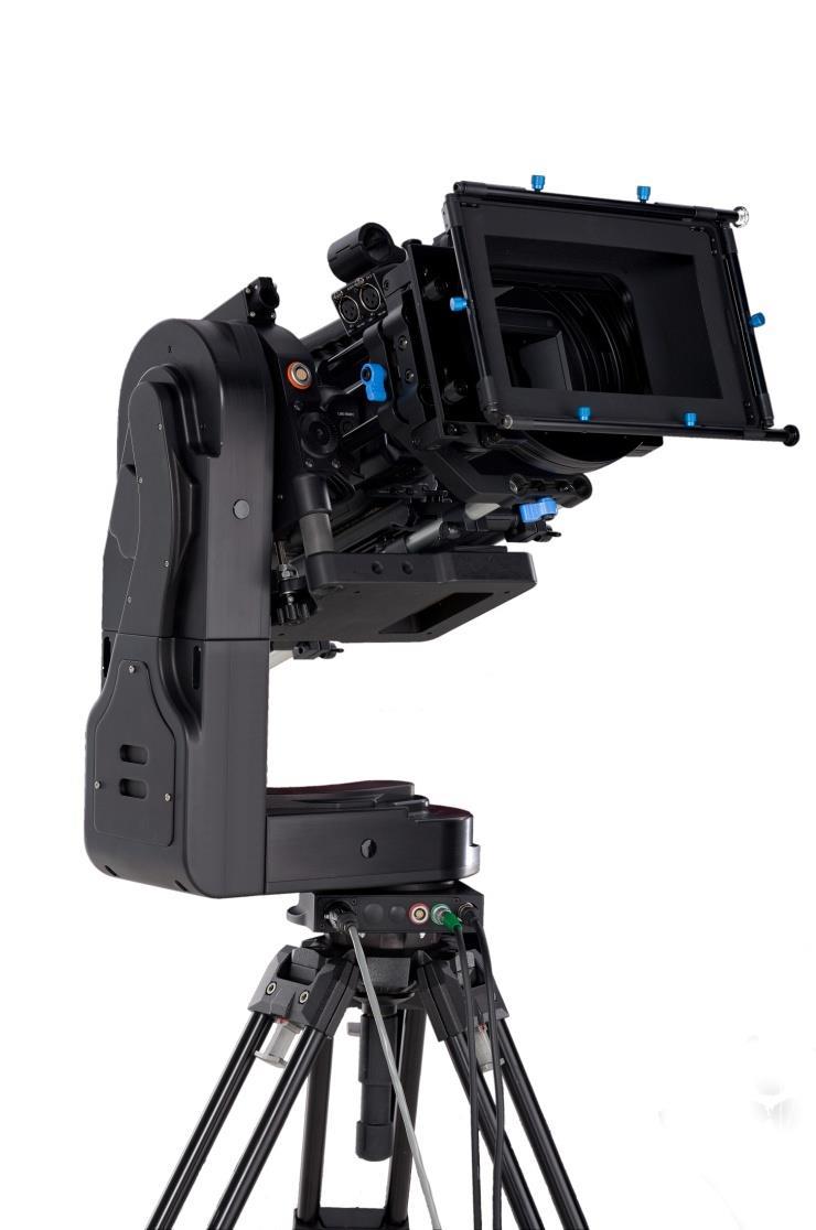
3 General Description The Cinema Pro is a mid-size, two axis motion control head. It has a wide variety of operating modes: manual operation from joystick, optional hand wheels or pan bars control, motion control style record and playback, go to mark preset framing, intervalometer operation and can operate as a slave to Kuper Node motion control*. It also is capable of providing motion data for virtual set operation. The Cinema Pro Advanced Controller gives the user all input and programming capabilities and has a joystick for pan & tilt control. The Advanced Controller also works in concert with two optional control input devices: Pan Bars for broadcast-style operation or Hand Wheels for cinema-style operation. The Jibstick remote is a simpler, less expensive controller designed for oneman jib operation. The jibstick only offers joystick pan & tilt with smoothing and speed control. The Cinema Pro s lens interface controls zoom, focus and iris. It provides four varieties of control signals: RS-232 for Fujinon digital lenses or Varizoom (TOC) motor drives, RS-422 for Canon digital lenses or Preston motor drives, position or speed based analog, pulse width type RC servos, and LANC. The following is an in-depth description of Cinema Pro operation and a complete description of each of its features. *These features are only available when used with the advanced controller.
4 1. Basic Setup Secure Cinema Pro head to crane, tripod, or solid mounting beam Plug the FACTORY POWER SUPPLY into AC mains Connect XLR cable between the Cinema Pro head and FACTORY POWER SUPPLY Connect in Green LEMO connector between the Cinema Pro head and the plug marked CTRL on the controller Connect camera control (if applicable) between the camera and the 12-pin LEMO connector on the back of the tilt arm on Cinema Pro head. Connect camera power (if applicable) between the 2-pin LEMO connector also located on the back of the tilt arm Connect the bloop/sync (if applicable) between the camera and the 6-pin Fischer connector also located on the back of the tilt arm If using the TOC system Connect the TOC 3A (3 axis lens drive box) between the orange 16-PIN lens control connector located on the front of the tilt arm of the Cinema Pro head, and the grey control port located on the TOC 3A Connect the Lens drive motors to the appropriate connection according to their function (zoom, focus, iris)

5 Balance the Camera Although the head will hold position very well, it operates best when the camera is balanced on the mounting platform. With heavier cameras, it is essential, as an out-of-balance load will cause the servos to constantly fight to hold position. Make sure that the motor power is turned off before balancing. This will allow you to move the tilt axis by hand. To balance the camera horizontally, you need to place the camera s front-to-back center of mass at the center of the mounting platform slot. You can do this by trial and error, sliding the camera front-to-back on the mounting platform until it stays level. The simplest accurate way to find the camera s center of mass is to lay a pencil/pen on a table and try to balance the camera on it front-to-back. The spot on the camera where it comes closest to balancing on the pencil is the center of mass. Place the camera s center of mass at the center of the mounting slot and secure the camera with mounting screws (2 if possible). When horizontally balanced, the platform should stay level. Center of Mass With smaller cameras (under 10lbs), you may not need to adjust the vertical balance. For larger cameras, you may want to adjust it for optimal performance and to minimize the effort the servos have to make to hold position. To get the vertical balance right, raise or lower the platform to get the camera s vertical center of mass located on the center of tilt rotation. To adjust, you will have to loosen the lockdown screws (2) on each of the camera platform tubes. Once they are loose, turn the fluted knob on the underside of the platform (between the tubes) to precisely raise or lower it. Rotate the platform to various angles and adjust until it holds position at any angle. If it falls down, you need to adjust the platform upward. If it drifts upward, you need to lower the platform. Note that if you can t get the vertical balance just right, the head will compensate when the servos are powered up. When balance is achieved, tighten the lockdown screws on the platform tubes. After all connections have been made and the camera is balanced, switch on power located on the power brick. After sync is established (the sync light on the jibstick should be illuminated), switch on motor power (See below for location)
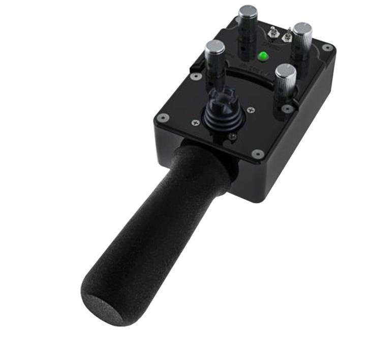
6 2. Jibstick layout and functions Communication Connector Smoothing Pan Speed Pan direction Tilt direction Tilt Speed Pan/Tilt Control joystick Joystick deadband Communication connector (Green)- Connect this to the communication cable, and connect the other end of the communication cable to the green connector on the CinemaPro Head. This cable runs communication as well as power, so make sure that there is XLR power connected to the CinemaPro Pan direction and Tilt direction- Reverses the response direction for each axis
7 Joystick for pan and tilt operation- Move the joystick in the direction you wish the head to move. The response direction can be changed with the response direction switches. Smoothing- Adjusts the amount of smoothing for both the pan and tilt axes. The higher the smoothing is set the more delay there will be in response to the joystick. Pan speed and Tilt Speed- Adjusts the maximum speed for the pan motor and tilt motor. Deadband- Adjusts the amount the joystick must be moved before pan and tilt will respond. 3. Troubleshooting No Response from head 1) Make sure that the motor power switch is turned on, and the light above it is green. 2) Check to make sure that there aren t any soft limits set too close together. Disable all soft limits, and then try again. 3) Power down the system, unplug the XLR connector, wait for a few seconds, re-plug everything back in, power it back up, then try again. Pan and Tilt moves too slowly or PanBar range is limited 1) Check both speed settings. If the speed is dialed too slowly it will appear to have no response at all. Head is jerky or too responsive 1) Turn down motor speed. 5) If you have been using the advanced controller, check to make sure that the servo tuning in the tuning menu is set to the factory setting. Selecting reset all will return this to the factory preset. Note: When the jibstick is plugged into the head, it will default to the servo tuning of the last advanced controller that used with the head. Head moves on its own Cycle power and do not touch the joystick when powering up the system. The joystick has to calibrate on power-up, so if it s off-center then it will calibrate incorrectly.
8 4. Options and Specs Additional Software- The Cinema Pro head can operate as a slave to Kuper Node motion control software, and is also is capable of providing motion data for virtual set operation. Data capture software is available, for data sharing. This will allow you to export the data from the Cinema Pro to a personal computer. Additional Head options- The Cinema Pro head can be fitted with either a 100mm half ball, or Mitchell mount. A Mitchell ring adapter is available for old style Mitchell mount. An adapter is also available to adapt Mitchell mount to Jimmy Jib style mount. Wireless control is available, and can controlled from up to ¼ mile. Up to 1 mile line of sight. Additional controller cables are available in 50 or 100 increments. A male to female LEMO coupler is available to join the cables. Cinema Pro XLR power cables are available in 30 or 75 increments. 2 head extension blocks are available, and will increase the underslung clearance range from to A maximum of two can be installed. This will also increase clearance if using a larger lens. ¼ or 1/8 nodal line offsets can be installed on the Cinema Pro s camera mounting plate to line of the center of the lens when necessary. Dedicated video sliprings can be fitted on the Cinema Pro head to allow high quality SD video to pass through the head. There is a 2db signal loss through this dedicated slip ring, so HD SDI is not supported
9 unless a line driver is introduced. This option will only support HD for monitoring purposes the signal will not be of broadcast quality. HD hardwiring is available for a broadcast-quality HD video signal. (This cable will bypass the slipring, and limit pan and tilt movements to 720 ) Specs- Head construction: Primarily Aluminum, with carbon fiber platform rails and some stainless steel, steel, brass, bronze components Height: 19.5 Width: 12 Depth: 6 Weight: 21 lbs. Maximum speed: 210 deg/sec (max up to 512 deg/sec with custom high speed motors) Underslung Camera Clearance for Standard Head = (camera platform adjusts 2 up/down) Underslung Camera Clearance w/ Head Extensions: w/ 1 extension = ; w/ 2 Extensions = Mechanical travel: unlimited unless hardwired.


 Controller- 7pin LEMO (green) Video out- BNC Tilt arm connector, front Lens")
10 Camera Plate dimensions- From Center mounting hole- tilt arm: 5 (with standard nodal line plate installed. This may be offset by ¼ or 1/8 with offset nodal line plates installed) Camera plate has 2 of vertical adjustment for camera balancing. Connectors- Cinema Pro Base connectors Head power- 4pin XLR Kuper Node- 6pin LEMO (red) Controller- 7pin LEMO (green) Video out- BNC Tilt arm connector, front Lens control- 16pin LEMO (orange) Tilt arm connectors, back Video in- BNC Bloop/sync (optional)- 6pin Fischer
11 Camera control (optional)- 12pin LEMO (white) Camera Power- 2pin LEMO (red) Advanced Controller connectors (not pictured) CTRL - 7Pin LEMO Head control cable (green) SERIAL - 8pin LEMO TOC or Preston Lens Drive Hand Units (gray) ANALOG - 5pin LEMO Pan Bars zoom & focus controls (white) WHEELS - 6pin LEMO Handwheels or Pan Bars Control Input (blue) BLOOP - 6pin Fischer VIDEO SYNC BNC connector Power Supply Connectors Appendix 1) Power Connector XLR4F Pin Function Wire Color 1 Camera Neg. Black 2 Cinema Pro Neg. White 3 Cinema Pro Pos. Red 4 Camera Pos. Green 2) Camera Power Connector Pin Function Destination 1 Camera Neg. Loop to Power Connector 2 N.C. 3 N.C. 4 Camera Pos. Loop to Power Connector *** WARNING: DO NOT POWER THE CINEMAPRO WITH ANYTHING OTHER THAN THE INCLUDED FACTORY POWER SUPPLY OR YOUR WARRANTY MAY BE VOIDED. THE UNIT MAY BE SEVERELY DAMAGED AND CAUSE DAMAGE TO YOUR CAMERA IF YOU USE A NON-APPROVED POWER SUPPLY. IF YOU MUST POWER IT USING A BATTERY
12 SYSTEM, MAKE SURE THE SETUP IS APPROVED BY VARIZOOM AND EXECUTED BY A QUALIFIED TECHNICIAN. Cinema Pro Head - Base Connectors 1) Control Connector (green) LEMO EGG1B307CLL Pin Function Wire Color (Cable) 1 Common Brown 2 RS-422 TXD Red 3 RS-422 TXD! Orange 4 RS-422 RXD Yellow 5 RS-422 RXD! Green 6 24 VDC + Blue Power to Remote or Jibstick 7 24 VDC - Violet Power to Remote or Jibstick 2) Kuper Node Connector (red) LEMO EGG1B306CLL Pin Function DB9 1 Common 1 2 N.C. 3 RS-422 RXD (Kuper) 8 4 RS-422 RXD! (Kuper) 9 5 RS-422 TXD (Kuper) 5 6 RS-422 TXD! (Kuper) 6 3) * Optional - Camera Control Input Connector EGG2B310CLL Pin Function 1 Common 2 12 VDC out 3 Run Switch 4 Remote Enl 5 Remote Clock 6 Remote Direction 7 Clock out 8 Sync out 9 N.C. 10 N.C.
13 4) * Optional - Peripheral Connector EGG1B308CLL Pin Function 1 Common 2 #1 RS-232 RXD 3 #1 RS-232 TXD 4 +5 VDC 5 24 VDC - 6 #2 RS-232 RXD 7 #2 RS-232 TXD 8 24 VDC + Cinema Pro Head Tilt Arm Connectors 1) Camera Power (red) LEMO EGG2B302CLL Pin Function 1 Camera Power + 2 Camera Power - 2) Sync & Bloop Fischer D103A Pin Function 1 Common Iso 2 +5 VDC Iso 3 Sync In 5 Bloop Out #1 6 Bloop Out #2 2) Camera Control (white) LEMO EGG2B312CLL Pin Function 1 Common 2 Enable
14 3 Run push/pull 12 volts 4 Camera run relay Pin1 5 Run pulse 5 VDC 6 Clock out 5 VDC 7 Clock out 12 VDC 8 Clock return 9 RS-232 TXD 10 RS-232 RXD 11 Camera run relay pin2 12 3) Lens Control (orange) Tilt Board Version #2 LEMO EGG2B316CLL (Final Version) Pin Function Lens Connection 1 RS-232 RXD Fuji Digital 2 RS-232 TXD Fuji Digital 3 +5 VDC Iso Fuji Digital 4 Common Iso Fuji Digital 5 RS-422 RXD Canon Digital 6 RS-422 RXD! Canon Digital 7 RS-422 TXD Canon Digital 8 RS-422 TXD! Canon Digital 9 Common VDC 11 Analog #1 Focus 12 Analog #2 Zoom 13 RC Servo #1 Focus 14 RC Servo #2 Zoom VDC VDC
15 Lens Connection Table Lens Control, 16 pin LEMO FGG2B316CLAD Fujinon Digital Fujinon Analog Fujinon Telecon Canon Digital Canon Analog HR10A-10P-10P HR10A-10P-12P HR10A-10J-12P HR25-9P-20P HR25-9P-20P 1 Camera Run Relay 3 2 Camera Run Relay 2 3 Iso Vcc 4 4 IsoCom & IsoCom & 20 - Green 5 RS-422 RXD 17 - Orange 6 RS-422 RXD! 18 - Yellow 7 RS-422 TXD 15 - Brown 8 RS-422 TXD! 16 - Red 9 Common Vcc (5 volts) 11 Analog #1 out 7 (If zoom) 9 (Zoom) 2 12 Analog #2 out 7 (If focus) 8 (focus) 3 13 RC Servo Out 1 14 RC Servo Out 2 15 Head power + out 16 Head power out Tie pins 1 & 2 to 7 for position control Advanced Controller Connectors (console connectors)
16 1) Auxiliary power input 1 Center 18 to 36 volts input 2 Common 2) CTRL - Cinema Pro Control (green) LEMO EGG1B307CLL Pin Function Wire Color (Cable) 1 Common Brown 2 RS-422 RXD Red 3 RS-422 RXD! Orange 4 RS-422 TXD Yellow 5 RS-422 TXD! Green 6 24 VDC + Blue Power from Cinema Pro 7 24 VDC - Violet Power from Cinema Pro 2) SERIAL - Peripheral Connector (gray) EGG1B308CLL Pin Function 1 Common 2 #1 RS-232 RXD 3 #1 RS-232 TXD 4 +5 VDC 5 24 VDC - 6 #2 RS-232 RXD 7 #2 RS-232 TXD 8 24 VDC + 3) ANALOG - Panbars Option Zoom and Focus Control Input (white) EGG1B305CLL 1 Common 2 Motor disable 3 Zoom analog signal 4 Focus analog signal 5 +5 VDC 4) WHEELS - Wheels and Panbars Option Control Input (blue) EGG1B306CLL
17 1 Common 2 +5 VDC 3 Pan encoder signal A 4 Pan encoder signal B 5 Tilt encoder signal A 6 Tilt encoder signal B 5) BLOOP - Sync & Bloop Fischer D103A Common Isolated 2 +5 VDC Isolated 3 Sync In 5 Bloop out #1 7 Bloop out #2 6) VIDEO SYNC - BNC 1 BNC signal 2 Isolated common Jibstick Connectors 1) Cinema Pro Control (Green) LEMO EGG1B307CLL Pin Function Wire Color (Cable) 1 Common Brown 2 RS-422 RXD Red 3 RS-422 RXD! Orange 4 RS-422 TXD Yellow 5 RS-422 TXD! Green 6 24 VDC + Blue Power from Cinema Pro 7 24 VDC - Violet Power from Cinema Pro 2) Focus Input Fischer D103A Common 2 +5 VDC 3 Focus analog signal 4 Zoom analog signal (unused) 5 Common
Cinema Pro JR-K5. Operations Manual
 Cinema Pro JR-K5 Operations Manual BEFORE YOU START, READ THESE WARNINGS 1) NEVER PLUG POWER DEVICES OTHER THAN THOSE SUPPLIED BY VARIZOOM INTO THE SYSTEM. ONLY USE VARIZOOM POWER SOURCES AND CABLES. USING
Cinema Pro Operations Manual
 Cinema Pro Operations Manual - 0 - BEFORE YOU START, READ THESE WARNINGS 1) NEVER PLUG POWER DEVICES OTHER THAN THOSE SUPPLIED BY VARIZOOM INTO THE SYSTEM. ONLY USE VARIZOOM POWER SOURCES AND CABLES. USING
Cinema Pro JR Operations Manual
 Cinema Pro JR Operations Manual - 1 - BEFORE YOU START, READ THESE WARNINGS 1) NEVER PLUG POWER DEVICES OTHER THAN THOSE SUPPLIED BY VARIZOOM INTO THE SYSTEM. ONLY USE VARIZOOM POWER SOURCES AND CABLES.
SCORPIO 30 User s manual
 SCORPIO 30 User s manual 1 INDEX 1-. Description 3 2-. The Electronic Control Box.....5 2-.1 Functions....11 2.1.1 Start up Prodecure.....11 2.1.2 Settings Settings...15 2.1.3 Límits Limits....23 2.1.4
TOC F1 Operations Manual
 TOC F1 Operations Manual - 1 - General Description The TOC F1 is a single channel wireless lens control system. The system can be used on most broadcast or cinema lenses. The TOC F1 includes a hand held
DATASHEET STYPE KIT - TRACKING SYSTEM FOR CAMERA CRANES A SYSTEM FOR HIGH-END VIRTUAL AND AUGMENTED REALITY BROADCAST
 WWW.STYPEGRIP.COM DATASHEET STYPE KIT - TRACKING SYSTEM FOR CAMERA CRANES A SYSTEM FOR HIGH-END VIRTUAL AND AUGMENTED REALITY BROADCAST PAGE 2 STYPE KIT OVERVIEW Stype Kit is a mechanical tracking system
MANUAL. Set-up and Operations Guide Glidecam Industries, Inc. 23 Joseph Street, Kingston, MA Customer Service Line
 MANUAL Set-up and Operations Guide Glidecam Industries, Inc. 23 Joseph Street, Kingston, MA 02364 Customer Service Line 1-781-585-7900 Manufactured in the U.S.A. COPYRIGHT 2015 GLIDECAM INDUSTRIES,Inc.
Boxer HD-2X Motorized Pan Tilt Head (P-BXR-HD-2X)
") Boxer HD-2X Motorized Pan Tilt Head (P-BXR-HD-2X) I N STR UC TI ON MANUAL All rights reserved No part of this document may be reproduced, stored in a retrieval system, or transmitted by any form or by
Boxer HD-2X Motorized Pan Tilt Head (P-BXR-HD-2X) I N STR UC TI ON MANUAL All rights reserved No part of this document may be reproduced, stored in a retrieval system, or transmitted by any form or by
Instruction Manual. Gold Pan Tilt Head with 12V Joystick Control Box (PT-GOLD)
") Instruction Manual Gold Pan Tilt Head with 12V Joystick Control Box (PT-GOLD) All rights reserved No part of this document may be reproduced, stored in a retrieval system, or transmitted by any form or
Instruction Manual Gold Pan Tilt Head with 12V Joystick Control Box (PT-GOLD) All rights reserved No part of this document may be reproduced, stored in a retrieval system, or transmitted by any form or
Jr. Pan Tilt Head (PT-JR) Instruction Manual
 Instruction Manual") 1 Jr. Pan Tilt Head (PT-JR) Instruction Manual 2 At Proaim, our goal is to ensure 100% Customer Satisfaction in all that we do. We back our sales with a 1 year warranty from the date of purchase and work
1 Jr. Pan Tilt Head (PT-JR) Instruction Manual 2 At Proaim, our goal is to ensure 100% Customer Satisfaction in all that we do. We back our sales with a 1 year warranty from the date of purchase and work
TOC DX1-K Operations Manual
 TOC DX1-K Operations Manual - 1 - General Description The TOC DX1-K is a single channel wireless lens control system. The system can be used on most broadcast or cinema lenses. The TOC DX1-K includes a
Pan/Tilt Head with 4K UHD support, IP control, full-carbon body and high loading capability
 Pan/Tilt Head with 4K UHD support, IP control, full-carbon body and high loading capability Featuring a state of the art carbon fiber design, rich connectivity with SDI, Fiber and Ethernet and of course
PEE-POD 500 (FOR SOFTWARE VERSIONS OR LATER) USER'S GUIDE. The PEE POD 500 is a sophisticated tool and extreme care must be taken in its use.
 USER'S GUIDE. The PEE POD 500 is a sophisticated tool and extreme care must be taken in its use.") ref.500userguide.9 PEE-POD 500 (FOR SOFTWARE VERSIONS 2.32.3 OR LATER) USER'S GUIDE IMPORTANT!! The PEE POD 500 is a sophisticated tool and extreme care must be taken in its use. Before the equipment is
ref.500userguide.9 PEE-POD 500 (FOR SOFTWARE VERSIONS 2.32.3 OR LATER) USER'S GUIDE IMPORTANT!! The PEE POD 500 is a sophisticated tool and extreme care must be taken in its use. Before the equipment is
9ft Jib Arm with Tripod (P-9-TS)
") 9ft Jib Arm with Tripod (P-9-TS) I NSTRUC TI ON MANUA L All rights reserved. No part of this document may be reproduced, stored in a retrieval system, or transmitted by any form or by any means, electronic,
9ft Jib Arm with Tripod (P-9-TS) I NSTRUC TI ON MANUA L All rights reserved. No part of this document may be reproduced, stored in a retrieval system, or transmitted by any form or by any means, electronic,
GH-50. Gimbal Head. You re on steady ground
 GH-50 Gimbal Head You re on steady ground 1 INTRODUCTION Thank You for choosing Oben! The Oben GH-50 is a gimbal-type tripod head designed to balance a lens along its vertical and horizontal axes. Ideal
DUTCH LITE. April 03. If you are missing any of the following items, please contact Stanton Video immediately (602)
") DUTCH LITE April 0 If you are missing any of the following items, please contact Stanton Video immediately (602) 49-9505 1. Dutch Axis Assembly 1. Dutch Lite Motor Assembly 1. Motor Controller MAXIMUM
DUTCH LITE April 0 If you are missing any of the following items, please contact Stanton Video immediately (602) 49-9505 1. Dutch Axis Assembly 1. Dutch Lite Motor Assembly 1. Motor Controller MAXIMUM
Micro Force V+F3 ver. 1.1
 Micro Force V+F3 ver. 1.1 Preston Cinema Systems 1659 Eleventh Street Santa Monica, CA 90404 fig 1. V+F3 Controls LEMO receptacle Threaded well for bracket Camera Run Switch Zap Switch Zoom Sensitivity
P/N Operation & Installation Manual Teleprompter Pan/Tilt Head Model PT-LP
 P/N 92 53785 000-11 Operation & Installation Manual Teleprompter Pan/Tilt Head Model PT-LP 92 53785 000 Table of Contents 1.0 Scope...2 2.0 Introduction...2 3.0 Specifications...3 4.0 Installation...4
RONIN 2 Diagram. 1. Grip 2. Gimbal Connector 3. HD-SDI Output 4. Power Button V Accessory Power Port
 RONIN 2 Diagram 1. Grip 2. Gimbal Connector 3. HD-SDI Output 4. Power Button 5. 14.4V Accessory Power Port 6. Pan Motor 7. Camera Upper Mounting Plate 8. GPS 9. HD-SDI Input 10. Focus Mounting Plate 11.
25 Sport Scope Instruction Manual
 25 Sport Scope Instruction Manual Dear Customer, We appreciate your business and value your support for our product. At Sport Scope, we strive to provide our customers with quality, easy to use, and affordable
MINI-HEAD. If any of the following items are missing please contact Stanton Video at (602)
") RATE ZOOM CENTER ZOOM DIRECTION GAIN TALLY LITE TRAVEL DIRECTION STANTON LENS CENTERING DIRECTION MINI-HEAD TRIANGLE HEAD CENTERING DIRECTION MINI-HEAD Sept 99 If any of the following items are missing
RATE ZOOM CENTER ZOOM DIRECTION GAIN TALLY LITE TRAVEL DIRECTION STANTON LENS CENTERING DIRECTION MINI-HEAD TRIANGLE HEAD CENTERING DIRECTION MINI-HEAD Sept 99 If any of the following items are missing
AVT Model Tripod.
 AVT Model Tripod www.ravelliphoto.com Product Overview: The Ravelli AVT professional tripod is a high performance, fluid drag tripod that provides smooth continuous drag control and operates on both pan
STEP 1: MODULE MOUNTING / WIRING:
 VER1.0 PINOUT DIAGRAM: PORT 1 - INPUT 1 (S.BUS, PWM, PPM INPUT) PORT 2 - INPUT 2 (PWM MODE INPUT OR AUX OUTPUT DEFINED IN SOFTWARE) PORT 3 - OUTPUT 1 (S.BUS OUTPUT) PORT 4 - OUTPUT 2 (SERVO OUTPUT) PORT
Focus Command Hand UNIT MANUAL
 1. DESCRIPTION OF THE FRONT PANEL To change the unit of measure (feets/meters). PCMCIA board for radio Focus Motor Control Zoom Motor Control Focus-Iris-Zoom selection Iris Motor Control To change the
Operation & Installation Manual Serial Receiver Driver Model CP-SRD
 92 53600 000-11 Operation & Installation Manual Serial Receiver Driver Model CP-SRD 92 53600 000 Table of Contents 1.0 Scope...1 2.0 Introduction...1 3.0 Specifications...1 4.0 Control Commands...2 5.0
HP Servo Pan/Tilt Head Model PT-HP-S4
 HP Servo Pan/Tilt Head Model PT-HP-S4 User s Manual rev 05/15 www.telemetricsinc.com Revision History Manual Software Version Firmware Version Description May 2015 XXXX XXXX Initial issue. Copyright Copyright
VZ-SnapCrane-16 Professional Modular Camera Crane Instruction Manuall
 VZ-SnapCrane-16 Professional Modular Camera Crane Instruction Manuall WEIGHTS NOT INCLUDED STANDARD 1 -HOLE BARBELL WEIGHTS ARE AVAILABLE AT MOST SPORTING GOODS STORES For a video tutorial SnapCrane Build,
Trusted by thousands of brands globally.
 VariZoom has been a leading manufacturer in film and production tools for over two decades. Based and made in the USA is at the core of our committment to quality. From our full line of Lens Controls to
FILM & VIDEO SETUP MANUAL
 FILM & VIDEO SETUP MANUAL Tyler Nose Mount II for Film or Video cameras. PLEASE RETURN THIS MANUAL WITH EQUIPMENT This manual is available for download from our web site. Tyler Camera Systems 14218 Aetna
TG VR Gimbal User Manual V Accsoon. All Rights Reserved.
 TG20 360 VR Gimbal User Manual V1.0 20161209 www.accsoon.com E-mail: salse@accsoon.com 0 Disclaimers and Warnings Congratulations on purchasing you new VR Gimbal. Please read this manual and disclaimer
JIB EPT USER MANUAL. Please read this manual carefully before using the Alphatron JIB ETP unit! JIB & MOTORISED PAN AND TILT UNIT
 JIB EPT JIB & MOTORISED PAN AND TILT UNIT USER MANUAL EN Please read this manual carefully before using the Alphatron JIB ETP unit! Thank you for purchasing a Alphatron product The EPT head is developed
Proteân XMi. Configurable Remote Head
 Configurable Remote Head Proteân XMi Compact version Width & Height Extension options RS485 with Fibre & IP options Loads >10kg (with 2 nd side) Multiple Head Control from 1 controller Integrated Motion
HuddleCamHD Serial Joystick Controller Model Number: HC-JOY-G3
 HuddleCamHD Serial Joystick Controller Model Number: HC-JOY-G3 Joystick Keyboard Installation & Operation Manual Easy pan, tilt & zoom controls for any RS-232, RS485, RS422 VISCA, Pelco-P or Pelco-D protocol
A Axis M-Functions Level 1 A Axis Standard A Axis SMT Level 2. Each console includes the following:
 Hardware List The 3000M Crusader II Upgrade system has been custom configured to provide the necessary hardware required for installation on your machine. Verify that you have received all the correct
DOWNLOADING THE APP FOR APPLE PHONES: DOWNLOADING THE APP FOR ANDROID PHONES: For Android Phones go to Google Play or the Android Store.
 DOWNLOADING THE APP FOR APPLE PHONES: DOWNLOADING THE APP FOR ANDROID PHONES: For Android Phones go to Google Play or the Android Store. For Apple Phones go to the app store and click GET. Make sure your
MO-SYS L 40-3rd Axis Quick Set-up Guide
 MO-SYS L 40-3rd Axis Quick Set-up Guide WILLIAM F. WHITE INTERNATIONAL INC. Manual Version 1.0 Questions or concerns, please contact Michael Darby 416.707.1549, mdarby@gmail.com MO-SYS L 40 3rd Axis Intro
Digital Camera Controller
 SHUTTERBUG PRO Digital Camera Controller ShutterBug Pro is a tiny accessory that helps take digital or film camera snapshots. It is ideal for photographers that need to remotely snap photos or to time
Nearus USB2.0 Camera Manual NU-350-USB2PTZ-B
 Nearus USB2.0 Camera Manual NU-350-USB2PTZ-B Safety Tips Please read this manual carefully before installing the camera. Keep the camera away from violent vibration, physical stress, moisture, extreme
Zero Gravity Rig Operating Instructions
 Welcome to our new top-of-the-line shoulder support system for cameras up to 15 lbs - the ZG Rig. In addition to its totally unique vertical balancing mechanism, this system is designed to be configurable
PROAIM KITE-22 POPULAR PACKAGE 2 NOTE :
 PROAIM KITE-22 POPULAR PACKAGE 2 IT IS IMPORTANT THAT YOU READ AND UNDERSTAND THIS GUIDE BEFORE ATTEMPTING TO ASSEMBLE OR USE YOUR PROAIM KITE-22 POPULAR PACKAGE. SHOULD YOU NEED ADDITIONAL INFORMATION,
Operators Guide. Vision 3 Pan & Tilt Head. Vinten Camera Control Solutions
 Operators Guide Vision 3 Pan & Tilt Head Vinten Camera Control Solutions Vision 3 Pan and Tilt Head Publication Part No. 3543-8 Issue 4 Copyright Vinten Broadcast Limited 2004 All rights reserved throughout
Warning Before Installation
 Warning Before Installation English Power off the Network Camera as soon as smoke or unusual odors are detected. Refer to your user's manual for the operating temperature. Contact your distributor in the
MegaTrak MCU-9000 Harness Wiring
 MegaTrak MCU-9000 Harness Wiring Contents: 1. MCU9000 Connector Pin-Out Schematic 2. MCU9000 Connections when replacing an MCU3000 3. MCU9000 Connections Using 120VAC ( Hot ) Hook Switch (RS485 cable)
X-CAM A10-3H 3 Axis Gimbal for GOPRO. User Manual ( V2.00 )
") X-CAM A10-3H 3 Axis Gimbal for GOPRO User Manual ( V2.00 ) The X-CAM A10-3H 3 Axis Gimbal has been setup and calibrated for use with GOPRO cameras, it is ready to use straight from the box. Specifications:
X-CAM A10-3H 3 Axis Gimbal for GOPRO User Manual ( V2.00 ) The X-CAM A10-3H 3 Axis Gimbal has been setup and calibrated for use with GOPRO cameras, it is ready to use straight from the box. Specifications:
VZ-SnapCrane-12 Professional Modular Camera Crane Instruction Manuall
 VZ-SnapCrane-12 Professional Modular Camera Crane Instruction Manuall WEIGHTS NOT INCLUDED STANDARD 1 -HOLE BARBELL WEIGHTS ARE AVAILABLE AT MOST SPORTING GOODS STORES For a video tutorial SnapCrane Build,
The Discrete DAC. User Guide. Check our website for the most recent user guides, firmware, and drivers:
 The Discrete DAC User Guide Check our website for the most recent user guides, firmware, and drivers: www.msbtechnology.com Technical support email is: techsupport@msbtech.com 05.21.18 Technical specifications
Ultra light 5-axis camera stabilisation system for professional filming. Dynamic Perspective GmbH Wehlistrasse 29/1/ Vienna, Austria
 Dynamic Perspective GmbH Wehlistrasse 29/1/1 1200 Vienna, Austria http://dynamicperspective.com/dynax5/ sales@dynamicperspective.com +43 (1) 28 100 28-0 Ultra light 5-axis camera stabilisation system for
&%=579 OPERATING INSTRUCTIONS
 &%=579 OPERATING INSTRUCTIONS INDEX INDEX...1 INTRODUCTION...2 Packing contents... 2 Contents of this Instruction Manual... 2 Addressee of the Instruction Manual... 2 What to read... 2 Typographic conventions...
Introduction. Features and Highlights
 Introduction The Nodal Ninja Ultimate M2 Giga (M2G) manual pano head is an ideal solution for capturing high resolution Gigapixel or mosaic type imagery. The M2G will accommodate telephoto lenses up to
GH-30. Gimbal Head. You re on steady ground
 GH-30 Gimbal Head You re on steady ground 1 INTRODUCTION Thank You for choosing Oben! The Oben GH-30 is a gimbal-type tripod head designed to balance a lens along its vertical and horizontal axes. The
PTZ Optics Affordable HDMI, HD-SDI, IP and USB video conferencing cameras
 PTZ Optics Affordable HDMI, HD-SDI, IP and USB video conferencing cameras as 12X SDI (GEN2) Model Number: PT12X-SDI-GY-G2 (gray) PT12X-SDI-WH-G2 (white) http://ptzoptics.com/12x-sdi/ PTZ OPTICS Video
3-Axis Stabilized Handheld Gimbal for Camera. Instructions. Guilin Feiyu Technology Incorporated Company
 3-Axis Stabilized Handheld Gimbal for Camera Instructions Guilin Feiyu Technology Incorporated Company User Manual E N V. 0 Catalogue. G6 Plus Overview 2. Quick Start Guide 3 3. Balance the Gimbal 4 Balance
KTC-XP1 UltraView Camera With Xposure Technology
 KTC-XP1 UltraView Camera With Xposure Technology 2004 GE Security All Rights Reserved. Any GE Security software supplied with GE Security products is proprietary and furnished under license and can be
Part I Introduction. What is the OptiView System? How Does the OptiView System Work? System Requirements. OptiView User s Manual
 OptiView User s Manual Part I Introduction What is the OptiView System? The OptiView System is a video viewing system. It allows slow-motion or freeze-frame viewing in real time of objects that exhibit
INSTALLATION MANUAL. ST-BTWD650IR2812 B or W Weatherproof Day/Night Infrared Color Camera
 INSTALLATION MANUAL ST-BTWD650IR2812 B or W Weatherproof Day/Night Infrared Color Camera PACKAGE CONTENTS This package contains: One ST-BTWD650IR2812 camera with Black or White housing One extension tube
Warning Before Installation. Package Contents EN - 1. Refer to your user's manual for the operating temperature.
 510000221G Warning Before Installation English Power off the Network Camera as soon as smoke or unusual odors are detected. Do not place the Network Camera on unsteady surfaces. Do not insert sharp or
Setup Information Panosaurus May 3, 2011
 Setup Information Panosaurus 2.0 www.gregwired.com May 3, 2011 Please take the time to read all of the setup information to ensure success and ease of use of this tripod head. Much of the setup is a one
NEWTON S USER MANUAL INTUITIVE AERIAL AB
 NEWTON S 1.1.0 INTUITIVE AERIAL AB 2019-01-09 NEWTON S i CONTENTS 1 Introduction 1 1.1 Overview......................................... 1 1.2 Warnings and reservations................................
HALO 2000 GIMBAL SILENT MOTOR DRIVE TECHNOLOGY DIRECT DRIVE BRUSHLESS MOTORS HIGH PERFORMANCE IMU, GPS AND COMPASS
 HALO 2000 GIMBAL HALO 2000 GIMBAL The Halo 2000 is a three axes stabilised camera Gimbal, constructed from carbon fibre composite and built with leading-edge technology for film industry use. The carbon
To connect the AC adapter:
 Replacing the AC Adapter Replacing the AC Adapter 3 Plug the power cord into a wall outlet. The power indicator turns on. To connect the AC adapter: Connect the power cord to the AC adapter. Power indicator
4.8 Expansion Module MAC00-FS1/FS4
 .8 Expansion Module MAC00-FS/FS MAC00-FS With M connectors MAC00-FS With D sub connectors TT08GB.8. High speed serial RS8 module MAC00-FS and FS Introduction The MAC00-FS and FS are used for high speed
Breeze Film Shooting Equipment (P-W5P-BRZ) I N STR UC TI ON MANUAL
 I N STR UC TI ON MANUAL") Breeze Film Shooting Equipment (P-W5P-BRZ) I N STR UC TI ON MANUAL All rights reserved No part of this document may be reproduced, stored in a retrieval system, or transmitted by any form or by any means,
Breeze Film Shooting Equipment (P-W5P-BRZ) I N STR UC TI ON MANUAL All rights reserved No part of this document may be reproduced, stored in a retrieval system, or transmitted by any form or by any means,
V8-80HS-1 SERIES OF HIGH-SPEED MOTORIZED ZOOM LENSES
 X684 V8-80HS-1 SERIES OF HIGH-SPEED MOTORIZED ZOOM LENSES Copyright 2000 Vicon Industries Inc. All rights reserved. Product specifications subject to change without notice. Vicon and its logo are registered
Robocolor II System. users guide
 Robocolor II System users guide CONTENTS INTRODUCTION... 3 INSTALLING THE ROBOCOLOR II SYSTEM... 3 OPERATING WITHOUT A LIGHTING CONTROLLER - STAND ALONE... 4 OPERATING STAND ALONE IN MASTER/SLAVE MODE...
User Manual. Binocular Zoom Stereo Microscope with Boom Stand. MicroscopeNet.com
 User Manual Binocular Stereo Microscope with Boom Stand Model W42C1 Series MicroscopeNet.com Table of Contents i. Caution.. 1 ii. Care and Maintenance... 1 1. Component Illustration... 2 2. Installation...3
Installing Your 1394 Drive Interface Module
 Installation Instructions Installing Your Drive Interface Module (Catalog Number -DIM) Introduction This publication provides installation instructions for adding the Drive Interface Module to your system.
Product Overview. Features
 APCF1 Model Tripod Product Overview The Ravelli APCF1 is a Professional Quality Carbon Fiber Tripod providing a solid base for high-end photographic equipment. This model is a mix of carbon fiber and magnesium
FG-02 FG-02 LR PICTURED
 FG-02 Fluid-Gimbal Head FG-02 LR PICTURED FG-02 Fluid-Gimbal Head VERTICAL ARM HORIZONTAL BAR SPECIFICATIONS: FG-02 Load Capacity...50 pounds (23kg) Damped Load Capacity...15 pounds (6.8kg) Pan & Tilt
If you are missing any of the following items, please contact Stanton Video immediately (602)
") RIGHT ANGLE FOCUS Jan 03 If you are missing any of the following items, please contact Stanton Video immediately (602) 493-9505 1. Right Angle Focus Servo 2. Servo End Cap 3. Lens Gears (32 pitch, 48 pitch,.6
RIGHT ANGLE FOCUS Jan 03 If you are missing any of the following items, please contact Stanton Video immediately (602) 493-9505 1. Right Angle Focus Servo 2. Servo End Cap 3. Lens Gears (32 pitch, 48 pitch,.6
ADC7520 SERIES. 1600W Battery Chargers and Power Supplies
 ADC7520 SERIES 1600W Battery Chargers and Power Supplies Wide output adjustment range 0 72VDC Analog control by external 0-5VDC voltage Temp.comp charging, sense as on option Power fail relay alarm Master-Slave
3-Axis Stabilized Handheld Gimbal for Camera. Instructions. Guilin Feiyu Technology Incorporated Company
 3-Axis Stabilized Handheld Gimbal for Camera Instructions Guilin Feiyu Technology Incorporated Company User Manual E N V2.0 Catalogue 1.Product Overview 1 2.Installation 2.1Battery Charging 2.2Battery
NEWTON S2 USER MANUAL INTUITIVE AERIAL AB
 NEWTON S2 1.1.0 INTUITIVE AERIAL AB 2019-01-09 NEWTON S2 i CONTENTS 1 Introduction 1 1.1 Overview......................................... 1 1.2 Warnings and reservations................................
II. Programming and Adjustments
 - 35 - Dip es i) Dip for the M-17/27 combination relay box Dip switches are located inside most control boxes and are used to set, enable, or disable various electronic functions operated through the control
Apollo III INSTALLATION MANUAL
 Apollo III INSTALLATION MANUAL 2 P a g e 5/1/14 N0112 This manual covers the setup and configuration of the Apollo III motion controller connected to the control using Mach3. Formatting Overview: Menus,
Lynx Instruction Manual
 Lynx Instruction Manual 1.0 INTRODUCTION 2.0 HARDWARE - 2.1 Slider 3.0 USER INTERFACE - 3.1 Main Menu - 3.2 Fire Test Shot - 3.3 Backlight - 3.4 Bluetooth - 3.5 Reset - 3.6 Motor Sleep - 3.7 Torque 4.0
CINTENNA ANTENNA REPAIR GUIDE
 The Cintenna is a great tool when looking to transmit WIRELESS DMX data over obstacles or hard to reach places. Wireless DMX can have its issues when not having a good line of sight between the transmitter
instruction manual PT10-PLV Single Camera Pan/Tilt System Camera Control Systems
 instruction manual PT10-PLV Single Camera Pan/Tilt System Camera Control Systems Limited Warranty and Disclaimer AMX Corporation warrants its products to be free from defects in material and workmanship
M40 Microscope User s Manual
 M40 Microscope User s Manual for M40 and M40RT Microscope Components: Trinocular Port Eyepieces Beam Splitter Field Diaphragm Adjustment Aperture Diaphragm Adjustment Filter Slots Analyzer Polarizer Hex
INSTALLATION TIPS AND MAINTENANCE Manual Number
 KD6 Z-SERIES DOME Buy Ultrak Cameras & Parts @ TLS Electronics INSTALLATION TIPS AND MAINTENANCE Manual Number 518854-2960 Ultrak 4465 Coonpath Road Carroll, OH 43112 (800) 443-6680 (740) 756-9222 FAX
A&C LTD UK PEE-POD 500. Lightweight Remote Head for Film and TV
 A&C LTD UK PEE-POD 500 Lightweight Remote Head for Film and TV Joystick console Pan bar control One man operation POST format (2 Axis) JIB ARM Format (3 Axis) PEE-POD 500 T he PEE-POD 500 is the latest
Flow Control. User s Guide. Programmable Dosing Pumps for Liquid Delivery, Solutions Application & Switching
 Flow Control User s Guide Programmable Dosing Pumps for Liquid Delivery, Solutions Application & Switching From Single Unit to Multi-Channel Systems Manual and Software controls for Automated Operation
List Price (GBP) 545 1,345
 545 1,345") SYRP-0030-0001 Syrp Genie motion control Syrp Genie Motion Control Time-Lapse Device. The Genie is a simple, portable solution for motion control Time-lapse Real-time video. Designed to be part of your
SYRP-0030-0001 Syrp Genie motion control Syrp Genie Motion Control Time-Lapse Device. The Genie is a simple, portable solution for motion control Time-lapse Real-time video. Designed to be part of your
What s in the Box? REAR VIEW SAFETY
 TM 1 What s in the Box? 1 Full HD Color Infra-red Weather Proof Camera 1 Full HD 7" TFT LCD Color Monitor w/monitor Mount 1 Power Harness 1 66 Camera Cable 1 Power Connection Wire 1 Screw Kit for installation
Precision DMX Manual
 Precision DMX Manual Updated: December 4, 2012 The Precision DMX is a compact, low voltage, controllable LED fixture that can be connected to any DMX console or be programmed to run standalone without
CHAPTER Wi r i n g NOTICE:
 CHAPTER Wiring NOTICE: Information in this manual may change without notice. Midway Games West Inc. reserves the right to make improvements in equipment function, design, or components as progress in engineering
Heat-sensing Bullet CCTV Camera
 ADD-ON CAMERA FOR HOMEGUARD 4400 SERIES DVRS HGPRO838-2M-070818 2018 HOMEGUARD Heat-sensing Bullet CCTV Camera Instruction Manual - HGPRO838 / EN BE PROTECTED & HIGH-ACCURACY MOTION ALERT IP66 EDIY A S
INSTRUCTION MANUAL Ver 3.0. Indoor Pan, Tilt and Zoom Dome Camera / ACD-1000-LG27
 INSTRUCTION MANUAL Ver 3.0 Indoor 1 Introduction Features 3 Components 4 System Configuration 5 2 RS485 and PTZ Basics Physical Connection 6 Multiple PTZ Setup 7 ID, Protocol, Baud Rate 9 3 Installation
VPC-64/ VPX-64 VIDEO POLE CAMERA OPERATION MANUAL
 VPC-64/ VPX-64 VIDEO POLE CAMERA OPERATION MANUAL RESEARCH ELECTRONICS INTERNATIONAL 455 Security Drive Algood, TN 38506 U.S.A. +1 931-537-6032 http://www.reiusa.net/ COPYRIGHT RESEARCH ELECTRONICS INTERNATIONAL
Control Unit with Double Save/Recall, Cross-line and Zoom Display. Product No. OP
 Instructions Manual for Control Unit with Double Save/Recall, Cross-line and Zoom Display Product No. OP-009 220 This manual describes how to use Control Unit together with W30x-HD cameras 1 Content page
BEST Control System. Dave Wilkerson. September 12, 2015
 BEST Control System BEST Robotics, Inc. Dave Wilkerson September 12, 2015 Copyright 2012 BEST Robotics, Inc. All rights reserved. 1 Servos Joystick Return Kit AAA Battery Charger Analog WiFi key USB/Tether
ENC 125 T/E REFERENCE MANUAL. Acu-Rite Companies Inc.
 ENC 125 T/E REFERENCE MANUAL Acu-Rite Companies Inc. ENC 125 T/E Page Introduction... 2 Mounting Preparation... 3 Mounting Information... 4 Encoder Dimensions - ENC 125 T (top mount)... 5 Encoder Dimensions
3-Axis Stabilized Handheld Gimbal for Smartphone. Instructions. Guilin Feiyu Technology Incorporated Company. User Manual EN V1.0
 -Axis Stabilized Handheld Gimbal for Smartphone Instructions Guilin Feiyu Technology Incorporated Company User Manual EN V.0 Catalogue. SPG Overview. Quick Start Guide. Charging 5 4. Function operation
NTSC TOA's Digital Video Recorder series combine high reliability with all the advantages of scalable expansion flexibility.
 C-DR091/161 SERIES DIGITAL VIDEO RECORDER NTSC TOA's Digital Recorder series combine high reliability with all the advantages of scalable expansion flexibility. Operated with a us the DVR Series makes
THIS IS THE CURRENT FF USER GUIDE AS OF PLEASE DO NOT USE ANY PREVIOUSLY DATED VERSIONS
 THIS IS THE CURRENT FF USER GUIDE AS OF 02-26-2012 PLEASE DO NOT USE ANY PREVIOUSLY DATED VERSIONS INTRODUCTION: I compiled this guide from information posted on RCGroups.COM and from GoodLuckBuy.COM where
DANNOVO HD USB 3.0 PTZ Video Conference Camera User Manual
 DANNOVO HD USB 3.0 PTZ Video Conference Camera User Manual V 2.3(ENGLISH VERSION) Please read this Manual before set up Camera, and stick to its requirements strictly for Safety reason. Suggest you save
Precision Piezo Stage Reference Manual (Open and Closed Loop Versions)
") PPX-32 Series Precision Piezo Stage (Open and Closed Loop Versions) PPX-32 Piezo Positioner Stage Rev 3.02 MICRONIX USA, LLC 15375 Barranca Parkway, E-106 Irvine, CA 92618 Tel: 949-480-0538 Fax: 949-480-0538
PPX-32 Series Precision Piezo Stage (Open and Closed Loop Versions) PPX-32 Piezo Positioner Stage Rev 3.02 MICRONIX USA, LLC 15375 Barranca Parkway, E-106 Irvine, CA 92618 Tel: 949-480-0538 Fax: 949-480-0538
i.shine 1136 RGBW Color Stainer CN USER MANUAL
 i.shine 1136 RGBW Color Stainer CN USER MANUAL Thank you very much for choosing our product. For safety purpose, please read this manual carefully before your operation. This manual included installation
VADDIO /CANON BU-SERIES PTZ CAMERAS
 Camera and Electronic Products for Integrators Installation and User Guide VADDIO /CANON BU-SERIES PTZ CAMERAS Canon BU-45H Outdoor & BU-50H Indoor PTZ Cameras including Vaddio accessories for easy integration
Supplied Accessories.
 Precautions. Safety Tips. Please read this manual carefully before using the camera. Avoid damage from stress, violent vibration or liquid intrusion during transportation, storage or installation. Take
USER MANUAL. 17R Spot\Beam Light. Please Read Over This Manual Before Operating The Light Fixture
 USER MANUAL 17R Spot\Beam Light Please Read Over This Manual Before Operating The Light Fixture 1 PRODUCT SPECIFICATIONS 1.1 PRODUCT SPECIFICATIONS The 17R Spot\Beam light is an improved version of Beam