Table of Contents. Standard Warranty Two Year Warranty... 6
|
|
|
- Tiffany Perry
- 5 years ago
- Views:
Transcription
1 1
2 2 Table of Contents Warnings and Precautions... 5 Warranty... 6 Standard Warranty... 6 Two Year Warranty... 6 Disposal... 7 Packing List Product Overview Features System Configuration Single Camera Connection... 9 IR Remote Control... 9 SONY VISCA Compatible Controller Multiple Cameras Cascade Location and Function of Parts Remote Control and On-Screen Menu Remote Control Functions Descriptions of Major Functions Switching between PTC-120 devices Saving current lens position data Clearing saved position data Turning on backlight compensation function Adjusting lens shooting angle Zoom in/out images Adjusting focal length... 16
3 3 Setting image mode Freezing images Rotating image Displaying current status Changing camera direction On-Screen Menu Example 1 - Adjusting Auto Focus Sensitivity Example 2 - Adjust Auto Focus Speed Instruction for installation Preparation before Installation Installation of PTC-120 on the desk Installation of PTC-120 on the ceiling Frequently-Asked Questions Specification DIP Switch OUTPUT Switch IR SELECT Camera Address Selector System Switch Service Switch Component Video Output DSub PIN Assignments RS-232 PIN Assignments PIN Descriptions Wiring Diagrams... 42
4 12. RS-422 PIN Assignments PIN Descriptions Physical Connection Wiring Diagrams VISCA Commands Service & Support
5 Warnings and Precautions 1. Read all of these warnings and save them for later reference. 2. Follow all warnings and instructions marked on this unit. 3. Unplug this unit from the wall outlet before cleaning. Do not use liquid or aerosol cleaners. Use a damp cloth for cleaning. 4. Do not use this unit in or near water. 5. Do not place this unit on an unstable cart, stand, or table. The unit may fall, causing serious damage. 6. Slots and openings on the cabinet top, back, and bottom are provided for ventilation. To ensure safe and reliable operation of this unit, and to protect it from overheating, do not block or cover these openings. Do not place this unit on a bed, sofa, rug, or similar surface, as the ventilation openings on the bottom of the cabinet will be blocked. This unit should never be placed near or over a heat register or radiator. This unit should not be placed in a built-in installation unless proper ventilation is provided. 7. This product should only be operated from the type of power source indicated on the marking label of the AC adapter. If you are not sure of the type of power available, consult your Datavideo dealer or your local power company. 8. Do not allow anything to rest on the power cord. Do not locate this unit where the power cord will be walked on, rolled over, or otherwise stressed. 9. If an extension cord must be used with this unit, make sure that the total of the ampere ratings on the products plugged into the extension cord do not exceed the extension cord s rating. 10. Make sure that the total amperes of all the units that are plugged into a single wall outlet do not exceed 15 amperes. 11. Never push objects of any kind into this unit through the cabinet ventilation slots, as they may touch dangerous voltage points or short out parts that could result in risk of fire or electric shock. Never spill liquid of any kind onto or into this unit. 12. Except as specifically explained elsewhere in this manual, do not attempt to service this product yourself. Opening or removing covers that are marked Do Not Remove may expose you to dangerous voltage points or other risks, and will void your warranty. Refer all service issues to qualified service personnel. 13. Unplug this product from the wall outlet and refer to qualified service personnel under the following conditions: a. When the power cord is damaged or frayed; b. When liquid has spilled into the unit; c. When the product has been exposed to rain or water; d. When the product does not operate normally under normal operating conditions. Adjust only those controls that are covered 5
6 by the operating instructions in this manual; improper adjustment of other controls may result in damage to the unit and may often require extensive work by a qualified technician to restore the unit to normal operation; e. When the product has been dropped or the cabinet has been damaged; f. When the product exhibits a distinct change in performance, indicating a need for service. Warranty Standard Warranty Datavideo equipment is guaranteed against any manufacturing defects for one year from the date of purchase. The original purchase invoice or other documentary evidence should be supplied at the time of any request for repair under warranty. Damage caused by accident, misuse, unauthorized repairs, sand, grit or water is not covered by this warranty. All mail or transportation costs including insurance are at the expense of the owner. All other claims of any nature are not covered. Cables & batteries are not covered under warranty. Warranty only valid within the country or region of purchase. Your statutory rights are not affected. Two Year Warranty All Datavideo products purchased after 01-Oct qualify for a free one year extension to the standard Warranty, providing the product is registered with Datavideo within 30 days of purchase. For information on how to register please visit or contact your local Datavideo office or authorized Distributors Certain parts with limited lifetime expectancy such as LCD Panels, DVD Drives, Hard Drives are only covered for the first 10,000 hours, or 1 year (whichever comes first). Any second year warranty claims must be made to your local Datavideo office or one of its authorized Distributors before the extended warranty expires. 6

7 Disposal For EU Customers only - WEEE Marking This symbol on the product indicates that it will not be treated as household waste. It must be handed over to the applicable take back scheme for the recycling of electrical and electronic equipment. For more detailed information about the recycling of this product, please contact your local Datavideo office. Packing List 1 x PTC-120 PTZ Camera 1 x Accessory List 1 x PTC-120 Quick Start Guide 7
8 1. Product Overview The Datavideo PTC-120 HD/SD Video Camera is a PTZ camera that can be mounted on a wall, ceiling, floor, or a tabletop, and comes with an IR remote control. The camera is equipped with 1/2.8 inch image sensor Full HD-1080p output resolution High dynamic image of up to 60 frames per second Superior 20x optical zoom lens Excellent white balance Its exposure mode delivers a clear image even in a low light environment or under conditions of extreme light and dark contrast in a conference room. The camera covers a wide shooting angle and utilizes the high efficiency servocontrolled DC motor to achieve instantaneous, quiet, and precise positioning, as well as smooth PTZ operations. PTC-120 supports 3G-SDI, DVI, component, and Composite Video interfaces to allow four simultaneous image outputs. PTC-120 is compatible with all video equipment with up to 128 preset settings. A dedicated remote control is available. PTC-120 delivers a continuous, clear, and vivid live image without any distortions. It is ideally suited for lecture recording, video conferencing, and stage performance. 2. Features HD Resolution: 1/2.8" High Definition 2.0 M Pixels CMOS sensor 20x optical zoom; 12x digital zoom High definition formats supported: 1080/60p, 1080/50p, 1080/60i, 1080/50i, 1080/30p, 1080/25p, 720/60p, 720/50p, 720/30p, 720/25p 240 times variable zoom ratio (20x optical zoom with 12x digital zoom) Maximum horizontal/vertical speed of rotation: 300 degrees/sec Delivers a fast response with an extremely clear image Video Output: Simultaneous 3G-SDI, DVI, Component and CVBS image outputs SONY VISCA Protocol Keyboard supported 3. System Configuration The PTC-120 PTZ Color Video Camera can be set up in various system configurations. This section describes how PTC-120 can be connected as a standalone device as well as cascade connection of multiple cameras. 8

9 3.1 Single Camera Connection IR Remote Control This camera can be set up within a short distance by using the supplied IR remote control, see section 5.1. In this way the camera can be used a standalone device. The following video output connections are available from the rear of the camera, 3G-SDI, Component, DVI and CVBS. Below scenario diagrams show each of these connections in use with an appropriate cable and monitor/tv. PTC-120 to an HDTV or a computer monitor (DVI) (Cable Optional) PTC-120 to a TV (Composite Video) (Cable Optional) PTC-120 to a monitor (3G-SDI) (Cable Optional) PTC-120 to an HDTV or a TV (Component) (Cable Optional) 9
10 SONY VISCA Compatible Controller In addition to the supplied IR remote control, the PTC-120 camera can also be controlled remotely using a SONY VISCA compatible controller such as the Datavideo RMC-190 unit. This camera can be controlled over an RS-232C or RS-422 connection as shown in the diagrams below. The camera video output is connected to the monitor via one of the four available video interfaces. RS-232 System Setup RS-422 System Setup 10

11 3.2 Multiple Cameras Cascade The PTC-120 camera can also be used in an environment where multiple cameras are required. With RS-232 INPUT/OUTPUT ports, the user is allowed to cascade up to seven cameras, which are subsequently controlled by either a computer (Please download a utility program first from in case you need to control the camera via a PC) or a SONY VISCA compatible controller. RS-232C and RS-422 system setups for connection of multiple cameras are illustrated in the respective diagrams below. RS-232C Cascade Connection RS-422 Cascade Connection For wiring information, please see Section 11 for RS-232C and Section 12 for RS However, the connection will be broken if one unit is powered off. In other words, the cameras connected subsequent to the broken one will become uncontrollable by RMC-190. For example, in the above diagram, if cameras #2 and #3 are defective or powered off, all camera connections (4/5/6/7) after camera #3 will be cut off from the daisy chain and RMC-190 will not be able to control them even if the cameras are still operable. The cameras have to be at least in the standby mode for the entire daisy chain connection to stay controllable by RMC-190. In the above example, if cameras #2 and #3 are in standby mode, the user will still be able to control all cameras after camera #3 from RMC-190. If the camera is powered off or defective, there will be no LED lighting in standby mode. The user should check the LED lighting first if the daisy chain is found to be broken. 11

12 4. Location and Function of Parts Front of Camera 1. Camera Lens 20x Optical Zoom; 12x Digital Zoom 2. Power LED Indicator No Light: Power off Green: In use Flashing Green: Receiving signal from the remote control; the indicator flashes every 0.5 second 3. Standby LED Indicator Orange: Standby mode No Light: Power on Rear of Camera 4. DVI Video Output Transfer of digital video content; A DVI to HDMI cable can be used. 5. Component Video Output Outputs camera images as analog component video standards. 6. DC IN 12V Connector Connect the supplied AC power adaptor. 7. IR Select (Section 9.2) Assigns the camera an identification number when you operate multiple cameras using the Remote Control (Section 5.1). 12
13 8. OUTPUT Switch (Section 9.1) Set the output resolution. 9. Camera Address Selectors (Section 9.3) Set the camera address. 10. RS-232C Output Connection of multiple cameras 11. RS-232C Input VISCA Control (Section 13) 12. RS-422 I/O Connection VISCA Control (Section 13) and Connection of multiple cameras 13. Composite VIDEO Output Analog Video Transmission 14. 3G-SDI Output Video Streaming Bottom of Camera 15. System Switch (Section 9.4) DIP 1 selects RS-232C or RS-422 DIP 2 turns ON/OFF IR Signal Output Switch DIP 3 selects communication baud rate DIP 4 is reserved 13
14 Side of Camera 16. Service Switch (Section 9.5) Service switch is used to set the respective firmware upgrades. 14

15 5. Remote Control and On-Screen Menu 5.1 Remote Control Functions Functions below are listed in alphabetical order. No. Item Description 1 / / / PAN-TILT Buttons Press the arrow buttons to pan and tilt the lens 2 Backlight Turn on/off backlight compensation 3 Camera Select Select PTC-120 Cameras Focus Far / Near / Manual To adjust the focus manually, press the MANUAL button and adjust the focus with the FAR and NEAR buttons 5 Focus Auto Press the AUTO button to adjust the focus automatically 6 Freeze Press Freeze button to freeze the current image on the display 7 Home Enter Go back to the main page/execute 8 Info Press Info button to display the current status information 9 L/R Direction Set L/R Direction/OFF/Normal 10 Menu Display OSD menu 11 Mirror Rotate the image (Off/Mirror/Flip/Mirror+Flip) 12 Pan/Tilt Reset Press the PAN/TILT Reset button to return the lens to its original position 13 Picture Switch image effect (OFF/Neg/B&W) 14 Power Power Switch 15 Preset Appoint an ID (0-9) to the current position 16 Reset Delete the current position data of the appointed ID (0-9) 17 Zoom Fast Press fast to zoom quickly 18 Zoom Slow Press slow to zoom slowly 15
16 5.2 Descriptions of Major Functions Switching between PTC-120 devices Press [Camera 1 ~ 3] on the remote control to select the corresponding PTC- 120 camera. Camera 1 ~ 3 is selected with IR SELECT (Section 9.2). Saving current lens position data Press [Preset + ID] on the remote control to save the current position data. ID shall be a digit [0 ~ 9]. VISCA Command (Section 13) can store up to 128 camera positions Clearing saved position data Press [Reset + ID] on the remote control to clear the given position data. ID shall be a digit [0 ~ 9]. Use VISCA Command (Section 13) to clear the position data of [0~127] Turning on backlight compensation function Press [Back Light] on the remote control to turn on or turn off the back light compensation. Adjusting lens shooting angle Press [ Tilt ] or [Tilt ] on the remote control to adjust the lens shooting angle upward or downward. Press [Pan ] or [Pan ] on the remote control to adjust the lens shooting angle to right or left. Press [Pan - Tilt Reset] on the remote control to reset the lens shooting angle to the center point. Zoom in/out images Adjust image size Press [Fast +] on the remote control to zoom in images quickly. Press [Fast -] on the remote control to zoom out images quickly. Fine-tune image size Press [Slow +] on the remote control to zoom in images slowly. Press [Slow -] on the remote control to zoom out images slowly. Adjusting focal length Auto tune Press [AF (Auto)] on the remote control to adjust the focal length automatically. 16
17 Manual focus Press [MF (Manual)] on the remote control to turn on the manual focal length adjustment function. Press [- (Far)] or [+ (Near)] to adjust the focal length manually. Setting image mode Press [Picture] on the remote control to switch between [Off/Neg/B&W]. Freezing images Press [Freeze] on the remote control to freeze the current image on the display. Rotating image Press [Mirror] on the remote control to switch between [Off/Mirror/Flip/Mirror + Flip]. Displaying current status Press [Info] on the remote control to display the current status information. Changing camera direction Press [L/R Direction Set] on the remote control to switch between [L/R Direction / Off / Normal]. 5.3 On-Screen Menu On-Screen Menu allows the user to change various camera settings such as shooting conditions and the system setup. Press [Menu] on the remote control to enter the on-screen menu as shown below. On-Screen MENU Exposure White Balance Picture PAN/TILT Zoom D-Effect Auto Focus System Status The following table lists all the sub-options of the options on the main menu. 17
18 Main Options Exposure White Balance Picture PAN/TILT Zoom D-Effect AUTO FOCUS System Status Mode Mode Picture Effect PAN/TILT Limit Mirror AF Sensitivity Composite Video Exposure_C omp One Push Trigger Sharpness PAN Right Limit AF Speed Video Type Exposure_C omp Level 2D NR PAN Left Limit AF Frame Prompt Spot Light 3D NR TILT UP Limit IR Receive Sub-Options Spot Light Position Shutter Pri Manual Gain Manual Speed Image Mode Image Mode Load Saturation Hue TILT Down Limit D-Zoom Limit Preset Speed Language Control Device Factory Reset Gain Limit Gamma WDR Skin Tone Brightness Contrast Black Level Details of all options in the on-screen menu are described in the table below. The bold underlined values are defaults. First Level Main Options Exposure Second Level Sub-Options Mode (Exposure Mode) Third Level Parameters 1. Full Auto 2. Shutter Pri 3. Manual 4. White Board Sub-Option Descriptions FULL AUTO: The exposure is adjusted automatically using the sensitivity, electronic shutter speed and iris. Shutter Pri: Shutter Priority mode. The exposure is adjusted automatically using the sensitivity and iris. Adjust the electronic shutter speed (SPEED) manually. Manual: The sensitivity (GAIN), electronic shutter speed (SPEED) and iris (IRIS) are adjusted manually. 18
19 Exposure_Co mp. Exposure_Co mp. Level Spot Light Spot Light Position Shutter Pri On/Off -6~0~4 On/Off X(0~8)Y(0~6) 60/30 mode 50/25 mode 1/ / /5000 1/5000 1/3000 1/3000 1/2500 1/2500 1/2000 1/1750 1/1500 1/1250 1/1000 1/1000 1/725 1/600 1/500 1/425 1/350 1/300 1/250 1/215 1/180 1/150 1/120 1/120 1/100 1/100 1/90 1/75 1/60 1/50 1/30 1/25 1/15 1/12 White Board mode is turned on when the background is a white board in order to automatically adjust the brightness. ON: Enable exposure compensation OFF: Disable exposure compensation When exposure compensation is enabled, you can select the exposure compensation level from Setting Exposure_Comp.Level to 0 is equivalent to disabling exposure compensation. This function can be turned on only when the mode is set to Full Auto or Shutter Pri. The value can be adjusted only after Spot Light is enabled. Shutter priority setting; fast shutter results in a darker image and slow shutter results in a bright image. 19
20 Manual Gain Manual Speed 1/8 1/6 1/4 1/3 1/2 ½ 1/1 1/ db 2. 2 db 3. 4 db 4. 6 db 5. 8 db db db db db db db db db db db db 60/30 mode 50/25 mode 1/ / /5000 1/5000 1/3000 1/3000 1/2500 1/2500 1/2000 1/1750 1/1500 1/1250 1/1000 1/1000 1/725 1/600 1/500 1/425 1/350 1/300 1/250 1/215 1/180 1/150 1/120 1/120 1/100 1/100 1/90 1/75 1/60 1/50 1/30 1/25 1/15 1/12 1/8 1/6 1/4 1/3 1/2 1/2 1/1 1/1 Manually select the gain from 0 db to 30 db. Greater gain results in brighter images. Manually select the electric shutter speed. Fast shutter results in a darker image and slow shutter results in a bright image. Gain Limit 1. 8 db The maximum electric gain 20
21 White Balance Picture Wide Dynamic Range (WDR) Mode One Push Trigger Picture effect Sharpness 2D NR 3D NR db limit db db db db db db db db db db 1. Off WDR Setting Auto 2. Indoor 3. Outdoor 4. One Push WB 5. ATW 6. Sodium Lamp K K K K K 12. Wide Auto ENTER 1. Off 2. Neg 3. B&W 1~A~16 1. Auto 2. Off Off 2. Low 3. Typ 4. Max Auto: Adjust the white balance automatically. Select the color temperature mode. One push trigger Set the picture effect Adjust the sharpness of the image Set 2D noise reduction Set 3D dynamic noise reduction 21
22 5. Auto Image Mode Image Mode Load Saturation Hue Gamma Skin Tone Brightness Contrast Mode1 Mode2 Image Mode option allows the user to apply different image settings, such as 3. Mode3 saturation, hue, gamma, skin tone and etc, to the image. Modes 1-6 are fixed and 4. Mode4 cannot be changed. If the user would like to customize 5. Mode5 their own desired image mode, set the Image Mode 6. Mode6 to Custom and adjust the image parameters under 7. Custom Image Mode Load option. 1. Mode1 Adjustable when Image 2. Mode2 Mode is set to Custom. The 3. Mode3 user may load an Image 4. Mode4 Mode and apply it to 5. Mode5 Custom after adjustment. 6. Mode6 0~A~25 Adjustable when Image Mode is set to Custom. 0~A~14 Adjustable when Image Mode is set to Custom. 0~A~3 Adjustable when Image Mode is set to Custom. Set skin tone, Adjustable 1~A~5 when Image Mode is set to Custom. 0~A~14 Adjustable when Image Mode is set to Custom. Adjust the contrast of the 0~A~14 screen, Adjustable when Image Mode is set to Custom. Black Level Off Type1 Type2 Type3 Adjust the shadow detail and transparency of the screen, Adjustable when Image Mode is set to Custom. PAN TILT ZOOM PAN/TILT Turn on/off the angle limit ON/OFF Limit setting PAN Right Limit 0~170 Limit the right angle PAN Left Limit -170~0 Limit the left angle 22
23 Tilt UP Limit 0~90 Limit the upward angle Tilt Down Limit -30~0 Limit the downward angle D-Zoom Limit x1~x12 Limit the D-Zoom multiple Preset Speed 150 deg/sec 250 deg/sec 350 deg/sec Set the rotation speed of the cradle head when Preset is executed. D-Effect Mirror OFF Mirror Flip Mirror + Flip Set the mode at which the image is turned AF Sensitivity Low Middle High Select the AF triggering speed. The higher the AF sensitivity, the faster AF is triggered Auto Focus AF Speed AF Frame Composite Video (CVBS) Fast/Normal Full Frame/Center NTSC LB NTSC CP NTSC SQ PAL LB PAL CP PAL SQ Focus speed upon triggering AF AF frame setting. When central area was set as AF frame, focusing will be on the center of the screen. When full area was set as AF frame, focusing will be calculated based on the full screen. Image Mode System Status Video Type SDI YPbPr/DVI Select output video type Prompt ON/OFF Turn on/off the prompt information on the display IR Receive ON/OFF Turn on/off the infrared reception Language English/Chinese Language Control Device Encoder/Controller Set control device Factory Reset ON/OFF Reset all configurations to factory default settings Display current setting status 23
24 Example 1 - Adjusting Auto Focus Sensitivity AF triggering speed: The higher the AF sensitivity, the faster AF is triggered. To shoot fast-moving objects, AF can be set to [High] or [Middle], which is applicable to instantaneous focus. When the environment is too dark to enable auto focus or fixed objects have to be shot in different brightness, AF can be set to [Low]. 1. Press [MENU] to activate the on-screen menu. 2. Press [ ] or [ ] to select [Auto Focus]. 3. Press [ENTER] to activate. 4. Press [ ] or [ ] to select [AF Sensitivity]. 5. Press [ENTER] to activate. 6. Press [ ] or [ ] to select [High/Middle/Low]. 7. Press [MENU] to exit. Example 2 - Adjust Auto Focus Speed The focus speed after AF is triggered: [Normal] (default): Image flickering may not occur. [Fast]: The focus speed is fast, but image flickering is more likely to occur. 1. Press [MENU] to activate the on-screen menu. 2. Press [ ] or [ ] to select [Auto Focus]. 3. Press [ENTER] to activate. 4. Press [ ] or [ ] to select [AF Speed]. 5. Press [ENTER] to activate. 6. Press [ ] or [ ] to select [Normal/Fast]. 7. Press [MENU] to exit. 24
25 6. Instruction for installation 6.1 Preparation before Installation To install PTC-120 by yourself, please follow the steps outlined below to ensure proper installation of the device. Make sure safety precautions are followed to avoid any accident. Ensure the safety of an installation environment. Do not install the device on a shaky ceiling or in a place where the device is in danger of falling. Please check whether accessories in the box are complete. Please contact the supplier for any shortage, and make sure to keep the accessories in the box intact. Please choose a proper place for installation of PTC-120 beforehand. Please determine an installation location based on the following: Position of the object to be captured PTC-120 placed at a proper distance from other light sources 6.2 Installation of PTC-120 on the desk Precautions for Installation Please install the device on a flat desk Avoid touching the camera head when handling the device Do not rotate the camera head by hand. Improper rotation may result in malfunction of the camera Installation steps Please adjust DIP switch first prior to installation. <Remark> Please refer to the DIP Switch section (Section 9) for relevant descriptions of DIP switch. Place the camera on a flat desk directly to ensure proper operation of the device in both vertical and horizontal orientations. 25
 Screw for locking on ceiling mounted hangers Drilling machine, screw driver, ladder Dimension Length x Width x Height: 174x186x182.7mm Weight: 2.")
26 6.3 Installation of PTC-120 on the ceiling Preparation of the parts and equipment required for installation Accessories of PTC-120 in the box (metal plates A, B and M3 screws) Screw for locking on ceiling mounted hangers Drilling machine, screw driver, ladder Dimension Length x Width x Height: 174x186x182.7mm Weight: 2.0Kg 26
27 Size Diagram Metal plate B - Ceiling Side Metal plate B locking screw Metal plate B locking bolt M3 threaded hole M3 threaded hole M3 threaded hole Metal plate B - Ceiling Side 27
28 Metal plate A - Machine Side Metal plate A - Locking Screw Metal plate A - Machine Side 28

29 Bottom of Machine Precautions for Installation Before installation, please confirm the orientation of the device relative to the object to be captured. It is recommended that the device should be set at a distance of more than 1 meter away from the object to be captured. Please adjust for the optimized distance according to the magnification ratio of the lens. 29

30 The device (including metal plates) weighs approximately 2.5 kg. If it is to be installed on the ceiling, please use the UL security certified hanger to prevent the device from falling. Please check whether the camera is installed securely on a regular basis. Installation Steps Please configure the resolution by adjusting the DIP switch first (Please refer to the DIP Switch section (Section 9) for the relevant descriptions of DIP switch). Secure metal Plate A to the base of the camera using 4 M3 screws Fix the metal Plate B to a secure ceiling position using 4 M3 screws Caution: Please use the hanger that has obtained the UL security certification. Please reserve the hole for connecting wires of the camera. Mechanically slide metal plate A into metal plate B so they marry and latch together Secure using 3 M3 screws How to Remove Remove the connecting wires from the camera 30
31 To uninstall the camera from the ceiling, loosen the three screws that fix metal plates A and B and then push the device to the left to remove Finally remove the screws on the hanger and the device 31
32 7. Frequently-Asked Questions This section describes problems that you may encounter while using PTC-120. If you have questions, please refer to related sections and follow all the suggested solutions. If problem still exists, please contact your distributor or the service center. No. Problems Solutions 1. Boot without power signal 2. No image output from the PTC Make sure you have plugged in the power cord. 2. Make sure the Service DIP switch is OFF. 1. Check the power. 2. Check if DIP switch is properly set. Refer to the DIP Switch section (Section 9) for related settings. 3. Make sure the display supports the output resolution; in general, the resolution should be 1080p60(50) / 1080i60(50) / 720p60(50). 4. Replace the cables and make sure they are not faulty. 3. PTC-120 image is severely delayed 4. Not working after changing DIP Switch setting 5. PTC-120 cannot be operated by remote control Please use 1080p or 720p 60/50 Hz signals rather than 25/30 Hz signals. After configuring DIP Switch Setting, unplug and reconnect the power cord and turn on the machine to change the setting. 1. Please confirm if the Camera Select on the remote control can be used together with the IR Select (Section 9.2) on PTC Please prevent PTC-120 from direct sunlight. 3. Make sure the energy-saving bulb and the IR touch screen are placed as far as possible from each other in order to avoid interference. 4. When several PTC-120s are connected in the same area, the operation of two remote controls at the same time may result in signal interference. It is 32
33 recommended to use one remote control only. 6 The device cannot be controlled with CODEC 1. Please consult the distributor to make sure the firmware version is the latest one. The steps to check the version is as follows: 1.1 Press [MENU] on the remote control 1.2 Select [Status] 1.3 Go to Page 5 of [System] 1.4 Make sure the firmware version is correct 7. The device cannot be controlled with RS- 232/RS Make sure the connection is correct (RS-232/422 Input). 2. Make sure System Switch (Section 9.4) DIP1 and DIP3 are correct. 8. R/B Gain and L/R Direction are not functional when controlling PTC-120 with SONY s RM-BR300 Keyboard Controller 1. R/B Gain is not an available function on PTC Commands of L/R Direction differ from PTC-120 thus L/R Direction is not functional. 9. PTC-120 Cabling 1. For RS-422, if CAT-6 is used, transmission will be able to reach 100M AWG twisted cable is recommended. 10. Resolution 1080p59.94 is not supported 11. How to control PTC-120 using SONY s RM-BR300 Keyboard Controller via RS-422 interface? The connected switcher should use the resolution 1080p60 to prevent excessive noise or jitter. PTC-120 can also be controlled using a SONY RM- BR300 Keyboard Controller via the RS-422 interface. The RS-422 wiring of the SONY s RM-BR300 Keyboard Controller is however different from those of other models. The wiring diagram is illustrated in the diagram below. 33
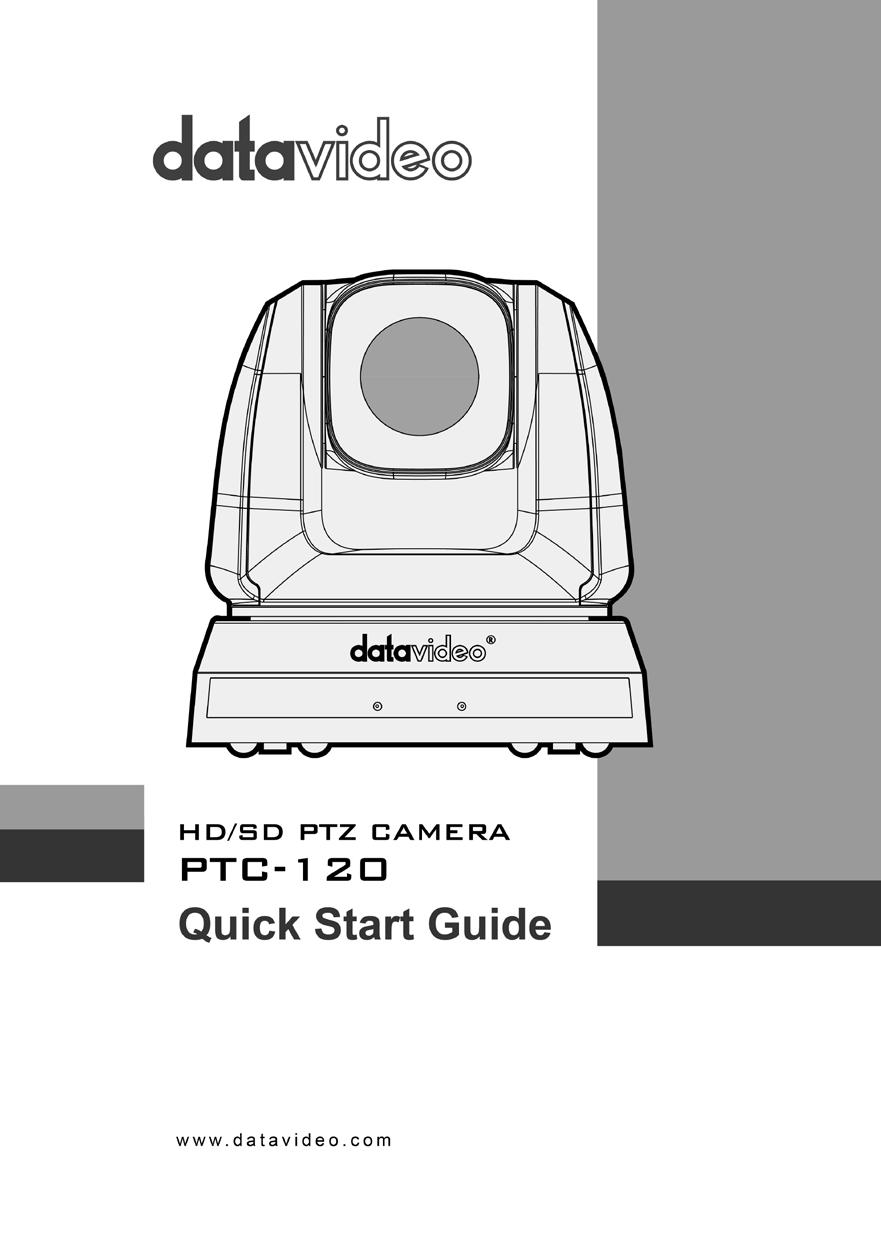
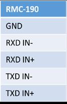
34 SONY RM-BR300 Datavideo PTC NC 1 RXD OUT- 2 NC 2 RXD OUT+ 3 NC 3 TXD OUT- 4 NC 4 TXD OUT+ 5 GND 5 GND 6 RXD IN- 6 RXD IN- 7 RXD IN+ 7 RXD IN+ 8 TXD IN- 8 TXD IN- 9 TXD IN+ 9 TXD IN+ 12 How to control multiple PTC-120 cameras using SONY RM-BR300 Keyboard Controller via RS-422 interface? Multiple PTC-120 cameras can also be connected in a daisy chain fashion. The following diagram shows the user how to cascade multiple PTC-120 cameras with SONY RM-BR300 Keyboard Controller via RS- 422 interface. 34
35 13 Control of PTC-120 using SONY s RM-BR300 Keyboard Controller on RS-232 interface Camera RS-232C Terminal The diagram below shows the user how they can connect SONY s RM-BR300 Keyboard Controller to the PTC-120 camera via RS-232 interface. SONY RM-BR300 1 DTR 1 DTR 2 DSR 2 DSR 3 TXD 3 TXD 4 GND 4 GND 5 RXD 5 RXD 6 GND 6 GND 7 IR OUT 7 OPEN 8 N.C. 8 OPEN 35
36 8. Specification Video Image Pickup Element 1/2.8 type CMOS sensor Effective Picture Elements Resolution Signal System S/N Ratio Electric Shutter Electric Sensitivity UP Gamma Iris Control Digital Noise Reductions On-Screen Display (OSD) OSD Control White Balance AGC / Gain Control Zoom Ratio Mirror Focus Mode Day & Night (IR) Approx. 2.0 Mega pixels HD / FHD 1080/ 60p, 1080/ 50p, 1080/ 60i, 1080/ 50i, 1080/ 30p, 1080/ 25p, 720/ 60p, 720/ 50p, 720/ 30p, 720/25p 50dB 1/1 ~ 1/10,000 sec N/A Yes, 4 modes Auto 2D & 3D English / Simplified Chinese IR Controller & Remote controller Auto, indoor, outdoor, one-push, manual Auto / Manual 20x Optical zoom; 12x Digital zoom Mirror / Flip Auto / Manual Color / Grey / Invert Pan / Tilt / Zoom Pan/Tilt Range Pan: 340, Tilt: +90 to -30 Pan/Tilt Speed Initialization Time Preset Coordinate Report Camera ID Camera Title Lens Type Focal Length Pan & Tilt : 300 /sec 13 sec 128 Position N/A 1~7 (VISCA) N/A Angle of View (Horizontal) 63 Lens 20x Optical Zoom, 12x Digital Zoom f = 4.7 ~ 94 mm Video Output 36
37 Video Output Video Format Output Protocol Baud Rate Remote Control Remote Controller F/W Update DVIP IR Receiver IR Control Moving Noise while Tilt (Average) Moving Noise while Pan (Average) Position Coordination Report 3G-SDI x 1 DVI-D x 1 Component x 1 CVBS x 1 1 V p-p / 75 Ohms. SONY VISCA Control 9600 / bps RS-232 & RS-422 RMC-190 By RS-232 N/A 5 IR Receivers One IR controller Others <=30dB <=30dB Yes Operating Temperature 0 ~ 45 Storage Temperature -10 ~60 Operating Humidity: Certifications Dimensions (W x H x D): Weight Accessories 20 % to 80 % (no condensation) CE / FCC Class A 6.9 x 7.3 x 7.2 (174 x 186 x mm) (W x D x H) 4.4 lbs (2.0 kg) IR Controller Mounting Bracket (for table or ceiling) Mounting Bracket (for main unit) Mounting Screws DC In Power Adaptor Power Cord 37
38 9. DIP Switch PTC-120 offers the user four types of DIP Switch and prior to installation of the device, the user must first configure these DIP switch settings. Please turn off the machine before changing DIP switch setting. The four types of DIP switch are, 1. Output Switch 2. IR Select 3. Camera Address Selector 4. System Switch 9.1 OUTPUT Switch Output switch sets the output resolution. The supported resolutions are listed in the table below. Output Resolution Setting Output Resolution Setting 1920x1080/60p 1920x1080/50p 1920x1080/30p 1920x1080/25p 1920x1080/60i 1920x1080/50i 1280x720/60p 1280x720/50p 1280x720/30p 1280x720/25p 1920x1080/59.94p 1920x1080/59.94i 1920x1080/29.97p 1280x720/59.94p 1920x720/29.97p 38

39 9.2 IR SELECT IR Select assigns the camera an identification number when the user desires to operate multiple cameras using the Remote Control (Section 5.1). ID Setting 9.3 Camera Address Selector Camera Address Selector sets the camera address used in the cascade connection scenario. The user is allowed to cascade up to 7 cameras, which are controlled via either RS-232C interface or RS-422 interface. Setting 9.4 System Switch 0 Function Descriptions Addresses are assigned to the cameras automatically in the poweron order. 1-7 Camera Address Reserved System switch adjusts the basic system settings, such as communication protocol, IR signal, and communication baud rate. 39
40 Setting DIP 1 DIP 2 DIP 3 DIP 4 Function Descriptions RS-232C/RS-422 Selector OFF: RS-232C ON: RS-422 Infrared Signal Output Switch OFF: OFF ON: ON (When turned on, CODEC, installed inside the machine, is required) Communication Baud Rate Selector OFF: 9600 ON: Reserved 9.5 Service Switch There are three firmware download modes. PAN motor firmware and TILT motor firmware are to be upgraded separately. The corresponding DIP switch configurations are listed in the table below. Before Firmware upgrade, please make sure 1. DIP 1 of the System Switch is set to OFF. 2. Camera Address Selector is set to zero. Setting Function Descriptions OFF (Default) Upgrade of Camera DSP FW/Camera Protocol FW/M3 Control FW PAN Motor Firmware Upgrade N.B. Please contact Datavideo s technical team for firmware upgrade SOP. TILT Motor Firmware Upgrade 40
41 10. Component Video Output 10.1 DSub PIN Assignments PIN No. PIN Name Signals 1 RED Red Video 2 GREEN Green Video 3 BLUE Blue Video 4 ID2/RES Reserved 5 GND Ground (HSync) 6 RED_RTN Red return 7 GREEN_RTN Green return 8 BLUE_RTN Blue return 9 KEY/PWR +5V DC 10 GND Ground (VSync) 11 ID0/RES Reserved 12 ID1/SDA I 2 C Data 13 HSync Horizontal sync 14 VSync Vertical sync 15 ID3/SCL I 2 C Clock 41
42 11. RS-232 PIN Assignments 11.1 PIN Descriptions PIN No. PIN Name Signals 1 DTR Data Transmission Read (Output) 2 DSR Data Set Read (Input) 3 TXD Transmit Data (Output) 4 GND Ground 5 RXD Receive Data (Input) 6 GND Ground 7 IR OUT IR Commander Signal (Output) 8 N.C. No Connection 11.2 Wiring Diagrams With RS-232 interface, PTC-120 can be controlled using a home PC. The diagram below shows the connection in a PC-controlled scenario. Camera RS-232C Terminal 1 DTR 1 CD PC RS-232C Terminal 2 DSR 2 RXD 3 TXD 3 TXD 4 GND 4 DTR 5 RXD 5 GND 6 GND 6 DSR 7 IR OUT 7 RTS 8 N.C. 8 CTS 9 RI 42

43 12. RS-422 PIN Assignments PTC-120 PTZ control function can be remotely controlled at any location via RS-422 interface 12.1 PIN Descriptions PIN No. Function 1 RXD OUT- 2 RXD OUT+ 3 TXD OUT- 4 TXD OUT+ 5 GND 6 RXD IN- 7 RXD IN+ 8 TXD IN- 9 TXD IN+ 43
44 12.2 Physical Connection 1. Hold the two sides of RS-422 connector and pull out in the direction indicated by the arrow in the figure below 2. Peel off a section of copper wire (AWG Nos.28 to18) and insert it into the connector hole; use a flat head screwdriver to fix the copper wire in the connector hole with a slotted screw. 44

45 3. Insert the wired RS-422 connector back into the camera to complete the connection. <Note> When RS-422 connection is being used; do not use RS-232C connection Wiring Diagrams To control PTC-120 with an external keyboard controller, establish RS-422 interface connections between PTC-120 and RMC-190 keyboard controller as shown below. RS-422 Interface on PTC
46 46
47 13. VISCA Commands Command Set Command Command Packet Comments AddressSet Broadcast FF Address setting IF_Clear Broadcast FF I/F Clear CommandCancel - 8x 2p FF p: Socket No. (=1 or 2) CAM_Power On 8x FF Off (Standby) 8x FF Power ON/OFF The power automatically turns off if the camera does not receive any VISCA commands or any signals from the Remote Control for the duration you set in the timer. CAM_AutoPowerOff Direct 8x p 0q 0r 0s FF Auto Power Off pqrs: 0000 to FFFF CAM_Zoom Stop Tele (Standard) Wide (Standard) Tele Step Wide Step Tele (Variable) Wide (Variable) Direct 8x FF 8x FF 8x FF 8x FF 8x FF 8x p FF 8x p FF 8x p 0q 0r 0s FF Power Off Timer pqrs: 0000 (Timer Off) to FFFF (65535min) Initial value: 0000 Zoom Position: 0~0x4000 p=0 (Low) to 7 (High) pqrs: Zoom Position(0x0000~0x4000) Note: Optical Zoom Tele max position: 0x4000 pqrs: Zoom Position(0x0000~0x4000) Direct (Speed Variable) 8x p 0q 0r 0s 0t FF Note: Optical Zoom Tele max position: 0x4000 t: 0~7 (0 :Low, 7:High) CAM_DZoom On 8x FF Digital zoom ON/OFF (Not used Off 8x FF in separate mode) Stop 8x FF Far (Standard) 8x FF Near (Standard) 8x FF * Enabled during Manual Mode Far Step 8x FF p=0 (Low) to 7 (High) Near Step 8x FF Far (Variable) 8x p FF Near (Variable) 8x p FF CAM_Focus Focus Position 8x p 0q 0r 0s pqrs: pqrs parameters Direct FF are in the General Zoom Focus Table from 0x00~0x1C6 Auto Focus 8x FF Manual Focus 8x FF AF ON/OFF Auto/Manual 8x FF One Push Trigger 8x FF *Enabled during manual mode One Push AF Trigger CAM_ZoomFocus Direct 8x p 0q 0r 0s pqrs: Zoom Position 47
48 0t 0u 0v 0w FF (0x0000~0x4000) tuvw: Focus Position (0x00~0x1C6) CAM_Initialize Lens 8x FF Lens Initialization Start Camera 8x FF Camera reset Resolution Setting 8x p FF p: 0x00:1080p-60 0x01:1080p-50 0x02:1080p-30 0x03:1080p-25 0x04:1080i-60 0x05:1080i-50 0x06:720p-60 0x07:720p-50 0x08:720p-30 0x09:720p-25 0x0A:1080p x0B:1080i x0C:1080p x0D:720p x0E:720p-2997 Auto 8x FF Normal Auto Indoor 8x FF Indoor Mode Outdoor 8x FF Outdoor Mode One Push WB 8x FF One Push WB mode ATW 8x FF Auto Tracing White Balance Sodium Lamp 8x FF Sodium lamp source fixed mode 3000K 8x FF Color temperature fixed at 3000K mode CAM_WB 4300K 8x FF Color temperature fixed at 4300K mode 5000K 8x FF Color temperature fixed at 5000K mode 6500K 8x FF Color temperature fixed at 6500K mode 8300K 8x A FF Color temperature fixed at 8300K mode Wide Auto 8x B FF Wide Auto One Push Trigger 8x FF *Enabled during one push WB mode One push WB trigger Full Auto 8x FF Automatic exposure mode Manual 8x FF Manual control mode CAM_AE Shutter priority automatic Shutter Priority 8x A FF exposure mode White Board 8x F FF White board mode Reset 8x A 00 FF Shutter Setting Up 8x A 02 FF * Enabled in Shutter CAM_Shutter Down 8x A 03 FF Priority/Manaual Mode Direct 8x A p 0q Shutter Position FF pq: 00 To 15 Reset 8x C 00 FF Gain Setting Up 8x C 02 FF *Enabled in manual mode Down 8x C 03 FF CAM_Gain 8x C p 0q Direct Gain Position, pq: 00 to 0F FF Gain Limit 8x C 0p FF Gain Position, p: 4 to F On 8x E 02 FF Exposure Compensation Off 8x E 03 FF ON/OFF CAM_ExpComp Reset 8x E 00 FF Exposure Compensation Up 8x E 02 FF Amount Setting Down 8x E 03 FF Direct 8x E p 0q FF ExpComp Position, pq: 00 To 0A CAM_BackLight On 8x FF Back Light Compensation 48
49 Off 8x FF ON/OFF *Enabled in AE Full Auto Mode On 8x FF Automatic Spot Exposure Setting Off 8x FF CAM_SpotAE *Enabled in AE Auto mode Position 8x p 0q 0r 0s pq: X (00 To 08) FF rs: Y (00 To 06) CAM_WD Set Parameter 8x D 0p FF p: 0 ~ 5 0: Off 1~5: mode 1~5 Reset 8x FF Up 8x FF Aperture Control CAM_Aperture Down 8x FF (Sharpness) 8x p 0q Aperture Gain Direct FF pq: 00 to 0F CAM_HR On 8x FF High Resolution Mode Off 8x FF ON/OFF CAM_2DNR 8x p FF NR Setting p: 0 to 6 0: OFF 5: Max 6: Auto CAM_2DNR 8x p FF NR Setting p: 0 to 4: 0: Off 1: Low 2: Typ 3: Max 4: Auto CAM_Gamma 8x B 0p FF Gamma Setting p: 0 to 3 CAM_LR_Reverse On 8x FF Mirror Image Off 8x FF ON/OFF CAM_Freeze On 8x FF Off 8x FF Still Image ON/OFF Off 8x FF CAM_PictureEffect Neg.Art 8x FF Picture Effect Setting B&W 8x FF CAM_PictureFlip On 8x FF Off 8x FF Picture flip ON/OFF CAM_ICR On 8x FF IR Mode Off 8x FF ON/OFF Reset 8x F 00 pp FF CAM_Memory Memory Number Set 8x F 01 pp FF (Preset) pp: 0x00 to 0x7F Recall 8x F 02 pp FF CAM_Mute On 8x FF Muting Off 8x FF ON/OFF On/Off 8x FF CAM_IDWrite 8x p 0q 0r 0s Camera ID FF pqrs: 0000 to FFFF On 8x B 02 FF Alarm ON/OFF Off 8x B 03 FF Day judgment level setting ppp: 000 to FFF 49 8x D 0p 0p 0p 0q 0q 0q FF SetDayNighLevel CAM_Day&Night Night judgment level setting Mode qqq: 000 to FFF Detection level Low -> High y B 01 FF y = camera address + 8 Alarm(Reply) Detection level High -> Low y B 00 FF y = camera address + 8 CAM_ Message reply Interval Time [Vertical ReplyIntervalTimeSet 8x A p 0p time during day timing] FF and night pp: 0x01~0xFF CAM_ChromaSuppre 8x F pp FF Chroma Suppression setting
50 ss pp:00 to 03 00: OFF 01 to 03: ON (3 levels) Suppression increases as the level number increases. CAM_ColorGain (Saturation) CAM_ColorHue IR_Receive IR_ReceiveReturn Pan-tiltDrive Direct 8x pq pq:0x00~0x19 FF Direct 8x F p FF p: 0x00~0x0E On 8x FF IR (remote control) receive Off 8x FF ON/OFF On/Off 8x FF On 8x 01 7D FF IR (remote control) receiving 8x 01 7D FF message via VISCA Off communication ON/OFF Up 3) 8x VV WW FF Down 3) 8x VV WW FF Left 3) 8x VV WW 01 Pan speed 03 FF VV: 0x01 (low speed) to 0x18 Right 3) 03 FF 8x VV WW 02 (high speed) UpLeft 3) 8x VV WW 01 Tilt Speed 01 FF WW: 0x01 (low UpRight 3) 8x VV WW 02 speed) to 0x18 (high speed) 01 FF DownLeft 3) 8x VV WW 01 VV: 0x01 to 0x18 02 FF WW: 0x01 to 0x18 DownRight 3) 8x VV WW FF Pan Position Stop 3) 8x VV WW 03 YYYY: 0000 to 0AD4 & F52C 03 FF to FFFF (center 0000) 8x VV WW 0Y AbsolutePosition 0Y 0Y 0Y 0Z 0Z 0Z 0Z FF RelativePosition Home Reset 8x VV WW 0Y 0Y 0Y 0Y 0Z 0Z 0Z 0Z FF 8x FF 8x FF Tilt Position ZZZZ: 0000 to 05C1 & FE1B to FFFF (center 0000) UpRight W: 1 Pan Limit Position YYYY: 0000~0AD4 Pan-tiltLimitSet LimitSet 8x W 0Y 0Y 0Y 0Y 0Z 0Z 0Z 0Z FF Tilt Limit Position ZZZZ: 0000~05C1 DownLeft W: 0 Pan Limit Position YYYY: FFFF~F52C LimitClear 8x W 07 0F 0F 0F 07 0F 0F 0F FF Firmware Firmware version 8x FF Read Error Code 8x FF Error Code Clear Error Code Record 8x FF Tilt Limit Position ZZZZ: FFFF~FE1B 50
51 Factory Reset CAM_Image_Mode Output Video Type System Factory Reset Select CAM Image Mode Select the output Video type 8x F FF 8x F 04 0p FF 8x F 05 0p FF Preset Speed Set Preset Speed 8x p FF Motor Table Select CAM Prompt CAM_MemSave CAM Model ID CAM_SERIAL_NINE CAM_AF_SPEED CAM_AF_SENSITIVE Select Motor Speed Table Set Prompt On/Off Write Mem Data Set Camera model ID Serial Number With 9 ascii codes Normal Fast Normal / Fast 8x p FF 8x p FF 8x X 0p 0p 0q 0q FF p: 0~6 0: Custom mode p: 0~1 0: SDI 1: YPbPr/DVI p: 0 to 2 0: 150 degree/second 1: 250 degree/second 2: 300 degree/second p = Table number 0: Default mode 1: Engineer mode p: 2 to 3 2: Prompt On 3: Prompt Off Address X: 00 to 07 (total 16 bytes) Data ppqq: 0x0000 to 0xFFFF 8x pp qq rr ss ppqq: Vendor ID FF rrss: Model ID 8x Serial Number aabbccddeeffgghhiiff aabbccddeeffgghhii: 9 ASCII codes 8x FF 8x FF AF speed: Normal/Fast 8x FF 8x p FF p: 1 to 3 1: High 2: Middle 3: Low 8x C 02 FF 8x C 03 FF Set AF frame: Full Frame / Center Full Frame Center CAM_AF_FRAME Full Frame / 8x C 10 FF Center CAM_ImageModeBri ghtness Set Brightness 8x p FF p: 0x0~0xE CAM_ImageModeCo ntrast Set Contrast 8x p FF p: 0x0~0xE CAM_Skin_Tone select red level 8x p FF p: 0~4 p: 0 to 3 0: Off Black Level Black Level 8x p FF 1: Type 1 2: Type 2 3: Type 3 Power_LoadState SYS_Menu CAM_AE_Bright_Ctrl Load Preset 0 8x A 02 FF Load preset 0 when power on when power on and reset Pan/tilt 8x A 03 FF Load last status when power on On 8x FF turn on the menu screen Off 8x FF turn off the menu screen On/Off 8x FF turn on/off the menu screen Reset 8x D 00 FF Up 8x D 02 FF AE Bright Control (Using EV) Down 8x D 03 FF 51
52 14. Service & Support 52
b. Time Setting c. Volume Setting d. Backlight Setting e. Sleep Setting f. Pin Setting g. Joystick Calibration...
 0 Warnings and Precautions... 2 Warranty... 3 Disposal... 3 1. Product Overview... 4 2. Features... 4 3. Functions... 4 4. System Diagram... 7 5. Setting Menu... 9 6. Menu operation... 10 a. Camera Setting...
Marshall Electronics
 Marshall Electronics CV620-WH & CV620-BK Full HD Broadcast PTZ Camera Installation Guide To download the latest version of Quick Start Guide, software, or driver, etc., please visit Hwww.lcdracks.com Table
CV620-BK2/WH2 Full-HD PTZ Camera
 CV620-BK2/WH2 Full-HD PTZ Camera Installation Guide Ver 1.1-100517a Table of Contents Safety Instructions... 4 Package Contents... 6 Product Overview... 7 3.1 Overview... 7 3.2 Description of LED indicator...
VC-A60S PTZ Video Camera. Installation Guide - English
 VC-A60S PTZ Video Camera Installation Guide - English [Important] To download the latest version of Quick Start Guide, multilingual user manual, software, or driver, etc., please visit Lumens http://www.mylumens.com
VC-A51S HD Camera (PTZ Video Camera) Installation Guide - English
 Installation Guide - English") VC-A51S HD Camera (PTZ Video Camera) Installation Guide - English [Important] To download the latest version of Quick Start Guide, multilingual user manual, software, or driver, etc., please visit Lumens
VC-A51S HD Camera (PTZ Video Camera) Installation Guide - English [Important] To download the latest version of Quick Start Guide, multilingual user manual, software, or driver, etc., please visit Lumens
VC-G30 Camera. Installation Guide - English
 VC-G30 Camera Installation Guide - English [Important] To download the latest version of Quick Start Guide, multilingual user manual, software, or driver, etc., please visit Lumens http://www.mylumens.com
WARNINGS AND PRECAUTIONS... 3 PACKING LIST... 5 FRONT PANEL... 5 REAR PANEL... 6 MENU SETTINGS... 7 EXAMPLE SETUP SPECIFICATIONS...
 AUDIO DELAY sax AD-1 aam Quick Start Guide WARNINGS AND PRECAUTIONS... 3 PACKING LIST... 5 FRONT PANEL... 5 REAR PANEL... 6 MENU SETTINGS... 7 EXAMPLE SETUP... 11 SPECIFICATIONS... 11 SERVICE & SUPPORT...
AUDIO DELAY BOX WITH MICROPHONE INPUT AD-100M. Instruction manual.
 AUDIO DELAY BOX WITH MICROPHONE INPUT AD-100M Instruction manual www.datavideo.com Table of Contents FCC COMPLIANCE... 3 WARNINGS AND PRECAUTIONS... 3 WARRANTY... 4 STANDARD WARRANTY... 4 THREE YEAR WARRANTY...
BC-200 Instruction Manual
 4K BLOCK CAMERA BC-200 Instruction Manual Table of Contents FCC COMPLIANCE STATEMENT... 4 WARNINGS AND PRECAUTIONS... 4 WARRANTY... 5 STANDARD WARRANTY... 5 THREE YEAR WARRANTY... 6 DISPOSAL... 7 1. INTRODUCTION...
Supplied Accessories.
 Precautions. Safety Tips. Please read this manual carefully before using the camera. Avoid damage from stress, violent vibration or liquid intrusion during transportation, storage or installation. Take
HuddleCamHD 10X-USB2
 HuddleCamHD 10X-USB2 USB 2.0 PTZ CAMERA INSTALLATION & OPERATION MANUAL Please check HUDDLECAMHD.com for the most up to date version of this document Precautions. Safety Tips. Please read this manual carefully
CM55-VCU USB 3.0 HD PTZ Camera User Manual v2.1
 CM55-VCU USB 3.0 HD PTZ Camera User Manual v2.1 www.avonic.eu 1 Safety Notes Before installing the device, please read this manual carefully and follow instructions indicated to ensure proper operation.
Supplied Accessories.
 Precautions. Safety Tips. Please read this manual carefully before using the camera. Avoid damage from stress, violent vibration or liquid intrusion during transportation, storage or installation. Take
BC-80 BLOCK CAMERA. Instruction Manual
 BC-80 BLOCK CAMERA Instruction Manual Table of Contents FCC COMPLIANCE STATEMENT... 4 WARNINGS AND PRECAUTIONS... 4 WARRANTY... 5 STANDARD WARRANTY... 5 THREE YEAR WARRANTY... 6 DISPOSAL... 7 1. INTRODUCTION...
DANNOVO HD USB 3.0 PTZ Video Conference Camera User Manual
 DANNOVO HD USB 3.0 PTZ Video Conference Camera User Manual V 2.3(ENGLISH VERSION) Please read this Manual before set up Camera, and stick to its requirements strictly for Safety reason. Suggest you save
HD SDI 1080p WDR DNR 24 IR OSD Bullet Camera
 HD21B24-940 HD SDI 1080p WDR DNR 24 IR OSD Bullet Camera USER MANUAL FEATURES SDI 1080p - 1920 x 1080 1/2.9" Sony Exmor 4.0mm Fixed Lens 0.5 Lux 24 IR LED IR distance up to 50ft / 24m 700mA max 12V DC
Prestigio P371 Users manual
 Prestigio P371 Users manual 1. IMPORTANT INFORMATION WARNING: TO PREVENT FIRE OR SHOCK HAZARD, DO NOT EXPOSE THIS MONITOR TO LIQUIDS OR MOISTURE. HIGH VOLTAGE EXISTS ON THIS MONITOR. DO NOT REMOVE THE
Nearus USB2.0 Camera Manual NU-350-USB2PTZ-B
 Nearus USB2.0 Camera Manual NU-350-USB2PTZ-B Safety Tips Please read this manual carefully before installing the camera. Keep the camera away from violent vibration, physical stress, moisture, extreme
HuddleCamHD 3x USB 2.0 PTZ CAMERA INSTALLATION & OPERATION MANUAL
 HuddleCamHD 3x USB 2.0 PTZ CAMERA INSTALLATION & OPERATION MANUAL Precautions. Safety Tips. Please read this manual carefully before using the camera. Avoid damage from stress, violent vibration or liquid
Warnings and Precautions
 Warnings and Precautions 1. Read all of these warnings and save them for later reference. 2. Follow all warnings and instructions marked on this unit. 3. Unplug this unit from the wall outlet before cleaning.
HD SDI 1080P ICR OSD 42 IR Vandal Dome Camera
 HDVDX42-4AVF HD SDI 1080P ICR OSD 42 IR Vandal Dome Camera Optional Bracket MB-4VD USER MANUAL FEATURES SDI 1080P - 1920 x 1080, 30fps, 2.0 Megapixel 1/2.8 2.0 Megapixel Progressive Scan CMOS 3.3mm~12mm
QIT600F1 USER'S GUIDE
 QIT600F1 USER'S GUIDE 1 IMPORTANT SAFEGUARDS Warnings: 1. Read all of these instructions. Save these instructions for later use, please. 2. Unplug this monitor from the wall outlet before cleaning. Do
HuddleCamHD 30x USB 3.0 PTZ CAMERA INSTALLATION & OPERATION MANUAL
 HuddleCamHD 30x USB 3.0 PTZ CAMERA INSTALLATION & OPERATION MANUAL Please check HUDDLECAMHD.com for the most up to date version of this document Precautions. Safety Tips. Please read this manual carefully
HuddleCamHD 3XA with Audio USB 2.0 PTZ Camera w/ built-in Mic Array Installation and Operation Manual
 HuddleCamHD 3XA with Audio USB 2.0 PTZ Camera w/ built-in Mic Array Installation and Operation Manual Precautions Safety Tips Please be aware any deviation from these tips may void your warranty Please
Contents. Warnings and Precautions...3. Warranty...4. Disposal...4. Packing List...5. Introduction...5. Features...6. Example MCU-100 Set Up...
 Contents Warnings and Precautions...3 Warranty...4 Disposal...4 Packing List...5 Introduction...5 Features...6 Example MCU-100 Set Up...7 Connections and Controls...8 MCU-100 Keyboard Guide...10 How to
CM-Z2212GY. Outdoor IR Speed Dome PTZ Camera
 Outdoor IR Speed Dome PTZ Camera User s Guide CM-Z2212GY 1201-1205, Sangda Mansion, High Technology Park, SAFETY PRECAUTIONS WARNING 1. Be sure to use only the standard adapter that is specified in the
HuddleCamHD 10x (Gen 3)
") HuddleCamHD 10x (Gen 3) USB 3.0 PTZ CAMERA INSTALLATION & OPERATION MANUAL Precautions. Safety Tips. Please read this manual carefully before using the camera. Avoid damage from stress, violent vibration
HuddleCamHD 10x (Gen 3) USB 3.0 PTZ CAMERA INSTALLATION & OPERATION MANUAL Precautions. Safety Tips. Please read this manual carefully before using the camera. Avoid damage from stress, violent vibration
SDI Speed Dome Camera OSD Menu
 SDI Speed Dome Camera OSD Menu Indoor/ Outdoor Ver 1.2 00P9SH720ZXSEA2 Table of Contents 1. OSD Menu Tree...4 2. Configuration Menu...7 2.1 VIDEO TYPE...8 2.2 DEFAULT CAMERA...8 2.3 BACKLIGHT...8 2.4 FOCUS...8
CONTENTS PRODUCT FEATURES... EG-2 SAFETY PRECAUTIONS... EG-2 PARTS DESCRIPTION... EG-3 INSTALLATION AND ADJUSTMENT... EG-4 SPECIFICATIONS...
 Thank you for your purchase of this product. Before operating the product, please read this instruction manual carefully to ensure proper use of the product. Please store this instruction manual in a safe
CV620-IP / CV620-IPW. Full HD PTZ Conference IP Camera. User Manual
 Full HD PTZ Conference IP Camera User Manual Table of Contents Chapter 1. Safety Instructions... 3 Chapter 2. Package Contents... 5 Chapter 3. Product Overview... 6 3.1 Overview... 6 3.2 Description of
HD/SD-SDI HDBaseT PTZ CAMERA PTC-150T/ PTC-150TW. Instruction Manual.
 HD/SD-SDI HDBaseT PTZ CAMERA PTC-150T/ PTC-150TW Instruction Manual www.datavideo.com Table of Contents TABLE OF CONTENTS... 2 FCC COMPLIANCE STATEMENT... 4 WARNINGS AND PRECAUTIONS... 4 WARRANTY... 5
Network Camera. Quick Guide DC-B1203X. Powered by
 Network Camera Quick Guide DC-B1203X Powered by Safety Precautions English WARNING RISK OF ELECTRIC SHOCK DO NOT OPEN WARNING: TO REDUCE THE RISK OF ELECTRIC SHOCK, DO NOT REMOVE COVER (OR BACK). NO USER-SERVICEABLE
Avonic AV-CON300. PTZ Camera Controller
 Avonic AV-CON300 PTZ Camera Controller User Manual Version 1.0 Update notes: Join Avonic linkedin.com/company/avonic twitter.com/avonic1 facebook.com/avonic www.avonic.eu 1 Contents Inhoud Contents...
SERVICE MANUAL 1/3 SONY DSP COLOR CCD CAMERA OVER 650TVL SERIES
 SERVICE MANUAL 1/3 SONY DSP COLOR CCD CAMERA OVER 650TVL SERIES The serial number of this product may be found on the bottom of the unit. You should note the serial number of this unit in the space provided
VC-A50P PTZ Video Camera
 VC-A50P PTZ Video Camera Installation Guide - English [Important] To download the latest version of Quick Start Guide, multilingual user manual, software, or driver, etc., please visit Lumens http://www.mylumens.com/
PTZ Conference Room USB Camera
 PTZ Conference Room USB Camera P/N 35520 User's Manual SAFETY WARNINGS AND GUIDELINES Please read this entire manual before using this device, paying extra attention to these safety warnings and guidelines.
VITEK VTD-IR2811DN FEATURES: 1/3 Color CCD with 560 TV of Lines Resolution (600 TV Lines in B/W mode)
") VTD-IR2811DN 560 TV Line Indoor Day/Night IR Dome Camera VITEK FEATURES: 1/3 Color CCD with 560 TV of Lines Resolution (600 TV Lines in B/W mode) 20 Infrared LEDs enable Viewing in Total Darkness up to
VTD-IR2811DN 560 TV Line Indoor Day/Night IR Dome Camera VITEK FEATURES: 1/3 Color CCD with 560 TV of Lines Resolution (600 TV Lines in B/W mode) 20 Infrared LEDs enable Viewing in Total Darkness up to
PTZ and Block Camera Control Protocol. JAN 15 th, 2019
 Rev 1.8 PTZ and Block Camera Control Protocol JAN 15 th, 2019 Model: BC-80, BC-80T, BC-200, BC-200T, PTC-150, PTC-150T, PTC-200, PTC-200T Datavideo Technologies Datavideo PTZ/Block Camera VISCA Commands
VC-B10U HD Camera (USB 3.0 Camera) Installation Manual - English
 Installation Manual - English") VC-B10U HD Camera (USB 3.0 Camera) Installation Manual - English [Important] To download the latest version of Quick Start Guide, multilingual user manual, software, or driver, etc., please visit Lumens
VC-B10U HD Camera (USB 3.0 Camera) Installation Manual - English [Important] To download the latest version of Quick Start Guide, multilingual user manual, software, or driver, etc., please visit Lumens
CV620-IP / CV620-IPW. Full HD PTZ Conference IP Camera. User Manual. Document Updated 7/11/18
 Full HD PTZ Conference IP Camera User Manual Document Updated 7/11/18 Table of Contents Chapter 1. Safety Instructions... 3 Chapter 2. Package Contents... 5 Chapter 3. Product Overview... 6 3.1 Overview...
TEK 380-HD HDMI/SDI Conference Camera User s Guide
 TEK 380-HD HDMI/SDI Conference Camera User s Guide TEK 380-HD Conference Camera V031015 Table of Contents Overview... 4 Main Features... 4 Camera and Lens... 5 Pan/Tilt Movement... 5 Rear Connectors...
1. Introduction Features Checking List Installation Install the Pedestal Connect Your Monitor to Computer...
 E27M5G 27 " W User Manual M Series L E D B A C K L I G H T M o n i to r Content F.C.C STATEMENT IMPORTANT SAFEGUARDS 1. Introduction 6 1.1 Features...6 1.2 Checking List...6 2. Installation 7 2.1 Install
HDC-SDOMEO51MIR-B USER MANUAL. HD Portable Rugged PTZ Cameras
 HDC-SDOMEO51MIR-B USER MANUAL HD Portable Rugged PTZ Cameras Safety Notes Thank You for Choosing Our HD table Rugged PTZ Camera! When you open the box: 1. Check that the packing and the contents are not
FCB-EV Series Color Block Camera
 FCB-EV Series Color Block Camera FCB-EV7100 FCB-EV5500 FCB-EV5300 FCB-EV7500 FCB-EV7300 FCB-EV7310 * This brochure is published based on the features and specifications for firmware Version 0310. Introduction
TURBO HD D7T Series Dome Camera
 TURBO HD D7T Series Dome Camera User Manual UD02018B User Manual Thank you for purchasing our product. If there are any questions, or requests, do not hesitate to contact the dealer. This manual applies
Motion LED Floodlight Covert Color Camera
 ESFL-X650 Operational Manual Motion LED Floodlight Covert Color Camera Camera FEATURES 1/3 Sony ExView HAD CCD II 650 TV Lines (Color) / 700TV Lines (B&W) 3.6mm Board Lens 0.01 Lux @ F2.0; 0 Lux @ IR on
CONTENTS PRODUCT FEATURES... EG-2 SAFETY PRECAUTIONS... EG-2 PARTS DESCRIPTION... EG-3 INSTALLATION AND ADJUSTMENT... EG-4 SPECIFICATIONS...
 Thank you for your purchase of this product. Before operating the product, please read this instruction manual carefully to ensure proper use of the product. Please store this instruction manual in a safe
DC-D4213RX DC-D4213WRX
 Network Camera Quick Guide DC-D4213RX DC-D4213WRX Powered by Safety Precautions WARNING RISK OF ELECTRIC SHOCK DO NOT OPEN WARNING: TO REDUCE THE RISK OF ELECTRIC SHOCK, DO NOT REMOVE COVER (OR BACK).
DAY AND NIGHT COLOR CAMERA
 INSTRUCTION MANUAL DAY AND NIGHT COLOR CAMERA MODEL HDC518 Copyright 2007 Clover Electronics U.S.A. All Rights Reserved. PRECAUTIONS To avoid electrical shock, do not open the case of this product. Operate
PL1500M LCD Monitor USER'S GUIDE.
 PL1500M LCD Monitor USER'S GUIDE www.planar.com Content Operation Instructions...1 Safety Precautions...2 First Setup...3 Front View of the Product...4 Rear View of the Product...5 Quick Installation...6
PTZ Camera. for HDVS-300 Soft Codec Conferencing System. Application Programming Interface. Atlona Manuals Accessories AT-HDVS-CAM
 PTZ Camera for HDVS-300 Soft Codec Conferencing System Application Programming Interface AT-HDVS-CAM Atlona Manuals Accessories Version Information Version Release Date Notes 1 4/18 Initial release AT-HDVS-CAM
The Symphony Keyboard is available with either a 2D or 3D joystick. The 3D Joystick controls zoom in and out, as well as direction.
 1 SYMPHY KEYBOARD 2 Overview The Symphony Keyboard is available with either a 2D or 3D joystick. The 3D Joystick controls zoom in and out, as well as direction. The unit provides all the functions required
SECTION 1 GENERAL DESCRIPTION
 1-1 IMPORTANT SAFEGUARDS 1. Read Instructions All the safety and operating instructions should be read before the product is operated. 2. Retain Instructions The safety instructions and instruction manual
NTSC/PAL. 3CCD Color Video Camera BRC-300 BRC-300P
 NTSC/PAL 3CCD Color Video Camera P MAIN FEATURES Superb Picture Quality with a Mega Pixels 3-CCD Sony s new is a revolutionary all-in-one compact robotic color video camera system, specially designed for
HuddleCamHD SimplTrack2
 Page1 HuddleCamHD SimplTrack2 Auto Tracking Camera Installation & Operation Manual Page2 Table of Contents. Precautions Safety Tips............... Page 3 What s in the Box.............. Page 3 Physical
7 Series HD SDI+IP Dual Output PTZ Camera
 7 Series HD SDI+IP Dual Output PTZ Camera USER MANUAL VERSION: VCC-7HDSN-M-10162017 Part One VCC-7HD20S-2SMN VCC-7HD30S-2SMN 2017 Bolin Technology 1 Contents IMPORTANT INFORMATION... 3 WHAT S IN THE BOX...
USER MANUAL. For XLCD17-LED XLCD19-LED
 USER MANUAL For XLCD17-LED XLCD19-LED 2 TABLE OF CONTENTS CE information ------------------------------------------------------------------------ 4 Safety Precautions -------------------------------------------------------------------
SERVICE MANUAL 1/3 SONY DSP COLOR CCD CAMERA 600TVL O.S.D. WDR SERIES
 SERVICE MANUAL 1/3 SONY DSP COLOR CCD CAMERA 600TVL O.S.D. WDR SERIES The serial number of this product may be found on the bottom of the unit. You should note the serial number of this unit in the space
Warning! It will cause malfunction if the monitor is operating with unspecified power supply adaptor or incorrect power voltage. Do not expose this
 User Manual / Installation Guide Model No. P150VR/P150VG Warning! It will cause malfunction if the monitor is operating with unspecified power supply adaptor or incorrect power voltage. Do not expose this
FCB-EV Series. Colour Block Cameras FCB-EV7500 FCB-EV7300 FCB-EV7310 FCB-EV7100 FCB-EV5500 FCB-EV
 FCB-EV7500 FCB-EV7300 FCB-EV5500 FCB-EV7310 FCB-EV5300 FCB-EV Series Colour Block Cameras FCB-EV7500 FCB-EV7300 FCB-EV7310 FCB-EV5500 FCB-EV5300 IMAGE IMAGE SENSING SOLUTIONS Colour Block XCD Camera MV6
DNR Super Low Lux Day & Night OSD Box Camera
 SDNR-8630 SDNR-8630P Digital Noise Reduction DNR Super Low Lux Day & Night OSD Box Camera * Lens not included FEATURES USER MANUAL Optional External IR SDNR-8IR14 See page 14 for details 1/3 Sony Super
Quick Start Guide. Thank you for purchasing our products. Please read the cut-sheet carefully before operating. Safety Precaution
 Quick Start Guide Item Number: IV-BV7660IR-AHDM Thank you for purchasing our products. Please read the cut-sheet carefully before operating. Safety Precaution Warning * To prevent fire or shock hazard,
VS-K20 Compact Camera Controller. User Manual English
 VS-K20 Compact Camera Controller User Manual English [Important] To download the latest version of Quick Start Guide, multilingual user manual, software, or driver, etc., please visit Lumens http://www.mylumens.com
HD Mini Square Camera. Key Features
 HD Mini Square Camera 1080p (1920 x 1080) @ 30fps (Standard) Easy Installation (HD Over Coax (BNC)) Board Lens f= 3.6mm or 6.0 mm HD-SDI (Serial Digital Interface Type Video Output) Selectable TV Out (NTSC
HuddleCamHD SimplTrack
 Page1 HuddleCamHD SimplTrack Auto Tracking Camera Installation & Operation Manual Page2 Table of Contents. Precautions Safety Tips............... Page 3 What s in the Box.............. Page 3 Physical
DC-D2212R / DC-D2212WR
 Network Camera Quick Guide / DC-D2212WR Powered by Safety Precautions WARNING RISK OF ELECTRIC SHOCK DO NOT OPEN WARNING: TO REDUCE THE RISK OF ELECTRIC SHOCK, DO NOT REMOVE COVER (OR BACK). NO USER-SERVICEABLE
PTZ Optics Affordable HDMI, HD-SDI, IP and USB video conferencing cameras
 PTZ Optics Affordable HDMI, HD-SDI, IP and USB video conferencing cameras as PTZ Optics Affordable HDMI, HD-SDI, IP and USB video conferencing cameras as P T Z OPTICS 12X USB PTZ OPTICS Video Conferencing
Aegis Electronic Group FCB-EV7520 FCB-EV7320
 FCB-EV7520 FCB-EV7320 FCB-EV7500 FCB-EV7300 FCB-EV7310 FCB-EV5500 FCB-EV5300 FCB-EV Series Colour Block Cameras FCB-EV7520 FCB-EV7320 FCB-EV7500 FCB-EV7300 FCB-EV7310 FCB-EV5500 FCB-EV5300 IMAGE IMAGE
FCB-EV Series. Colour Block Cameras FCB-EV7500 FCB-EV7300 FCB-EV7520 FCB-EV7320 FCB-EV7310 FCB-EV7100 FCB-EV5500 FCB-EV5300
 FCB-EV7520 FCB-EV7320 FCB-EV7500 FCB-EV7300 FCB-EV5500 FCB-EV7310 FCB-EV5300 FCB-EV Series Colour Block Cameras FCB-EV7520 FCB-EV7320 FCB-EV7500 FCB-EV7300 FCB-EV7310 FCB-EV5500 FCB-EV5300 IMAGE IMAGE
INSTALLATION MANUAL. ST-BT1000IR2812-G Varifocal IR Bullet Camera. v1.0 8/4/14 1
 INSTALLATION MANUAL ST-BT1000IR2812-G Varifocal IR Bullet Camera v1.0 8/4/14 1 This package contains: PACKAGE CONTENTS One ST-BT1000IR2812-G varifocal infrared bullet color camera Mounting Hardware One
NTSC/PAL. 3CCD Color Video Camera BRC-300 BRC-300P
 NTSC/PAL 3CCD Color Video Camera BRC-300 BRC-300P MAIN FEATURES Superb Picture Quality with a Mega Pixels 3-CCD Sony s new BRC-300 is a revolutionary all-in-one compact robotic color video camera system,
Xvision AHD 2.0 Professional Camera Range XHD. OSD Guide. Thank you purchasing your Xvision AHD 2.0 camera from Xvision.
 XHD XHD XHD XHD HD 1080P Xvision AHD 2.0 Professional Camera Range OSD Guide Thank you purchasing your Xvision AHD 2.0 camera from Xvision. Please ensure that you read and understand this OSD Guide before
Monochrome Camera. Features. User manual
 Monochrome Camera LTC0330/11 LTC0330/21 LTC0350/11 LTC0350/21 LTC0330/51 LTC0330/61 LTC0350/51 LTC0350/61 Features To obtain the best results from your new camera, read these instructions carefully before
User s Manual. MON-121 Series TFT monitor. Models
 User s Manual MON-121 Series 12.1 TFT monitor Contents Models --------------------------------------------------------------------------------------------1 Unpack --------------------------------------------------------------------------------------------1
WIDE DYNAMIC RANGE CAMERA USER MANUAL
 WIDE DYNAMIC RANGE CAMERA USER MANUAL Contents 1. SAFETY PRECAUTIONS... 2 2. INTRODUCTION... 3 3. FEATURES... 4 4. PACKING LIST... 5 5. NAME and FUNCTION of EACH PART... 6 6. INSTALLATION... 8 6.1 Native
Professional Pan Tilt Zoom Camera ST-HD-PTZ-2MP INSTALLATION MANUAL
 Professional Pan Tilt Zoom Camera ST-HD-PTZ-2MP INSTALLATION MANUAL www.nacebrands.com www.securitytronix.com Description: The ST-HD-PTZ-2MP is a professional-grade intelligent dome color camera with Pan/Tilt/Zoom
FastCam Outdoor Speed Dome Camera
 FastCam Outdoor Speed Dome Camera CC-9760 & CC-9760-I USER INSTRUCTION MANUAL Version: V1.2 Doc No.: 20051114001 1 A BOUT THIS GUIDE Conventions used in this guide To make sure that you perform certain
HD SDI 1080P ICR 360 Fisheye Indoor Camera
 HD5FE-8012 HD SDI 1080P ICR 360 Fisheye Indoor Camera USER MANUAL FEATURES SDI 1080P - 1920 x 1080 SDI / HDMI / 4 Channel CVBS Output 1/3.2 Color CMOS QSXGA 5 Megapixel 1.19mm Megapixel Lens Built-in Microphone
5 B&W Rear View System Camera
 5 B&W Rear View System Camera Instruction Manual MODEL: CA453 www.lorexcctv.com Copyright 2007 LOREX Technology Inc. Thank you for purchasing the Lorex 5 Black & White Rear View System Camera. This system
3G/HD/SD-SDI Pattern Generator. User Manual
 3G/HD/SD-SDI Pattern Generator User Manual The 1B-SDI-PTG 3G-HD/SD SDI Pattern Generator has been tested for conformance to safety regulations and requirements, and has been certified for international
HD CCTV Digital Video Camera
 HD CCTV Digital Video Camera OPERATION MANUAL M133-HDX210-001 Thank you for choosing our high quality camera. Before attempting to connect or operate, please read and follow these instructions. CAUTION
Table of Contents. Federal Communications Commission (FCC) Statement...2
 Statement...2") Contents Table of Contents Federal Communications Commission (FCC) Statement...2 Important Safety Instructions...3 Chapter 1 Introduction Features...6 Package Contents...7 Front View and Controls...8 Installing
Contents Table of Contents Federal Communications Commission (FCC) Statement...2 Important Safety Instructions...3 Chapter 1 Introduction Features...6 Package Contents...7 Front View and Controls...8 Installing
Camera Installation Manual Ver 1.0. Pan, Tilt and Zoom Dome Camera / PTZ
 Camera Installation Manual Ver 1.0 1 Introduction Features 3 Components 4 System Configuration 5 2 Installation Wall Mount 6 Ceiling Mount 7 Final Assembly 8 3 Camera Addressing Camera Address Setting
EVO-TM2A EVO-TM2B Touch Screen Monitor
 User Manual Revision v1.3 Dec. 2010 EVO-TM2A EVO-TM2B Touch Screen Monitor Copyright 2010 August All Rights Reserved Manual Version 1.3 Part Number: The information contained in this document is subject
The inclusion of an 3G-SDI interface output supports longer cable lengths than HDMI, making the camera ideal for integration in large rooms.
 SRG-120DS Full HD remotely operated PTZ camera Overview Desktop PTZ camera for corporate, educational and government applications, with 3G-SDI output and 12x optical zoom. The SRG-120DS desktop PTZ camera
HD/SD-SDI HDBaseT PTZ CAMERA PTC-150T/ PTC-150TW. Instruction Manual.
 HD/SD-SDI HDBaseT PTZ CAMERA PTC-150T/ PTC-150TW Instruction Manual www.datavideo.com Table of Contents FCC COMPLIANCE STATEMENT... 4 WARNINGS AND PRECAUTIONS... 4 WARRANTY... 6 STANDARD WARRANTY... 6
TABLE OF CONTENTS ADJUSTING YOUR LCD MONITOR
 TABLE OF CONTENTS ADJUSTING YOUR LCD MONITOR -------------- 2 General safety precautions. 2 Unpacking your monitor 5 Viewing angle 6 How to open the back cover 6 Connecting your monitor 7 User controls
VZ-TVI-B3040MZVF 3MP Motorized VF EXIR Bullet Camera
 VZ-TVI-B3040MZVF 3MP Motorized VF EXIR Bullet Camera User Manual User Manual Thank you for purchasing our product. If there are any questions, or requests, please do not hesitate to contact the dealer.
INSTRUCTION MANUAL Ver 3.0. Indoor Pan, Tilt and Zoom Dome Camera / ACD-1000-LG27
 INSTRUCTION MANUAL Ver 3.0 Indoor 1 Introduction Features 3 Components 4 System Configuration 5 2 RS485 and PTZ Basics Physical Connection 6 Multiple PTZ Setup 7 ID, Protocol, Baud Rate 9 3 Installation
7 Series HD PTZ Camera
 7 Series HD PTZ Camera USER MANUAL VERSION: VCC-7HD-M-11142018 VCC-7HD20S-2SMC VCC-7HD30S-2SMC 2018 Bolin Technology 1 Contents IMPORTANT INFORMATION... 3 WHAT S IN THE BOX... 5 OVERVIEW... 6 CAMERA VERSION...
ST-HDC2FD QUICK START GUIDE. Or contact technical
 ST-HDC2FD QUICK START GUIDE www.nacebrands.com www.securitytronix.com User Manual Thank you for purchasing our product. If there are any questions, or requests, please do not hesitate to contact the dealer
User Manual. Stoltzen SHSP14 HDMI Splitter 1x4. 4K HDMI Splitter 1x4. All Rights Reserved. Version: SHSP14_2016V2
 User Manual 4K HDMI Splitter 1x4 All Rights Reserved Version: SHSP14_2016V2 SAFETY PRECAUTIONS To insure the best from the product, please read all instructions carefully before using the device. Save
9.2 TFT LCD COLOR MONITORING SYSTEM With 2 Indoor/Outdoor Color Cameras
 INSTRUCTION MANUAL 9.2 TFT LCD COLOR MONITORING SYSTEM With 2 Indoor/Outdoor Color Cameras MODEL: LCD0935 Copyright 2009 Wisecomm. All Rights Reserved. 1. IMPORTANT SAFETY PRECAUTIONS To prevent fire or
ST-PTZ High-Speed Intelligent Dome PTZ Color Camera
 INSTALLATION MANUAL ST-PTZ550-27 High-Speed Intelligent Dome PTZ Color Camera Copyright North American Cable Equipment, Inc. 1 PACKAGE CONTENTS This package contains: One ST-PTZ550-27 high-speed intelligent
HD SDI 1080p Optical Zoom & Auto Focus Box Camera
 HD21T-K10 HD21T-K4 International Patent Registered: PCT/KR2011/007613 & 7656 & 8080 HD SDI 1080p Optical Zoom & Auto Focus Box Camera USER MANUAL Auto ZF Camera Made in Korea Auto ZF Lens Made in Korea
TURBO HD TVI Bullet & Turret Camera
 TURBO HD TVI Bullet & Turret Camera User Manual UD03589B User Manual Thank you for purchasing our product. If there are any questions, or requests, do not hesitate to contact the dealer. This manual applies
Marshall Electronics. User Manual CV610-U3. Full HD Teleconference PTZ USB3.0 Camera. Ver. 2.0
 Marshall Electronics CV610-U3 Full HD Teleconference PTZ USB3.0 Camera User Manual Ver. 2.0 1 Operating Instructions OPERATING INSTRUCTIONS... 3 WHAT S IN THE BOX... 5 FEATURES... 6 CAMERA DIAGRAMS...
VITEK VTC-C680 VTC-C750. 1/3 Color Camera Series. 1/3" Super HAD CCD With 550 TVL (VTC-C750 / VTC- C750DN) & 480 TVL (VTC-C680 / VTC-C680DN)
 & 480 TVL (VTC-C680 / VTC-C680DN)") VTC-C680 VTC-C750 1/3 Color Camera Series VITEK 1/3" Super HAD CCD With 550 TVL (VTC-C750 / VTC- C750DN) & 480 TVL (VTC-C680 / VTC-C680DN) Minimum Illumination 0.02 Lux (F1.2) (VTC-C680DN / VTC- C750DN)
VTC-C680 VTC-C750 1/3 Color Camera Series VITEK 1/3" Super HAD CCD With 550 TVL (VTC-C750 / VTC- C750DN) & 480 TVL (VTC-C680 / VTC-C680DN) Minimum Illumination 0.02 Lux (F1.2) (VTC-C680DN / VTC- C750DN)
Marshall Lynx LCD Universal Monitors
 Marshall Lynx LCD Universal Monitors User Manual Marshall Industrial Video/Security Div. For more information, contact Marshall Electronics, Industrial Video & Security (800) 800-6608 www.mars-cam.com
Color Speed Dome Camera. Manual
 Color Speed Dome Camera Manual Contents 1. Safety Precautions...2 2. Symbol Description...3 3. Features...4 4. Package List...5 5. Component and Structure Description...6 6. Camera Setting...8 7. Installation...13