UCIT LIVE HD 4 Camera DVR. Installation Manual. 1/18 Version 1.0
|
|
|
- Brianna Annis Montgomery
- 6 years ago
- Views:
Transcription


1 UCIT LIVE HD 4 Camera DVR Installation Manual 1/18 Version 1.0
2 This is a step by step guide that will walk you through installing the UCIT LIVE HD 4 Channel Camera System. Basic wiring experience and knowledge is required at the minimum. Please follow each step, otherwise your system may not work properly. If you have any questions regarding the installation of this system contact Support at Press #6 or Support@SafetyTrack.net. We are always available for questions when needed. Please take your time, take caution and Enjoy! Tools Required: Power Drill Volt Meter Wire Crimpers Wire Strippers Electrical Tape Zip Ties Wire Connectors (Installer s Choice ex.t-tap, ring connector, or simply poke and wrap) Extra wire (Shouldn t need but just in case) Screwdrivers (flat head and Philips) Self Tapping Screws 3M Double Sided Trim Tape* Auto trim removal tool* Flashlight* What s In The Box: DVR SD Card (if applicable) Power Harness (6 Pin) Input Harness (10 Pin) (If Applicable) GPS Antenna Communication Antenna Microphone (If Applicable) Microphone Extension (If Applicable)
3 Notes and Precautions Please make sure power connections are clear to you before you make the connection. Please Follow this Guide STEP BY STEP do not skip around. It is normally required to have a professional installer install these units. Keep DVR System away from liquids, heavy dust and dirt, fire and extreme temperatures. If possible keep the equipment in a well ventilated area. Review packing list or whats in the box to make sure you have everything. NOTE: Any modifications to the device or software outside of company standards without company approval are not a responsibility of Safety Track and will void the warranty. Getting Started: Familiarize yourself with the contents of the box. Plan where the DVR will be mounted and how you will run the cameras before you connect to a power source. Also keep in mind any special instruction from Sales Rep or Customer on mounting location of the DVR, cameras and antennas. Remember to conceal all wires and cabling the best as possible unless otherwise directed.
 The DVR can also be hidden if requested.")


4 Step 1: Find a suitable location to mount the DVR in such a way that is accessible to the fleet manager. (To pull SD card and for troubleshooting) The DVR can also be hidden if requested. Step 2: After unboxing the equipment, and getting acquainted with what s included, start by plugging in accessories. A. Plug in and run the GPS Antenna. (square shaped) Anywhere that has a direct sightline to the sky for best reception. B. *Verizon and WIFI Models Only. Attach the blade communication antenna to the gold threaded nob protruding from the DVR. In most cases it is best to use the antenna extension provided so you can mount it away from the DVR to ensure optimum performance. A B C To the right is an example of a mounting location. Comm is adhered to a window or windshield of the vehicle. Another commonly placed location for Comm is in the A pillar. This way the Comm is out of sight. The same goes for the GPS Antenna. When it comes to the GPS specifically, make sure that the GPS receiver is sticker side down. A B C. Plug in the Accessory Harness for the microphone (If Applicable). Follow the steps below to ensure proper connection of the microphone: C
 White Wire Only 3 Find the Microphone")
 from Microphone 5 6 Find")
 on the Find the")
 from Microphone Extension")
 from Microphone Extension into Red Plug")
5 C DVR Find the Accessory Harness RCA (Female) White Wire Only 3 Find the Microphone Extension Yellow RCA (Male) and Red plug (Female) 4 Plug the Yellow RCA (Male) from Microphone 5 6 Find the Power Plug the Black Plug (Male) from the Power Harness into the Red Plug (Female) on the Find the Microphone White RCA (Female) and Red Plug (Female) 7 8 Plug Yellow RCA (Male) from Microphone Extension into White RCA (Female) on Microphone Plug Red Plug (Male) from Microphone Extension into Red Plug (Female) on Microphone


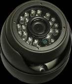
6 Place the Microphone so that it is visible and in an optimum position to get the best clarity. Pictured right is a recommended placement example. Driver side A-Pillar, this way it is near the driver. Step 3: Mount the cameras as directed or as needed. Each camera is individually packaged with mounting hardware supplied. Every camera type is different when it comes to mounting or adjustment. Following are a few examples of camera mounts and positions. Camera Model: ST-1252 Ensure cameras are aimed properly by adjusting screws or post wheel. The Screws adjust the camera tilt and the wheel adjusts camera position. In the example to the right the camera is mounted with the supplied 3M Trim tape. This Camera is placed in the upper corner of the windshield on the passenger side for a driver view. This is a very versatile camera because it can be mounted to achieve specific angles as well as be mounted in or on the exterior. Camera Model: ST-1231 Ensure cameras are properly aimed by adjusting the 4 screws on both sides of the camera shown at the right. This camera example, as you can see, has also been mounted with 3M trim tape. The bracket attached to this camera is steel and will allow for screw mounting a a bit easier. This camera type is typically placed on the exterior of a vehicle. Much like the ST-1252, its weatherproof. In the example to the right you see it being mounted to achieve an exterior rear view.


 Camera there is a small grove etched into the back.")


7 This camera can also be used as a side mount. Simply by using the hardware supplied in the box. To the right you will see the hardware required to adjust the bracket to either side of the camera. Place the raised plastic mount on the top and the bottom of the camera, use the small screws to mount the plastic piece. Once you have the raised plastic piece mounted you can fit the bracket and secure with an Allen screw. Finished product shown to the right. This view is beneficial to capture common side swipe incidents or to capture blind spots. Camera Model: ST-1225A When it comes to the interior (Non-IVR) Camera there is a small grove etched into the back. (Shown Right) This indicates when the camera is up right and in the proper position. Etching should line up with the T in the bracket. You may need to adjust the screws with the Phillips driver, Not Included. This will allow you to adjust the mounting stand angle. This will also loosen the bracket holding the camera so you can rotate it if needed. Be sure to line up the groove etched into the back of the camera to ensure a straight and proper position. Example to the right shows a popular mounting position on a vehicle s windshield (interior). This would require rotating the camera inside the bracket by loosening the bracket screw.


 plugs into the corresponding camera extension (Female).")
8 Step 4: Run camera cables with supplied 5 meter extension cables. Ensure proper connection, use electrical tape if needed. DVR Pigtails: V - Video Output A - Audio Output N/A 1. Camera 1 Video Input 2. Camera 2 Video Input 3. Camera 3 Video Input 4. Camera 4 Video Input *If monitor is used for a backup camera view, make sure the camera you want to use as a backup camera is plugged into Camera 1 Video input. This step describes how to plug in the cameras and mounting. Which ever you prefer to do first. In most cases it is easier to mount the cameras as long as you know you will have enough cable. NOTE: Be sure to line up the arrows on both ends of this connection otherwise the cameras won t connect and you could damage the pins. To the right you will see Channel 1 from the DVR (Male) plugs into the corresponding camera extension (Female). The other end of the extension (Male) Plugs into the pigtail coming from each camera you will need to line up this connection as well. NOTE: Line the groves up for a fit. No Force Lastly, and a very important step is to create a watertight seal, using the supplied seal, pictured to the right. Find the How To Video on our website.
 2. Ignition (Blue) 3. Power (Yellow) 4. N/A 5. Microphone Ground 6. Microphone Power Make the connection then attach 6 pin to DVR.")

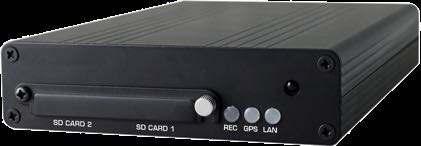
9 Step 6: Run the power cable to a power source. Typically the ignition harness under the driver side steering wheel. Test and make sure you have a constant power source and a proper ignition source. 1. Ground (Black) 2. Ignition (Blue) 3. Power (Yellow) 4. N/A 5. Microphone Ground 6. Microphone Power Make the connection then attach 6 pin to DVR. Step 7: Ensure proper connection by checking the lights on the DVR. If you see lights then you have power. It may take a few seconds for lights to come on after you connect. Red = Recording. Blue = GPS. Orange = Network. -Red will consistently blink every second or so to indicate recording and writing to the memory card. -Blue will be solid when GPS Lock is achieved. -Orange will be solid when connected to the network. Clean up! INSTALLATION COMPLETE!
UCIT LIVE HD 4 Camera DVR. Installation Manual. 10/17 Version 2.0
 UCIT LIVE HD 4 Camera DVR Installation Manual 10/17 Version 2.0 This is a step by step guide that will walk you through installing the UCIT LIVE HD 4 Channel Camera System. Basic wiring experience and
UCIT LIVE 4 Channel Installation Manual
 UCIT LIVE 4 Channel Installation Manual 06/15 Version 2.0 This is a step by step guide that will walk you through installing the UCIT LIVE 4 Channel Camera System. Basic wiring experience and knowledge
UCIT LIVE HD 4 Camera DVR. Installation Manual. 10/17 Version 2.0
 UCIT LIVE HD 4 Camera DVR Installation Manual 10/17 Version 2.0 Always Check https://www.safetytrack.net/camera-installation-and-user-manuals/ for the most up to date version of this installation guide.
UCIT BASIC-LIVE 2 CAMERA Vehicle Video Recorder Installation Manual
 UCIT BASIC-LIVE 2 CAMERA Vehicle Video Recorder Installation Manual 2015 JUN V 1.1 Table of Contents A. Features. 1 B. Specifications.2-3 C. Notices. 4 D. What s in the Box/Tools Required 5 D. Structure
Vehicle Video Recorder Installation Manual
 UCIT LIVE HD DASH CAM Vehicle Video Recorder Installation Manual 2017 APR V 1.2 Table of Contents A. Features. 1 B. Specifications.2-3 C. Notices. 4 D. What s in the Box/Tools Required 5 D. Structure of
Dual Mount Universal Kit Aftermarket CMOS Camera with Optional Parking Gridlines Installation Instructions (Kit # )
") Please read thoroughly before starting installation and check that kit contents are complete. Items Included in Kit: Chassis Harness Power Harness with RCA connectors Camera mounted on license plate bracket
Please read thoroughly before starting installation and check that kit contents are complete. Items Included in Kit: Chassis Harness Power Harness with RCA connectors Camera mounted on license plate bracket
KP1S Installation Guide with INT1S Power Adaptor
 KP1S Installation Guide with INT1S Power Adaptor 1. KP1S Windshield Mounting Apply provided 3M VHB adhesive pad to the mounting bracket and press firmly to adhere. Clean the windshield with alcohol and
INSTALLATION INSTRUCTIONS
 2015 F-150 8 MyTouch factory display 360º Vision System (Kit # AVMS-3618) DUE TO THE COMPLEXITY OF THIS KIT PROFESSIONAL INSTALLATION IS REQUIRED CALIBRATION KIT IS REQUIRED FOR FINAL PROGRAMMING -Must
INSTALLATION INSTRUCTIONS
 GM camera interface for vehicles with a factory Rear Entertainment System (RES) (Kit # 9002-2764) Please read thoroughly before starting installation and check that kit contents are complete. Items Included
INSTALLATION INSTRUCTIONS
 Dual Camera Interface for Ford MyTouch 8 Display Screen (Kit # 9002-2781) Please read thoroughly before starting installation and check that kit contents are complete. Items Included in the Kit: Interface
GMNAV1 Advent Integrated Navigation
 GMNAV1 Advent Integrated Navigation This interface is designed to integrate Navigation into select Buick and Chevrolet Systems. INSTALLATION MANUAL What s in the Box The following items are supplied with
Integrated Video Camera Installation Guide
 Integrated Video Camera Installation Guide Always mount the camera in an area cleaned by the wiper travel, and within the top 2 inches of the wiper sweep area on heavy trucks. You will need a PH0/1 size
INSTALLATION INSTRUCTIONS
 UTV/Rockcrawler Quad Camera and DVR Monitor (Kit #SUTV-1040) Please read thoroughly before starting installation and check that kit contents are complete. Items Included in the Kit: Roll Bar Mounts (1.5
Written By: Walter Galan
 imac Intel 21.5" EMC 2428 CPU Replacement Replace the CPU in your imac Intel 21.5" EMC 2428. Written By: Walter Galan ifixit CC BY-NC-SA www.ifixit.com Page 1 of 33 INTRODUCTION Use this guide to upgrade
Mobile Digital Video System
 Mobile Digital Video System Install/User Guide r4 Please read this user manual completely before operating this DVR system and keep it in a safe place for future reference. CD-ROM The CD below contains
SmartWitness KP1S + SVC400
 SmartWitness KP1S + SVC400 Installation Guide v.1.2 + WARNING: SmartWitness installations should be performed by a qualified individual or installation professional only. Working with a vehicle's power
SmartWitness CP1. Installation Guide. v.1.3
 SmartWitness CP1 Installation Guide Model # s: v.1.3 CP1 (AT&T, T-Mobile, N. & S. America HSPA networks) CP1-VZ (Verizon) CP1-SP (Sprint) WARNING: SmartWitness installations should be performed by a qualified
Raven Adapter Harness
 Note: Indented items indicate parts included in an assembly listed above Quantity by System Part Name/Description Part Number With Switch Box With Built-in Switches Raven Harness Adapter Kit 4100504 1
PLCMTR Commercial Grade Camera System
 Please read instructions carefully before installation and use. Installation should be performed by a professional installer. To ensure your safety, the driver should not watch videos or operate features
NNG-Ford V1 NTV-KIT558. Navigation interface for FORD vehicles equipped with 8.4 MyTouch NTV-DOC218
 3950 NW 120th Ave, Coral Springs, FL 33065 TEL 561-955-9770 FAX 561-955-9760 NNG-Ford V1 Navigation interface for FORD vehicles equipped with 8.4 MyTouch NTV-KIT558 NTV-DOC218 SoftTouch Navigation System
B&W RearView Camera Installation & Operation
 B&W RearView Camera Installation & Operation CA52 (Camera) FOR MORE INFORMATION WWW.STRATEGICVISTA.COM BEFORE OPERATING THIS SYSTEM, PLEASE READ THIS MANUAL THOROUGHLY AND RETAIN IT FOR FUTURE REFERENCE
Installation Instruction VCPRGBGM05 - rev1.5 RGB Interface Harness modification Navigation Radio
 Introduction The following instruction procedure is for the RGB interface to a GM 05 Nav Radio as part of the Webasto Product NAVCam Back-up Camera (VCP-0000220). In addition, an installer will need to
SmartWitness KP1S. Installation Guide. v.1.2
 SmartWitness KP1S Installation Guide v.1.2 WARNING: SmartWitness installations should be performed by a qualified individual or installation professional only. Working with a vehicle's power system can
Ag Leader Technology. DirectCommand Installation Hardi 20-pin Interface Kit (Sprayer Chassis Mount)
") Part Name / Description Part Number Quantity DirectCommand Hardi Sprayer Kit 4100882 1 Dust Receptacle 8-pin 2002975-8C 1 Installation Instructions 2006335 1 Quick Reference Card- Liquid Application 2002831-38
Part Name / Description Part Number Quantity DirectCommand Hardi Sprayer Kit 4100882 1 Dust Receptacle 8-pin 2002975-8C 1 Installation Instructions 2006335 1 Quick Reference Card- Liquid Application 2002831-38
GM NBS Truck CCD Backup Camera Kit Installation Guide
 CS GM1 GM NBS Truck 2007 2012 CCD Backup Camera Kit Installation Guide Thank you for your purchase! These instructions are intended for the do it yourselfer who decides to install the camera without professional
INSTALLATION INSTRUCTIONS
 GM MyLink Camera Interface for 7-inch IOB Display Radios 2016 to Current (Kit # 9002-2765) ***NOTE: VERIFY YOU HAVE AN IOB RPO CODE located on the OEM RPO sticker (glove box or spare tire well). If the
Installation Instructions
 Installation Instructions Phones, Navigation These Installation Instructions supersede those dated February 2004. Page 1 of 9 March 2004 Accessory Development Changes to this revision are identified by
DirectCommand Installation RoGator Model Year Ag Leader Technology
 Note: Indented items indicate parts included in an assembly listed above Part Name/Description Part Number Quantity Direct Command Kit 4100801 1 Dual Lock 2000052-9 1 Dual Lock 2000053-9 1 Quick Reference
5.6 Color Rear View Safety System Installation & Operation. RV56 (Includes MO56 monitor & CA56 camera)
") 5.6 Color Rear View Safety System Installation & Operation RV56 (Includes MO56 monitor & CA56 camera) FOR MORE INFORMATION WWW.STRATEGICVISTA.COM BEFORE OPERATING THIS SYSTEM, PLEASE READ THIS MANUAL THOROUGHLY
5.6 Color Rear View Safety System Installation & Operation RV56 (Includes MO56 monitor & CA56 camera) FOR MORE INFORMATION WWW.STRATEGICVISTA.COM BEFORE OPERATING THIS SYSTEM, PLEASE READ THIS MANUAL THOROUGHLY
Plasma Panel Replacement Guide DU-42PX12X
 Plasma Panel Replacement Guide DU-42PX12X Panel Replacement: At this point, the panel has been determined to be defective and replacement is necessary. Upon receiving the replacement panel, it must be
Wireless 4.5 LCD Display System
 Wireless 4.5 LCD Display System Model: ACA450 Installation/User Manual Features: 4.5" TFT Color LCD Display On Screen Display Function 2.4 GHz Wireless Receiver Automatically Displays Image when Vehicle
*000IPODIG* ipod Installation Guide. Tools Needed: (depending upon vehicle) 000IPODIG IMPORTANT
 000IPODIG IMPORTANT") Revision 3/15/05 ipod Installation Guide IMPORTANT Before starting, compare items on your invoice with items received. Carefully check through packaging material. If any item is missing, please call: Crutchfield
Revision 3/15/05 ipod Installation Guide IMPORTANT Before starting, compare items on your invoice with items received. Carefully check through packaging material. If any item is missing, please call: Crutchfield
imac Intel 20" EMC 2266 Optical Drive
 imac Intel 20" EMC 2266 Optical Drive Replacement Replace the optical drive in your imac Intel 20" EMC 2266. Written By: Dozuki System 2017 guides.crucial.com Page 1 of 16 INTRODUCTION DVD writer not writing?
E01UN00013 INTERFACE COMPONENTS
 INSTALLATION INSTRUCTIONS FOR PART E01UN00013 E01UN00013 The E01UN00013 is the newest addition to the SETMA steering wheel control solution, allowing you to add steering wheel control options to your vehicle.
DirectCommand Installation RoGator 864/874/1064/1074 (MY 2006 & Earlier) Ag Leader Technology
 Ag Leader Technology") Note: Indented items indicate parts included in an assembly listed above Part Name/Description Part Number Quantity Direct Command Kit 4100524 1 Generic Cable Installation Kit 2000901-1 1 Hardware Kit
Note: Indented items indicate parts included in an assembly listed above Part Name/Description Part Number Quantity Direct Command Kit 4100524 1 Generic Cable Installation Kit 2000901-1 1 Hardware Kit
Model: CAM430MV Wired Multi-View Camera with License Plate / Rear Surface Mount Installation Manual Features
 Model: CAM430MV Wired Multi-View Camera with License Plate / Rear Surface Mount Installation Manual Features Fully Adjustable, Multiple Viewing Angle Smart Camera. High Resolution, 1/2 CMOS Color Camera
Parts Identification Page 1 Vehicle Preparation Page 3 Programming Switch Settings Page 3 Installation Page 4. Form #5420,
 SoftTouch Navigation System 250-7613 2012-2013 Toyota Camry Installation Instructions General Applicability: Toyota 2012-2013 Prius/Prius V, 2013 Venza, 2013 Avalon, 2013 Highlander, 2013 Tacoma For video
imac Intel 21.5" EMC 2389 Stand Replacement
 imac Intel 21.5" EMC 2389 Stand Replacement Replace a broken or cosmetically unappealing stand on the imac 2389 21.5 Written By: Aaron Cooke ifixit CC BY-NC-SA www.ifixit.com Page 1 of 30 INTRODUCTION
Model: ACA400 & ACA500 Reverse Camera Installation Manual
 Model: ACA400 & ACA500 Reverse Camera Installation Manual ACA400 ACA500 FEATURES: High Resolution: 1/4 CMOS Color Camera Compact Zinc Alloy Die Cast Body Waterproof Housing 150 Degree Wide View Angle Minimum
SIR-PCM3 955/997 SIRIUS Satellite Radio interface for Porsche PCM 3 radios NTV-KIT266/285
 3950 NW 120 th Ave, Coral Springs, FL 33065 TEL 561-955-9770 FAX 561-955-9760 SIR-PCM3 955/997 SIRIUS Satellite Radio interface for Porsche PCM 3 radios NTV-KIT266/285 BHM Overview The SIR-PCM3 adds Sirius
Standard Strip Series
 Standard Strip Series Standard Strip STS-12 LED Lighting Systems Installation Manual (Version 1.3) YESCO LLC, 5119 South Cameron Street, Las Vegas, NV 89118 Table of Contents Introduction 1 Mounting Diagrams
Owner s/installation Manual
 Owner s/installation Manual 7 Color LCD Monitor Model: M130C For Technical Assistance, please call (800) 638-3600, or for more accessories or replacement parts visit www.magnadynestore.com. Table of Contents
SmartWitness SVC1080-LCS
 SmartWitness SVC1080-LCS Installation Guide v.1.2 WARNING: SmartWitness installations should be performed by a qualified individual or installation professional only. Working with a vehicle's power system
Ag Leader Technology Insight. Direct Command Installation Spra-Coupe 7000 Series
 Note: Indented items indicate parts included in an assembly listed above. Part Name / Description Part Number Quantity Direct Command Spra-Coupe 7000 Kit 4100531 1 Liquid Product Control Module 4000394
Ag Leader Technology. DirectCommand Installation Miller Nitro 5000 & 6000 ISO Kit
 Note: Indented items indicate parts included in an assembly listed above Part Name/Description Part Number Quantity Direct Command Miller N5/5000 Series Kit 4200179 1 Installation Instructions 2006382
DirectCommand Installation DirectCommand Complete Wiring Harness
 Note: Indented items indicate parts included in an assembly listed above Part Name/Description Part Number With Switch Box Quantity by Model With Boom Switch Cable Display Cable Kit 4100814 1 1 Power Control
Interface Module for radio Auxiliary Input. Installation & Operation
 Interface Module for radio Auxiliary Input Installation & Operation Serial Number: Date of Purchase: Contents Introduction and Precautions... 2 Supported ipod Models... 3 Installation...3-4 Operation...
Cab Box Kit Dome Plug Cab Box Cab Box Lid
 DirectCommand Installation Ag Leader Technology Note: Indented items indicate parts included in an assembly listed above Part Name/Description Part Number Quantity Direct Command Kit 4100578 1 Cable Installation
LED Maintenance Instructions
 Chapter 5 LED Maintenance Instructions This guide describes the maintenance procedures for the LED portion of your DayStar or TekStar sign. 1.800.237.3928 stewartsigns.com Rev1802 Intentionally Left Blank
INSTALLATION INSTRUCTIONS
 Dual Camera Interface for Chrysler, Dodge, Jeep (Kit # 9002-2783 v2) Please read thoroughly before starting installation and check that kit contents are complete. Items Included in the Kit: Factory T-harness
TE-IFD. Infrared Night Vision Camera System
 TE-IFD INSTALLATION INSTRUCTIONS Infrared Night Vision Camera System INTERFACE COMPONENTS TE-IFD Interface Power harness Video harness USB & Wi-Fi cable Night vision infrared front camera Rear camera Camera
Ag Leader Technology. DirectCommand Installation RoGator Model Years
 Note: Indented items indicate parts included in an assembly listed above Part Name/Description Part Number Quantity Direct Command Kit 4100550 1 Dual Lock 2000052-9 1 Dual Lock 2000053-9 1 Hardware Kit
imac Intel 20" EMC 2133 and 2210 SSD
 imac Intel 20" EMC 2133 and 2210 SSD Installation Replace the hard drive in your imac Intel 20" EMC 2133 and 2210. Written By: Dozuki System 2017 guides.crucial.com Page 1 of 16 INTRODUCTION Upgrade your
Navigation interface for Jeep GC 5 RA2 NTV-KIT581
 3950 NW 120 th Ave, Coral Springs, FL 33065 TEL 561-955-9770 FAX 561-955-9760 NNG-Jeep GC Navigation interface for Jeep GC 5 RA2 NTV-KIT581 NNG-JEEP GC Kit Content 5 1 6 4 7 2 3 1. 2. 3. 4. 5. 6. 7. 8.
Gazer VI700A-NTG45 and VI700W-NTG45 INSTALLATION MANUAL
 Gazer VI700A-NTG45 and VI700W-NTG45 INSTALLATION MANUAL Contents List of compatible cars with preinstalled stock Mercedes Command Online NTG 4.5 and Mercedes Audio 20 NTG 4.5 multimedia interfaces... 3
LANCER / LANCER EVOLUTION (2008 ) REAR VIEW CAMERA MZ380462EX INSTALLATION AND HANDLING INSTRUCTIONS
 REAR VIEW CAMERA MZ380462EX INSTALLATION AND HANDLING INSTRUCTIONS") LANCER / LANCER EVOLUTION (2008 ) REAR VIEW CAMERA MZ380462EX INSTALLATION AND HANDLING INSTRUCTIONS Navigation (MMCS) unit Camera Thank you for purchasing the Mitsubishi Genuine Accessory. To install
LANCER / LANCER EVOLUTION (2008 ) REAR VIEW CAMERA MZ380462EX INSTALLATION AND HANDLING INSTRUCTIONS Navigation (MMCS) unit Camera Thank you for purchasing the Mitsubishi Genuine Accessory. To install
TJ to 2006 Jeep Wrangler Installation Tips V1.0
 TJ1002 2003 to 2006 Jeep Wrangler Installation Tips V1.0 Table of Contents I. Introduction II. Safety precautions III. Opening the dash IV. Removing the stock radio V. Installing the TJ1002 VI. Backup
Written By: Walter Galan
 imac Intel 20" EMC 2266 CPU Fan Replacement Written By: Walter Galan ifixit CC BY-NC-SA www.ifixit.com Page 1 of 13 INTRODUCTION Keep your CPU running cool by replacing the CPU Fan. TOOLS: Heavy-Duty Suction
Nov. 07, 2013 p. 5 - changed the B axis unit value to from Changed by Randy per Frank s request.
 Correction notes Nov. 07, 2013 p. 5 - changed the B axis unit value to 45.1389 from 40.0000. Changed by Randy per Frank s request. Jan. 22, 2018 p. 5 - changed the B axis unit value and corresponding picture
Document revision: A
 Document revision: A Important Notice Copyright 2017 WatchGuard, Inc. All rights reserved. This document and supporting data are the exclusive property of WatchGuard, Inc. and may not be copied and/or
Further Information can be found at
 Below is a step by step guide to assembling the Hurricane-Rig. Remember that this is a precision optical instrument. Excessive force can bend critical parts. If treated well it should give many years of
IMPORTANT AS YOU REMOVE THE CONNECTORS LABEL THE CONNECTOR WITH THE NAME OF PLUG WITH THE SHARPIE
 TOOLS REQUIRED : small flat head screwdriver no wider than ⅛ or 3mm wide, phillips head screwdriver, 3mm allen wrench, self tapping screws #6 x ½, ¼ hex head driver, electric drill, wire cutters, fine
DIGITAL OBSERVATION GUARD LOW PROFILE PAN TILT KIT USER MANUAL
 DIGITAL OBSERVATION GUARD LOW PROFILE PAN TILT KIT USER MANUAL Version 2.1 June 4, 2013 0 Table of Contents Low Profile Pan Tilt Kit Description... 3 Low Profile Pan Tilt Unit Basic Operation... 4 Mounting
5 B&W Rear View System Camera
 5 B&W Rear View System Camera Instruction Manual MODEL: CA453 www.lorexcctv.com Copyright 2007 LOREX Technology Inc. Thank you for purchasing the Lorex 5 Black & White Rear View System Camera. This system
VEHICLE DVR DASH CAM KIT. HD Video Recording System with Rearview Mirror Monitor, 7.4 -inch LCD Display, Compact Dash Cam, Rear-View Backup Camera
 VEHICLE DVR DASH CAM KIT HD Video Recording System with Rearview Mirror Monitor, 7.4 -inch LCD Display, Compact Dash Cam, Rear-View Backup Camera DESCRIPTION Vehicle DVR Dash Cam Kit HD Video Recording
Part Name/Description Part Number Quantity
 Part Name/Description Part Number Quantity Direct Command 4200159 1 Cable Installation Kit 2000901-1 1 Hood 37-pin DSub 2001808-37 2 Dielectric Grease 2002872 1 Dust Plug 12 Pin Gray 2002899-12N 1 Feature
W205-N RVC NTV-KIT703
 3950 NW 120 th Ave, Coral Springs, FL 33065 TEL 561-955-9770 FAX 561-955-9760 www.nav-tv.com info@nav-tv.com W205-N RVC NTV-KIT703 Overview The W205-N RVC Kit interfaces a backup camera input (with active
BMW12-DYNAMIC KIT NTV-KIT462
 3950 NW 120 th Ave, Coral Springs, FL 33065 TEL 561-955-9770 FAX 561-955-9760 www.nav-tv.com info@nav-tv.com BMW12-DYNAMIC KIT NTV-KIT462 Overview The BMW12 kit allows the user to add up to 3 video inputs
Teletrac Navman ELD Installation Guide
 Teletrac Navman ELD Installation Guide 05/23/2017 V.1 1 ELD Installation Parts Outline The Teletrac Navman ELD Certified solution is built on the Qube300, MNAV, JPOD/VPO hardware platform. Established
The basic product comes with the IRS5 control board, 3 internal cables, 1 external cable with a 5 volt adapter and a mounting bracket with hardware.
 Please read these instructions and watch the Installation Video before you proceed with the installation of the PC-IRS5-01. Installation Video: http://youtu.be/os98e32vhb4 The PC-IRS5-01 Infrared Receiver
Courtesy of:discountcarstereo.com C5CD-HF. Quick Start Bluetooth Installation Guide for select Corvette with 12-Disc CD Changer
 Courtesy of:discountcarstereo.com C5CD-HF Quick Start Bluetooth Installation Guide for select 1997-04 Corvette with 12-Disc CD Changer Created January 16, 2013 Revised March 12, 2019 Introduction: If your
ZAVIO Outdoor IR Mini Dome. Quick Installation Guide
 ZAVIO Outdoor IR Mini Dome Quick Installation Guide 0 Quick Installation Guide Please follow the installation steps below to set up your IP Camera. Check the package contents with the list below. See P.1
NOTICE OF INTENDED INSTALLATION AND USE
 * JBL Audio equipped vehicles will require additional part # DP-TYJBL1 audio interface. NOTICE OF INTENDED INSTALLATION AND USE THE ROSEN MULTI-MEDIA NAVIGATION SYSTEMS CONTAIN AN INTERNAL VIDEO PLAYER,
RECOMMENDED TOOLS PERSONAL & VEHICLE PROTECTION MASKING TAPE
 GUIDE PART NUMBER: 250-7616 GM SOFT TOUCH NAVIGATION SYSTEM GENERAL APPLICABILITY 2013- RAV4 KIT CONTENTS ITEM QTY DESCRIPTION 1 1 NAVIGATION INTERFACE MODULE 2 1 VEHICLE INTERFACE T-HARNESS 3 1 LCD/GPS
Navigator II INstallatIoN MaNUal For static and PaN/tIlt configurations
 Navigator II Installation MANUAL For Static and Pan/Tilt Configurations Document Number: 432-0001-00-12, rev 100 FLIR Systems, Inc., 2008. All rights reserved worldwide. No parts of this manual, in whole
REAR-VIEW CAMERA & AV INPUT INTEGRATION INTERFACE FOR DODGE & JEEP VEHICLES 2014-UP
 DODGE 2014-2015 Durango 2014-2015 RAM* JEEP 2014-2015 Grand Cherokee APPLICATION NOTES: FOR UCONNECT 5 AND 8.4 DISPLAYS *NOTE: Not compatible with diesel powered trucks. PARTS INCLUDED (2) CH-75V CAN Interface
Part Name/Description Part Number Quantity
 Part Name/Description Part Number Quantity Direct Command Kit 4100883 1 Installation Instructions 2006336 1 Hardware Kit Large Module 2001354-1 2 Cable Installation Kit 2000901-1 1 Quick Reference Card
If technical support is required, please contact Advent Technical Support at
 Document 128-9011 Created 11/21/11 Kit Contents: Item # Qty. Component Description 1 2 Monitor Assembly 2 2 Remote Control 3 1 Cables # 3 4 1 Metal Wire Puller 5 1 Power Cord # 9 6 1 Owners Manual 7 2
BreezeMAX Wi² and BreezeACCESS Wi² Quick Installation Guide
 This Quick Installation Guide is intended for experienced installers. For more information refer to the relevant sections in the BreezeMAX Wi² and BreezeACCESS Wi² System Manual. Wi² Package Content Check
Written By: senordingdong
 Installation of the UniMac V4 adapter into the Apple imac Intel 17". This enables the usage of non OEM LCD panels, and offers an otherwise unavailable Full HD upgrade. This used for repair of the common
DashLink Install Guide
 DashLink Install Guide Contents Page 2 Page 3 Page 4 Page 4 Page 5 Page 6 Page 8 Page 9 DashLink Solution Components Locating Vehicle s Diagnostic Port Connecting DashLink Adapter Cable to Vehicle s Diagnostic
DirectCommand Installation 5 Channel Spreader Control Module Technology
 DirectCommand Installation Ag Leader Technology Note: Indented items indicate parts included in an assembly listed above Part Name/Description Part Number Quantity Direct Command Kit 4100582 1 Cable Installation
RAM Rail Mount Kit RAM 201U 5 Arm RAM 2461U Monitor Mount RAM 235U Base, Double U-Bolt
 Note: Indented items indicate parts included in an assembly listed above Part Name/Description Part Number Quantity DirectCommand Kit 4100800 1 Cable Installation Kit 2000901-1 1 Dielectric Grease 2002872
Revised: Page 1
 Brought To You By And Designed By: Revised: 2017-05-07 Page 1 Features Of The Universal PSU Kit: Fits all standard Apple II and /// Power Supply Enclosures. (all parts included, user supplies household
MacBook Core 2 Duo Clutch Cover
 MacBook Core 2 Duo Clutch Cover Replacement Replace the clutch cover on your MacBook Core 2 Duo. Written By: Ben Eisenman ifixit CC BY-NC-SA www.ifixit.com Page 1 of 29 INTRODUCTION Replace the curved
ORIGINAL MINI ACCESSORIES. INSTALLATION INSTRUCTIONS.
 ORIGINAL MINI ACCESSORIES. INSTALLATION INSTRUCTIONS. MINI Advanced Car Eye Retrofit All MINI models Retrofit kit number 66 2 2 289 725 MINI Advanced Car Eye retrofit kit (front and rear-view camera, not
imac Intel 21.5" EMC 2428 SSD Dual Drive
 imac Intel 21.5" EMC 2428 SSD Dual Drive Installation Install an SSD in your imac Intel 21.5" EMC 2428. Written By: Dozuki System 2017 guides.crucial.com Page 1 of 33 INTRODUCTION Use this guide to install
Courtesy of:discountcarstereo.com MB-HF. Hands-Free & Streaming Audio Install Guide for Mercedes
 Courtesy of:discountcarstereo.com MB-HF Hands-Free & Streaming Audio Install Guide for 1994-98 Mercedes Created September 3, 2016 Revised: March 23, 2019 Introduction: Safety comes first when you re on
PRECAUTIONS: Please read before you start the installation
 Installation manual for DVI HA HDD with HA HDD harness In the box: DVI HA HDD video interface HA HDD plug and play wiring harness Installation manual IMPORTANT: Please read all precautions first. This
DOOR INTERCOM SYSTEM WITH 2.4 COLOUR LCD
 DOOR INTERCOM SYSTEM WITH 2.4 COLOUR LCD Model Number: HE414114 INSTRUCTION MANUAL After Sales Support 02 Door Intercom System with 2.4 Colour LCD Warranty Details The product is guaranteed to be free
Outdoor PTZ. Mounting on the Ceiling Using Pendant Mount. Installation Guide. For Models: I93, I94, I95, I96, KCM /12/03
 Outdoor PTZ Mounting on the Ceiling Using Pendant Mount For Models: I93, I94, I95, I96, KCM-8211 2013/12/03 Table of Contents Mounting Solutions... 3 Straight Tube Installation Procedures... 4 Step 1:
imac Intel 20" EMC 2133 and 2210 Optical Drive Data Cable Replacement
 imac Intel 20" EMC 2133 and 2210 Optical Drive Data Cable Replacement Scritto Da: Walter Galan ifixit CC BY-NC-SA it.ifixit.com Pagina 1 di 24 INTRODUZIONE Replace a broken optical drive data cable to
What s in the Box? REAR VIEW SAFETY
 TM 1 What s in the Box? 1 Full HD Color Infra-red Weather Proof Camera 1 Full HD 7" TFT LCD Color Monitor w/monitor Mount 1 Power Harness 1 66 Camera Cable 1 Power Connection Wire 1 Screw Kit for installation
RAM Rail Mount Kit RAM 201U 5 Arm RAM 2461U Monitor Mount RAM 235U Base, Double U-Bolt
 DirectCommand Installation Ag Leader Technology Note: Indented items indicate parts included in an assembly listed above Part Name/Description Part Number Quantity DirectCommand Kit 4100852 1 Cable Installation
INSTRUCTIONS FOR THE INSTALLATION OF THE INFINITY "L" DISPLAY HOOD (INTO PREVIOUSLY INSTALLED INFINITY "L" SYSTEMS)
") Doc. 6001025 Rev B INSTRUCTIONS FOR THE INSTALLATION OF THE INFINITY "L" DISPLAY HOOD (INTO PREVIOUSLY INSTALLED INFINITY "L" SYSTEMS) Rev. B Doc. 6001025 Page 1 of 13 IMPORTANT NOTICE This document covers
Doc. 6001025 Rev B INSTRUCTIONS FOR THE INSTALLATION OF THE INFINITY "L" DISPLAY HOOD (INTO PREVIOUSLY INSTALLED INFINITY "L" SYSTEMS) Rev. B Doc. 6001025 Page 1 of 13 IMPORTANT NOTICE This document covers
IncroMAXX Transit. Installation Guide Lake Forrest Drive Suite 410 Atlanta, GA
 IncroMAXX Transit Installation Guide 6100 Lake Forrest Drive Suite 410 Atlanta, GA 30328 1.800.520.0277 www.passiotech.com support@passiotech.com Passio Technologies, Inc. 2014. All rights reserved. Passio
INSTALLATION INSTRUCTIONS
 GM MyLink Dual Video Input Interface for Factory Display Radios (Kit # 9002-2785v2) Please read thoroughly before starting installation and check that kit contents are complete. Items Included in the Kit:
imac Intel 24" EMC 2134 and 2211 Hard Drive
 imac Intel 24" EMC 2134 and 2211 Hard Drive Replacement Replace the hard drive in your imac Intel 24" EMC 2134 and 2211. Written By: Brittany McCrigler ifixit CC BY-NC-SA www.ifixit.com Page 1 of 18 INTRODUCTION
INSTALLATION INSTRUCTIONS
 INSTALLATION INSTRUCTIONS Accessory Application Publications No. MP3 ATTACHMENT KIT 2006 RIDGELINE AII 28615 Issue Date FEB 2005 PARTS LIST Attachment Kit: P/N 08B06-SJC-100 MP3 Player Kit (sold separately):
NOTICE OF INTENDED INSTALLATION AND USE
 * JBL Audio equipped vehicles will require additional part # DP-TYJBL1 audio interface. NOTICE OF INTENDED INSTALLATION AND USE THE ROSEN MULTI-MEDIA NAVIGATION SYSTEMS CONTAIN AN INTERNAL VIDEO PLAYER,