A-dec 570L Dental Light on a DCS System INSTALLATION GUIDE
|
|
|
- Leo Nash
- 6 years ago
- Views:
Transcription
......................... 3 Uninstall an A-dec 500 or 6300 Light Head (3 Axis)................ 4 Remove the Flexarm Block.")
1 A-dec 570L Dental Light on a DCS System INSTALLATION GUIDE C ONTENTS Choose an Installation Guide Before You Begin Disconnect the Light Cable Cut the Light Cable Place the Flexarm Block Uninstall an A-dec 300 Light Head ( Axis) Uninstall an A-dec 500 or 6300 Light Head (3 Axis) Remove the Flexarm Block Remove the Light Cable Install the LED Light Cable Install the Light Head Connect the Electrical Wires and Data Line Test the Light Adjust the Light Touchpad Dental Light Functions.. 6 Regulatory Information DCS Enabled LED Dental Light Rev B


2 Choose an Installation Guide The manual used to install the light depends on whether the system has a Data Communication System (DCS). Use the following table to determine which installation guide to use per system. To Replace This Light Model Number Date of Manufacture Use This Installation Guide A-dec 37 December 008 until July 00 Note. Flexarms on these systems are not compatible with the LED light. To install a flexarm that is compatible with the LED light, order p/n A-dec 570L Dental Light on a DCS System. A-dec 37 A-dec 37 All models after June 00 A-dec 570L Dental Light on a DCS System. A-dec 57 A-dec 57 All models A-dec 570L Dental Light on a DCS System. A-dec 6300 mounted on a wall, cabinet, ceiling, or track March 004 until the present May 993 until March 004 Prior to 993 A-dec 570L Dental Light on a DCS System. A-dec 570L Dental Light on a Non-DCS System. These systems are not compatible with the LED light. A-dec 6300 Post Mount May 993 until present Prior to May 993 A-dec 570L Dental Light on a Non-DCS System. These systems are not compatible with the LED light. A-dec 6300 Radius All models A-dec 570L Dental Light on a Non-DCS System. A-dec 6300 Unit Mount All models A-dec 570L Dental Light on a Non-DCS System. A-dec Simulator All models For instructions for how to install an A-dec 570L on an A-dec simulator, contact A-dec customer service Rev B
3 Before You Begin. Turn off the power to the system before you begin these procedures. DANGER Failure to turn off the power before you begin this procedure can lead to electrical shock. WARNING Failure to turn off the power before you begin this procedure can lead to product damage and result in serious injury or death. CAUTION Circuit boards are sensitive to static electricity. Electrostatic Discharge (ESD) precautions are required when touching a circuit board or making connections to or from the circuit board. Circuit boards should be installed only by an electrician or qualified service person. CAUTION When removing or replacing covers, take care not to damage any wiring. Verify that the covers are secure after replacing them. Disconnect the Light Cable See the section for the disconnection instructions for the system s configuration. A-dec 3 Chair A-dec 5 Chair A-dec 00 Chair A-dec Decade, Cascade, Performer, or Priority Chair Wall Mount and Cabinet Mount Ceiling Mount Light Track Mount Light Rev B 3


4 A-dec 3 Chair Access the power supply. Disconnect the light cable. Next Step See Cut the Light Cable on page. A-dec 5 Chair Recommended Tool 3/6" hex key Remove two screws to access the power supply. Disconnect the light cable. Next Step See Cut the Light Cable on page Rev B


5 A-dec 00 Chair Loosen the four thumbscrews to access the power connections. Disconnect the light cable. Next Step See Cut the Light Cable on page Rev B 5


6 A-dec Decade, Cascade, Performer, or Priority Chair Recommended Tool Phillips head screwdriver. Access the power supply.. Disconnect the jumper wire. 3. Disconnect the data line. 4. Uninstall the relay board. 5. Replace the screw in the top of the power supply. A-dec Cascade Chair With Base Mount System Shown 4 3 Next Step See Cut the Light Cable on page Rev B


7 Wall Mount and Cabinet Mount Recommended Tool /8" hex key A-dec Wall Mount Light A-dec Cabinet Mount Light Access the transformer. Disconnect the wires and data line. Next Step See Cut the Light Cable on page Rev B 7

8 Ceiling Mount Light Recommended Tool 5/3" hex key Access the transformer. Disconnect the wires and data line. Next Step See Cut the Light Cable on page Rev B
 to hold the flexarm in place while working with the connections. Task. Loosen the setscrew. Slide the collar up. 3 Hold the collar in place with a ring of tape.")
9 Track Mount Light Recommended Tools /6" hex key Masking tape Diagonal cutters NOTE The A-dec 6300 light hub tool is available (p/n ) to hold the flexarm in place while working with the connections. Task. Loosen the setscrew. Slide the collar up. 3 Hold the collar in place with a ring of tape. 4 Support the arm from underneath and remove the key. 5 Slide the arm down from the post Rev B 9


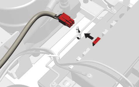
10 Task. Disconnect wires at the WAGO connectors. Leave the WAGO connectors on the wires coming from the trolley. Optional NOTE If the connections were made with red connectors, cut the wires from the coil cable flush with where they enter the connector. Next Step See Cut the Light Cable on the next page Rev B

11 Cut the Light Cable Recommended Tool Diagonal cutters Cut the cable at the ends of the flexarm. A-dec 37 mounted on an A-dec 36 Support Center Shown Rev B
 on page 4. Move the light head to its lowest position.")

12 Place the Flexarm Block NOTE This procedure is not required for track mount systems. If the system is a track mount, go to Uninstall an A-dec 500 or 6300 Light Head (3 Axis) on page 4. Move the light head to its lowest position. Insert the pointed tab (on the notched end of the block) into the flexarm. 3 Insert the shorter tab into the light post. WARNING Failure to install the flexarm block can result in the sudden rise of the flexarm and potential injury. Next Step See the section for the system s configuration: Uninstall an A-dec 300 Light Head ( Axis) on the next page Uninstall an A-dec 500 or 6300 Light Head (3 Axis) on page Rev B


13 Uninstall an A-dec 300 Light Head ( Axis) Recommended Tools /8" and 5/3" hex keys Task. Use a 5/3" hex key to remove the switch housing cover. Task. Fixed Stop Brass Bushing Use a /8" hex key to remove the pin. Remove the head and brass bushing. NOTE Make sure the fixed stop stays installed in the light head knuckle. It will be used with the LED light. Next Step See Remove the Flexarm Block on page Rev B 3
14 Uninstall an A-dec 500 or 6300 Light Head (3 Axis) Recommended Tools 5/3" hex key Needle-nose pliers Task. Remove this side of the switch housing cover. The other side is connected to a strain relief. 6A 5 VAC 3A 50 VAC ON ON ON Rev B
15 Task. Hold the pin. 6A 5 5 VAC VAC 3A VAC VAC ON ON ON ON ON Use a 5/3" hex key to remove the top screw. Task 3. Fixed Stop Remove the pin. Remove the head and brass bushing. Brass Bushing 6A 5 VAC 3A 50 VAC ON ON ON NOTE Make sure the fixed stop stays installed in the light head knuckle. It will be used with the LED light. Next Step See Remove the Flexarm Block on the next page Rev B 5


16 Remove the Flexarm Block NOTE This procedure is not required for track mount systems. If the system is a track mount, go to the next section, Remove the Light Cable. Push the flexarm down and maintain pressure on top. Remove the block. 3 Slowly raise the flexarm. Remove the Light Cable NOTE If the system is a wall/cabinet mount, go to the procedure on the following page. Recommended Tool Pliers A-dec 3 Chair with an A-dec 36 Support Center Shown Remove the pieces of cable. NOTE If the cables are on a light with a Radius -style arm, save the umbilical wrap for the LED installation Rev B


17 Remove the Light Cable from Wall/Cabinet Mount Systems Recommended Tools /6" hex key Masking tape Diagonal cutters Pliers Task. Loosen the setscrew. Slide the collar up. 3 Hold the collar in place with a ring of tape. Task. Support the arm from underneath and remove the key. Slide the flexarm down. 3 Cut the cable. 4 Remove the pieces of cable. NOTE The A-dec 6300 light hub tool is available (p/n ) to hold the flexarm in place while working with the connections Rev B 7


18 Install the LED Light Cable CAUTION Route the light cable so that it sits in the groove at the bottom of the flexarm. If the cable is not in the groove, the cable may get damaged or interfere with the flexarm functionality. You may need to remove the flexarm cover to confirm the cable is properly seated. See the section for instructions on routing the light cable for the system s configuration: A-dec 300 Base Mount Post A-dec 36 Support Center Radius-Style Arm on an A-dec A-dec 500 Support Arm Wall/Cabinet Mount Ceiling Mount Track Mount A-dec NOTE Flexarms on chair mounted lights have a cap where the flexarm meets the rigid arm. Use a 5/64" hex key to remove this cap and make the cable routing easier Rev B
 exposed from the knuckle.")
19 A-dec 300 Base Mount Post Recommended Tool Cable snake When routing the cable, the connector belongs by the light head knuckle. Route the cable from the light head knuckle to the power supply. Leave 6" (5 mm) exposed from the knuckle. 6" (5 mm) Next Step See Install the Light Head on page Rev B 9
 exposed from the knuckle. 6\" (5 mm) Next Step See Install the Light Head on page 30. 0 86.035.")
20 A-dec 36 Support Center Recommended Tool Cable snake A-dec 36 Support Center on an A-dec 3 Chair Shown When routing the cable, the connector belongs by the light head knuckle. Route the cable from the light head knuckle to the support center. Leave 6" (5 mm) exposed from the knuckle. 6" (5 mm) Next Step See Install the Light Head on page Rev B

21 Radius-Style Arm on an A-dec 5 Recommended Tool Cable snake Task. When routing the cable, the connector belongs by the light head knuckle. Route the cable from the light head knuckle through the posts. Leave 6" (5 mm) exposed from the knuckle. 6" (5 mm) Rev B


22 Task. Install the umbilical wrap around the cable. Slide the wrap slightly into the rigid arm. Wrap Task 3. Route the cable. Next Step See Install the Light Head on page Rev B
 exposed from the knuckle. 6\" (5 mm) Next Step See Install the Light Head on page 30.")
23 A-dec 500 Support Arm Recommended Tools Standard screwdriver Cable snake When routing the cable, the connector belongs by the light head knuckle. Route the cable from the light head knuckle to the power supply. Leave 6" (5 mm) exposed from the knuckle. 6" (5 mm) Next Step See Install the Light Head on page Rev B 3
 exposed from the knuckle. 6\" (5 mm) Light Head Knuckle 4 86.035.00 Rev B")
24 Wall/Cabinet Mount Recommended Tools Phillips head screwdriver /6" and 5/64" hex keys Cable snake Task. Remove the flexarm cover. Task. When routing the cable, the connector belongs by the light head knuckle. Route the cable from the light head knuckle to the end that inserts into the trolley post. Leave 6" (5 mm) exposed from the knuckle. 6" (5 mm) Light Head Knuckle Rev B

25 Task 3. Route the light cable to the transformer. Task 4. Slide the flexarm into the post. Insert the key Rev B 5

26 Task 5. Remove the tape. Lower the collar over the slot so that the setscrew is not over the key. Firmly tighten the setscrew. Key Next Step See Install the Light Head on page 30. Ceiling Mount Recommended Tool Cable snake When routing the cable, the connector belongs by the light head knuckle. Route the cable from the light head knuckle to the transformer. Leave 6" (5 mm) exposed from the knuckle. 6" (5 mm) Next Step See Install the Light Head on page Rev B
 exposed from the knuckle. Next Step See Install the Light Head on page 30. 86.035.00 Rev B 7")
27 Track Mount Recommended Tools 5/64" hex key Phillips head screwdriver Cable snake Task. Remove the flexarm cover. Task. Light Head Knuckle 6" (5 mm) When routing the cable, the connector belongs by the light head knuckle. Route the cable from the light head knuckle to the end that inserts into the trolley post. Leave 6" (5 mm) exposed from the knuckle. Next Step See Install the Light Head on page Rev B 7
28 A-dec 00 Recommended Tools Phillips head screwdriver Cable snake Task. Remove the flexarm cover. Task. Align the flexarm directly over the rigid arm. Lift up and remove the flexarm Rev B
 exposed from the knuckle. Task 4. 3 Route the cable through the rigid arm to the support center. Align the flexarm directly over the rigid arm. Insert the flexarm into the rigid arm.")
29 Task 3. Light Head Knuckle 6" (5 mm) When routing the cable, the connector belongs by the light head knuckle. Route the cable from the light head knuckle to the end that inserts into the rigid arm. Leave 6" (5 mm) exposed from the knuckle. Task 4. 3 Route the cable through the rigid arm to the support center. Align the flexarm directly over the rigid arm. Insert the flexarm into the rigid arm. Next Step See Install the Light Head on the next page Rev B 9

30 Install the Light Head Recommended Tools Diagonal cutters 5/64" and 7/64" hex keys Task. Apply Lubriplate to the knuckle. 3 4 Slide the cap above the knuckle. Verify the fixed stop is installed. Slide the white pivot bearing over the knuckle. Make sure the slot is not over the fixed stop. Slot Rev B


31 Task. Rotation Stop Actual Size Keep the slot clear. Insert the rotation stop with its concave side towards the knuckle. Slide the rotation stop in the groove until it does not block the slot. Task 3. Remove the two screws securing the indicator cover. Slide the cover away from the housing to release the keyhole from the post Rev B 3

32 Task 4. Unplug the indicator cover wire Rev B

33 Task 5. Post Align the grooves in the light head with the posts on the pivot bearing and slide the light onto the knuckle Rev B 33


34 Task 6. Insert the locking nut with its loop pointed to the right so that its grooves line up with the posts on the pivot bearing. Task 7. Turn the locking nut a /4 turn until the loop is over the hole for the screw. Use a 7/64" hex key to secure the locking nut with a washer and screw Rev B


35 Task 8. Align the grooves in the brass pressure plate with the posts on the pivot bearing, then slide the plate onto the bearing. Task 9. Align the threads on the friction adjustment collar with the internal thread start. Screw in the friction adjustment until the head moves smoothly and holds its position. CAUTION When starting to install the friction adjustment, carefully align its threads to avoid cross threading Rev B 35

36 Task 0. Start the two screws for the top cap. Once both screws are started, securely tighten them Rev B

37 Task. 3 Connect the black wire to 0 V. Connect the gray wire to 4 V. Connect the data wire. Route the light cable around the three standoffs. CAUTION Make sure to route the light cable sheath, not the exposed wires, around the standoffs. If the exposed wires are routed around the standoffs, they may become damaged. NOTE Do not install the indicator cover yet. You will install the cover after adjusting the rotation tension. 0 V 4 V Rev B 37
38 Connect the Electrical Wires and Data Line See the section for instructions on routing the light cable for the system s configuration: A-dec 300 Base Mount Post A-dec 36 Support Center A-dec A-dec Wall/Cabinet Mount Ceiling Mount Track Mount A-dec Rev B

39 A-dec 300 Base Mount Post. Peel off the protective paper from the adapter board (from the kit). Attach the adapter board to the floor box cover frame. CAUTION Do not attach the adapter board to the top of the power supply chassis. The power supply cover will not fit.. Connect the black wire to 0 V. Connect the gray wire to 4 V. 3. Connect the wires to the positions on the adapter board as labeled; brown to BRN, red to RED, and orange to ORN. 4. Connect the data line jumper from the adapter board to a data port. 0 V 4 V 4 3 Next Step See Test the Light on page Rev B 39
 as labeled; brown to BRN, red to RED, and orange to ORN. 3. Peel off the protective paper from the adapter board.")
40 A-dec 36 Support Center Make the following connections in the support center:. Connect the black and gray wires to their corresponding WAGO connectors.. Connect the wires to the positions on the adapter board (from the kit) as labeled; brown to BRN, red to RED, and orange to ORN. 3. Peel off the protective paper from the adapter board. Attach the adapter board to the support center frame. 4. Connect the data line jumper from the adapter board to a data port. 5. Coil and secure the excess cable Next Step See Test the Light on page Rev B

41 A-dec 5. Peel off the protective paper from the adapter board (from the kit). Attach the adapter board to the front of the power supply in the upper right corner. CAUTION Do not attach the adapter board to the top of the power supply chassis. The pump cover will not fit.. Connect the black jumper wire from the kit to 0 V. Connect the gray jumper wire from the kit to 4 V. 3. Connect the black jumper wire to the black wire from the cable with a WAGO connector. Connect the gray jumper wire to the gray wire from the cable with a WAGO connector. 4. Connect the wires to the positions on the adapter board as labeled; brown to BRN, red to RED, and orange to ORN. 5. Connect the data line jumper from the adapter board to a data port. 6. Secure the cable to the bail with a cable tie. 5 Power Supply 6 0 V 4 V 4 3 Next Step See Test the Light on page Rev B 4

 Cut off the white connector.")
42 A-dec Wall/Cabinet Mount Recommended Tools Phillips head screwdriver Diagonal cutters Task. Remove the relay board. Reinstall the two screws to secure the transformer. Task. 3/8" (0 mm) Cut off the white connector. Strip back the wires 3/8" (0 mm). The wires are 6 AWG Rev B
43 Task 3. Cut the LED light cable so the length reaches the bottom of the transformer housing. Task 4. 3" (76 mm) 3/8" (0 mm) At the cut end of the cable, strip the sheath back 3" (76 mm). Cut the green/yellow wire at the sheath. 3 Strip back the remaining wires 3/8" (0 mm). The black and gray wires are AWG and the brown, red, and orange wires are 6 AWG. CAUTION To strip the sheath, use a proper cable stripping tool and technique to ensure the insulation of the inner conductors is not cut or otherwise compromised Rev B 43


44 Task 5. Cap the yellow, blue, and gray wires from the transformer with wire nuts. NOTE The gray wires do not connect to each other for this configuration. 3 Connect the black wires with a WAGO connector. Connect the gray wire from the light cable to the violet wire from the transformer with a WAGO connector. Task 6. 3 Connect the light wires to the positions on the adapter board (from the kit) as labeled; brown to BRN, red to RED, and orange to ORN. Connect the data line. Peel off the protective paper from the adapter board. Attach the adapter board. Next Step See Test the Light on page Rev B

 Cut off the white connector.")
45 Ceiling Mount Recommended Tools Phillips head screwdriver Diagonal cutters Task. Remove the relay board. Reinstall the two screws to secure the transformer. Task. 3/8" (0 mm) Cut off the white connector. Strip back the wires 3/8" (0 mm). The wires are 6 AWG Rev B 45
. The black and gray wires are AWG and the brown, red, and orange wires are 6 AWG.")
46 Task 3. Cut the LED light cable so its length reaches 4" (0 mm) beyond the transformer housing. 4" (0 mm) Task 4. 3" (76 mm) 3/8" (0 mm) At the cut end of the cable, strip the sheath back 3" (76 mm). Cut the green/yellow wire at the sheath. 3 Strip back the remaining wires 3/8" (0 mm). The black and gray wires are AWG and the brown, red, and orange wires are 6 AWG. CAUTION To strip the sheath, use a proper cable stripping tool and technique to ensure the insulation of the inner conductors is not cut or otherwise compromised Rev B


47 Task 5. Cap the yellow, blue and gray wires from the transformer with wire nuts. NOTE The gray wires do not connect to each other for this configuration. 3 Connect the black wires with a WAGO connector. Connect the gray wire from the light cable to the violet wire from the transformer with a WAGO connector. Task 6. 3 Connect the light wires to the positions on the adapter board (from the kit) as labeled; brown to BRN, red to RED, and orange to ORN. Connect the data line. Peel off the protective paper from the adapter board. Attach the adapter board. Next Step See Test the Light on page Rev B 47
 3/8\" (0 mm) At the cut end of the cable, strip the sheath back 3\" (76 mm). Cut the green/yellow wire at the sheath. 3 Strip back the remaining wires 3/8\" (0 mm).")
48 Track Mount Install the Flexarm Assembly Recommended Tools Diagonal cutters /6" hex key Task. Cut the cable so its length reaches 4" (0 mm) beyond the flexarm knuckle. 4" (0 mm) Task. 3" (76 mm) 3/8" (0 mm) At the cut end of the cable, strip the sheath back 3" (76 mm). Cut the green/yellow wire at the sheath. 3 Strip back the remaining wires 3/8" (0 mm). The black and gray wires are AWG and the brown, red, and orange wires are 6 AWG. CAUTION To strip the sheath, use a proper cable stripping tool and technique to ensure the insulation of the inner conductors is not cut or otherwise compromised Rev B

49 Task 3. To Light Post Violet Gray Black Black Lightly lubricate the hub of the flexarm assembly. Do not lubricate the groove where the key will sit. Yellow Blue Orange Red White Brown Black/White Connect the colored wires in each WAGO connector as shown. To Light Head Rev B 49


50 Task 4. Slide the flexarm into the post. CAUTION Be careful when sliding the flexarm onto the post that the wires and WAGO connectors do not get caught in the key slot. Insert the key. Task 5. Remove the tape. Lower the collar over the slot so that the setscrew is not over the key. Firmly tighten the setscrew. Key Rev B


51 Connect the Wires at the Transformer Recommended Tools 5/64" hex key Phillips head screwdriver Diagonal cutters Task. Remove the transformer cover. Task. Disconnect the wires and data line Rev B 5

.")
52 Task 3. Remove the relay board. Reinstall the two screws to secure the transformer. Task 4. Cut off the white connector. Strip back the wires 3/8" (0 mm). The wires are 6 AWG. 3/8" (0 mm) Rev B

53 Task 5. Cap the gray, blue, and yellow wires from the transformer with wire nuts. Attach a WAGO connector to the black and violet wires that come from the transformer Rev B 53
 as labeled; white to BRN, blue to RED, and yellow to ORN. 4. Connect the data line. 5.")
54 Task 6.. Connect the black and violet wires from the light cable to their corresponding WAGO connectors.. Cap the black/white wire with a wire nut. 3. Connect the remaining light cable wires to the positions on the adapter board (from the kit) as labeled; white to BRN, blue to RED, and yellow to ORN. 4. Connect the data line. 5. Peel off the protective paper from the adapter board. Attach the adapter board Next Step See Test the Light on page Rev B
 as labeled; brown to BRN, red to RED, and orange to ORN. 3. Peel off the protective paper from the adapter board.")
55 A-dec 00 Recommended Tool Phillips head screwdriver Task.. In the support center, connect the black and gray wires to their corresponding WAGO connectors.. Connect the wires to the positions on the adapter board (from the kit) as labeled; brown to BRN, red to RED, and orange to ORN. 3. Peel off the protective paper from the adapter board. Attach the adapter board toward the bottom of the relay board frame. 4. Connect the data line jumper from the adapter board to a data port. 5. Coil and secure the excess cable Rev B 55


56 Task.. Disconnect the data line.. Disconnect the jumper wire. 3. Uninstall the relay board. 4. Replace the screw in the top of the power supply. 3 Task 3. Remove the relay board, data line, and cable. Next Step See Test the Light on the next page Rev B
57 Test the Light Task. Plug in the indicator cover wire Rev B 57


58 Task.. Turn on the system.. Turn on the light. 3. Press the buttons to test the light in each mode. 4. For each mode, verify that the correct light on the indicator cover is illuminated. 5. If it doesn t work properly, check the wire connections. 4 3 Cure-Safe High Medium Low Rev B


59 Adjust the Light Adjust the Horizontal and Diagonal Rotation Tension Recommended Tool 7/64" hex key Task. To adjust horizontal tension, rotate the friction adjustment. Clockwise increases the tension. To adjust diagonal tension, turn the setscrew. Clockwise increases the tension. Task. Slide the indicator cover so the keyhole fits around the post; then use the two screws to secure the cover Rev B 59

60 Adjust the Vertical Tension Recommended Tool 7/64" hex key To adjust the tension, turn the screw. Clockwise increases the tension Rev B

61 Adjust the Dental Light Flexarm Counterbalance Recommended Tools Phillips head screwdriver 5/64" hex key /" combination wrench. If the flexarm cover is in place, remove it.. Adjust the nut on the end of the spring. If the dental light drifts up, turn the nut counterclockwise. If the dental light drifts down, turn the nut clockwise. 3. Set the cover back onto the flexarm (but do not reattach it yet). Check for drift. 4. Repeat steps and 3 until drift is eliminated. NOTE An optional travel stop limit kit (p/n ) can be installed to limit the upward and downward motion of the flexarm Rev B 6

 at the")

62 Touchpad Dental Light Functions Standard Touchpad Turn on the power to the system. To verify the light turns on and off, and toggles between intensity modes, repeatedly press and release. NOTE When the light is in the composite (or cure-safe) mode, the light indicator on the touchpad flashes. 3 To disable the auto on/off feature, press and hold and (or and on the A-dec 300 deluxe touchpad) at the same time for three seconds. One beep indicates that the auto on/off function is off. To re-enable, repeat this step. Three beeps indicate that the auto on/off feature is activated. A-dec 300 Deluxe Touchpad A-dec 500 Deluxe Touchpad Rev B
63 Rev B 63
64 Regulatory Information Regulatory information mandated by agency requirements is provided in the Regulatory Information, Specifications, and Warranty document (p/n ), which is available in the Document Library at A-dec Headquarters 60 Crestview Drive Newberg, OR 973 USA Tel: Within USA/Canada Tel: Outside USA/Canada Fax: / A-dec Inc. makes no warranty of any kind with regard to the content in this document including, but not limited to, the implied warranties of merchantability and fitness for a particular purpose. ÍvÈ.Ç#9È.00RÎ Rev B Copyright 05 A-dec Inc. All rights reserved. IGgrphpor
A-dec 584 Monitor Mount on a Central Cabinet
 Installation Guide A-dec 584 Monitor Mount on a Central Cabinet Before You Begin This procedure applies to the A-dec Inspire TM 592 Central Console and the standard and tall Preference cabinet central
A-dec 586 Ceiling Monitor Mount
 Installation Guide A-dec 586 Ceiling Monitor Mount Recommended Tools 7/16" wrench Socket set and ratchet with 6" extension Phillips head and standard screwdrivers Diagonal cutters Level 3/8" drill with
Installation Guide. Retrofit Kit for USB Ready Intraoral Systems
 Installation Guide Retrofit Kit for USB Ready Intraoral Systems Table of Contents Wall-Mount Retrofit Kit... 2 Introduction... 2 Connecting the Articulating and Horizontal Arm Cables... 2 Installing the
Installing a Power over Ethernet injector
 Installing a Power over Ethernet injector AlphaEclipse StreetSmart and RoadStar signs The instructions in this document explain how to install/replace a Power over Ethernet (PoE) injector in a StreetSmart
G12/G12x USER S MANUAL
 G12/G12x USER S MANUAL TABLE OF CONTENTS SECTION 1 SLIDE CONFIGURATION SECTION 2 SLIDE CONFIGURATION ACCESSORIES SECTION 3 TABLETOP CONFIGURATION SECTION 4 TABLETOP CONFIGURATION ACCESSORIES SECTION 5
TABLE OF CONTENTS SECTION 1 TABLETOP CONFIGURATION SECTION 2 TABLETOP CONFIGURATION ACCESSORIES SECTION 3 SLIDE CONFIGURATION
 S6 USER S MANUAL TABLE OF CONTENTS SECTION 1 TABLETOP CONFIGURATION SECTION 2 TABLETOP CONFIGURATION ACCESSORIES SECTION 3 SLIDE CONFIGURATION SECTION 4 SLIDE CONFIGURATION ACCESSORIES SECTION 5 RACK MOUNT
E1135C PDU and Pod Upgrade Procedure
 E4030-90010 Rev. B 12/2003 In this Document... Tools Needed, 2 Contents of the Upgrade Kits, 2 Installation Procedures, 4 Verifying the Power Option of the New PDU, 4 Removing the PDU from the Support
A-dec Dental Lights and Monitor Mounts Service Reference
 A-dec Dental Lights and Monitor Mounts Service Reference Copyright Contact Information and Other Resources Contents 01 A-dec Inc. All rights reserved. A-dec Inc. makes no warranty of any kind with regard
TRC-190 User s Manual
 First Edition, November 2008 www.moxa.com/product 2008 Moxa Inc. All rights reserved. Reproduction without permission is prohibited. The software described in this manual is furnished under a license agreement
Upgrade Instructions. P/N Revision A. October Printer Terminal Holder * *
 Upgrade Instructions P/N 96-08-0 Revision A October 000 480 Printer Terminal Holder P/N 96-08-0 Revision A *96080* Instructions This terminal holder connects the INTERMEC R 600 Series and 700 Series Computers
Cutter Option Installation Instructions
 This kit includes the parts and documentation necessary to install the cutter option on the Zebra XiII, XiIII, and XiIIIPlus-Series printers. NOTE: The Cutter Option is not available for the 96XiIII. Adding
TDM To MiniMech conversion ProceDure
 TDM To MiniMech conversion ProceDure (Model 9100 ATM) TDN 07102-00079 Apr 1 2009 CorporATe HeAdquArTers: 522 E. Railroad Street Long Beach, MS 39560 PHONE: (228) 868-1317 FAX: (228) 868-0437 COPYRIGHT
Replacing the PanelMate Power Pro 1785 Series, PanelMate epro 7585x-8 and 7685x-8 Series Backlight Assembly
 Replacing the PanelMate Power Pro 1785 Series, PanelMate epro 7585x-8 and 7685x-8 Series Assembly Introduction The Replacement Kit provides a replacement backlight for the PanelMate Power Pro 1785 Series,
TRC-190 User s Manual
 User s Manual Edition 3.2, May 2017 www.moxa.com/product 2017 Moxa Inc. All rights reserved. User s Manual The software described in this manual is furnished under a license agreement and may be used only
Removal and Installation8
 8 Screw Types 8-4 Top Cover Assembly 8-5 Left Hand Cover 8-6 Right Hand Cover 8-10 Front Panel Assembly 8-14 Left Rear Cover 8-15 Right Rear Cover 8-16 Extension Cover (60" Model only) 8-17 Media Lever
1. Mount the echo and tremolo control switches under the keyboard shelf, in a position convenient for the organist.
 CONSOLE CONNECTOR KIT 8101 INSTALLATION INSTRUCTIONS FOR USE WITH: HAMMOND Organ Models A-100, D-100, RT2, RT3 LESLIE Speaker Models 122, 122RV KIT CONTENT Console Connector Assembly 047357 Echo Control
Replacing the Power Supply
 APPENDIX B This appendix includes information on how to replace the power supply for the Cisco AS550XM universal gateway and contains the following sections: Safety Recommendations, page B-1 Required Tools
LED Maintenance Instructions
 Chapter 5 LED Maintenance Instructions This guide describes the maintenance procedures for the LED portion of your DayStar or TekStar sign. 1.800.237.3928 stewartsigns.com Rev1802 Intentionally Left Blank
Megatouch FORCE Monitor Chassis Board Replacement
 Megatouch FORCE Monitor Chassis Board Replacement Visit the Merit Industries, Inc. Web site http://www.meritind.com merit industries, inc. PM0337-01 Rev C Table of Contents FORCE Classic Monitor Chassis
JLTX Lever and Joystick Replacement Instructions
 JLTX Lever and Joystick Replacement Instructions WARNING THE INCORRECT INSTALLATION OF A LEVER OR JOYSTICK CAN CAUSE AN EQUIPMENT MALFUNCTION FAILURE TO FOLLOW THIS PROCEDURE CAREFULLY COULD RESULT IN
To connect the AC adapter:
 Replacing the AC Adapter Replacing the AC Adapter 3 Plug the power cord into a wall outlet. The power indicator turns on. To connect the AC adapter: Connect the power cord to the AC adapter. Power indicator
Installing and Removing SDRAM and DRAM
 CHAPTER 4 This chapter explains how to remove and replace the main memory modules on the network processing engine or network services engine. For the location of the memory module you are replacing, find
ATTENTION: OBSERVE PRECAUTIONS FOR HANDLING ESD-SENSITIVE DEVICES
 15 Monitor Removal 1. Turn off and unplug the game. 2. Place something in front of the game to brace the bezel once the strain relief cord is undone, then unlock and open the CPU section. 3. Remove the
Series 3700 Screw Terminal Assemblies Installation Instructions
 Keithley Instruments, Inc. 28775 Aurora Road Cleveland, Ohio 44139 1-888-KEITHLEY www.keithley.com Series 3700 Screw Terminal Assemblies Installation Instructions Introduction This document contains handling
ColorMaxLP Label Roll Rewinder
 ColorMaxLP Label Roll Rewinder 5/2017 INSTALLATION/OPERATOR MANUAL Included: Rewinder Base plate Power supply Power Cord Thumb screws Assembly instructions 1. Install base plate Lift front of printer and
CINTENNA ANTENNA REPAIR GUIDE
 The Cintenna is a great tool when looking to transmit WIRELESS DMX data over obstacles or hard to reach places. Wireless DMX can have its issues when not having a good line of sight between the transmitter
PowerFlex 400 Frame G and H Replacement Procedure for Gate Power Board
 Service Bulletin PowerFlex 400 Frame G and H Replacement Procedure for Gate Power Board Contents This publication provides instructions for replacing the gate power board for PowerFlex 400 Frame G and
Peel/Rewind Upgrade Kit
 Peel/Rewind Upgrade Kit Installation Instructions This kit includes the parts and documentation necessary to install the Peel/Rewind upgrade kit on the following printers: ZM400 ZM600 Read these instructions
edrive RAM Battery Alternate Replacement Procedure
 edrive RAM Battery Summary This technical note describes the process for replacing the TINI RAM battery with a higher capacity battery. With the edrive turned on, the external battery can be changed without
Phase Loss Protection Upgrade. Phase Loss Protection Upgrade. In this bulletin:
 Phase Loss Protection Upgrade In this bulletin: Introduction... 2 Purpose... 2 General... 2 Applicability... 2 HD3070 Phase Loss Protection Upgrade Kit Parts... 2 Preparation... 4 Install the Phase Loss
JAN 16 Rev B
 ANSI C136.41-2013 Rotatable Dimming Receptacles Application Specification 20 JAN 16 Rev B NOTE All numerical values are in metric units [with U.S. customary units in brackets]. Dimensions are in millimeters
T9 EPP KEYPAD FIELD UPGRADE
 T9 EPP KEYPAD FIELD UPGRADE TDN 07103-00237 July 1, 2014 Corporate Headquarters 21405 B Street Long Beach, MS 39560 Phone: (800) 259-6672 Fax: (228) 868-9445 COPYRIGHT NOTICE 2014 Triton. All Rights Reserved.
Gateway Profile 4 service guide
 Gateway Profile 4 service guide Customizing Troubleshooting Contents Replacing Components in Your Gateway Profile 4.................. 1 About this guide.....................................................
CARD PRINTER PRINTHEAD REPLACEMENT INSTRUCTIONS
 CARD PRINTER PRINTHEAD REPLACEMENT INSTRUCTIONS CAUTION: The discharge of electrostatic energy that accumulates on the surface of the human body or other surfaces can damage or destroy the printhead. Please
Operating Instructions
 Operating Instructions Model Numbers: LS LS M LS G LS A LS LS 00 LS M-WC LS A LS X LS M-WC LS B LS X LS M LS Dimensions A / B / C / D / E 0 / F / Electrical Information Voltage AMPS Frequency 0 HZ Single
PowerFlex DC Drive - Frame A Switching Power Supply Circuit Board
 Installation Instructions PowerFlex DC Drive - Frame A Switching Power Supply Circuit Board ATTENTION: Only qualified personnel familiar with DC drives and associated machinery should plan or implement
PoE/FPR Kit for Auto-Sync Time Clock. The Auto-Sync Time Clock is a validated time system with a Web interface and auto discovery.
 ASTCPOEK PoE/FPR Kit for Auto-Sync Time Clock The Auto-Sync Time Clock is a validated time system with a Web interface and auto discovery. The ASTCPOEK Kit provides Power over Ethernet with Full Power
Service Bulletin. MiTek. RoofTracker Roof Truss Roller Press. Machinery Affected: Adding an Operator Platform. Machinery Division
 MiTek Machinery Division Service Bulletin Machinery Affected: Document: Title: Applies To: RoofTracker Roof Truss Roller Press SB171 Adding an Operator Platform Frames 51 and Lower Copyright 2006 MiTek.
XDBKITS5 Bus / DB Terminal Kit (Size 5) Installation Manual DPD00116
 Installation Manual DPD00116") XDBKITS5 Bus / DB Terminal Kit (Size 5) Installation Manual DPD00116 XDBKITS5 Option Kit Installation Manual vacon 3 Installing the Bus / DB Terminal Option Kit Introduction The XDBKITS5 option kit is
XDBKITS5 Bus / DB Terminal Kit (Size 5) Installation Manual DPD00116 XDBKITS5 Option Kit Installation Manual vacon 3 Installing the Bus / DB Terminal Option Kit Introduction The XDBKITS5 option kit is
Z-Truck (Vertical Moving) Z-truck Flag. Y-Truck (Horizontal Moving) FIGURE 1: VIEW OF THE Z-TRUCK. Flexshaft Assembly
 Z-truck Flag. Y-Truck (Horizontal Moving) FIGURE 1: VIEW OF THE Z-TRUCK. Flexshaft Assembly") Replacing the LCD Cable To remove and replace the LCD Cable you will need the following tools: #2 Phillips screwdriver (magnetic tip preferred) Socket wrench with 10mm socket Removing the Side Panel 1.
Replacing the LCD Cable To remove and replace the LCD Cable you will need the following tools: #2 Phillips screwdriver (magnetic tip preferred) Socket wrench with 10mm socket Removing the Side Panel 1.
ibook G3 14" Top Shield Replacement
 Written By: irobot ifixit CC BY-NC-SA www.ifixit.com Page 1 of 18 INTRODUCTION The metallic top shield protects the logic board from electromagnetic interference. TOOLS: Coin (1) Paper Clip (1) Phillips
Removal and Installation 8
 Removal and Installation 8 8 Introduction 8-2 Service Calibration Guide to Removal and Installation 8-4 Window 8-8 Covers and Trims 8-12 Rear Tray 8-31 Rear Cover 8-32 Media Lever 8-33 Media Lever Position
Removing and Replacing Parts
 Removing and Replacing Parts Preparing to Work Inside the Computer Recommended Tools Screw Identification System Components Hard Drive Fixed Optical Drive Media Bay Devices Memory Modules Mini PCI Card
PowerFlex DC Drive - Frame A SCR Modules for Drives with a Power Traces Circuit Board
 Installation Instructions PowerFlex DC Drive - Frame A SCR Modules for Drives with a Power Traces Circuit Board!!! ATTENTION: Only qualified personnel familiar with DC drives and associated machinery should
CAMERA ASSEMBLY. Removal/Replacement of the Camera Box Assembly APR-CA. Install Camera Assembly. Remove Camera Assembly
 CAMERA ASSEMBLY Removal/Replacement of the Camera Box Assembly APR-CA REQUIRED TOOLS: 9/64 hex key Small flat-tip screwdriver Remove Camera Assembly camera 1. Locate the camera assembly underneath the
GPIB-232CT-A IBCL EPROM Installation Guide
 NATIONAL INSTRUMENTS The Software is the Instrument Installation Guide GPIB-232CT-A IBCL EPROM Installation Guide This guide describes how to replace the factory-installed EPROM that comes with your GPIB-232CT-A.
Rack Installation Instructions
 Rack Installation Instructions For System Storage EXP2512 and EXP2524 Express Storage Enclosures Use the instructions in this document to install an IBM System Storage EXP2512 Express Storage Enclosure
Nikon Focus Drive Manual
 Nikon Focus Drive Manual PRIOR SCIENTIFIC INC., 80 RESERVOIR PARK DRIVE, ROCKLAND, MA 02370-1062 TELEPHONE 781-878-8442 FAX 781-878-8736 WWW.PRIOR.COM Table of Contents Safety Information...1 Unpacking
imac Intel 27" EMC 2639 Hard Drive
 imac Intel 27" EMC 2639 Hard Drive Replacement Replace the Hard Drive in your imac Intel 27" EMC 2639. Written By: Walter Galan ifixit CC BY-NC-SA www.ifixit.com Page 1 of 26 INTRODUCTION Replacing the
LARGE S URGE-PROTECTOR S HELTER
 LARGE S URGE-PROTECTOR S HELTER The weather-resistant Large Surge-Protector Shelter (simply referred to as the shelter in this manual) provides protection from the elements for Surge Protectors (not included)
Intel NUC Kit NUC8i7HNK & NUC8i7HVK User Guide. Intel NUC Kit NUC8i7HNK Intel NUC Kit NUC8i7HVK User Guide
 Intel NUC Kit NUC8i7HNK Intel NUC Kit NUC8i7HVK User Guide 1 Before You Begin CAUTIONS The procedures in this user guide assume familiarity with the general terminology associated with personal computers
System Storage EXP3000 Rack Installation Instructions
 System Storage EXP3000 Rack Installation Instructions Review the documentation that comes with your rack cabinet for safety and cabling information. When you install the IBM System Storage EXP3000 in a
ibook G3 14" Hard Drive Replacement
 Written By: irobot ifixit CC BY-NC-SA www.ifixit.com Page 1 of 20 INTRODUCTION How to remove the hard drive and its bracket from your computer. TOOLS: Coin (1) Paper Clip (1) Phillips #00 Screwdriver (1)
H3C S12500 Routing Switch Series
 H3C S12500 Routing Switch Series Quick Installation Guide Hangzhou H3C Technologies Co., Ltd. http://www.h3c.com Document version: APW201-20131030 Copyright 2013, Hangzhou H3C Technologies Co., Ltd. and
INSTALLATION INSTRUCTIONS
 CONSOLE CONNECTOR KIT 7830 FOR USE WITH: LESLIE Speaker Model 130 Various single and double channel organs INSTALLATION INSTRUCTIONS KIT CONTENT Console Connector 137283 Switch Assembly, Cable Assembly,
7403 K321. Display Wall Mount. Kit Instructions. Issue A
 7403 K321 Display Wall Mount Kit Instructions Issue A ii Revision Record Issue Date Remarks A Nov 2008 First issue 1 Introduction This kit is used in to secure a 7403 Display Head on a vertical surface.
Print Mechanism Maintenance Kit
 Print Mechanism Maintenance Kit Installation Instructions This kit includes the parts and documentation necessary to install the print mechanism maintenance kit in the following printers: ZT0 ZT0 ZT0 Read
LED Lighting Kit For Elara NanoEdge Fixed Frame. Installation Guide. Attention: Read this guide before assembling your screen.
 LED Lighting Kit For Elara NanoEdge Fixed Frame Installation Guide Attention: Read this guide before assembling your screen. INTRODUCTION GETTING STARTED WARNING - Sharp Edges This product may contain
Description: Detailed procedure on removing old bushing and installing new Brake Bushing Replacement Kit 10447
 Procedure: BRAKE BUSHING REPLACEMENT PROCEDURE Product: Document #: Rev: Page: MODEL 7000, 7000A, & 8000 GYRO 078 1 1 of 14 Description: Detailed procedure on removing old bushing and installing new Brake
Control Box Setup - PRSalpha
 888-680-4466 ShopBotTools.com Control Box Setup - PRSalpha Copyright 2016 ShopBot Tools, Inc. page 1 Copyright 2016 ShopBot Tools, Inc. page 2 Parts List: Hooking Up a PRSalpha Gantry Tool Powering the
Replacement Instructions
 imac G5 Inverter, 20-inch Replacement Instructions Follow the instructions in this document carefully. Failure to follow these instructions could damage your equipment and void its warranty. Note: Online
CONEC Industrial Ethernet Circular Sealed RJ45 Connector System consists of a RJ45 Plug Kit, a Receptacle Kit and a Protective Cover Assembly.
 Revised Sept-28-2009 Sealed Industrial Ethernet Circular IP67 Cat. 5e RJ45 Connector System Instructions CONEC Industrial Ethernet Circular Sealed RJ45 Connector System consists of a RJ45 Plug Kit, a Kit
Rack Installation Instructions
 Rack Installation Instructions Review the documentation that comes with your rack cabinet for safety and cabling information. When installing your server in a rack cabinet, consider the following: v Two
Upgrading LVDS Cables Instruction Sheet
 Upgrading LVDS Cables Instruction Sheet INTRODUCTION Use the following instructions to replace the LVDS cables in CP2000-M/MR projectors. The new cables are slightly longer in length and allow for better
Raven Adapter Harness
 Note: Indented items indicate parts included in an assembly listed above Quantity by System Part Name/Description Part Number With Switch Box With Built-in Switches Raven Harness Adapter Kit 4100504 1
E2460GS Oscilloscope Upgrade Kit
 Installation Instructions for E2460GS Oscilloscope Upgrade Kit Agilent 1670G-Series Logic Analyzers This kit upgrades either the Agilent Technologies 1670G, Agilent 1671G, Agilent 1672G, or the Agilent
In-Sight 7000 Series Vision System. Optional Configurations
 In-Sight 7000 Series Vision System Optional Configurations Legal Notices The software described in this document is furnished under license, and may be used or copied only in accordance with the terms
imac Intel 21.5" EMC 2389 Stand Replacement
 imac Intel 21.5" EMC 2389 Stand Replacement Replace a broken or cosmetically unappealing stand on the imac 2389 21.5 Written By: Aaron Cooke ifixit CC BY-NC-SA www.ifixit.com Page 1 of 30 INTRODUCTION
V5420 Host Card Upgrade Kit for R3082D Quick Start Guide
 Quick Start Guide Upgrade kit contents The table below shows the contents of the V5420 Host Card Upgrade Kit (components are not shown to scale). Part Function Pieces V5420 Host Card 1 Host card bracket
Zebra XiII-Series Printer Quick Reference Guide
 Zebra XiII-Series Printer Quick Reference Guide Contents Media and Ribbon Loading...67 Media Loading...67 Ribbon Loading...70 Operator Controls...72 Front Panel Keys...72 Front Panel Lights...72 Calibration...74
Installing 6 Indexer: PRS Standard Tools
 888-680-4466 ShopBotTools.com Installing 6 Indexer: PRS Standard Tools Copyright 2016 ShopBot Tools, Inc. page 1 Copyright 2016 ShopBot Tools, Inc. page 2 Table of Contents Overview...5 Installing the
Cone Beam Volumetric Tomography and Panoramic Dental Imaging System
 Installation Manual Installation Manual Installation Manual Installation Manual Installation Manual Cone Beam Volumetric Tomography and Panoramic Dental Imaging System Gendex CB-500 Installation Manual
PRODUCT MARKING AND BARCODE IDENTIFICATION. up to Serial No Barcode/Label printer MACH4. Service Manual. Edition 11/06
 PRODUCT MARKING AND BARCODE IDENTIFICATION up to Serial No. 9999 Barcode/Label printer MACH4 Service Manual Edition 11/06 copyright by cab / 9008553 / Q49 / 1 All specifications about delivery, design,
*E * E E0606
 75000 SERIES B Instrument BASIC Installation Note Copyright Agilent Technologies, Inc., 1990-2006 *E1300-90020* E1300-90020 E0606 Manual Part Number: E1300-90020 Printed: June 2006 Edition 1 Rev 2 Microfiche
AF Upgrade Instructions
 8602 8631AF Upgrade Instructions Bering Technology, Inc. 1400 Dell Avenue, Suite B Campbell CA 95008-6620 (408) 364-6500 FAX: (408) 364-6501 Email: info@bering.com Contents 15-18631-81 Revision D This
Intel NUC Kit NUC8i7HNK & NUC8i7HVK User Guide. Intel NUC Kit NUC8i7HNK Intel NUC Kit NUC8i7HVK. User Guide
 Intel NUC Kit NUC8i7HNK Intel NUC Kit NUC8i7HVK User Guide 1 Before You Begin CAUTIONS The procedures in this user guide assume familiarity with the general terminology associated with personal computers
apple Service Source ibook G4 (14.1 LCD) October 22, Apple Computer, Inc. All rights reserved.
 October 22, Apple Computer, Inc. All rights reserved.") apple Service Source ibook G4 (14.1 LCD) October 22, 2003 2003 Apple Computer, Inc. All rights reserved. apple Service Source Take Apart ibook G4 (14.1 LCD) 2003 Apple Computer, Inc. All rights reserved.
apple Service Source ibook G4 (14.1 LCD) October 22, 2003 2003 Apple Computer, Inc. All rights reserved. apple Service Source Take Apart ibook G4 (14.1 LCD) 2003 Apple Computer, Inc. All rights reserved.
DIGITAL OBSERVATION GUARD LOW PROFILE PAN TILT KIT USER MANUAL
 DIGITAL OBSERVATION GUARD LOW PROFILE PAN TILT KIT USER MANUAL Version 2.1 June 4, 2013 0 Table of Contents Low Profile Pan Tilt Kit Description... 3 Low Profile Pan Tilt Unit Basic Operation... 4 Mounting
Zebra XiIII-Series Printer Safety and Quick Reference Guide
 Zebra XiIII-Series Printer Safety and Quick Reference Guide GB Contents Specifications...75 Electrical...75 Environmental Range...75 Fuses...75 Warnings...76 Installation...76 Use of Shielded Data Cables...76
PowerFlex DC Drive Frame B Pulse Transformer Circuit Board
 Installation Instructions PowerFlex DC Drive Frame B Pulse Transformer Circuit Board ATTENTION: Only qualified personnel familiar with DC drives and associated machinery should plan or implement the installation,
How to add a Second Drive to a Mac mini (2012) using the OWC Data Doubler SSD/2.5 Installation Kit
 using the OWC Data Doubler SSD/2.5 Installation Kit") Instructional Video Series How to add a Second Drive to a Mac mini (2012) using the OWC Data Doubler SSD/2.5 Installation Kit Skill Level: Challenging Time to Complete: Approximately 45 Minutes Required
Instructional Video Series How to add a Second Drive to a Mac mini (2012) using the OWC Data Doubler SSD/2.5 Installation Kit Skill Level: Challenging Time to Complete: Approximately 45 Minutes Required
Heat Containment System (HCS)
") Heat Containment System (HCS) Revision Number 1 Wright Line LLC 160 Gold Star Boulevard Worcester, MA 01606 Tel: 800-225-7348 508-852-4300 Fax: 508-365-6178 www.wrightline.com info@wrightline.com All products
Heat Containment System (HCS) Revision Number 1 Wright Line LLC 160 Gold Star Boulevard Worcester, MA 01606 Tel: 800-225-7348 508-852-4300 Fax: 508-365-6178 www.wrightline.com info@wrightline.com All products
imac Intel 27" Retina 5K Display CPU Replacement
 imac Intel 27" Retina 5K Display CPU Replacement Replace or upgrade the CPU in your imac Intel 27" Retina 5K Display. Written By: Sam Lionheart ifixit CC BY-NC-SA www.ifixit.com Page 1 of 36 INTRODUCTION
Serial ATA Hot Swap Drive Cage Upgrade Kit for: Intel Server Chassis SC5200 Intel Server Chassis SC5250-E
 Serial ATA Hot Swap Drive Cage Upgrade Kit for: Intel Server Chassis SC5200 Intel Server Chassis SC5250-E A Guide for Technically Qualified Assemblers of Intel Identified Subassemblies/Products Order Number:
13 MMC for PC Option Modules
 Part Number M.1300.8684 MMC for PC Option Modules Manual V3.0 The information in this document is also available in the MMC for PC Hardware Manual. 13 MMC for PC Option Modules 13.1 General The MMC for
A note about our online installation instructions:
 A note about our online installation instructions: Most Modern Fan Co. products have been in our assortment for several years or longer. As we continually work to improve product performance and user experience,
PowerFlex DC Stand-Alone Regulator (SAR) Field Circuit Board
 Field Circuit Board") Installation Instructions PowerFlex DC Stand-Alone Regulator (SAR) Field Circuit Board ATTENTION: Only qualified personnel familiar with DC drives and associated machinery should plan or implement the
Installation Instructions PowerFlex DC Stand-Alone Regulator (SAR) Field Circuit Board ATTENTION: Only qualified personnel familiar with DC drives and associated machinery should plan or implement the
Rear Consumer LCD Hinge Assembly Large Displays
 7403-K454 Rear Consumer LCD Hinge Assembly Large Displays Kit Instructions Issue D Revision Record Issue Date Remarks A Nov 2008 First issue B June 2009 Removed Power Cable from the kit contents C May
IBM. Rack Installation Instructions
 IBM Rack Installation Instructions Review the documentation that comes with your rack cabinet for safety and cabling information. When installing your server in a rack cabinet, consider the following:
ABM International, Inc. Lightning Stitch Checklist 9/13/2013
 ABM International, Inc. Lightning Stitch Checklist 9/13/2013 1) Piggy backed board assembly (1) Piggy back board assembly tested? Yes No 24v passed XB passed XA passed YB passed YA passed SAFE passed S/S
Replacing the RAID Battery Backup Unit Assembly on Series 3 FireSIGHT 3500 Defense Centers, Version 5.x
 Replacing the RAID Battery Backup Unit Assembly on Series 3 FireSIGHT 3500 Defense Centers, Version 5.x Last Updated: December 4, 2014 Use these instructions to replace the RAID battery backup unit (BBU)
Tile Plow Installation O Connell
 NOTE: Indented items indicate parts included in an assembly listed above Part Name/Description Part Number Quantity Tile Plow Kit O Connell System 4100471 1 Hex head cap screw 3/8-16 x 3 2002003-38300
COMFORT CONTROL CENTER SERVICE INSTRUCTIONS
 USA SERVICE OFFICE Dometic Corporation 2320 Industrial Parkway Elkhart, IN 46516 574-294-2511 CANADA Dometic Corporation 46 Zatonski, Unit 3 Brantford, ON N3T 5L8 CANADA 519-720-9578 For Service Center
User s Guide. Mobile Rack Device Mounting Kit for Echo Express III-R and xmac Pro Server. Quick Start Guide Video Available Online!
 User s Guide Mobile Rack Device Mounting Kit for Echo Express III-R and xmac Pro Server Quick Start Guide Video Available Online! Visit http://www.sonnettech.com/product/ mobilerackkit.html Click the Video
Mac Mini Mid 2011 SSD Dual Drive Installation
 Mac Mini Mid 2011 SSD Dual Drive Installation Install a second hard drive in your mid 2011 Mac Mini. Written By: Dozuki System 2017 guides.crucial.com Page 1 of 19 INTRODUCTION Use this guide to install
SMART Multisensory Fitness Training. Technical Service Manual For the SMART Trainer Systems Revision 1.5.2
 SMART Multisensory Fitness Training Technical Service Manual For the SMART Trainer Systems Revision 1.5.2 2014 Unlike other fitness equipment which may require additional insurance, SMART ProTrainer and
Preparing for a Docking Drawer Slim Installation To prepare for a successful Docking Drawer Slim installation please ensure that the cable management
 Docking Drawer Install Manual Docking Drawer Slim Series Applicable Models: 0290 00031(W) / 24 0290-00030(W) / 21 0290-00047(W) / 18 0230-00004. r6 1/19/2016 CAUTION READ CAREFULLY Failure to follow these
Replacement Keyswitch Assembly
 Installation Instructions Replacement Keyswitch Assembly (Catalog No. 2711E-NKSW1) Applicable Terminals Use this replacement keyswitch with PanelView Terminals 2711-KA1, -KC1, -TA1, -TC1, -TA4, -TC4 and
Microprocessor Module Replacement Kit for Multi-Zone Leak Monitors Instruction Manual
 621 Hunt Valley Circle New Kensington, PA 15068 3015-5547 Tel: 724-334-5000 Revision 4 Fax: 724-334-5001 May 17, 2013 Microprocessor Module Replacement Kit for Multi-Zone Leak Monitors Instruction Manual
Single cable kit for the FCB1010
 Single cable kit for the FCB1010 1. What is it? With this kit, you can turn your FCB1010 into a phantom powered floorboard, which can do 2-way MIDI communication over one single cable. After installing