Please read all of the installation instructions carefully before installing the product. Improper installation will void manufacturer s warranty.
|
|
|
- Kelley Sanders
- 5 years ago
- Views:
Transcription
1 TM 1

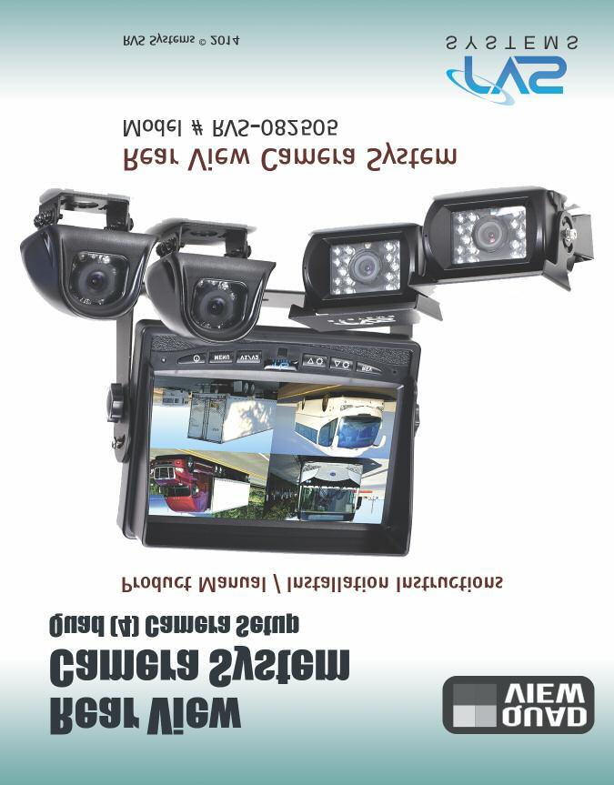
2 What s in the Box? 2 Color CCD Weather Proof Side Cameras w/infra-red 2 Color CCD Weather Proof Backup Cameras w/infra-red 1 DIGITAL 7" TFT LCD Quad View Color Monitor with universal mount/stand and wire 2 66' Extension Cables for Backup Cameras 2 33' Extension Cables for Side Cameras 1 Remote Control 1 Power Connection Wire 1 Screw Kit for installation
3 Table of Contents Introduction...4 Safety Information Before Beginning Installation...8 Installation Guide Installing the Monitor...11 Installation Diagram...12 Monitor Operation...13 Splitting & Splicing...14 Positioning Power Harness...16 Troubleshooting...17 Monitor Dimensions...18 Monitor Specifications...19 Camera Dimensions...20 Camera Specifications...21 Camera Dimensions...22 Camera Specifications...23 Warranty...24 Disclaimer
4 Introduction Please read all of the installation instructions carefully before installing the product. Improper installation will void manufacturer s warranty. Congratulations on purchasing a Rear View Backup Camera System! With this manual you will be able to properly install and operate the unit. The Backup Camera System is intended to be installed as a supplement aid to your standard rear view mirror that already exists in your vehicle. The Backup Camera System should not be used as a substitute for the standard rear view mirror or for any other mirror that exists in your vehicle. In some jurisdictions, it is unlawful for a person to drive a motor vehicle equipped with a TV viewer or screen located forward of the back of the driver s seat or in any location that is visible, directly or indirectly, to the driver while operating the vehicle. 4 RVS Systems
5 Safety Information Please read the entire manual and follow the instructions and warnings carefully. Failure to do so can cause serious damage and/or injury, including loss of life. Be sure to obey all applicable local traffic and motor vehicle regulations as it pertains to this product. Improper installation will void manufacturer s warranty. USAGE The Rear View Camera System is designed to help the driver safely detect people and/or objects helping to avoid damage or injury. However, you the driver, must use it properly. Use of this system is not a substitute for safe, proper or legal driving. Never back up while looking at the monitor alone. You should always check behind and around the vehicle when backing up, in the same way as you would if the vehicle did not have the Rear View Reverse With Confidence Camera System. If you back up while looking only at the monitor, you may cause damage or injury. Always back up slowly. The Rear View Camera System is not intended for use during exstensive back-up maneuvers or backing into cross traffic or pedestrian walkways. Please, always remember, the area displayed by the Rear View Camera System is limited. It does not display the entire panorama that is behind you. 5
6 Safety Information INSTALLATION Electric shock or product malfunction may occur if this product is installed incorrectly. Use this product within the voltage range specified. Failure to do so can cause electronic shock or product malfunction. Take special care when cleaning the monitor. Make sure to firmly affix the product before use. If smoke or a burning smell is detected, disconnect the system immediately. Where the power cable may touch a metal case, cover the cable with a friction tape. A short circuit or disconnected wire may cause a fire. 6 While installing the RVS System be careful with the wire positioning in order to avoid wire damage. The RVS System should only be used when the vehicle is in reverse. Do not watch movies or operate the monitor while driving; as it may cause an accident. Do not install the monitor where it may obstruct drivers view or obstruct an air bag device. Dropping the unit may cause possible mechanical failure. RVS SYSTEMS
7 Safety Information If you have questions about this product, contact: Customer Service: RVS Systems 1797 Atlantic Avenue Brooklyn, NY Tel: IN NO EVENT SHALL SELLER OR MANUFACTURER BE LIABLE FOR ANY DIRECT OR CONSEQUENTIAL DAMAGES OF ANY NATURE, OR LOSSES OR EXPENSES RESULTING FROM ANY DEFECTIVE PRODUCT OR THE USE OF ANY PRODUCT. Reverse With Confidence 7
8 Before Beginning Installation Before drilling please check that no cable or wiring is on the other side of the wall. Please clamp all wires securely to reduce the possibility of them being damaged while vehicle is in use. Keep all cables away from hot or moving parts and electrical noisy components. We recommend doing a benchmark test before installation to insure that all components are working properly. Step 1: Choose the monitor and camera locations. Step 2: Install all cables in vehicle, when necessary a 0.8 (20mm) hole should be drilled for passing camera cable through vehicles walls. Install split grommets where applicable. Step 3: Once all cables and wiring have been properly routed, perform a system function test by temporarily connecting the system. If the system seems to not be operating properly see troubleshooting (page 17). 8 RVS Systems
9 Installation Guide Camera Installation 1. Attach camera bracket close to rear marker lights, centered on vehicle. 2. Camera: Drill a 20mm (0.8in) diameter hole into vehicle body near the camera and bracket. Insert camera cable into vehicle (be careful not to kink cable) and fit grommet into hole. Apply sealant around grommet to increase resistance to water penetration. Connect camera to the camera extension cable which runs inside the vehicle. 3. Feed as much cable as possible into vehicle & clamp securely. This reduces the possibility of cable being hooked or snagged. The aviation camera cable uses aircraft grade connectors which means the camera cable can be exposed to all weather elements. 4. Attach camera to bracket using screws provided and adjust the angle. Wiring Camera 5. The power harness on this unit has 4 camera ports (BLUE-BACKUP, YELLOW-LEFT, BROWN-RIGHT, and BLACK-FRONT.) 6. Each camera should be connected to its corresponding port. All that is needed for the system to work is to connect the POWER (red) to 12V and the GROUND (black). 7. The camera and monitor can always be activated by manually pushing the power button on monitor. This is in addition to utilizing the positive triggers. 8. As you may have noticed, there are also 3 multi-colored wires (blue, brown, yellow). These are trigger wires, and when they are energized (12V) they will turn on their corresponding channel. The Blue wire will also turn on gridlines and sound. 9. The camera system can be wired to be powered ON the entire time the vehicle is on. This is typical in RV and some commercial applications. Reverse With Confidence 9
10 Installation Guide Monitor 1. To Attach the Pedestal mount to the dashboard or to the headliner use self-tapping screws and/or the adhesive pad. 2. Attach monitor to mount, and adjust mounting angle to allow optimum driver viewing comfort. (see figure 1.1 on page 11) F Infrared technology built into camera IRs are activated automatically according to the lighting conditions. F When using the postive trigger functions (blue, yellow & white wires) each trigger function needs to work on a seperate 12V+ source i.e. the Yellow and White wires can be wired to a turn signal circuit etc. F Grid lines function can be turned on/off by manually from menu. (See page 13) 10 Note: If connecting power directly to battery, the camera is always ON and therefore can drain battery. Therefore it is recommended to connect power to an ignition switched accessory power source. RVS Systems


11 Installing the Monitor Figure 1.1 Figure 1.2 Figure 1.3 Figure 1.4 Connection of U Bracket Connection of Flushmount Bracket Reverse With Confidence 11
12 Installation Diagram 33ft Extension Cable 33ft Extension Cable 66ft Extension Cable 66ft Extension Cable FUSE Monitor cable 1. Red (power+) 2. Yellow (Left) 3. Brown (Right) 4. Blue (Back) 5. Black (Ground) 12 RVS Systems

13 Monitor Operation CAMERA SELECTION DOWN ARROW MENU/ SELECTION BUTTON UP ARROW POWER ON / OFF MENU V1/V2 REV ROTATE IMAGE (Back/Exit when in Menu Mode) To turn onthe monitor, press POWER button. To get to the menu, press MENU and use arrows to choose your settings To display options press MENU to select. To adjust brightness, press MENU. Use arrows to choose desired camera and press MENU to select. Once selected, use arrows to set the brightness. To adjust contrastpress MENU. Use arrows to choose desired camera and press MENU to select. Once selected, use arrows to set the brightness To adjust saturationpress MENU. Use arrows to choose desired camera and press MENU to select. Once selected, use arrows to set the brightness To adjust distance gridpress MENU to select. Once selected, use arrows to choose desired camera and press MENU. Use arrows to set the distance. To set auto powerpress MENU to select. Once selected, use arrows to choose off or on and press MENU. To resetpress MENU to select. Once selected, use arrows to choose yes or no and press MENU. To return to previouspress REV when in menu. To rotate screenpress REV. To adjust the volumepress UP and DOWN buttons. Reverse With Confidence 13
14 Splitting & Splicing Installing sun shield: Put shade cover on the display. Installing back cover: Put the monitor with shade cover in the back cover (only for embedded monitor) Splitting back cover: Hold monitor with 2 hands and detach with fingers, as indicated by arrows. (only for embedded monitor) Splitting sun shield: Take the monitor with the left hand and detach with right hand as indicated by the white arrow. (see below) 1. Red (9-32V) 2. Green (video back) 3. Blue (trigger back) 4. Brown (trigger right) 5. Yellow (trigger left) 6. White (audio) 7. Light blue (video front) 8. Gray (video right) 9. Pink (12V) 10. Purple (Audio out) 11. Black (GND) 12. Green (Video out) 13. Orange (left) 14 RVS Systems

15 Positioning Reverse With Confidence 15
16 Power Harness Red (power+) Yellow (Left) Brown (Right) FUSE Monitor cable Blue (Back) Black (Ground) DESCRIPTIONS Blue - Back Brown - Right Yellow - Left Red - Power 12V+ Black - Ground 12V- 16 RVS Systems
17 Troubleshooting Monitor Displays Blue Screen & Displays No Signal Do a hard reset, unplug all cables and power cables and leave them out for 1 minute and then re-connect them. Check to ensure that the connection to the camera is tight. Verify camera cable is plugged into port labeled Backup Camera Verify that the blue positive trigger on power harness is put to power 12v+. If the problem still persists, verify that alternate ports work. If alternate ports do not work, remove Blue Trigger wire from 12V+ and select alternate channels. Monitor Will Not Power-Up (no backlight on power button) Check fuse Check ground connection Check 12v+ to monitor No Image On Screen Verify camera is on correct camera input Verify cable is connected to monitor Verify camera is connected to cable Verify chosen camera has audio Verify volume setting Audio on Camera Connect known working camera and cable to monitor. Verify Blue trigger is receiving power Confirm that the Blue audio trigger is connected to 12v+ Reverse With Confidence 17
 5.25 power video select down/up menu mirror/ normal image 18 RVS Systems")
18 Monitor Dimensions 7 Menu/ Power SelectionCamera Down Up On/Off Button SelectionArrowArrow Rotation Imager (Exit in Menu Mode) 5.25 power video select down/up menu mirror/ normal image 18 RVS Systems
19 Monitor Specifications TFT LCD Digital Monitor Screen Size 7 Dot Resolution 800H x 3 (RGB) x 480V Display Format 16:9 / 500:1 Display Brightness 400cd/m 2 Viewing Angle U:50 / D:60 / R:70 Video Input 3 channel Video Source 1Vp-p, 75Ω Power Supply Power Consumption DC 9V-32V 5W Operating Temperature -30 C ~ +80 C Video System Auto NTSC/PAL Overall Dimensions 7 L x 5.25 H x 1 D Weight 400G Impact Rating 5G Dot Pitch 0.192H x V Sync System Internal Reverse With Confidence 19
20 Camera Dimensions RVS Systems
21 Camera Specifications Camera Picture Elements Gamma Correction Image Sensor Lens View Angle Sync System Infrared distance Usable Illumination Power Source S/N Ratio Electronic Iris Video Output IR Switch Control Impact Rating Operating Temperature Storage Temperature 1/4 Sharp Color CCD 250,000 pixels r=0.45 to TVL NTSC 769H x 494 V, PAL 752H x 582V 2.1mm 130 Internal Synchronization 50 Feet (18 Infrared IR) 0 Lux (IR On) DC 9V-32V More than 48dB 1/50, 160-1/100,000sec 1Vp.p 75ohm ACDS Automatic Control 20G Vibration/100G Shock -40 C C -40 C C Reverse With Confidence 21

22 Camera Dimensions 22 RVS SYSTEMS
23 Camera Specifications Camera 1/4 Sharp Color CCD Picture Elements 250,000 pixels Gamma Correction r=0.45 to 1.0 Image Sensor 420TV lines, PAL: 500H x 582V NTSC: 510H x 492V Lens 2.1mm View Angle 120 Sync System Internal Synchronization Infrared distance 30 Feet (9 Infrared IR) Usable Illumination 0 Lux (IR On) Power Source DC 9V-32V S/N Ratio More than 48dB Electronic Iris 1/50, 160-1/100,000sec Video Output 1Vp.p 75ohm IR Switch Control ACDS Automatic Control Impact Rating 20G/100G Operating Temperature Storage Temperature -40 C C -40 C C Reverse With Confidence 23
24 Warranty One Year Warranty RVS Systems, Inc. warrants this product against material defects for a period of one year from date of purchase. We reserve the right to repair or replace any such defective unit at our sole discretion. RVS Systems, Inc. is not responsible for a defect in the system as a result of misuse, improper installation, damage or mishandling of the electronic components. RVS Systems, Inc. is not responsible for consequential damages of any kind. This warranty is void if: defects in materials or workmanship or damages result from repairs or alterations which have been made or attempted by others or the unauthorized use of nonconforming parts; the damage is due to normal wear and tear, this damage is due to abuse, improper maintenance, neglect or accident; or the damage is due to use of the RVS Systems, Inc. system after partial failure or use with improper accessories. Warranty Performance DURING THE ABOVE WARRANTY PERIOD, SHOULD YOUR RVS Systems PROD- UCT EXHIBIT A DEFECT IN MATERIAL OR WORKMANSHIP, SUCH DEFECT WILL BE REPAIRED WHEN THE COMPLETE RVS Systems, INC. PRODUCT IS RE- TURNED, POSTAGE PREPAID AND INSURED, TO RVS Systems, INC. OTHER THAN THE POSTAGE AND INSURANCE REQUIREMENT, NO CHARGE WILL BE MADE FOR REPAIRS COVERED BY THIS WARRANTY. Warranty Disclaimers NO WARRANTY, ORAL OR WRITTEN, EXPRESSED OR IMPLIED, OTHER THE ABOVE WARRANTY IS MADE WITH REGARD TO THIS RVS Systems, INC. RVS Systems, INC. DISCLAIMS ANY IMPLIED WARRANTY OR MERCHANT-ABILITY OR FITNESS FOR A PARTICULAR USE OR PURPOSE AND ALL OTHER WARRANTIES IN NO EVENT SHALL RVS Systems. INC. LIABLE FOR ANY INCIDENTAL, SPECIAL, CONSEQUENTIAL, OR PUNITIVE DAMAGES OR FOR ANY COSTS, ATTORNEY FEES, EXPENSES, LOSSES OR DELAYS ALLEGED TO BE AS A CONSEQUENCE OF ANY DAMAGE TO, FAILURE OF, OR DEFECT IN ANY PRODUCT INCLUDING, BUT NOT LIMITED TO, ANY CLAIMS FOR LOSS OF PROFITS. 24 RVS Systems
25 Disclaimer RVS Systems and/or its affiliates does not guarantee or promise that the user of our systems will not be in/part of an accident or otherwise not collide with an object and/or person. Our systems are not a substitute for careful and cautious driving or for the consistent adherence to all applicable traffic laws and motor vehicle safety regulations. The RVS Systems products are not a substitute for rearview mirrors or for any other motor vehicle equipment mandated by law. Our camera systems have a limited field of vision and do not provide a comprehensive view of the rear or side area of the vehicle. Always make sure to look around your vehicle and use your mirrors to confirm rearward clearance and that your vehicle can maneuver safely. RVS Systems and/or its affiliates shall have no responsibility or liability for damage and/or injury resulting from accidents occurring with vehicles having some of RVS Systems products installed and RVS Systems and/or its affiliates, the manufacturer, distributor and seller shall not be liable for any injury, loss or damage, incidental or consequential, arising out of the use or intended use of the product. In no event shall RVS Systems and/or its affiliates have any liability for any losses (whether direct or indirect, in contract, tort or otherwise) incurred in connection with the systems, including but not limited to damaged property, personal injury and/or loss of life. Neither shall RVS Systems and/or its affiliates have any responsibility for any decision, action or inaction taken by any person in reliance on RVS Systems systems, or for any delays, inaccuracies and/or errors in connection with our systems functions. Reverse With Confidence 25

26 If you have any questions about this product, contact: RVS Systems, Inc Atlantic Avenue Brooklyn, NY BETTER CAMERAS. BETTER SERVICE. IT S OUR GUARANTEE.
What s in the Box? REAR VIEW SAFETY
 TM 1 What s in the Box? 1 Full HD Color Infra-red Weather Proof Camera 1 Full HD 7" TFT LCD Color Monitor w/monitor Mount 1 Power Harness 1 66 Camera Cable 1 Power Connection Wire 1 Screw Kit for installation
Introduction REAR VIEW SAFETY
 TM 1 What s in the Box? 1 Color Weather Proof Backup Camera 7" Color TFT LCD Digital Clip-on Mirror Monitor 1 3 Channel Multiplexer Control Unit 1 66 Extension Cable for Camera 1 Remote Control 1 Power
Please read all of the installation instructions carefully before installing the product. Improper installation will void manufacturer s warranty.
 TM 1 What s in the Box? 1 Color Weather Proof Backup Camera 7" Color TFT LCD Digital Replacement Mirror Monitor 1-3 Channel Multiplexer Control Unit 1-33 Extension Cable for Camera 1 Remote Control 1 Power
Introduction RVS SYSTEMS
 TM 1 What s in the Box? 1 Quad View Digital Wireless Monitor with Power Harness and Triggers 1 Universal Monitor Mount with Adhesive Bottom 1 CCD Wireless Backup Camera with Power Cable 1 Screw Kit for
Table of Contents
 What s in the Box? 2 Color CCD side cameras w/infra-red weather proof cameras 1 Color CCD w/infra-red weather proof camera 1 DIGITAL 7" LED color monitor with universal mount/ stand and wire 1-66' Camera
Introduction RVS SYSTEMS
 TM 1 What s in the Box? 1 Quad View Digital Wireless Monitor with Cigarette Lighter Adaptor 1 CCD Wireless Backup Camera with Power Cable 1 Extendable Suction Cup Mount for Monitor Table of Contents Introduction...4
Digital Wireless Split screen camera svstem with Cigarette lighter Adaptor
 Digital Wireless Split screen camera svstem with Cigarette lighter Adaptor Digital Wireless Split screen camera svstem with Cigarette lighter Adaptor Product Manual / Installation Instructions Product
Backup camera svstem for Nissan NV vans L..JSAFETY A Safe Fleet Brand
 Backup camera svstem for Nissan NV vans Product Manual/ Installation Instructions Rear View Camera Systems Model# RVS-912619 r7 REARVIEW L..JSAFETY A Safe Fleet Brand What s in the Box? COLOR WEATHERPROOF
Backup camera svstem for Nissan NV vans L..JSAFETY A Safe Fleet Brand
 Backup camera svstem for Nissan NV vans Product Manual/ Installation Instructions Rear View Camera Systems Model# RVS-912619 r7 REARVIEW L..JSAFETY Rear View Safety Inc. 2017 A Safe Fleet Brand What s
What s in the Box? Weatherproof Camera transmitter with Antenna Power Cable 3m Sticker. 2 RVS SyStemS
 1 What s in the Box? Weatherproof Camera transmitter with Antenna Power Cable 3m Sticker 2 RVS SyStemS table of Contents Introduction...4 Features...5 Specifications...6 Installation...7 Operations...8-13
Instruction Manual. G-SERIES Backup Camera System with Built-In Dash Camera RVS BB
 Instruction Manual G-SERIES Backup Camera System with Built-In Dash Camera RVS-776718-BB NOTE! Please read all of the installation instructions carefully before installing the product. Improper installation
Safe-T-Scope Mirror Monitor Backup Camera System
 Safe-T-Scope Mirror Monitor Backup Camera System INSTALLATION/USER MANUAL STSK6630 STSK5530 STSK1030 (Not Shown) 90-21 144th Place Jamaica, NY 11435 1.800.227.2095 www.roscovision.com WARNING 1. To prevent
INVIEW TRUESIGHT CAMERA & MONITOR SYSTEMS MODEL: BCA SERIES
 Document Number: XE-BCA1PM-R0A BCA100-200 Rev180205 TM INVIEW TRUESIGHT CAMERA & MONITOR SYSTEMS MODEL: BCA100-200 SERIES FIRE RESEARCH CORPORATION www.fireresearch.com 26 Southern Blvd., Nesconset, NY
Universal Clip On 4.3 Rear View Mirror Monitor & Camera Pack with Grid-lines
 Universal Clip On 4.3 Rear View Mirror Monitor & Camera Pack with Grid-lines MCPK-43BG User Manual Thank you for purchasing Parkmate s MCPK-43BG 4.3 Rear View Mirror Monitor & Camera Pack with Grid-lines.
Be sure to always check the camera is properly functioning, is properly positioned and securely mounted.
 Please read all of the installation instructions carefully before installing the product. Improper installation will void manufacturer s warranty. The installation instructions do not apply to all types
PLCMTR Commercial Grade Camera System
 Please read instructions carefully before installation and use. Installation should be performed by a professional installer. To ensure your safety, the driver should not watch videos or operate features
B&W RearView Camera Installation & Operation
 B&W RearView Camera Installation & Operation CA52 (Camera) FOR MORE INFORMATION WWW.STRATEGICVISTA.COM BEFORE OPERATING THIS SYSTEM, PLEASE READ THIS MANUAL THOROUGHLY AND RETAIN IT FOR FUTURE REFERENCE
9.2 TFT LCD COLOR MONITORING SYSTEM With 2 Indoor/Outdoor Color Cameras
 INSTRUCTION MANUAL 9.2 TFT LCD COLOR MONITORING SYSTEM With 2 Indoor/Outdoor Color Cameras MODEL: LCD0935 Copyright 2009 Wisecomm. All Rights Reserved. 1. IMPORTANT SAFETY PRECAUTIONS To prevent fire or
Owner s/installation Manual
 Owner s/installation Manual 7 Color LCD Monitor Model: M130C For Technical Assistance, please call (800) 638-3600, or for more accessories or replacement parts visit www.magnadynestore.com. Table of Contents
Model: CAM430MV Wired Multi-View Camera with License Plate / Rear Surface Mount Installation Manual Features
 Model: CAM430MV Wired Multi-View Camera with License Plate / Rear Surface Mount Installation Manual Features Fully Adjustable, Multiple Viewing Angle Smart Camera. High Resolution, 1/2 CMOS Color Camera
INSTALLATION INSTRUCTIONS:
 INSTALLATION INSTRUCTIONS: Part # SV-5600 PC-F Full Frame Type (Black or Chrome) Part # SV-5500 PC-B Top Bar Type (Black or Chrome) Part # SV- PK Kits with PlateCam and 3.5 LCD monitor FEATURES: Revolutionary
Rear View Camera System
 Product Maual IstalIatio Istructios Rear View Camera System RVS-7707101 2009-2010 Rear View Safety Ic. IMPORTANT NOTICE Please read this with maual before proceedig istallatio. Cogratulatios o your purchase
WiFi Backup Camera Go Vue
 WiFi Backup Camera Go Vue Product Manual I Installation Instructions Model # RVS-020770 Rear View Safety, Inc. "' 2017 r-, REAR VIEW TM 1 L_JSAF TY A Safe Fleet Brand what s in the Box? 1 Color CCD infra-red
B/W PAN/TILT FIXED DOME CAMERA
 B/W PAN/TILT FIXED DOME CAMERA OWNER S MANUAL INSTALLATION AND OPERATION MODEL: BEFORE INSTALLING OR OPERATING THE SYSTEM, PLEASE READ THIS MANUAL. CA1022 Important Safety Instructions Remove all packaging
poly-planar Marine Audio System
 ME-52 Expansion Amplifier 1 ME-52 Expansion Amplifier Introduction: The ME-52 is a 2 channel audio amplifier capable of delivering up to 25W RMS per channel. It s compact, water resistant design allows
3.5 TFT LCD CCTV Service Viewer with Wristband LCD35SV
 User Manual 3.5 TFT LCD CCTV Service Viewer with Wristband LCD35SV LCD35SV is a type of product that summarizes views of first-line safety engineers and it is developed specially for technical personnel
5.6 Color Rear View Safety System Installation & Operation. RV56 (Includes MO56 monitor & CA56 camera)
") 5.6 Color Rear View Safety System Installation & Operation RV56 (Includes MO56 monitor & CA56 camera) FOR MORE INFORMATION WWW.STRATEGICVISTA.COM BEFORE OPERATING THIS SYSTEM, PLEASE READ THIS MANUAL THOROUGHLY
5.6 Color Rear View Safety System Installation & Operation RV56 (Includes MO56 monitor & CA56 camera) FOR MORE INFORMATION WWW.STRATEGICVISTA.COM BEFORE OPERATING THIS SYSTEM, PLEASE READ THIS MANUAL THOROUGHLY
DAY AND NIGHT COLOR CAMERA
 INSTRUCTION MANUAL DAY AND NIGHT COLOR CAMERA MODEL HDC518 Copyright 2007 Clover Electronics U.S.A. All Rights Reserved. PRECAUTIONS To avoid electrical shock, do not open the case of this product. Operate
DCS200/DCS200-09/DCS DCS300/DCS300-09/DCS355
 THE SEEKER 200 SERIES & THE SEEKER 300 SERIES VIDEO INSPECTION SYSTEMS DCS200 (shown) DCS300 (shown) DCS200/DCS200-09/DCS200-05 DCS300/DCS300-09/DCS355 USER S MANUAL Please read this manual carefully and
Be sure to always check the camera is properly functioning, is properly positioned and securely mounted.
 Please read all of the installation instructions carefully before installing the product. Improper installation will void manufacturer s warranty. The installation instructions do not apply to all types
SP-C1 Mobile Docking Station Installation Guide
 SP-C1 Mobile Docking Station Installation Guide Box Contents After you unpack your SP-C1 Mobile Docking Station, make sure everything here is included: 1 x Docking Cradle 1 x Audio Cable 1 x Adhesive Mount
LINE VOLTAGE TESTER CT101 USER S MANUAL. Please read this manual carefully and thoroughly before using this product.
 LINE VOLTAGE TESTER USER S MANUAL CT101 Please read this manual carefully and thoroughly before using this product. KEY FEATURES Visual indication of AC or DC voltage Easy to use approved Safe for CAT
VMA633 OWNER S MANUAL INSTALLATION GUIDE 6.5 WIDE ACTIVE MARTIX TFT COLOUR LCD MONITOR VMA INCH WIDE LCD MONITOR
 6.5 INCH WIDE LCD MONITOR 6.5 WIDE ACTIVE MARTIX TFT COLOUR LCD MONITOR OWNER S MANUAL INSTALLATION GUIDE OWNER S MANUAL WARNING! THE CLARION LCD MONITOR IS DESIGNED FOR NAVIGATION PURPOSE AND REAR SEAT
User Guide. Control Box. RoscoLED TM.
 RoscoLED TM Control Box User Guide This guide applies to the following RoscoLED Control Box models: RoscoLED Control Box 300W/Static White (293 22250 0000) RoscoLED Control Box 400W/VariWhite (293 22260
Weatherproof IR Color Day/Night Cameras
 Weatherproof IR Color Day/Night Cameras Products: CFC6042IR, CFC6042IR2, CFC6042IR3, CFC6043IR, CFC6043IR2, CFC6043IR3 Please read this manual before installing and using this camera and always follow
INSTRUCTION MANUAL. * Design and Specifications are subject to change without notice. ver. 1.0 PRINTED IN KOREA
 INSTRUCTION MANUAL * Design and Specifications are subject to change without notice. ver. 1.0 PRINTED IN KOREA INSTRUCTION MANUAL Thank you for purchasing this product. For proper usage and application,
5 B&W Rear View System Camera
 5 B&W Rear View System Camera Instruction Manual MODEL: CA453 www.lorexcctv.com Copyright 2007 LOREX Technology Inc. Thank you for purchasing the Lorex 5 Black & White Rear View System Camera. This system
User's Guide. Video Borescope. Model BR100
 User's Guide Video Borescope Model BR100 Introduction Congratulations on your purchase of this Extech BR100 Video Borescope. This instrument was designed for use as an inspection device. It can be used
User's Guide Video Borescope Model BR200
 User's Guide Video Borescope Model BR200 Introduction Congratulations on your purchase of this Extech BR200 Video Borescope. This instrument was designed for use as a remote inspection device. It can be
Quick Start Guide. Thank you for purchasing our products. Please read the cut-sheet carefully before operating. Safety Precaution
 Quick Start Guide Item Number: IV-BV7660IR-AHDM Thank you for purchasing our products. Please read the cut-sheet carefully before operating. Safety Precaution Warning * To prevent fire or shock hazard,
User s Manual Model# TE0408
 Model# Mark Point Corp. / Trailer Eyes User s Manual Model# Runs on battery power 5 minute installation No tools required Portable Affordable Easy Installation Monitor your horses,pets,livestock or valuable
Owner s Manual. TSD-DCPDV DC Power Distribution with Fixed & Variable Outputs. TSD-DCPDV DC Power Distribution. AtlasSound.com
 Owner s Manual with Fixed & Variable Outputs 1 AtlasSound.com Owner s Manual Description The Atlas Sound Variable Block is designed to reduce cost and wiring clutter in installations where multiple DC
CONTENTS PRODUCT FEATURES... EG-2 SAFETY PRECAUTIONS... EG-2 PARTS DESCRIPTION... EG-3 INSTALLATION AND ADJUSTMENT... EG-4 SPECIFICATIONS...
 Thank you for your purchase of this product. Before operating the product, please read this instruction manual carefully to ensure proper use of the product. Please store this instruction manual in a safe
QuickTouch (QT4) Owner s Manual
 Owner s Manual") QuickTouch (QT4) Owner s Manual 4-Function Hand-Held Wireless Remote Control IMPORTANT SAFETY INSTRUCTIONS READ AND FOLLOW ALL INSTRUCTIONS SAVE THESE INSTRUCTIONS Table of Contents SECTION I. APPLICATION...
QuickTouch (QT4) Owner s Manual 4-Function Hand-Held Wireless Remote Control IMPORTANT SAFETY INSTRUCTIONS READ AND FOLLOW ALL INSTRUCTIONS SAVE THESE INSTRUCTIONS Table of Contents SECTION I. APPLICATION...
Model: ACA400 & ACA500 Reverse Camera Installation Manual
 Model: ACA400 & ACA500 Reverse Camera Installation Manual ACA400 ACA500 FEATURES: High Resolution: 1/4 CMOS Color Camera Compact Zinc Alloy Die Cast Body Waterproof Housing 150 Degree Wide View Angle Minimum
Secured Series: Hub Plus Kit Single Door Controller Package Installation Manual
 Secured Series: Hub Plus Kit Single Door Controller Package Installation Manual This package is designed to simplify the connections to our Secured Series Hub Plus Controller. This will translate into
SUPER 7" 4+1 REAR VIEW CAMERA AND MULTIMEDIA KIT
 Automotive components since 1963 SUPER 7" 4+1 REAR VIEW CAMERA AND MULTIMEDIA KIT GB USER MANUAL 1 2 CONTENT: Features... 4 Installation of monitor... 4 Signal cable description... 4 Control cable description...
TOUCHBOX. iphone I N S T R U C T I O N M A N U A L
 TOUCHBOX W I R E L E S S C O N T R O L L E R iphone I N S T R U C T I O N M A N U A L Thank you for purchasing TouchBox by ZAETECH. Disclaimer TouchBox is for show and off road use only. It may not be
CONTENTS PRODUCT FEATURES... EG-2 SAFETY PRECAUTIONS... EG-2 PARTS DESCRIPTION... EG-3 INSTALLATION AND ADJUSTMENT... EG-4 SPECIFICATIONS...
 Thank you for your purchase of this product. Before operating the product, please read this instruction manual carefully to ensure proper use of the product. Please store this instruction manual in a safe
Precision, Specialty and Innovation
 Precision, Specialty and Innovation DCS1800 Features ultra-slim 5.5mm diameter probe, 3.5 in. color monitor and powerful recording capability of sound, image and video. Optional super-slim, multi-view
Wireless 4.5 LCD Display System
 Wireless 4.5 LCD Display System Model: ACA450 Installation/User Manual Features: 4.5" TFT Color LCD Display On Screen Display Function 2.4 GHz Wireless Receiver Automatically Displays Image when Vehicle
HD-SDI Vandal Dome Camera
 HD-SDI Vandal Dome Camera DWC-HF21M4TIR ABOUT MANUAL Before installing and using the camera, please read this manual carefully. Be sure to keep it handy for future reference. 12112013 PRECAUTIONS Do not
GSMR30 OWNER S MANUAL
 GSMR30 OWNER S MANUAL Version 1.0 MP4/MP3/Photo Playback Gauge Series Marine Radio FEATURES 4 Channel Full Range, Class A/B 45W x 4 @ 4Ω IPX5 Water proof INPUTS AND OUTPUTS Bluetooth Audio Streaming Easy
poly-planar Marine Audio Systems
 ME60BT Bluetooth Amplifier 1 Introduction: The ME60BT is a four channel, 120 Watts RMS Bluetooth wireless audio amplifier, capable of delivering up to 30W RMS per channel. It has a compact, water resistant
TSD-SEQ6 Sequencer Controller
 Owner s Manual 1 AtlasSound.com Owner s Manual Description The Atlas Sound features 6 outputs that are configurable individually to be either a 24VDC output or Hard Switch Contact Closure (CC). There are
Owner s Manual. TSD-ZDC Audio Impedance Combiner/Divider. TSD-ZDC Audio Impedance Combiner/Divider
 Owner s Manual 1 Owner s Manual Description The Atlas Sound is a universal impedance divider/combiner for passively summing or splitting of mic or line level signals. Features include four balanced 10K
PIXIM Micro Dome Camera
 PIXIM Micro Dome Camera DWC-MC355T ABOUT MANUAL Before installing and using the camera, please read this manual carefully. Be sure to keep it handy for future reference. 07132012 PRECAUTIONS Do not open
Bluetooth Ceiling Fan Control with App Owner's Manual
 READ AND SAVE THESE INSTRUCTIONS 0 Model Number RCBT00 Bluetooth Ceiling Fan Control with App Owner's Manual -Speed Hand Held Transmitter Single Light Supplied with Receiver Includes Light Dimming Selection
Wall. No opening (Example: LA-030-W)
") Thank you very much for choosing an EIZO product. Please read this User s Manual carefully to familiarize yourself with safe and effective usage procedures. Please retain this manual for future reference.
Thank you very much for choosing an EIZO product. Please read this User s Manual carefully to familiarize yourself with safe and effective usage procedures. Please retain this manual for future reference.
Motion LED Floodlight Covert Color Camera
 ESFL-X650 Operational Manual Motion LED Floodlight Covert Color Camera Camera FEATURES 1/3 Sony ExView HAD CCD II 650 TV Lines (Color) / 700TV Lines (B&W) 3.6mm Board Lens 0.01 Lux @ F2.0; 0 Lux @ IR on
VEHICLE DVR DASH CAM KIT. HD Video Recording System with Rearview Mirror Monitor, 7.4 -inch LCD Display, Compact Dash Cam, Rear-View Backup Camera
 VEHICLE DVR DASH CAM KIT HD Video Recording System with Rearview Mirror Monitor, 7.4 -inch LCD Display, Compact Dash Cam, Rear-View Backup Camera DESCRIPTION Vehicle DVR Dash Cam Kit HD Video Recording
Follow these simple installation instructions to get professional results.
 Follow these simple installation instructions to get professional results. LED Real -Time Display Wireless Remote Control System. Dash Mount Charger / Cradle for Wireless Remote. 4 Normal Modes - 3 Million
Instruction Manual. Balanced Audio Upgrade Installation. iport IW-21/IW-22 Upgrade Kits. Balanced Audio Upgrade Kit. (iport IW-21)
") Introduction The iport IW Balanced Audio, Balanced Video, and RS-232 Upgrade Kits add functionality and capability to iport IW-21 and IW-22 models. Balanced Audio Upgrade Kit For use with iport IW-21 models.
Introduction The iport IW Balanced Audio, Balanced Video, and RS-232 Upgrade Kits add functionality and capability to iport IW-21 and IW-22 models. Balanced Audio Upgrade Kit For use with iport IW-21 models.
What s in the box. SUP paddle sensor. Paddle sensor mounting track. Charger. USB cable. In your Motionize SUP kit you will find:
 User's Manual 1 What s in the box In your Motionize SUP kit you will find: SUP paddle sensor Paddle sensor mounting track Charger USB cable 2 Android & ios Requirements Android 5 or newer. iphone 5 or
Model: LCDM40A 4.0 LCD Rear Vision Mirror Monitor User Manual Features
 Model: LCDM40A 4.0 LCD Rear Vision Mirror Monitor User Manual Features Mirror with built in 4.0 LCD Superbright Monitor Low Profile, Slim Design High Resolution LED Backlit LCD TFT Built in Speaker Two
INSTRUCTION MANUAL. Tel. Fax. +49 (0) 4154 / (0) 4154 / Internet.
 4154 / (0) 4154 / Internet.") INSTRUCTION MANUAL Tel. Fax. E-mail Internet Address +49 (0) 4154 / 80 83-0 +49 (0) 4154 / 80 83-20 info@camos-multimedia.com www.camos-multimedia.com CAMOS Europe GmbH Carl-Zeiss-Str. 3 D-22946 Trittau
INSTRUCTION MANUAL Tel. Fax. E-mail Internet Address +49 (0) 4154 / 80 83-0 +49 (0) 4154 / 80 83-20 info@camos-multimedia.com www.camos-multimedia.com CAMOS Europe GmbH Carl-Zeiss-Str. 3 D-22946 Trittau
212iL Rev. 1.1
 212iL 1 International Electronics, Inc. 427 Turnpike Street Canton, Massachusetts 02021 212iL (illuminated Luxury) Keypad Single Unit Keypad- Control Installation Manual Features: 120 User Capability Illuminated
DP-222Q Color Video Door Phone Manual
 DP-222Q Color Video Door Phone Manual * has 6 LEDs for nighttime operation Remotely and securely talk to visitors and unlock doors, gates, etc. from the Easily connect an secondary * Simple 2-wire connection
Rear Camera System Owner s Manual
 Rear Camera System Owner s Manual RL Special Messages We provide many important safety messages in this manual. For your safety and safety of others, pay special attention to all warnings preceded by this
Adjustable Timing Control PN 8680
 Adjustable Timing Control PN 8680 ONLINE PRODUCT REGISTRATION: Register your MSD product online and you ll be entered in our monthly 8.5mm Super Conductor Spark Plug Wire give-away! Registering your product
Owner s Manual. High-Definition Automotive Video Recorder. CDHD-X1000_IB_TP_ENG_V1_ indd 1. Warranty information inside.
 Owner s Manual High-Definition Automotive Video Recorder Warranty information inside. CDHD-X1000_IB_TP_ENG_V1_170117.indd 1 CDHD-X1000_IB_TP_ENG_V1_170117.indd 2 IMPORTANT SAFETY INFORMATION Do not expose
Wireless 5G HDMI Transmitter, Receiver & 4 Port Switch With 1080p and 3D compatible
 Wireless 5G HDMI Transmitter, Receiver & 4 Port Switch With 1080p and 3D compatible MODEL #: W-HDM3D5G-20M-KIT 2012 Avenview Inc. All rights reserved. The contents of this document are provided in connection
TSD-DA28 2x8 Balanced Line Distribution Amplifier
 2x8 Balanced Line Distribution Amplifier 1 Description The Atlas Sound 2x8 distribution amplifier is designed to provide clean, isolated signal distribution locally or to remote locations. The unit allows
FDCCM1-MM-L & FDCCM1-MM-R
 Page 1 of 14 Installation and Operation Manual FDCCM1-MM-L & FDCCM1-MM-R MULTI-MENU CABIN CONTROL MODULE - WITH AUDIO (LEFT & RIHT) Page 2 of 14 FDCCM1-MM-L & FDCCM1-MM-R Multi-Menu Cabin Control Module
IR Varifocal IP66 Weatherproof Cameras
 IR Varifocal IP66 Weatherproof Cameras Products: CFC6067VF, CFC6067VF2 Please read this manual before using your camera, and always follow the instructions for safety and proper use. Save this manual for
RV-562/-564/-566 INSTRUCTION MANUAL 7 LANGUAGE. 5,6 Rear view system
 RV-562/-564/-566 5,6 Rear view system VEHICLE 5.6 TFT LCD 7 LANGUAGE INSTRUCTION MANUAL Thank you for purchasing this product. For proper usages and application, Please read this instruction manual thoroughly
1X2 HDMI Splitter with 3D Support
 AV Connectivity, Distribution And Beyond... VIDEO WALLS VIDEO PROCESSORS VIDEO MATRIX SWITCHES EXTENDERS SPLITTERS WIRELESS CABLES & ACCESSORIES 1X2 HDMI Splitter with 3D Support Model #: SPLIT-HDM3D-2
Precautions. Please read carefully before using this product.
 Thank you for purchasing this BEWITH Mirror Media MM-1. It is designed to give you many years of enjoyment. Please read all instructions in this manual before attempting operation and keep it handy for
THECHARGEHUB.COM. User Manual. For Square & Round Models
 THECHARGEHUB.COM User Manual For Square & Round Models User Manual THECHARGEHUB.COM 7-Port USB Universal Charging Station Table of Contents General Safety Information...2 Care and Maintenance...3 Introduction...4
Carefree-Security. Installation and programming instructions 1050A. Owner s Manual
 Carefree-Security Heavy Duty Commercial - Industrial Fully Sealed Digital Access Keypad Specially Designed for Gate Operators, Overhead Doors, Specialty Doors & Electric Door Locking Devices SINGLE OR
Dual Mount Universal Kit Aftermarket CMOS Camera with Optional Parking Gridlines Installation Instructions (Kit # )
") Please read thoroughly before starting installation and check that kit contents are complete. Items Included in Kit: Chassis Harness Power Harness with RCA connectors Camera mounted on license plate bracket
Please read thoroughly before starting installation and check that kit contents are complete. Items Included in Kit: Chassis Harness Power Harness with RCA connectors Camera mounted on license plate bracket
INSPECTION TOOL. Inspection Video Camera with Color LCD Monitor. EU Environmental Protection. Model: 8802LE,8803LE. Model: 8802LE,8803LE
 INSPECTION TOOL Inspection Video Camera with Color LCD Monitor Model: 8802LE,8803LE EU Environmental Protection Waste electrical products should not be disposed of with household waste. Please recycle
Owner s Manual. TSD-DCPDV DC Power Distribution with Fixed & Variable Outputs. TSD-DCPDV DC Power Distribution. AtlasIED.com
 Owner s Manual with Fixed & Variable Outputs 1 AtlasIED.com Owner s Manual Description The AtlasIED Variable Block is designed to reduce cost and wiring clutter in installations where multiple DC power
Adjustable Timing Control PN 8680
 Adjustable Timing Control PN 8680 IMPORTANT: Read the instructions before attempting installation. Parts Included: 1 - Timing Control, PN 8680 1 - Control Knob 1-3/8" Bushing 1-2-Pin Weathertight Connector
Indoor Dome Camera DWC-D6351D DWC-D6351DB
 Indoor Dome Camera DWC-D6351D DWC-D6351DB ABOUT MANUAL Before installing and using the camera, please read this manual carefully. Be sure to keep it handy for future reference. 10252013 PRECAUTIONS Do
DP-222Q Color Video Door Phone Manual
 DP-222Q Color Video Door Phone Manual * has 6 LEDs for nighttime operation Remotely and securely talk to visitors and unlock doors, gates, etc. from the Easily connect a secondary * Simple 2-wire connection
Instruction Manual for Video OSD Expander Document Version 1.4
 Instruction Manual for Video OSD Expander Document Version 1.4 Thank you for your purchase! This instruction manual will guide you through the installation and operation of your Video OSD Expander (the
Analog High Definition Micro Dome Camera
 Analog High Definition Micro Dome Camera DWC-MC753WTIR ABOUT MANUAL Before installing and using the camera, please read this manual carefully. Be sure to keep it handy for future reference. 04172015 PRECAUTIONS
Camera Features. Package Contents. Camera Features
 Camera Features Camera Features Patented Mirroring Technology Makes Camera Invisible to the Human Eye Yet Allows The Camera to Properly View Security Mirror Form Factor is Ideal for Commercial/Retail Applications
CC186 AND CC186/2 STAND-ALONE OR SYSTEM CLOCK
 FN:CC186M2.DOC CC186 AND CC186/2 STAND-ALONE OR SYSTEM CLOCK DESCRIPTION The CC186 is a single sided clock with six, 1.8 inch high digits. The CC186/2 is a double sided clock with six, 1.8 inch high digits
User Manual. For more information, visit
 User Manual H1 For more information, visit www.humaxdigital.com/me 2 What s in the box? H1 Remote Control / Batteries Quick Start Guide AC Adaptor Quick start Guide Note: Accessories may vary according
User's Guide. Phase Sequence and Motor Rotation Tester Model
 User's Guide Phase Sequence and Motor Rotation Tester Model 480403 Introduction Congratulations on your purchase of the Extech Model 408403 Motor and Phase Rotation Indicator. This handheld instrument
ivu TG Gen2 Image Sensor with Integrated Display
 Datasheet The ivu image sensor is used to monitor parts for type, size, orientation, shape, and location. The ivu TG Gen2 Image Sensor package consists of lighting, sensor, lens, and display. Appropriate
232iLM Keypad Installation and Programming Instructions
 232iLM Keypad Installation and Programming Instructions Note: This product is designed to be installed and serviced by security and lock industry professionals. Specifications Case Dimensions: 6 1 / 2
SD1306. Speed Dome IP Camera. Quick User Guide
 SD1306 Speed Dome IP Camera Quick User Guide Table of Contents I. Camera Introduction... 1 1. Package Contents... 1 2. Hardware Installation... 2 2.1 Factory Default... 6 3. SD card Compatibility List...
PROFESSIONAL SECURITY MADE EASY. Security Camera. Day/Night INSTRUCTION MANUAL V1.1
 PROFESSIONAL SECURITY MADE EASY Security Camera Day/Night EN V. INSTRUCTION MANUAL Introduction Congratulations on your purchase of This CCTV camera from ZOSI.This camera can operate in almost all lighting
INTELLIGENT DOCKING STATION USERS MANUAL
 Kodiak Mobile by Jotto Desk 209 W. Easy St., Rogers, AR USA 72756 Customer Service: 877.455.6886 http://www.kodiakmobile.com PART NUMBER: 450-4011 - Last Update: 06.2009 INTELLIGENT DOCKING STATION USERS
Infrared Dome CCD Camera User Manual
 Infrared Dome CCD Camera User Manual Products: CDC3115IR, CDC3114VF, CDC3114VF2, CDC3114IR2 Please read this manual before installing and using this camera and always follow instructions for proper use.
RESIDENTIAL OPERATOR MOTOR CONTROL BOARD REPLACEMENT INSTRUCTIONS
 READ THIS MANUAL CAREFULLY BEFORE BEGINNING INSTALLATION RESIDENTIAL OPERATOR MOTOR CONTROL BOARD REPLACEMENT INSTRUCTIONS PRODUCT FEATURES MODELS: IIA SPRINT 310/510/710 200/250 2000 SERIES 3000 SERIES
PCM-7140 Pulsed Current Source Operation Manual
 PCM-7140 Pulsed Current Source Operation Manual Directed Energy, Inc. 1609 Oakridge Dr., Suite 100, Fort Collins, CO 80525 (970) 493-1901 sales@ixyscolorado.com www.ixyscolorado.com Manual Document 7650-0031