Vegas Valley Video Systems. Vegas Valley DVR Manual TZHC Series Server
|
|
|
- Cornelius Adams
- 5 years ago
- Views:
Transcription
1 Vegas Valley DVR Manual TZHC Series Server 1
2 Table of Contents Initial Startup...4 Initial Setup...4 Live Preview Mode...5 DVR Information Window...6 Camera Status LEDs...6 Channel Grid...7 Grid Layout Buttons...7 Extra Function Buttons...8 DVR Control Buttons...8 Locking/Unlocking and Exiting...9 Server Setup...10 Setup Button...10 Camera Tab...11 Color/Motion Tab...12 Schedule Tab...13 Alarm Actions Tab...16 Relation Tab...19 Guard Schedule Tab...20 PTZ Tab...21 Advanced Tab...23 Environment Tab...25 User Button...28 E-Map Button...30 Log Button...32 Extra Button...33 Extra Functions...33 Snapshot...33 Snapshot Viewer...34 PTZ Preset Position...34 Text Chat...35 Audio Volume...37 Instant Playback...37 Start A Voice Chat...38 Matrix Control...38 External Command...39 Video Parameters...40 Remote Connection Control...40 Switch Video Channel...40 All Channels Start Recording...41 All Channels Stop Recording...41 Adjust PTZ Speed...41 Force To Switch Recording File
3 All Channels Start Auto-Pan...41 Running E-Map...42 Activate Motion Detection For All...42 Deactivate Motion Detection For All...42 Channel Extend Info...42 Reindex Recording Files...42 All Channels Stop Auto Pan...42 PTZ Button...43 Playback Mode...44 Playback Information Window...45 Channel Grid...45 Grid Layout...45 Calendar...45 File List...46 Playback Node Tree...46 Playback Controls...47 Snapshot...52 Browse and Print Image File...52 Manual Selecting File...52 Backup Files

 The first time the Vegas Valley DVR Server application is run you must select your video standard.")
4 Initial Setup Initial Startup Select the Vegas Valley DVR Server icon. This icon is a blue monitor that says DVR located on the Windows Desktop. Once the application loads you will be presented with a log-in screen. The default selected username is Supervisor. The password for this user is left blank for the initial setup. To log-in select the Ok button. (Fig. 1-0) (Fig. 1-0) The first time the Vegas Valley DVR Server application is run you must select your video standard. If you are inside the United States select the 'NTSC' radio button and click the Ok button to finish the Initial Setup. (Fig. 1-1) (Fig. 1-1) 4
 This screen contains the DVR Information Window, the Camera Status LEDs, the Channel Grid, the Grid Layout buttons, Extra Function buttons, and the DVR Control")
5 Live Preview Mode After you have started the Vegas Valley DVR Server application you will be looking at the main DVR screen (Live Preview Mode). (Fig. 1-2) This screen contains the DVR Information Window, the Camera Status LEDs, the Channel Grid, the Grid Layout buttons, Extra Function buttons, and the DVR Control buttons. (Fig. 1-2) 5

6 DVR Information Window The top of the DVR Information Window display the current date followed by the current time below. The current time is formatted using the 24 hour time format. The CPU Usage is also displayed. This meter is displayed in % of CPU cycles used from 0% to 100%. Remote client connections are displayed underneath the CPU Usage meter and is labeled Link. This meter will increase by 1 for each channel that the Vegas Valley Remote Client application or the Vegas Valley Remote Web Client connects to. There are two rows of gray squares. This is the Available Storage display. For each partition configured as a storage location a gray square will light up blue. If the Vegas Valley DVR Server application is currently writing video footage to that partition the blue square will begin flashing green. The Available Storage display will also tell you which drive letter is currently being used and also how much storage space is free (in Mb). (Fig. 1-3) (Fig. 1-3) Camera Status LEDs The Camera Status LEDs will tell you how each video recording channel is currently functioning. (Fig. 1-4) RED: Video signal lost. YELLOW: Motion mode recording. BLUE: Continuous mode recording. GREEN: Manual recording. BROWN: Guard Schedule activated. GRAY: Video signal confirmed, but not recording, and/or unused video channel. (Fig. 1-4) 6

7 Channel Grid Vegas Valley Video Systems The Channel Grid contains the Live Video Preview. This is where you will see all of your video camera feeds. You can select each channel by left-clicking the mouse to activate the Live Audio Preview for that channel if live audio is connected to the audio harness for that individual channel. To maximize a video channel, double-click the video feed. To restore the Channel Grid double-click the video feed. There is also a full screen mode that you can toggle by clicking the right mouse button on any video channel. Grid Layout Buttons The arrangement of the Channel Grid is easily configured by 12 buttons. (Fig. 1-5) Hover your mouse cursor over these buttons for a description of each of the layout button functions. (Fig. 1-5) The Reset Screen Status button allows you to quickly set the Channel Grid to the original layout as detected by the software on startup. (Fig. 1-6) This will allow you to set a grid configuration layout of more than 16 channels. (Fig. 1-6) If you choose to display fewer channels than the total number of channels on the Vegas Valley DVR Server you can automatically cycle through all connected video feeds. (Fig. 1-7) The Screen Auto Switching button toggles this feature. (Fig. 1-7) Once you select the Screen Auto Switching button the Setting Switch Interval dialog box appears. (Fig. 1-8) Here you are able to start and stop the automatic screen switching. You can also set the time interval at which the screen will automatically switch. (Fig. 1-8) 7
 Hover your mouse cursor over the icons for a description of the button. (Fig.")
8 Extra Function Buttons Vegas Valley Video Systems These Extra Function buttons are shortcuts to many of the features available through the Extra Functions dialog box. (Fig. 1-9) Hover your mouse cursor over the icons for a description of the button. (Fig. 1-9) DVR Control Buttons These buttons will allow you to control and configure the Vegas Valley DVR Server application. (Fig. 1-10), (Fig. 1-11) (Fig. 1-10) (Fig. 1-11) The Extra button brings up the Extra Functions dialog box. The Audio button toggles the Live Audio Preview for all channels. A highlighted Audio button indicates that Live Preview is currently enabled on all channels. The Record button toggles manual recording for the currently selected video channel. The Motion button toggles motion based recording for the currently selected video channel. The Guard button toggles the alarm sensors. The Lock button toggles the availability of the DVR Control buttons on the Live Preview mode until the correct username and password are entered. The Hide button will minimize the Vegas Valley DVR Server application. The Exit button will close the Vegas Valley DVR Server application. The PTZ button will expand the PTZ Control buttons and allow you to control PTZ cameras that are connected to the system. The E-Map button will bring up the electronic map. The Playback button will switch to the Playback mode. The Setup button will allow you to configure the system. 8

9 Locking/Unlocking and Exiting The Lock button will disable the buttons that appear on the Live Preview mode. This locks out unauthorized access to the Vegas Valley DVR Server application. Pressing the Lock button when the system is already locked brings up the Unlock System dialog box. (Fig. 1-12) Select your username from the Username drop down box, type your password in the Password field and select the Ok button to unlock the system. To exit the Vegas Valley DVR Server application, select the Exit button. A dialog box similar to the Unlock System dialog box appears. (Fig. 1-12) Follow the above instructions to exit the DVR software. (Fig. 1-12) 9
 The Setup dialog box is divided into nine different tabs.")
10 Setup Button Server Setup Selecting the Setup button will open the Setup dialog box. (Fig. 2-0) The Setup dialog box is divided into nine different tabs. These tabs allow for the configuration of the Vegas Valley DVR System.ht (Fig. 2-0) 10

11 Camera Tab (Fig. 2-0) Channel List: Using the Channel List you can select the desired channel by left-clicking on the channel name. You can configure different settings for each individual channel or apply them to multiple channels using the Copy To button. Video Scheme: You can configure up to three different video schemes and apply them at different times using the Schedule tab. 10 levels of Compression are available. 1 is the most compression which will give you the smallest file size but with lower video quality. You can set the Frame Rate from 1fps to 30fps. The higher the frame rate, the smoother the video. You can also choose to encode the video using VBR by enabling the VBR Enabled check box. VBR is Variable Bit Rate. During low motion situations the bit rate will decrease creating a smaller file size. There are four different resolutions available to record: QCIF 176x144, CIF 352x240, DCIF 528x360, 2CIF 704x240. The Video and Video/Audio radio buttons set the audio recording mode either video recording only or video recording with associated audio channels. The Change On Alarm feature allows a separate Video Scheme to be used during an alarm condition. Use the Setup button next to the Change On Alarm check box to configure the video settings. Compress Trans, if enabled, allows you to set a different video quality for all the client connections by using the Setup button next to the Compress Trans check box. This allows you to raise or lower the client video quality to adjust the bandwidth usage for varying network speeds. Others: The Disk Group drop down box selects which Disk Group each video channel records to. The Signal Lost Alert will write a log entry when a video feed is disconnected from the DVR when enabled. The Show Preview check box will toggle the Live Video Preview on the main DVR screen. The Memo feature allows an additional description for the video channel to be input when the Manual Record button is pressed. (Fig. 2-1) The Allow Network Access check box toggles the ability for remote clients to connect to that video channel. The OSD Position will allow you to move the On Screen Display based on X and Y coordinates. X is the horizontal position, Y is the vertical position. (Fig. 2-1) 11
 The Color/Motion tab can be used to setup the motion detection areas and the video signal parameters such as brightness, contrast, saturation and hue for each individual video channel. (Fig.")
12 Color/Motion Tab (Fig. 2-2) The Color/Motion tab can be used to setup the motion detection areas and the video signal parameters such as brightness, contrast, saturation and hue for each individual video channel. (Fig. 2-2) Multiple motion detection zones can be configured for each selected video channel. A different motion sensitivity can be set for each of these zones. 1 is the most accurate sensitivity, 100 is the least accurate sensitivity To create a motion detection zone left-click and drag a box around the desired area and set the desired sensitivity level. Set a higher sensitivity number for objects that appear closer in the field of view and a lower sensitivity number for objects that are further away in the field of view. To switch between motion detection zones use the Switch button. The currently selected motion detection zone will highlight white while the others will be red. The Delete button will remove the currently selected motion zone while the Clear All button will delete all motion detection zones. If no motion detection zones are configured the entire video feed will act as a single motion detection zone, which will not be as accurate as individual motion detection zones. The Mask 12

13 button will create a black box over the currently selected motion zone. This is a privacy mask and the same black box will appear in the recorded video files. There are five configurable Schemes for video signal parameters which can be applied at different times using the Schedule tab. You can adjust the brightness, contrast, saturation, and hue for varying video signal situations such as low light and direct sunlight. Pressing the Default button will restore the video signal settings back to the factory default for the currently selected scheme. Schedule Tab (Fig. 2-3) You can set separate schedules for Continuous Mode, Motion Mode, Color, Video, and Allow Network Access. Each different schedule tab has a user definable schedule. (Fig. 2-3) Pressing the Clear button will clear the schedule for the currently selected schedule tab. The Activate Schedule check box toggles each schedule on and off for each selected video channel in the Channel List. The Modify button will bring up the Set-up Time Schedule dialog box and will allow any of the 16 different time schemes to be applied. (Fig. 2-4) 13

14 (Fig. 2-4) The Time Period drop down box will allow you to apply any of the 16 different time schemes. To apply the time scheme to any day simply check the box next to the day. Use the Select All button to quickly check all days including Holiday. Use the Invert button to change the day selection to the opposite of the currently selected. To clear the schedule select the Clear button. The Time Schedule button brings up the Setup Time Schedule dialog box. (Fig. 2-5) Here you can change the configured time periods for each of the schemes. Use the Time Period drop down boxes to select the starting hour/minute and the ending hour/minute. You can use the Standard drop down box to quickly apply the pre-configured common time periods. Use the Clear button to erase all configured time periods for the selected scheme. 14
 Use the Select A Date drop down box to bring up a graphical calendar to select individual dates.")

15 (Fig. 2-5) The Holiday button will bring up the Holiday Setting dialog box. (Fig. 2-6) Use the Select A Date drop down box to bring up a graphical calendar to select individual dates. Click the Add button to add the date to the Holiday Date List. Use the Clear button to quickly erase all added dates from the list. To delete an individual date select the date, then select the Delete button. (Fig. 2-6) 15

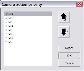
16 Alarm Actions Tab (Fig. 2-7) (Fig. 2-7) The Device Selection button will bring up the Device Select dialog box. (Fig. 2-8) Select your supported alarm relay controller from the Type drop down box. To configure the communication settings for your alarm relay controller select the COM Port button, which will bring up the Communication Port dialog box. (Fig. 2-9) Set the correct device settings, refer to the manufacturer's specifications, using the associated drop down boxes. The Camera Priority button will open the Camera Action Priority dialog box. (Fig. 2-10) Here you can raise or lower the priority of individual channels. When either the Alarm Trigger Single Screen or Motion Trigger Single Screen feature is enabled, the channel with the highest priority will remain visible. This feature brings the alarm condition to your attention and will not change without user input, either by double-clicking the single screen or by selecting one of the Grid Layout buttons. The Popup E-Map check box enables the automatic showing of the E-Map when an alarm condition is detected. The Pre-recording check box, when enabled, will record seconds of video before the alarm condition happened. This will help aid in determining what events led up to the alarm condition. 16
")
 17")
17 (Fig. 2-8) (Fig. 2-9) (Fig. 2-10) 17

18 The Alarm Recording check box will toggle alarm recordings. Alarm conditions include motion detection and external sensor triggers. The Show Motion Area check box toggles the motion detection zone box on the Live Preview. The Enable Motion Log check box will enable motion detection based alarm condition triggering. This must be enabled for the E-map feature to pop-up on motion detection. It is also required for motion detection based triggering. The Motion Trigger Single Screen check box will maximize any video channel that detects motion. If more than one video channel detects motion the Motion Trigger Single Screen will show the video channel with the highest priority based on the Camera Priority. The Alarm Trigger Single Screen check box will maximize any video channel associated with an alarm sensor that has been triggered. The Error/Motion Output Trigger check box will enable motion detection based external alarm relay controller triggering. This must be enabled if you want motion detection to trigger an external alarm device. The Show Local Alarm Light check box toggles the display of a visual alarm light in the center of the screen during alarm conditions. The Enable Voice Alarm check box toggles an audible sound that plays through the speakers connected to the Vegas Valley DVR Server when an alarm condition is detected. To select the sound to be played select the Alarm Response button. The Alarm Response Setting dialog box will appear. (Fig. 2-11) (Fig. 2-11) 18

19 The Alarm Response tab will allow you to set separate sound files for each sensor connected through the alarm relay controller when they are triggered. The Motion Response tab will allow you to set separate sound files to be played for each individual channel when motion is detected. The Error Response tab will allow you to set a single sound file for any error condition that occurs. To configure a sound file left-click on the desired sensor/channel and select the File Selection button. The standard Windows Open dialog box opens. Navigate to the directory where your sound file is located and highlight it. Once the sound file is highlighted, select the Open button to apply that sound file. Relation Tab (Fig. 2-12) (Fig. 2-12) 19

20 The Relation tab allows you to configure any supported alarm relay controller that you have connected to the Vegas Valley DVR Server. To configure an individual sensor connected to the alarm relay controller select the sensor from the Sensor list. Once the sensor is highlighted select the Sensor Property button. The Sensor Property dialog box will appear. (Fig. 2-13) Determine if your sensor is a high or low level trigger and select the appropriate radio button. The ID field corresponds to which input you have your sensor connected to on the alarm relay controller. Input the proper number in the ID field. Using the Description field, you can give your sensors different names. Once you have your sensor configured select the Ok button to return to the Relation tab. (Fig. 2-13) You can link each individual sensor to any number of video channels or alarm outputs on the alarm relay controller. To configure the alarm outputs select the output number that the alarm device is connected to on the alarm relay controller by checking the box in Link To Output. Enter a description and select either High or Low for the Trigger. You can also select a High Level Pulse or a Low Level Pulse. The Pulse will trigger the output for a short time and then turn off. You can link several alarm outputs to a single sensor. To link a sensor to a video channel for recording select the sensor from the Sensor List. Then check the box next to the desired video channel under the Link To Video Channel. The Preset column allows you to enter a PTZ Preset Position number that the PTZ camera will automatically move to when the sensor is triggered. The Snapshot column will allow you to save a snapshot when the sensor is triggered. The Output column allows you to assign an alarm output number that will trigger the corresponding alarm device connected to that specific output on the alarm relay controller. The Matrix In column will display the video channel number that is entered on Public View 01. Guard Schedule Tab The Guard Schedule tab is where you configure the schedule for each sensor connected to the alarm relay controller. Unless a schedule is set and activated, the sensor(s) attached to the alarm relay controller will be disabled. Refer to the Schedule Tab section for setup. 20
 Locate the supported PTZ camera on the list then select the Ok button.")
21 PTZ Tab (Fig. 2-14) (Fig. 2-14) To configure a PTZ camera select the video channel that the PTZ camera is connected to in the Channel List. Select the Load button to bring up the Predefined PTZ Ctrl Code dialog box. (Fig. 2-15) Locate the supported PTZ camera on the list then select the Ok button. Once the protocol is configured, assign the correct address to the PTZ camera using the Address Index drop down box. Select the COM Port button to bring up the Communication Port dialog box. (Fig. 2-16) Configure each drop down box as specified by the PTZ camera manufacturer and select the Ok button to return to the PTZ tab. 21
 To select an external PTZ control device, such as a PTZ joystick,")

22 (Fig. 2-15) (Fig. 2-16) To select an external PTZ control device, such as a PTZ joystick, select the supported device from the Keyboard drop down box and select the COM Port button to bring up the Communication Port dialog box. (Fig. 2-16) Configure each drop down box as specified by the manufacturer. 22

23 Advanced Tab (Fig. 2-17) Video Standard: During the Initial Startup the video standard was already selected and should not need to be configured. Using the Date Style drop down box you can change how the date is displayed on the OSD. Recording Setup: The Single File Recording Time allows you to select the maximum amount of time before a new recording file is created. Remember that you cannot create a clip that spans multiple recording files and that the longer the Single File Recording Time is the longer it will take to load before playing back. The Minimal Disk Space is the amount of free space needed on a partition to record video to. Once this value is reached the Vegas Valley DVR Server will automatically free up more disk space to continue to record. The Auto Overwrite feature will automatically free up disk space (this will delete the oldest video recording files) and continue to record. The Disk Switching Alert will open a message box every time the server starts recording video to a different partition. You must click the Ok button before the Vegas Valley DVR Server will start recording again. (Fig. 2-17) 23

 This dialog box will appear at the bottom of the screen and display various messages pertaining to the Vegas Valley DVR Server.")
24 Others: The High-Quality Playback check box changes the playback quality. The Voice Chat check box toggles the ability to use a microphone and speakers to talk between the Server and the Client. The first time the Voice Chat is activated the Windows Sound Configuration will open and you will need to configure the microphone. The Messenger Service check box enables the Messenger Service dialog box pop-up. (Fig. 2-18) This dialog box will appear at the bottom of the screen and display various messages pertaining to the Vegas Valley DVR Server. The Audio Preview check box will toggle the Live Preview Audio in the Main DVR Screen. It will not affect the audio recording. The Status Info check box toggles the display of the recording status information on each video channel preview image. The Instant Playback check box toggles the Instant Playback feature. (Fig. 2-18) The Watchdog drop down box allows you to setup a hardware watchdog. Use the COM Port button next to the Watchdog drop down box to configure the watchdog settings according to the manufacturer. The Matrix drop down box will allow you to select any of the supported matrix cards. Depending on the manufacturer you may or may not need to configure the COM port settings using the COM Port button. The Snapshot Path is the absolute path where all the snapshots taken will be stored. To select a different location select the Open button (open yellow folder) and select the desired directory. To change the name of the video channels select the Channel Description button. Type in a name for each channel in the Camera Description field. (Fig. 2-19) You can add an extended description to each channel by clicking the Extend Info button. (Fig. 2-20) The Extended Info is only editable here in the Setup Menu, you cannot change the text while viewing the Extended Info in the Live Preview mode. (Fig. 2-19) 24


25 (Fig. 2-20) To configure the storage locations select the Disk Group Setup button. (Fig. 2-21) Select a disk group from the Group drop down box. All available partitions will be displayed. Check/un-check the box next to each partition to add/remove it from the disk group. You can assign different disk groups to different video channels using the Camera Tab. (Fig. 2-21) The Import Config and Export Config buttons will appear on all tabs. You can choose to import or export your Vegas Valley DVR Server configuration. This allows you to copy your configuration to another Vegas Valley DVR Server to quickly setup multiple DVR Servers or to backup your settings in case of emergency. To export your configuration select the Export Config button. The standard Windows Save dialog box appears where you will be able to choose the name and location to save your configuration file to. To Import a configuration file select the Import Config button. The standard Windows Open dialog box appears where you will be able to select a configuration file to import. Once you import a configuration file, the settings will be automatically applied. For some settings to take effect, you may need to restart the Vegas Valley DVR Server application. Environment Tab (Fig. 2-22) System Startup: To have the Vegas Valley DVR Server application automatically log into Windows XP/2000 on startup check the Auto Administrator Login When Windows Is Started check box. Be sure to use the Password button to input the Windows XP/2000 login information. To have the Vegas Valley DVR Server application start when Windows XP/2000 loads check the Auto Startup This Program check box. The Auto Reindex Recording Files check box will reindex all recorded video files after the Vegas Valley DVR Server has finished 25

26 loading. (Fig. 2-22) Environment: The Enable Client Connection check box needs to be checked to allow remote client users to connect to the server. A log is created for every day that the Vegas Valley DVR Server is running. To change the number of days that these logs are stored type in the desired number into the Log Info Keeping Period field. To have the Vegas Valley DVR Server automatically restart check the Auto Restart check box. To specify when this restart will happen select the desired day, hour, and minute using the corresponding drop down boxes. It is recommended to restart at least once a week. To shutdown automatically check the Auto Shutdown check box and configure the day, hour, and minute drop down boxes. Auto Shutdown will only exit the Vegas Valley DVR Server application which will stop all recording. To have the entire DVR system turn off check the Power Off When Shutdown check box. The server application can be scheduled to automatically start at a specific time. To enable this feature check the Auto Start check box and select the desired hour and minute using the drop down boxes. This feature requires a Watchdog unit to be spliced into the PSU. If no Watchdog unit is installed/configured correctly the Auto Start feature will function even if it is configured. To enable the Vegas Valley DVR Web Server check the Enable Local Web 26

 Input the desired port number for the HTTP Port, which is used for the Web Client, and the Server Message, which is used for the Client Application. (Fig.")
27 Server check box. The Local Web Server enables client access through Internet Explorer. For the Vegas Valley DVR Server/Web Server to be accessible from remote locations you must forward ports through the router to the DVR machine. To configure which port is used select the Network Ports button. The Network Ports Setting dialog box will appear. (Fig. 2-23) Input the desired port number for the HTTP Port, which is used for the Web Client, and the Server Message, which is used for the Client Application. (Fig. 2-23) To synchronize the system clock to the local time select the Adjust Clock button. (Fig. 2-24) The System Clock dialog box will appear and allow you to change the system time and date. (Fig. 2-24) The Auto Reindex Recording Files check box will automatically start the reindexing process after the Vegas Valley DVR Server application finishes loading. Due to imperfections in hard disk drive technology data corruption may occur. In this case you will need to reindex the recording files. The reindexing process scans each recorded video file and recreates the index file. Depending on how many recorded video files there are on the storage partitions this process may take up to two hours. If recorded video does not appear in the Playback mode or if the Playback mode takes more than five minutes to load it may indicate that there are missing or corrupt index files, you will need to reindex. During Daylight Savings when the time is set back one hour the Vegas Valley DVR Server will have two recordings for that same hour. To correct this situation you must reindex. 27


28 User Button The User button will allow you to add/delete users and to modify their permissions. There are several buttons on the top of the User Admin dialog box. (Fig. 2-24) Hover the mouse cursor over these buttons to see what each of them are. To delete a user from the system select the user from the list and select the Delete button. To configure an existing user select the Modify button. To add an additional user select the Add User button, the Modify User dialog box will appear. (Fig. 2-25) (Fig. 2-24) (Fig. 2-25) 28

29 Select the User level using the top radio buttons. The User Level determines clientside bandwidth priority. If a user with a higher User Level logs into the system and there is not enough bandwidth for all users, the user with the highest User Level will be allocated the required bandwidth. The users with a lower User Level will have their connection interrupted until other users disconnect from the system. Fill in the Username, Password, Retype Password, Full Name, and Description fields. You can disable a user by checking the Disable This User check box. This will not delete the user. To make a user the default user check the Default User check box. The default user is the user that automatically appears in the Lock/Exit/Login dialog boxes. To enable specific cameras to be viewed by the user select the Camera Access button. The Camera Access dialog box appears. (Fig. 2-26) Check or uncheck each camera that you want to enable/disable. To quickly enable all cameras select the Select All button. To quickly disable all of the cameras select the Clear button. (Fig. 2-26) To assign permissions to be granted to the user select the Authority button. The Assign Authority dialog box will appear. (Fig. 2-27) Check or un-check each of the selectable permissions for the user. To quickly remove all permissions select the Clear button. To quickly assign all permissions select the Select All button. To create a backup copy of the configured users select File and then Save As. The standard Windows Save dialog box opens. By default the user backup will save to the Config Files Backup directory inside the Vegas Valley DVR Server folder. To restore a User Backup File select File, then Load. The standard Windows Open dialog box will appear. Select the *.usr file to import. 29
 The E-Map feature is an advanced camera/sensor/alarm electronic map capable of embedding smaller maps inside of larger maps. (Fig.")

30 (Fig. 2-27) E-Map Button If this is the first time you have configured the E-Map you will see the E-Map dialog box. (Fig. 2-28) The E-Map feature is an advanced camera/sensor/alarm electronic map capable of embedding smaller maps inside of larger maps. (Fig. 2-28) Select the Define A Root Node button to select the root map, this root map is the top level map and can contain embedded maps, cameras, sensors, and alarms. The standard Windows Open dialog box will appear. The default directory for map images is C:\Unisight Softwares\E-map. Select the root map image from the list and select the Ok button. You will now see the E-Map dialog box with your root map image. The E-Map Control Buttons are on 30
 Select Map Node from the Node Type drop down box. Input a name for the child map in the Description field.")
31 the bottom of the dialog box. (Fig. 2-29) From left to right these are Zoom In, Zoom Out, Return To Parent Map, Fullscreen, Standard Zoom, and Move Thumbnail Map. (Fig. 2-29) To embed a map image inside the root map image right-click on the root map image. The E-Map Node dialog box will appear. (Fig. 2-30) Select Map Node from the Node Type drop down box. Input a name for the child map in the Description field. You can change the color of the Description text that appears on the map by using the Color button. Select the Open button (yellow folder) to select the child map image. The standard Windows Open dialog box will appear and you will be able to select the map image. (Fig. 2-30) Creating Cameras, Alarm Outs, and Sensors will create an icon on the E-Map that will act as a shortcut to the associated object. To add a camera to the E-Map right-click on the map image to open the E-Map Node dialog box. (Fig. 2-30) Select Camera from the Node Type drop down box. Type in the channel number in the Channel field and fill in the Description field. Once the camera icon shows up on the map image you can click and drag the icon to the desired location. Upon closing the E-Map Node dialog box you will be asked to save the changes. To use the E-Map select the E-Map button in the Live Preview mode. To view an embedded child map double-click the map icon. To bring up a video channel in Single Screen Preview double-click the camera icon. When you double-click the camera icon the E-Map will automatically close. You can also quickly clear all of the E-Map configurations and maps. Select the Remove Root button. This will clear all E-Maps and present you with the Define a Root Node button. 31

32 Log Button The Log button will open the Log Viewer dialog box. (Fig. 2-31) The log file will provide more information about how the the Vegas Valley DVR Server was functioning. Each log file is organized by date, there is one log file per day. You can sort by log entry type using the Type drop down box. You can also sort log entries by user with the Username drop down box. Use the Save button to create a backup copy of the log file. (Fig. 2-31) 32
 The version number will be displayed in the title bar in parenthesis after the Extra-function text.")
33 Extra Button The Extra button allows you to determine the version number that you are currently running. (Fig. 3-0) The version number will be displayed in the title bar in parenthesis after the Extra-function text. Each Extra Function has a shortcut key associated with it that is displayed before the button name. (Fig. 3-0) Extra Functions Snapshot F1: This button will bring up the Extra Functions dialog box. (Fig. 3-0) F2: This button will take a snapshot of the currently selected video channel and will be saved to the default directory of C:\Snapshot Data. 33
 Select the File menu, then select Open to open a snapshot image. Once the snapshot is loaded you can use various editing tools to enhance the image. (Fig.")
34 Snapshot Viewer Vegas Valley Video Systems F3: This button will bring up the Image Viewer and allow you to view, edit, and print any snapshot taken. (Fig. 3-1) Select the File menu, then select Open to open a snapshot image. Once the snapshot is loaded you can use various editing tools to enhance the image. (Fig. 3-1) PTZ Preset Position F4: This button will bring up the PTZ Preset Position Control dialog box. (Fig. 3-2) Begin by selecting the video channel that has a PTZ camera configured in the Live Preview. Select the PTZ button to display the PTZ camera controls. Point the PTZ camera at the desired location and select PTZ Preset Position button in the Extra Functions dialog box or by pressing F4 on the keyboard. Left-click number 01 and select the Setting button. The Setting button stores the PTZ orientation to the selected number. Now select the Option button. This will open the PTZ Preset Point Info dialog box. (Fig. 3-3) To have this PTZ preset position be a cruise point check the Act As A Cruise Point check box. To have the PTZ camera pause at this point during cruising enter a number (in seconds) for the Staying Time field. The Description field allows you to assign a name to the cruise point. The Clear button will remove the PTZ cruise point information. These cruise points are stored in the PTZ camera itself and cannot be erased by the Vegas Valley DVR Server application. To initiate the PTZ Cruising feature select the Cruise button. Each time the Vegas Valley DVR Server application is closed PTZ cruising is stopped and will not start until the Cruise button is selected again. To have the PTZ camera orientate to a saved PTZ Preset Point select the number of the preset and select the Locate button. 34
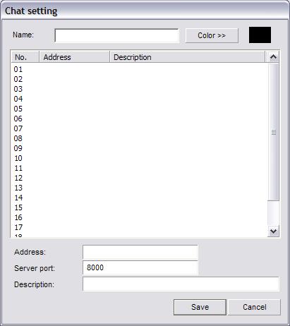
 Set a name for the chat room using the Name field.")

35 (Fig. 3-2) (Fig. 3-3) Text Chat F5: This button will bring up the Chat Room dialog box. (Fig. 3-4) To configure a chat room select the Setting button. The Chat Setting dialog box will appear. (Fig. 3-5) Set a name for the chat room using the Name field. Input the Address (LAN IP), Server Port (8000 by default), and Description using the fields at the bottom of the window. Select the text color using the Color button. This is the color of the text you type, the other users have their own separate colors. Select the Save button to return to the Chat Room dialog box. Type in a message in the bottom text field and select the Send button to have your message appear. The Clear All button will remove all sent/received text messages from the chat window. 35
")
36 (Fig. 3-4) (Fig. 3-5) 36
 The Waveout volume is the volume of the Live Audio Preview. The Main Volume includes the Waveout Volume along with other sounds such as the alarm sounds. (Fig.")
37 Audio Volume Vegas Valley Video Systems F6: This button will allow you to adjust the volume of both the Waveout volume and Main Volume. (Fig. 3-6) The Waveout volume is the volume of the Live Audio Preview. The Main Volume includes the Waveout Volume along with other sounds such as the alarm sounds. (Fig. 3-6) Instant Playback F7: This button will open the Instant Playback dialog box. (Fig. 3-7) Drag the Time Slider under the video feed to quickly fast forward/backward. The buttons (from left to right) are Save, Fullscreen Mode, Decrease Speed, Play, Pause, Stop, Increase Speed, Snapshot, and Exit. The Save button will open the standard Windows save dialog box and allow you to backup the Instant Playback video. The Fullscreen Mode button will maximize the Instant Playback video. To return from Fullscreen Mode right-click the mouse button anywhere on the screen. Use the Increase/Decrease Speed buttons to make the video play faster or slower. You can play as slow as ¼ real time speed and as fast as 16x real time speed. The Pause button will freeze playback and show a still frame. The Stop button will stop playback and move the time slider to the beginning of the Instant Playback video. The Play button will resume playback starting where the time slider is positioned. The Snapshot button will take a still image and allow you to save it. The Exit button will close the Instant Playback dialog box. Once you close the Instant Playback dialog box a new period of video may appear if you re-enter Instant Playback depending on the length of time that has passed since you first initiated Instant Playback for that video channel. When you first enable the Instant Playback feature in the Setup menu, it may take up to an hour to successfully cache video for all the video channels. 37
 The Public View drop down box will select the Public View grid number. Public View 01 is the analog monitor connected to the first port of the Matrix card.")
38 (Fig. 3-7) Start A Voice Chat F8: This feature is a 2-way full duplex voice chat. It is initiated on the client side. Matrix Control F9: This button opens up the Matrix Switch dialog box. (Fig. 3-8) The Public View drop down box will select the Public View grid number. Public View 01 is the analog monitor connected to the first port of the Matrix card. Public View 02 is the analog monitor connected to the second port of the Matrix card. Once you have selected the Public View select any video channel to be shown on that Public View by left-clicking the channel number from the list. Once selected it will display Show next to the channel number. The Option button will open the Matrix Control Info dialog box for the currently selected video channel number. (Fig. 3-9) The Description field allows you to rename the video channel. The Relation To Public View check box will add that video channel number to the auto switching list. The channel number will display Enabled under the Link column if added to the auto switching list. The Switch Interval field allows you to input the number of seconds you want that video channel to be displayed before switching to the next video channel. Select the Ok button to save the changes. The Enable Auto Switching check box on the Matrix Switch dialog box must be checked for the Public View to start the Auto Switch feature. Due to hardware limitations the same video channel cannot be displayed twice at the same time. If you configure the Matrix Switch this way a blue screen will appear on the analog monitor. 38
 External Command F10: This button will execute any")
39 (Fig. 3-8) (Fig. 3-9) External Command F10: This button will execute any external command that has been configured. 39
 You will be able to adjust the brightness, contrast, saturation, and hue for the currently selected video channel. Select the Default button to restore all parameters to their original values.")
 This window will display each connected user, their IP address, and which video channel they are connected to.")
40 Video Parameters Vegas Valley Video Systems F11: This button will open the Video Parameters dialog box. (Fig. 3-10) You will be able to adjust the brightness, contrast, saturation, and hue for the currently selected video channel. Select the Default button to restore all parameters to their original values. (Fig. 3-10) Remote Connection Control F12: This button will open the Remote Connect dialog box. (Fig. 3-11) This window will display each connected user, their IP address, and which video channel they are connected to. This list is automatically updated, but you can force an update and get the latest list by selecting the Refresh button. To disconnect all connected remote clients select the Disconnect All button. To disconnect a single video channel connection select the desired channel and select the Disconnect button. (Fig. 3-11) Switch Video Channel Tab: This button will cycle the video channel selection to the next video channel. You will notice the white highlight box surrounding the currently selected video channel. 40

41 All Channels Start Recording Vegas Valley Video Systems Ctrl+R: This button will start a recording in Manual Recording Mode on all channels if not currently recording. If a channel is disconnected recording will not start for that individual channel. All Channels Stop Recording Ctrl+S: This button will stop recording on all channels if not currently recording in Continuous Mode or Motion Detection Mode. If motion is detected the Vegas Valley DVR Server will start recording again for each video channel that motion has been detected. Adjust PTZ Speed Ctrl+P: This button will allow you to change the speed at which the PTZ camera moves when using the PTZ Control buttons. This is especially useful when panning/tilting while zoomed in. Pressing Ctrl-P on the keyboard will bring up the Adjust PTZ Speed dialog box. (Fig. 3-12) Use the Horizontal/Vertical Speed sliders or enter a number in the Horizontal/Vertical Speed fields. This will not change the speed at which the PTZ camera moves when the PTZ camera in Cruising. (Fig. 3-12) Force To Switch Recording File Ctrl+C: This button will create a new recording file for each video channel that is currently recording even if the Single File Recording Time has not been reached. All Channels Start Auto-Pan Ctrl+K: This button will start the PTZ Cruise for each PTZ camera configured with PTZ Presets. 41
42 Running E-Map Vegas Valley Video Systems Ctrl+A: This button will open the E-Map dialog box only if the E-Map has already been configured. Activate Motion Detection For All Ctrl+M: This button will start motion detection based recording on all channels if the Motion Schedule is not already set and activated. Deactivate Motion Detection For All Ctrl+D: This button will stop motion detection based recording on all channels if the Motion Schedule is not already set and activated. Channel Extend Info Ctrl+E: This button will open the Notice dialog box containing the Extend Info for the currently selected video channel. This is only a display, the text is not editable. To edit the Channel Extend Info use the Extend Info button in Setup -> Advanced Tab -> Channel Description -> Extend Info. Reindex Recording Files Ctrl+Z: This button will start the Reindexing process. All Channels Stop Auto Pan Ctrl+L: This button will stop the PTZ Cruise for all PTZ cameras. 42
 Use the arrows to pan and tilt. The Focus buttons will readjust lens focus. The Iris buttons wil open and close the iris letting in more/less light. The Zoom buttons will zoom in/out.")
43 PTZ Button To gain control of a configured PTZ camera start by selecting the video channel in the Live Preview. Select the PTZ button, the panel will expand the PTZ controls. (Fig. 4-0) Use the arrows to pan and tilt. The Focus buttons will readjust lens focus. The Iris buttons wil open and close the iris letting in more/less light. The Zoom buttons will zoom in/out. The Auto Rotation button will slowly rotate the PTZ camera. Not all PTZ functions under the PTZ button are supported by all PTZ cameras and may not work. There are three other Function buttons that operate special PTZ camera functions such as wipe/clean glass and heater control. The F1/F2/F3 buttons may not be supported on all PTZ cameras. (Fig. 4-0) 43

44 Playback Mode The Playback mode allows you to review and backup recorded video files. (Fig. 5-0) You can playback a maximum of 16 channels at once. You can fast forward at 16x. Take note that playback at 16x speed on all 16 channels would be the same as playing back 256 channels at normal speed. Playback at 4x speed on all 16 channels would be the same as playing back 64 channels at normal speed. The PC system used for playback may not have the system resources to playback that many channels at once or at that playback speed. Be sure to monitor your CPU Usage in the Playback Information Window and HDD access lights on the chassis when playing back recorded video files to avoid unwanted issues. (Fig. 5-0) 44
 The channel number (Channel), video file size in Mb (Size), video file length in seconds (Length), bandwidth in Mbps (Bandwidth), volume level (Volume), playback speed (Speed) in green. (Fig.")
45 Playback Information Window The Playback Information Window displays the current date, time, and CPU usage in white on the top of the display. (Fig. 5-1) The channel number (Channel), video file size in Mb (Size), video file length in seconds (Length), bandwidth in Mbps (Bandwidth), volume level (Volume), playback speed (Speed) in green. (Fig. 5-1) Channel Grid The channel grid contains the playback video. This is where you will see all of your video recordings. You can select each channel by left-clicking on the desired grid square, this will also activate the audio for that channel. There is a full screen mode that you can toggle by clicking the right mouse button on the video feed. Grid Layout The arrangement of the Channel Grid is easily configured by 9 buttons. Hover your mouse cursor over these buttons for a description of each of the layout buttons. (Fig. 5-2) You can also zoom in and out by using the two buttons with the magnifying glass. To zoom in select the Zoom In button. Place the cursor over the currently selected video channel and left-click and drag a square around the area you want to zoom in on. To further zoom in repeat the same process. You will reach a point at which you cannot zoom in any further. To zoom out select the Zoom Out button. For each step that you zoomed in you must also zoom out. If you zoomed in twice, you must zoom out twice. (Fig. 5-2) Calendar The calendar displays days that have recorded video footage in red, days with no video footage are displayed in black. (Fig. 5-3) To change months use the single arrow buttons. To change years use the blue double arrow buttons. To quickly change to the current day select the Today button. 45

 Playback Node Tree The Playback Node Tree allows you to switch between playback modes. (Fig. 5-5) When entering into the Playback Mode the Local Files is selected by default.")
46 (Fig. 5-3) File List You can also search for video recordings using the File List. (Fig. 5-4) Simply select the date from the Date drop down box and the channel name from the Cameras drop down box. You will see a range of time indexes. Each time index is a single video recording file. To playback a recorded file select the desired time index and select the Play button. To playback a series of recorded video files sequentially hold down the Ctrl button on the keyboard and select more recorded video files from the list. (Fig. 5-4) Playback Node Tree The Playback Node Tree allows you to switch between playback modes. (Fig. 5-5) When entering into the Playback Mode the Local Files is selected by default. Local Files will display all video recording files located on the Vegas Valley DVR Server's Disk Groups. This mode will cache each recorded video file before playing back and may not always be synchronized with other playing recorded video files. To synchronize the playback select the Local SYNC Playback under Custom Server. This mode will delay the playback of recorded video files until each channel is synchronized. 46
 From left to right these are Previous File, Decrease Speed, Step Backward, Stop, Play, Pause, Step Forward, Increase Speed, Next File, Multiplay, and Stop All. (Fig.")
47 (Fig. 5-5) Playback Controls These controls will allow you to control the various aspects of playback. (Fig. 5-6) From left to right these are Previous File, Decrease Speed, Step Backward, Stop, Play, Pause, Step Forward, Increase Speed, Next File, Multiplay, and Stop All. (Fig. 5-6) Previous File Jumps to the beginning of the previous video recording file. Decrease Speed Slows down the playback speed to a minimum of ¼ real time speed. Step Backward Moves the time slider back one frame and also pauses playback. Stop Stops playback of the currently selected video recording file. Play Starts playback of the currently selected video recording file. Pause Freezes playback of the currently selected video recording file. Step Forward Moves the time slider forward one frame and pauses the video playback. Increase Speed Increases the playback speed up to 16x real time speed. Next File Jumps to the beginning of the next video recording file. Multiplay Starts playback of all selected video channels. To select/de-select a video channel left-click on the Cam buttons in the Camera column on the bottom left of the screen. To quickly select all video channels double-click any of the Cam buttons. To quickly de-select all channels right-click any of the Cam buttons. The recorded video files may not playback completely synchronized. The Vegas Valley DVR Server caches each file sequentially before playing back the selected recorded video files. To synchronize the playback, use the Local SYNC Playback. Stop All Stops playback on all video channels. The Volume Buttons will increase/decrease the volume of all video channels. (Fig. 5-7) The Mute buttons will enable/disable the audio playback. The Exit button will close the Playback mode and return to Live Preview. (Fig. 5-7) 47

48 The Clip button will allow you to extract a video clip from the currently playing video file. (Fig. 5-7) To start a video clip select the Clip button. The Clip Video File dialog box will appear. (Fig. 5-8) A Start Time will be displayed but no Stop Time. Select the Ok button to start recording a clip. The Clip Video File dialog box will disappear and the recorded video file will continue to play. Once you have passed the video portion that you want in the clip select the Clip button again. The Clip Video File dialog box will appear. (Fig. 5-8) A Start Time and Stop Time with both be displayed. To save the clip select the Ok button. The Files Backup Manager will appear. (Fig. 5-9) (Fig. 5-8) (Fig. 5-9) Type in a name for the clip using the Filename field. Input a label for this backup using the Label field. Past labels will be displayed in the Label drop down box. Select the Backup button to continue and choose a location to save to. The Select Path dialog box will appear. (Fig. 5-10) Select the device to save the video clip file to using the Device Type drop down box. Select the appropriate drive to save the clip file to using the Drive List drop down box. The Free Space and Space Needed displays will automatically update. If you are backing up to a CDR or DVDR be sure to insert the CD/DVDR into the drive before continuing. Select the Save button to finish the clip creation process. 48
")
49 (Fig. 5-10) (Fig. 5-11) 49

50 The Smart Search button will open the Smart Search dialog box. (Fig. 5-11) The Smart Search is divided into two sections, the Video Preview Windows and the Smart Search Control Set. The Video Preview Windows display the Playback video and the Search video. The Control Set displays all the Smart Search buttons along with the Video Results. With the Smart Search feature you are able to search through previously recorded video files for motion in the motion zones you create. You can also bookmark a Smart Search session for later review. To begin a Smart Search select the Setup button. The Setup dialog box will appear. (Fig. 5-12) Select the video channel you want to search through using the Channel drop down box. Next fill out the Start Time by selecting a start date with the drop down box and a start time using the time field. Then fill out the End Time by selecting an end date with the drop down box and an end time using the time field. After you have selected your searching range select the Ok button. The Setup dialog box will disappear and you will now see a video feed playing in the Search Window. You can change the recorded video file playing in the Search Window using the Previous Recorded Video File and Next Recorded Video File buttons. (Fig. 5-13) (Fig. 5-12) (Fig. 5-13) You can now create one or more motion zones, each with individual sensitivity settings, to search through the recorded video files. The currently selected motion zone will be highlighted white, the rest will be red. To cycle through the motion zones, use the Switch button. To remove the currently selected motion zone select the Delete button. To clear all motion zones select the Clear button. Left-click and drag a motion zone around the desired area. A white square will appear. Set the sensitivity for the motion zone(s) and select the Search button, a progress bar will appear to display the search progress. To resume the search select the Continue button. Once the search has been completed, the video results will be displayed. To play a recorded video file highlight the desired file and select the Play button. You can also Pause and Stop the video. Select the Snapshot button to take a 50

 Input the name of your saved search in the Bookmark field.")
51 snapshot of the entire video frame. To create a backup select the recorded video file by leftclicking on them. To selected multiple recorded video files hold down the ctrl key and left-click on multiple recorded video files. Select the Backup button to backup the selected video files. You can save a Smart Search and review it at a later time. Select the Bookmark button to open the Bookmark dialog box. (Fig. 5-14) Input the name of your saved search in the Bookmark field. You can also type in a description of the saved search in the Description field. To save the search select the Ok button. (Fig. 5-14) (Fig. 5-15) 51
52 To review a saved Smart Search select the History button in the Smart Search dialog box. The History dialog box will appear. (Fig. 5-15) Select the date in which the search was bookmarked using the Date drop down box, then select the name of the bookmark from the Bookmark drop down box. The Delete button will erase the currently selected bookmarked smart search. The Clear All button will erase all bookmarked smart searches. Use the Select All button to select all recorded video results. The Inverse button will change the selection to the exact opposite of the currently selected recorded video results. The Delete button will remove the selected recorded video file from the bookmarked smart search. You can also backup recorded video files from the History dialog box. Select the Backup button to backup the selected video recording files. Use the Exit button to close the Smart Search and History dialog boxes. Snapshot The Snapshot button will take a still image of the currently selected video file. (Fig. 5-16) You can then save this image for later review. (Fig. 5-16) Browse and Print Image File The Browse And Print Image File button will open the Image Viewer. (Fig. 5-17) The Image Viewer allows you to edit and print out saved snapshots. When a snapshot is printed additional information is automatically added to the printout, including the time the snapshot was taken, DVR name, time the snapshot was printed, and channel number. (Fig. 5-17) Manual Selecting File If you have recorded video files stored in a location other than the default directory the video recordings will not show up in the Calendar or the File List. Use the Manual Selecting File button to access the recorded video files. (Fig. 5-18) To browse for recorded video files select the Open button (yellow folder). (Fig. 5-19) The standard Windows Browse dialog box will appear. Locate the folder that the recorded video files are stored in and select the Open button. You will be returned back to the Select Video File dialog box. You can sort the recorded video files by channel, recording type, and by time index. Once you locate the recorded video file you wish to play left-click on it so that it highlights. Select the Ok button and the video file will begin to play. (Fig. 5-18) 52
 From here you are able to backup multiple cameras from multiple days simultaneously.")
53 (Fig. 5-19) Backup Files The Backup Files button will open the Backup Recording Data dialog box. (Fig. 5-20), (Fig. 5-21) From here you are able to backup multiple cameras from multiple days simultaneously. During the last step of the backup process the player software is automatically copied over along with the recorded video files. No other software or codecs are needed to review the saved video on a different Windows XP/2000 PC system. (Fig. 5-20) 53
54 (Fig. 5-21) Use the Date drop down boxes to set a date range to filter the results. Use the Time fields to set a start time and end time to filter the results. The Recording Type drop down box will allow you to further filter the results by searching for only Motion/Manual/Continuous/ Network/Alarm based recordings. To backup multiple cameras check the box next to the channel name. The Select All button will automatically check all cameras. The Inverse button will select the exact opposite of the currently selected cameras. Select the Search button to begin the recorded video file search. In the results the Start/Stop Time, Length, Channel, Mode, and Disk will be displayed. Left-click a video file to select it. Hold down the ctrl key on the keyboard and left-click to select multiple recorded video files to backup. The Select All Files button will select all results. The Inverse button will select the exact opposite of the currently selected video files. The Cancel button will close the Backup Recording Files dialog box. When you have selected the desired recorded video files select the Backup button. The Files Backup Manager dialog box appears. (Fig. 5-22) 54

 Select the backup device using the Device Type drop down box. If you are backing up to a CDR or DVDR ensure that the blank disc is in the drive.")
55 (Fig. 5-22) The Backup Tools button will open up Nero (if configured in the.ini file) and allow you to add more files to a CD session. The USB Devices button will allow you to remove USB devices that you do not want to show up in the Device Type drop down box when finishing the backup process. Type in a name for the backup in the Label drop down box. Select the Backup button. The Select Path dialog box will appear. (Fig. 5-23) Select the backup device using the Device Type drop down box. If you are backing up to a CDR or DVDR ensure that the blank disc is in the drive. If you select Compact Disc the Drive List drop down box will automatically select the CDR/W drive. Select the Save button to complete the backup process. (Fig. 5-23) 55
DVR System. NW9400 Manual Version Rev 1.2
 NW9400 Manual Version 2.8.0131 Rev 1.2 1 Table of Contents DVR System System Requirements...5 Server Hardware Requirements...5 Server Software Requirements...5 Client Hardware Requirements...5 Client Software
Unisight DVR System. Unisight DVR Manual. Version Rev 1.0
 Unisight DVR Manual Version 1.8.0131 Rev 1.0 1 Table of Contents System Requirements...5 Server Hardware Requirements...5 Server Software Requirements...5 Client Hardware Requirements...5 Client Software
Unisight DVR System. Unisight DVR Manual. Ver rev1.3.4
 Unisight DVR Manual Ver2.7.1027 rev1.3.4 1 Table of Contents System Requirements.8 Unisight DVR Server.. 8 Server Hardware Requirements...8 Server Software Requirements 8 Client Hardware Requirements...
Unisight Digital Technologies. Unisight DVR Manual Client
 Unisight DVR Manual Client 1 Table of Contents Initial Startup...4 Initial Startup...4 Channel Grid...6 DVR Information Window...6 Grid Layout Buttons...7 Camera Status LEDs...7 Extra Function Buttons...7
PROFESSIONAL PROTECTION INCORPORATED
 PROFESSIONAL PROTECTION INCORPORATED EAGLE EYE DIGITAL VIDEO RECORDING AND SURVEILLANCE SYSTEMS 1101 Tyvola Road Suite 202 Charlotte North Carolina 28217-3515 Business: (704) 523-1660 Facsimile: (704)
NVMS User Manual. Version 2.1.0
 NVMS-1000 User Manual Version 2.1.0 Contents 1 Software Introduction... 1 1.1 Summary... 1 1.2 Operation Environment... 1 1.3 Install and Uninstall... 2 1.3.1 Install the Software... 2 1.3.2 Uninstall
NVMS User Manual
 NVMS-1000 User Manual Contents 1 Software Introduction...1 1.1 Summary... 1 1.2 Operation Environment... 1 1.3 Install and Uninstall... 2 1.3.1 Install the Software... 2 1.3.2 Uninstall the Software...
NVMS User Manual
 NVMS-1000 User Manual Contents 1 Software Introduction...1 1.1 Summary... 1 1.2 Operation Environment... 1 1.3 Install and Uninstall... 2 1.3.1 Install the Software... 2 1.3.2 Uninstall the Software...
USER MANUAL. Mac Version
 USER MANUAL Mac Version Contents 1 Software Introduction... 1 1.1 Summary... 1 1.2 Install and Uninstall... 1 1.2.1 Install the Software... 1 2 Login Software... 3 2.1 Login... 3 2.2 Control Panel Instruction...
NVMS1000. User Manual
 NVMS1000 User Manual Contents 1 Software Introduction... 1 1.1 Summary... 1 1.2 Operation Environment... 1 1.3 Install and Uninstall... 2 1.3.1 Install the Software... 2 1.3.2 Uninstall the Software...
NVMS1000. User Manual
 NVMS1000 User Manual Contents 1 Software Introduction... 1 1.1 Summary... 1 1.2 Operation Environment... 1 1.3 Install and Uninstall... 2 1.3.1 Install the Software... 2 1.3.2 Uninstall the Software...
User s Manual of DVR ULTIMAX. Remote Client Software V wersja 2.40
 User s Manual of DVR ULTIMAX Remote Client Software V 4.0.1 ULTIMAX-304 ULTIMAX-308 ULTIMAX-316 ULTIMAX-504 ULTIMAX-508 ULTIMAX-516 ULTIMAX-704 ULTIMAX-708 ULTIMAX-716 wersja 2.40 Index 1 Software Install,
Central Management Software. Cam Viewer 3 Lite. User Manual
 Central Management Software Cam Viewer 3 Lite User Manual Version 1.0.0 Table of Contents 1. System Requirement...4 2. Software Installation...5 3. Configuration Wizard...9 3.1 Channel...10 3.1.1 Adding
YesCam View User Manual For Easy Connection YesCam Series
 YesCam View User Manual For Easy Connection YesCam Series Seeing the video from anywhere Version:1.2.4 Date:2015.02.3 1 Table of Content 1. Introduction...4 2. System Requirement...4 3. Install YesCam
Intelligent Security & Fire Ltd
 Copyright 2007-2009 Cortex Global Table of contents: Introduction... 3 1. Login... 3 1.1 Advanced login options... 4 2. Preview... 5 2.1 Main menu... 6 2.2 Camera list... 6 2.3 Main display... 6 2.4 Maps...
SKY l SYS DVR USER S MANUAL TABLE OF CONTENTS. Skydreamers Systems DVR Page 1
 TABLE OF CONTENTS Main System Application (Control) SERVER Startup Screen 6 Login/Logout/Shutdown 7 Control Screen 7 Setup 7 System Power Management 8 Auto Switching Interval 8 E-map 8 TV-Out 8 On-screen
Digital Recorder End User Guide. Official UK distribution partner
 Digital Recorder End User Guide Official UK distribution partner 2 Installer Information Contents General Operation Mouse Operation Logging into the System Quick Menu PTZ Control 4 5 5 6 Playback Operation
SecuGuard. Basic 5.0. User s manual. Dec Version: 5.0.x
 SecuGuard Basic 5.0 User s manual Dec. 2009 Version: 5.0.x SecuGuard Basic System Requirement...5 Installation...6 Before Installing the Software... 6 Starting the Installation... 6 Quick Start...9 Install
Digital Recorder End User Guide
 Digital Recorder End User Guide metcalfeallen www.metcalfeallen.co.uk - 01884 38222 - admin@metcalfeallen.co.uk Installer Information Metcalfe Allen Ltd Unit 7 Saunders Way Kingsmill Industrial Estate
Multi-NVR Manager. Quick Start Configuration Usage
 Multi-NVR Manager Quick Start Configuration Usage 2014. All rights are reserved. No portion of this document may be reproduced without permission. All trademarks and brand names mentioned in this publication
Pro7400H1 Hybrid DVR User Manual
 Pro7400H1 Hybrid DVR User Manual User Information Admin User Name: Admin Password: IP Address: System Name: Table Of Contents 1. Menu Operation... 4 1.1 Main Menu... 4 2. Start Up/Shutdown System... 5
W Box VMS BOX T E C H N O L O G I E S.
 W Box VMS BOX T E C H N O L O G I E S www.wboxtech.eu Contents Contents... 1 Overview... 3 1.1 Description... 3 1.2 Running Environment... 3 1.3 Function Modules... 3 Live view... 6 2.1 User Registration
Pro71600N3 NVR User Manual
 Pro71600N3 NVR User Manual User Information Admin User Name: Admin Password: IP Address: System Name: Table Of Contents 1. Menu Operation...4 1.1 Main Menu...4 2. Start & Shutdown System...5 2.1 Start
VMS-A1 Client Software. User Manual
 VMS-A1 Client Software User Manual Contents Contents... 2 Chapter1. Overview... 4 1.1 Description... 4 1.2 Features & Functions... 4 Chapter2. Update Info... 6 Chapter3. Starting VMS-A1... 7 3.1 Installing
SecuGuard. Basic 5.0. Version: xxx
 SecuGuard Basic 5.0 Ł` ˆª Ø Version: 5.0.2.xxx SecuGuard Basic ` Ø ˆ ˆ...6 ˆ Ø...7 Ł ˆ Ø»ˆÆ ˆ`... 7 ˆŁ` ˆ Ø»ˆÆ ˆ`... 7 Ø Æ Ł...10 Ø IP Camera(s)... 10 Ł` IP Camera(s)... 10 ˆ Ø Ł ˆ ˆ :... 14 Playback:...
NetClient software user manual
 NetClient software user manual 1-1. General information Net Client is an application which provides users not only viewing and controling remote DVRs, but also receiving realtime event data or alarm signals
DiViS Net (Integration)
") DiViS Net (Integration) Installation and User s Guide Ver 12.00.1 Digital Video Security System Digital Video Recorder www.divisdvr.com Chance-i USA Corp. *All contents of this document may change without
DiViS Net (Integration) Installation and User s Guide Ver 12.00.1 Digital Video Security System Digital Video Recorder www.divisdvr.com Chance-i USA Corp. *All contents of this document may change without
32 CHANNEL SURVEILLANCE SYSTEM MANUAL
 32 CHANNEL SURVEILLANCE SYSTEM MANUAL English version 1.0 SOFTWARE GUIDE Software Guide for Digimerge Networkable Cameras Copyright 2007 Digimerge Technologies Inc. 32-CH Surveillance System Note This
IP Solution Intelligent Surveillance Solution
 IP Solution Intelligent Surveillance Solution user s manual Table of Contents TABLE OF CONTENTS TABLE OF CONTENTS...1 SYSTEM REQUIREMENT...5 INSTALLATION...6 QUICK START...10 1. MAIN CONSOLE...14 1.1 Start...16
Using the VSOM Operator Pages
 CHAPTER 8 The VSOM Operator Pages provide access to features that video surveillance operators can use to view, record, search, and control video. This chapter describes the Operator Pages in detail. It
Lorex Client 7.0 & Lorex Message Master
 Lorex Client 7.0 & Lorex Message Master Software Manual English Version 1.0 MODELS: L19WD Series www.lorexcctv.com Includes L19WD800 & L19WD1600 Copyright 2008 Lorex Technology Inc. Table of Contents Table
Manual Version: V1.01. Video Management Server Client Software User Manual
 Manual Version: V1.01 Video Management Server Client Software User Manual Thank you for purchasing our product. If there are any questions, or requests, please do not hesitate to contact the dealer. Notice
Manual Version: V1.15. Video Management Software Guard Station User Manual
 Manual Version: V1.15 Video Management Software Guard Station User Manual Thank you for purchasing our product. If there are any questions, or requests, please do not hesitate to contact the dealer. Disclaimer
DiViS Net (Integration)
") DiViS Net (Integration) Installation and User s Guide Ver 12.12.0 Digital Video Security System Digital Video Recorder www.divisdvr.com DiViS DVR.com *All contents of this document may change without prior
DiViS Net (Integration) Installation and User s Guide Ver 12.12.0 Digital Video Security System Digital Video Recorder www.divisdvr.com DiViS DVR.com *All contents of this document may change without prior
NVR Client system. User Guide
 NVR Client system User Guide Content Chapter1 Start up and Main interface 2 1.1 Start up 2 1.2 Main interface 6 1.2.1 Interface description 6 1.2.2 Select playback channel 8 1.3 System Menu 11 1.3.1 Remote
Pro7804N1 NVR User Manual
 Pro7804N1 NVR User Manual Pro7804N1 User Manual BW R6.indd 1 User Information Admin User Name: Admin Password: IP Address: System Name: Table Of Contents 1. Menu Operation...4 1.1 Main Menu...4 2. Start
Figure 4-9. Click Finish button, system pops up a dialogue box. Click the OK button, the startup wizard is complete. See Figure 4-10.
 For detailed information, please refer to chapter 4.11.4.1.1. Figure 4-9 Finish button, system pops up a dialogue box. the OK button, the startup wizard is complete. See Figure 4-10. Figure 4-10 4.4 Preview
Digital Video Surveillance Center Management Software
 Digital Video Surveillance Center Management Software NVClient User Manual Revision: V3.2 Updated: 12-2011 Contents Chapter I General...- 3-1.1 INTRODUCTION... - 3-1.2 MAIN FUNCTIONS... - 3 - Chapter II
Video Management Software
 Video Management Software User Manual Web: europesecurity.eu Mail: info@europesecurity.eu Tel.: 0541 352 952 User s Manual 2 Contents CHAPTER : XMS CENTRAL USER MANUAL 1 PC REQUIREMENT 3 2 INSTALL 3 3
Table of Contents. Chapter 1 Overview In This Manual RASplus Features Product Information Chapter 2 Installation...
 Remote Administration System Plus (RASplus) Table of Contents Chapter 1 Overview... 1 1.1 In This Manual... 1 1.2 RASplus Features... 1 1.3 Product Information... 1 Chapter 2 Installation... 3 Chapter
Secure Guard Central Management System
 Speco Technologies, Inc. Secure Guard Central Management System Usage Information Contents 1 Overview... 7 2 Installation... 7 2.1 System Requirements... 7 2.2 System Installation... 7 2.3 Command Line
Central Management Software for NVR-915 / NVR-1615 CV5-M256
 Central Management Software for NVR-915 / NVR-1615 Table of Contents Chapter 1. Main Console... 4 1.1 Tool Bar... 4 1.2 NVR List... 5 1.3 Division List... 7 1.4 Group List... 9 1.5 PTZ Panel...11 1.6 Operation
Avigilon Control Center Web Client User Guide
 Avigilon Control Center Web Client User Guide Version: 4.12 Standard PDF-WEBCLIENT-S-E-Rev2 Copyright 2013 Avigilon. All rights reserved. The information presented is subject to change without notice.
User s Guide. Valvova Oy
 User s Guide Valvova Oy June 21, 2017 CONTENTS Contents 1 Timeline 2 1.1 Program startup......................................... 3 1.2 Calendar............................................. 3 1.3 Go to
IMS200 SURVEILLANCE SYSTEM USER MANUAL
 IMS200 SURVEILLANCE SYSTEM USER MANUAL 1 PRECAUTIONS The contents of this manual may change due to product upgrades or other reasons. We have the right to make changes of the contents without notice. This
NVMS-7000 Client Software User Manual Version 1.03
 NVMS-7000 Client Software User Manual Version 1.03 Contents Chapter 1. Overview... 3 1.1 Description... 3 1.2 Running Environment... 3 Chapter 2. Starting NVMS-7000... 4 2.1 User Registration... 4 2.2
errors, or places that do not match the product. If you have any unsolved please contact our technical support department.
 - 0 - Statement: This manual may contain several technical inaccuracies or typographical errors, or places that do not match the product. If you have any unsolved problems in the process of using product
SAFEGUARD CONTENTS. Digital Video Recorder. Version 1.3. Page. DVR Server S A F E G U A R D
 S A F E G U A R D SAFEGUARD Digital Video Recorder Version 1.3 CONTENTS Chapter 1 Chapter 2 Chapter 3 3.1 3.2 3.3 3.4 3.5 3.6 3.7 3.8 3.9 Chapter 4 4.1 4.2 Remote Client Chapter 5 Chapter 6 Chapter 7 7.1
icms Pro USER S Manual Ver 1.4
 icms Pro USER S Manual Ver 1.4 Contents Panes... 7 How Can User Rights Affect Your Use of icms Pro SW?... 10 Minimum System Requirements... 11 Installing the icms Pro SW... 12 Download icms Pro from icatchinc
Table of Contents. Chapter 1 Overview In This Manual ATVision Pro Features Product Information... 1
 Remote Management Software (ATVision Pro) Table of Contents Chapter 1 Overview... 1 1.1 In This Manual... 1 1.2 ATVision Pro Features... 1 1.3 Product Information... 1 Chapter 2 Installation... 3 Chapter
Exxi Net (Integration)
") Exxi Net (Integration) Installation and User s Guide Ver 11.06.x Digital Video Security System Digital Video Recorder www.exxicom.com *All contents of this document may change without prior notice. INDEX
Exxi Net (Integration) Installation and User s Guide Ver 11.06.x Digital Video Security System Digital Video Recorder www.exxicom.com *All contents of this document may change without prior notice. INDEX
eview Network Video Recorder User s Manual
 eview Network Video Recorder User s Manual Version 1.02 2010/02/09 Copyright 2010, All rights reserved. Contents 1. Starting / Closing...1 2. Monitoring...4 2.1. Monitoring Windows Layout...4 2.2. Full
Client Software-4000(V ) User Manual
 User Manual") Client Software-4000(V2.00.02) User Manual Index Chapter 1 Welcome to Client Software-4000 (V2.0)... 1 1.1 Overview... 1 1.2 Computer Disposition Request... 1 1.3 Convention... 1 Chapter 2 Install & Uninstall...
Client Software-4000(V2.00.02) User Manual Index Chapter 1 Welcome to Client Software-4000 (V2.0)... 1 1.1 Overview... 1 1.2 Computer Disposition Request... 1 1.3 Convention... 1 Chapter 2 Install & Uninstall...
VMS2.0 Client Software. User Manual
 VMS2.0 Client Software User Manual Chapter 1 Contents Brief Introduction...1 1.1 Description... 1 1.2 Running Environment...1 Chapter 2 Installation... 2 Chapter 3 Live View... 4 3.1 User Login...4 3.2
Manual Version: V1.01. ISS Manager Video Management Software User Manual
 Manual Version: V1.01 ISS Manager Video Management Software User Manual Notice The information in this manual is subject to change without notice. Every effort has been made in the preparation of this
NVMS-5000 NVMS User Manual
 NVMS-5000 NVMS-5000 User Manual NVMS-5000 User Manual Contents 1 Introduction... 4 1.1 NVMS-5000 Brief Introduction... 4 1.1.1 Summerization... 4 1.1.2 Software Architecture... 4 1.2 System Components...
Infinova 2217 Security Management System Client User Guide
 Infinova 2217 Security Management System Client User Guide April 2015 Page 1 of 90 Contents 1. Quick Start... 4 1.1 Installing application... 4 1.2 Launching application... 4 1.3 Login... 4 2. Main screen...
Control Software centralized HEM. User Manual
 Control Software centralized HEM User Manual Page: - 2-1. Product Overview This software (HEM-HyperElectronicsMappers) for remote control is designed to be installed into a PC for use within a surveillance
Table of Contents. Chapter 1 Overview In This Manual RASplus Features Product Information Chapter 2 Installation...
 Remote Administration System Plus (RASplus) Table of Contents Chapter 1 Overview... 1 1.1 In This Manual... 1 1.2 RASplus Features... 1 1.3 Product Information... 1 Chapter 2 Installation... 3 Chapter
Product and company names appearing in this document are trademarks of each respective company or organization.
 . CMS_beta LEGAL INFORMATION Reproduction, transfer, distribution or storage of part or all of the contents in this document in any form without the prior written permission of the company is prohibited.
PIVOT CMS CLIENT SOFTWARE USER MANUAL
 PIVOT CMS CLIENT SOFTWARE USER MANUAL 1 CMS USER GUIDE 1.1 PC REQUIREMENT Recommended PC Requirement OS CPU VGA RAM HDD Graphics Card OS CPU VGA RAM HDD Windows Vista, 7 or higher Intel Core2Quad Q9400
ipoint Ultra v6.32 Client User Manual ipoint Ultra v6.32 Client USER MANUAL
 ipoint Ultra v6.32 Client User Manual ipoint Ultra v6.32 Client USER MANUAL I ipoint Ultra v6.32 Client User Manual Content Chapter 1 Start up and Main interface... 8 1.1 Disk management... 8 1.2 Start
The Intelligent Surveillance Solution. User manual
 The Intelligent Surveillance Solution User manual CONTENTS 1.1 System Requirement... 1 1.2 Installation... 1 1.3 Quick Start... 5 2.1 Start Menu... 10 2.2 Information Window:... 12 2.3 PTZ Config:... 12
How to Use exacqvision with Hikvision Devices V2.0.1
 How to Use exacqvision with Hikvision Devices V2.0.1 Contents 1. Overview... 2 1.1 About exacqvision... 2 1.1.1 Client/Server Architecture... 3 1.2 Current Test Environment... 4 2. Start VMS... 5 2.1 Login...
User Manual. Central Monitoring Software for TER-series recorders. CenPro
 EN User Manual Central Monitoring Software for TER-series recorders CenPro Contents CENPRO USER MANUAL 1 PC REQUIREMENT 3 2 INSTALL 3 3 UNINSTALL 5 4 BASIC OPERATION 7 4.1 Log In 7 4.2 Screen Layout 8
Avigilon Control Center Standard Web Client User Guide. Version 5.6
 Avigilon Control Center Standard Web Client User Guide Version 5.6 2006-2015, Avigilon Corporation. All rights reserved. Unless expressly granted in writing, no license is granted with respect to any copyright,
VIPER. Quick User Guide
 VIPER Quick User Guide 1 2 Please read this manual thoroughly before use and keep it handy for future reference. Contents 1. Overview... 1 1.1 DVR Description... 1 1.2 DVR power up... 1 1.2.1 Login...
W-E
 Signage Suite V2.20 User Guide 605220-02-01-W-E-051613-02 Trademarks Windows XP, Windows Vista, Windows 7, and Microsoft are registered trademarks of Microsoft Corporation. All other trademarks are the
Table of Contents Surveillance Center Overview...3 Log...30 Live Camera Panel...31 Live Camera Panel Explained I...32
 Surveillance Center Overview...3 Introduction...3 System Requirements... 4 Features... 5 Checking the Hardware Requirements... 6 Installing and Accessing the Module... 8 Connecting a Camera to the Network...
Chapter 3 Operating instructions
 Chapter 3 Operating instructions Summary This chapter describes the how to control and navigate through the TVR 30 s menus and options. Content Control interfaces 10 Controlling the TVR 30 10 Front panel
Quick Start Guide 4/8/16-CH DVR.
 Quick Start Guide 4/8/16-CH DVR 1. Install Hard Drive &DVD Writer 1.1 Install Hard Drive Notice: 1. Support two SATA hard drives. Please use the hard drive the manufacturers recommend specially for security
Mirasys NVR. User s Guide
 Mirasys NVR User s Guide CONTENTS Contents... 2 Before you start... 3 Introduction... 6 Logging in... 9 User interface... 13 Navigator... 16 Cameras... 25 Video outputs... 41 Digital outputs... 46 Digital
H.264 Network DVR. Quick Start. GUI Display with USB Mouse Control 336Z
 336Z H.264 Network DVR Quick Start GUI Display with USB Mouse Control Please read instructions thoroughly before operation and retain it for future reference. For the actual display & operation, please
User`s Manual. CMS Pro. Professional Central Monitoring Software. Full-featured Enterprise Class Surveillance Solution
 Professional Central Monitoring Software CMS Pro Full-featured Enterprise Class Surveillance Solution User`s Manual This document contains preliminary information and is subject to change without notice.
Overview CMS2. Features. Minimum System Requirements (Single site mode) Preferred System Requirements (Multi-site mode) What is CMS2?
 Preferred System Requirements (Multi-site mode) What is CMS2?") CMS2 1 Overview CMS2 What is CMS2? CMS2 is NUVICO s new central management software compatible with our EV2 (960H) Series, Hydra HD Series, EasyNet DVR, NVR Series, and our HDoCS HD-TVI series. CMS2 has
CMS2 1 Overview CMS2 What is CMS2? CMS2 is NUVICO s new central management software compatible with our EV2 (960H) Series, Hydra HD Series, EasyNet DVR, NVR Series, and our HDoCS HD-TVI series. CMS2 has
icms Pro USER s MANUAL Ver 1.0
 icms Pro USER s MANUAL Ver 1.0 Contents Target Audience for this Document... 5 Copyright, Trademarks and Important Information... 5 Copyright... 5 Disclaimer... 5 Introduction... 6 Tabs... 6 Panes... 7
Video Management Software User Manual
 Video Management Software User Manual Manual Version: V1.02 i Thank you for choosing our product. If there are any questions, or requests, please do not hesitate to contact the dealer. Disclaimer CAUTION!
DVR Server Users Manual
 DVR Server Users Manual System Guide... 4 Precaution in Use... 4 Product Guide... 4 Live View... 5 Server Login... 7 Power Off... 7 On-Screen Display (OSD)... 8 View Screen... 8 Digital Zoom... 9 Video
RAS (Remote Administration System)
") RAS (Remote Administration System) Digital Video Recorder Software User Guide Document 900.0314 Rev 2.00 RAS User Guide Revisions Issue Date Revisions 1.00 08/04 New document. 1.01 04/05 Update template,
RAS (Remote Administration System) Digital Video Recorder Software User Guide Document 900.0314 Rev 2.00 RAS User Guide Revisions Issue Date Revisions 1.00 08/04 New document. 1.01 04/05 Update template,
LOREX CLIENT Remote Agent Software
 LOREX CLIENT Remote Agent Software Instruction Manual English Version 1.0 MODEL: L500 Series www.lorexcctv.com Copyright 2006 LOREX Technology Inc. Table of Contents Table of Contents About the Lorex Client...
H.264 Network DVR. Quick Start
 H.264 Network DVR Quick Start GUI Display with USB Mouse Control Please read instructions thoroughly before operation and retain it for future reference. For the actual display & operation, please refer
H.264 Network DVR. Quick Start
 341Z H.264 Network DVR Quick Start GUI Display with USB Mouse Control Please read instructions thoroughly before operation and retain it for future reference. For the actual display & operation, please
Quick Start Guide (V1.03) UD.6L0201B1064A01
 UD.6L0201B1064A01") ivms-4200 PCNVR Quick Start Guide (V1.03) UD.6L0201B1064A01 Thank you for purchasing our product. If there is any question or request, please do not hesitate to contact the dealer. This manual applies
ivms-4200 PCNVR Quick Start Guide (V1.03) UD.6L0201B1064A01 Thank you for purchasing our product. If there is any question or request, please do not hesitate to contact the dealer. This manual applies
Contents Contents. Chapter 1. Program Installation. Chapter 2. For the start of CMS. Chapter 3. Monitoring. Chapter 4. E-Map Mode
 CMS User's Manual Contents 0 Contents Chapter 1. Program Installation 1.1 PC specifications 1.2 Program Installation Chapter 2. For the start of CMS 2.1 Site Registration Setup (Network Camera Registration)
Genie XMS Central Management Software
 Enterprise-Level, Intelligent Analysis, Distributed Connectivity User s Manual Copyright EverFocus Electronics Corp, Release Date: January, 2015 Notice: The content is subject to change without notice.
HIP2P Network Video Camera Client Terminal User Manual
 HIP2P Network Video Camera Client Terminal User Manual Document version:5.1 Page 1 of 34 } Preface Thank you for using our company's products. The network video camera client terminal is used to implement
Hybrid HD 1080p User Manual
 Hybrid HD 1080p User Manual Notes! Please read this user manual carefully to ensure that you can use the device correctly and safely.! This device should be used only with the power supply provided.! Do
Blue v2 INSPIRE DVR RANGE USER MANUAL
 INSPIRE Blue v2 DVR RANGE USER MANUAL Contents Logging into the DVR Mouse menu Live viewing Playback Smartphone viewing setup Smartphone viewing Copy to USB/Disc Using Cop player 2 playback software Using
AVerMedia. AverDiGi EH5116 PRO. Quick Installation Guide
 AVerMedia AverDiGi EH5116 PRO Quick Installation Guide i SPECIFICATIONS ARE SUBJECT TO CHANGE WITHOUT PRIOR NOTICE THE INFORMATION CONTAINED HEREIN IS TO BE CONSIDERED FOR REFERENCE ONLY WARNING TO REDUCE
Quick Start Guide. Menu Structure. Startup and Shutdown. Using the Setup Wizard. DS-8100-S Series DVR (V2.0.1)
") Quick Start Guide DS-8100-S Series DVR (V2.0.1) Menu Structure The menu structure of the DS-8100-S Series DVR is as followed: 1. Enter the Shutdown menu by clicking on Menu > Shut down. 2. Select the Shutdown
Quick Start Guide DS-8100-S Series DVR (V2.0.1) Menu Structure The menu structure of the DS-8100-S Series DVR is as followed: 1. Enter the Shutdown menu by clicking on Menu > Shut down. 2. Select the Shutdown
QSD2308L/QSD2316L DVR User s Manual
 QSD2308L/QSD2316L DVR User s Manual NOTE: We use two different front panel designs on these models. They have the same function buttons but they are arranged differently. Please match the front panel on
EMS 2.0. Light Version 1.1V. Supported Device: EVL, EV2, Hydra NVR
 EMS 2.0 Light Version 1.1V Supported Device: EVL, EV2, Hydra NVR Tale of Contents I. SYSTEM REQUIREMENT 3 II. INSTALLING...4 III. EXECUTING EMS 2.0.. 6 IV. FEATURES.7 1. EMS 2.0 Overview... 7 1. Online/Offline
Bosch Recording Station. Operating Manual
 Bosch Recording Station en Operating Manual Bosch Recording Station Table of Contents en 3 Table of Contents 1 Program Start/Login 5 1.1 Starting the Program 5 1.2 Logging on to the System 5 1.2.1 Logging
SURVEILLANCE KIT USER MANUAL. All in One Series
 SURVEILLANCE KIT USER MANUAL All in One Series Contents Part one Basic Operation 1 1. Basic Installation 1 1. Hard Disk Installation 1 2. Mouse Connection 1 2. Starting 1 3. Turn Off 1 4. Login 2 5. Preview
ivms320 Platform User Manual
 ivms320 Platform User Manual Version: 9.1.8.5 Table of Contents Chapter 1 Overview... 4 1.1. Description... 4 1.2. Installation... 4 1.3. Uninstallation... 10 1.4. Log in... 13 1.4.1. First Login... 13
Viewer for Luma Fisheye IP Surveillance Camera. Software Manual
 Viewer for Luma Fisheye IP Surveillance Camera Software Manual Important Notes This software is a third-party program that allows you to view, in a normal view, surveillance recordings that were made in
Video Surveillance Management Software NVClient V5 User Manual
 Video Surveillance Management Software NVClient V5 User Manual Version: V5.0 Update Date: 2013-12-12 Welcome Thanks for using the Company's digital video surveillance management software. Please read this
Surveillance_client Software Operation Manual
 Surveillance_client Software Operation Manual Contents 1 Product Description... 3 1.1 Important Disclaimer... 3 1.2 Software Related Files...3 1.2.1 Software Installation Directory... 3 1.3 Application
VCS version Rockside Road Cleveland, Ohio
 User Manual VCS version 5.0 4807 Rockside Road Cleveland, Ohio 44131 216-901-1726 www.acuity-vct.com Introduction 1 System Requirements 1 Overview 1 Getting Started 2 Installing the Java Runtime Environment
DVR RANGE ENGINEER MANUAL
 INSPIRE DVR RANGE ENGINEER MANUAL Contents Hardware Inspire DVR range Connections Connecting a mouse Connecting keyboard Connecting PTZ cameras Connecting Keyboard/PTZ Alarm connections Using front panel