Checker is the sensor. CheckMate is the software that runs on your PC. You use CheckMate to set up Checker mm mm 4.
|
|
|
- Everett Roberts
- 5 years ago
- Views:
Transcription

1 Quick Reference

 Power and I/O Cable USB Connector Dimensions and Mounting 53.2 mm 45.9 mm 2.094 1.806 19.8 mm 0.778 39.4 mm 1.550 19.5 mm 0.772 60.3 mm 2.375 129.2 mm 5.087 111.6 mm 4.")
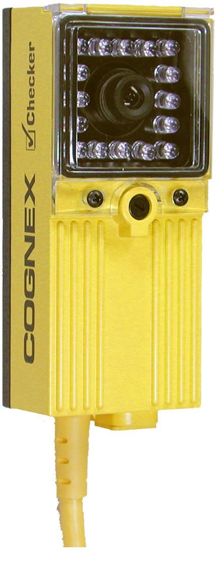
2 About Checker Checker is the sensor. CheckMate is the software that runs on your PC. You use CheckMate to set up Checker. Minimum PC Requirements Microsoft Windows 2000 or Windows XP 400MHz Pentium III CPU 128 MB RAM USB version by 768 Display Physical Description Part Status Indicator (Red LED) Checker Status Indicator (Green LED) On = Run mode 1 Blink/sec = Setup Mode 4 Blinks/sec = Internal Error Focus Adjustment Focus Lock M3 (1.5 mm hex) Power and I/O Cable USB Connector Dimensions and Mounting 53.2 mm 45.9 mm mm mm mm mm mm mm X mounting holes M4x0.70 thread 0.32 deep Getting Started 1 2 Install the CheckMate Software 1 Insert the CheckMate CD-ROM in your PC s CD-ROM drive. The CheckMate install program will start automatically. You must have Administrator rights on your PC to install CheckMate. 2 Follow the on-screen prompts to install CheckMate. Install the Checker Sensor 1 Mount Checker using 3 M4x0.70 screws. The mounting should provide a suitable path to earth ground. Checker comes with three sets of mounting screws of different lengths; choose the correct length for your mounting. 2 Connect your power supply, as shown in the section Connecting Checker. 3 Connect Checker to your PC using supplied USB cable. 4 Connect input and output devices, as shown in the section Connecting Checker.
 Questions and Answers Checker Status Job Setup Steps Controls Filmstrip Filmstrip Control CheckMate always displays a list of questions and answers related to the current state of CheckMate.")
3 3 Start the CheckMate Software Start CheckMate by double-clicking on the CheckMate icon. (The first time that you start CheckMate, it may take a moment before your PC recognizes Checker.) Questions and Answers Checker Status Job Setup Steps Controls Filmstrip Filmstrip Control CheckMate always displays a list of questions and answers related to the current state of CheckMate. For detailed information on how Checker works and how to use CheckMate, click on the button to open the User s Manual. Setting Up Your Job A Checker job contains all of the information that Checker needs to check your part. You set up a Checker job in four simple steps using CheckMate Get Started Create a new job. Enter your line speed and direction. Place a ruler at the same distance from Checker as your part will be, and enter the size of Checker s field of view. If you specify a horizontal machine direction, this size is the distance between the left and right edges of what Checker can see; if you specify a vertical machine direction, the size is the distance between the top and bottom of what Checker can see. Adjust the image brightness and focus Checker on your part. Checker is shipped with its focus unlocked. If you have tightened the focus lock, make sure to loosen it before adjusting the focus. Detect My Part Before Checker inspects your part, it must detect that your part is present. Checker can detect your part in two ways: 1 Checker can detect parts using a Part Finding Sensor. Simply create a Part Finding Sensor and place it over a part feature that Checker can always see. 2 You can use an external photoelectric sensor to tell Checker that the part is present. Checker uses the rising edge of the input signal. If you use both an external photoelectric sensor and a Part Finding Sensor, both the photoelectric sensor and the Part Finding Sensor must indicate that the part is present before Checker will inspect the part. Inspect My Part Create an Inspection Sensor for each part feature that you want to check. The result of an Inspection Sensor can be pass or fail. The results of all Inspection Sensors must be pass for Checker to pass your part. If the result of any Inspection Sensor is fail, Checker will fail your part. Checker provides three types of Inspection Sensors: Brightness Sensors detect bright features; Contrast Sensors detect high-contrast features; and Pattern Sensors detect matching patterns. Brightness Sensor Contrast Sensor Pattern Sensor Brighter More contrast No match Partial match Match To create an Inspection Sensor, click on the feature to check, then adjust the Sensor s threshold so that good parts are above the threshold and bad parts are below it. For Brightness and Contrast sensors, you can adjust the Sensor s range and sensitivity to better distinguish between good and bad parts. You can invert the result of an Inspection Sensor if you need to detect dark features instead of bright features, low-contrast features instead of high-contrast features, or mismatched patterns instead of matching patterns.
4 4 Set up Outputs, Test, and Run Checker has two user-configurable output lines: Output 0 and Output 1. You can configure Checker to send a signal on either line when a part is detected, passed, or failed, or you can disable the output line. Test your job at production speed to make sure that good parts pass and bad parts fail. After testing, adjust the timing of the job s output signals as required. Before disconnecting the PC from Checker, make sure to save your job to Checker and to the PC. To put Checker to work, enter Run mode, disconnect the USB cable, and replace the rubber plug over the USB connector. Connecting Checker Power Voltage: (22-26 VDC) Current: 150 ma max Red Black Part Detect Signal Input Trigger ON: (5 ma) Trigger OFF: < 2 VDC (<1.5 ma) Protection: Opto-isolated, polarity-independent White w/orange stripe Solid orange Example: Connecting a Photoelectric sensor as an External Trigger Output VDC DC common White w/orange stripe Solid orange Photoelectric sensor Output 0 and Output 1 Output 0: Blue & White w/blue Stripe Output 1: Gray & White w/gray Stripe Output: Solid-state switch rated at 100 ma and max Max voltage drop: ma resistive load Max off leakage current: 200 µa Protection: Opto-isolated. Protected from short circuit, overcurrent, and reverse polarity. Method 1: White w/color stripe Solid color Load 100 ma max Method 2: White w/color stripe Load 100 ma max Solid color Example: Connecting to a PLC White w/blue stripe White w/gray stripe Blue Gray Input 0 Input 1 Input 7 Common PLC
 lets you switch between saved Checker jobs and retrain Checker sensors while Checker")
5 GROUND POWER COMMON IN2 IN1 JOB CHANGE JOB SEL3 JOB SEL2 JOB SEL1 JOB SEL0 IN 0 - IN 0 E 1 E 0 OUT 1 - OUT 1 OUT 0 - OUT 0 GROUND POWER PNP NPN YELLOW WHITE/YELLOW ORANGE WHITE/ORANGE LIGHT BLUE BROWN GREY WHITE/GREY BLUE WHITE/BLUE BLACK RED Checker I/O Module The optional Checker I/O Module (CKR-IOBOX-101) lets you switch between saved Checker jobs and retrain Checker sensors while Checker is running. The Checker I/O Module also provides a terminal block that lets you connect other devices to the standard Checker I/O lines. The following figure provides an overview of the Checker I/O Module: Checker I/O Module Checker Job Control and Retrain Lines Checker Input, Output, and Power Lines COGNEX Checker Connect to Checker (color coded) Working Distance and Field of View The distance from Checker s lens cover to your part is the working distance.; the field of view is what Checker can see at that distance. Checker must be able to see enough of your part, and with enough detail, to be able to check it. If the standard lens does not let Checker do this, an inexpensive set of additional lenses is available from Cognex. The following tables show the range of working distances and fields of view for the available lenses: Field of View (Width x Height) Field of View (inches) Working Distance (inches) mm lens 8 mm lens 5.8 mm lens 3.6 mm lens (Standard).46 x x x x x x x x x x x x x x x x x x x x x x x x x x x x 17.9 Field of View (Width x Height) Field of View (mm) 16 mm lens 8 mm lens 5.8 mm lens 3.6 mm lens (Standard) Working Distance (mm) x 9 23 x x x x x x x x x x x x x x x x x x x x x x x x x x x 595 Optimizing Lighting Checker's built-in lighting is optimized for working distances from 3 to 15" (75 mm to 375 mm). Depending on how reflective your part is, you may need to use an external light for longer working distances. You can mount Checker at an angle to reduce highlights and reflections from reflective parts, as shown below: Reflective part Direct Lighting (More Reflections) Reflective part Angled Lighting (Fewer Reflections)
. Any other voltage creates a risk of fire or shock and can damage Checker.")
6 Precautions Observe these precautions when installing Checker to reduce the risk of injury or equipment damage: Do not attempt to adjust Checker s focus when moving parts and/or equipment are present. Use a listed power supply with an output rated 24VDC, at least150ma, and marked Class 2, Limited Power Source (LPS). Any other voltage creates a risk of fire or shock and can damage Checker. Do not install Checker in locations that expose it to environmental hazards such as excessive heat, humidity, impact, vibration, corrosive substances, flammable substances, or static electricity. To reduce the risk of damage or malfunction, route all cables and wires away from high-voltage power sources. Do not attempt to modify Checker. Modifications will void the warranty. Getting Help On-line support is available at support.cognex.com, or you may contact Cognex directly: Region Telephone Direct North America Additional Information support.us@cognex.com Japan support.jp@cognex.com Europe support.eu@cognex.com Cable (power and I/O) 24V power fuse Output fuse 24AWG, 12, pigtail Weight 8.47 oz (240 g) Operating temperature Storage temperature Operating humidity Protection Maximum altitude Shock Vibration 500 milliamp, 60V rated resettable fuse that will recover after an overload is removed. Protects against over voltage and reverse wiring. 200 milliamp, 30v rated resettable fuse that will recover after an overload is removed. Protects each output from over current. 32 to 122 F (0 to 50 C) -22 to 176 F (-30 to 80 C) 0% - 90% non-condensing IP meters 80Gs for 5ms on each axis (per IEC ) 10Gs (10-500Hz) at 100 M/sec 2 / 15mm for 2 hours in each axis (per IEC ) NOTE: This equipment has been tested and found to comply with the limits for a Class A digital device, pursuant to Part 15 of the FCC Rules. These limits are designed to provide reasonable protection against harmful interference when the equipment is operated in a commercial environment. This equipment generates, uses, and can radiate radio frequency energy and, if not installed and used in accordance with the instruction manual, may cause harmful interference to radio communications. Operation of this equipment in a residential area is likely to cause harmful interference in which case the user will be required to correct the interference at his own expense. Copyright 2005 Cognex Corporation All Rights Reserved This document may not be copied in whole or in part, nor transferred to any other media or language, without the written permission of Cognex Corporation. The hardware and portions of the software described in this document may be covered by one or more of the U.S. patents listed on the Cognex web site Other U.S. and foreign patents are pending. Checker, CheckMate, Cognex, and the Cognex logo are trademarks, or registered trademarks, of Cognex Corporation. Microsoft, Windows, and the Windows logo are trademarks, or registered trademarks of Microsoft Corporation in the United States and/or other countries Revision Inches Use this ruler to measure the field of view. Place the ruler the same distance from Checker as your part will be. mm
COGNEX Checker 200 Series Reference
 COGNEX Checker 00 Series Reference Checker 00 Series Products and Accessories Dimensions and Features Getting Started Working Distance and Field of View Adjusting Focus Changing Lenses Mounting Checker
COGNEX. Checker SensorView. Quick Reference Guide
 COGNEX Checker SensorView Quick Reference Guide 890 SensorView 890 Overview SensorView 890 provides self-contained IP-65 touchscreen configuration, control, and monitoring of one or more Checker 4G series
PRODUCT GUIDE. The simple, powerful vision sensors from Cognex. Actual Size
 PRODUCT GUIDE The simple, powerful vision sensors from Cognex Actual Size Powerful Things Come in Small Packages Checker is an all-in-one vision sensor with built-in lighting and a variable working distance,
C h e c k e r V i s i o n S e n s o r s
 C h e c k e r V i s i o n S e n s o r s The Smart Vision Sensor Looking for the easiest, most affordable way to error-proof your manufacturing process? The original Checker vision sensor defined the category,
PRODUCT GUIDE. The simple, powerful vision sensors from Cognex. Actual Size
 PRODUCT GUIDE The simple, powerful vision sensors from Cognex Actual Size Powerful Things Come in Small Packages Checker is an all-in-one vision sensor with built-in lighting and a variable working distance,
Table of Contents. 2 Checker 4G Quick Start Guide Checker 4G Quick Start Guide 3
 Quick Start Guide Table of Contents Table of Contents................................. 3 Checker 4G Accessories.............................. 4 Checker 4G Overview............................... 6 Dimensions,
In-Sight. Micro Series I/O Module Installation Manual
 In-Sight Micro Series I/O Module Installation Manual Legal Notices The software described in this document is furnished under license, and may be used or copied only in accordance with the terms of such
In-Sight 7010C/7200C/7400C
 The following sections list general specifications for the In-Sight vision system. Vision System Specifications Table 3-1: Vision System Specifications Specifications Minimum Firmware Requirement Job/Program
128MB non-volatile flash memory; unlimited storage via remote network device.
 The following sections list general specifications for the In-Sight Micro vision systems. In-Sight Micro Vision System Specifications Table 3-1: In-Sight Micro Vision System Specifications Specifications
E3S-A. Built-in Amplifier Photoelectric Sensor (Medium Size) Ordering Information. Built-in Amplifier Photoelectric Sensors. Horizontal. 7 m.
 Ordering Information. Built-in Amplifier Photoelectric Sensors. Horizontal. 7 m.") Built-in Amplifier (Medium Size) ES-A CSM_ES-A_DS_E Be sure to read Safety Precautions on page 0. Ordering Information Built-in Amplifier s Red light Infrared light Sensing method Appearance Connection
Built-in Amplifier (Medium Size) ES-A CSM_ES-A_DS_E Be sure to read Safety Precautions on page 0. Ordering Information Built-in Amplifier s Red light Infrared light Sensing method Appearance Connection
In-Sight 1400 I/O Expansion Module Installation and Reference Manual
 In-Sight Vision for Industry System DISTRIBUTEUR C ONSEIL DEPUIS 1 9 8 5 In-Sight 1400 I/O Expansion Module Installation and Reference Manual In-Sight 1400 I/O Expansion Module Installation and Reference
E3S-A. Built-in Amplifier Photoelectric Sensor (Medium Size) Ordering Information. Built-in Amplifier Photoelectric Sensors. Horizontal. 7 m.
 Ordering Information. Built-in Amplifier Photoelectric Sensors. Horizontal. 7 m.") Built-in Amplifier (Medium Size) ES-A Be sure to read Safety Precautions on page 0. Ordering Information Built-in Amplifier s Red light Infrared light Sensing method Appearance Connection method Sensing
Built-in Amplifier (Medium Size) ES-A Be sure to read Safety Precautions on page 0. Ordering Information Built-in Amplifier s Red light Infrared light Sensing method Appearance Connection method Sensing
SMI-100 Stack Monitoring Interface Installation & Operation Manual
 SMI-100 Stack Monitoring Interface Installation & Operation Manual Aquion Energy, Inc. 32 39th Street Pittsburgh, PA 15201 +1 412.904.6400 aquionenergy.com AQ-OP-00015_C 12.23.16 2016 Aquion Energy, Inc.
USER GUIDE. AXIS T8120 Midspan 15 W 1-port ENGLISH
 USER GUIDE AXIS T8120 Midspan 15 W 1-port ENGLISH Legal Considerations Video and audio surveillance can be prohibited by laws that vary from country to country. Check the laws in your local region before
onlinecomponents.com
 R General-Purpose Fiber-optic Sensor Compact Limit Switch Style with Universal Supply H FET output allows for solid state switching of AC or DC H Universal AC/DC power supply H Choose cable or connector
General-Purpose Photoelectric Sensor
 General-Purpose Photoelectric Sensor Compact Limit Switch Style with Universal Supply FET output allows for solid state switching of AC or DC Universal AC/DC power supply Choose cable or connector types
EXPRESS. Assembly Manual & User Guide
 EXPRESS Assembly Manual & User Guide CONTENTS Introduction... 1 1.1 Minimum System Requirements 1.2 Drive Compatibility 1.3 Package Contents 1.4 Enclosure Features 1.5 About This Manual Device Setup...
Artisan Technology Group is your source for quality new and certified-used/pre-owned equipment
 Artisan Technology Group is your source for quality new and certified-used/pre-owned equipment FAST SHIPPING AND DELIVERY TENS OF THOUSANDS OF IN-STOCK ITEMS EQUIPMENT DEMOS HUNDREDS OF MANUFACTURERS SUPPORTED
I/O Expansion Module Installation & Reference
 Overview The In-Sight vision sensor supports up to ten discrete inputs and ten discrete outputs. Two inputs and two outputs are built-in to the In-Sight processor. The remaining eight inputs and outputs
Mini Photoelectric Sensor
 Mini Photoelectric Sensor High cost-performance Mini Photoelectric Sensor Saves Installation Space and Wiring Effort and Detects Minute Sensing Objects Pin-point beam (1 to 2-mm dia.) makes it possible
BGS (at min. setting) BGS (at max. setting)
 BGS (at max. setting)") Compact Photoelectric Sensor with Built-in Amplifier EZ-LS CSM_EZ-LS_DS_E_7_ Distance-settable Sensor Unaffected by Workpiece Color and Background Distance-settable triangulation model unaffected by color.
Compact Photoelectric Sensor with Built-in Amplifier EZ-LS CSM_EZ-LS_DS_E_7_ Distance-settable Sensor Unaffected by Workpiece Color and Background Distance-settable triangulation model unaffected by color.
Sensing method Appearance Connection method Sensing distance Part number NPN output PNP output Through-beam Prewired (2 m) E3Z-T61A E3Z-T81A 10 m
 E3Z-T61A E3Z-T81A 10 m") Through-Beam Sensor with Visible Red LED Visible Beam Allows Visual Confirmation of the Detection Spot, for Easy Installation and Maintenance Built-in amplifier Mutual interference protection filter included
Through-Beam Sensor with Visible Red LED Visible Beam Allows Visual Confirmation of the Detection Spot, for Easy Installation and Maintenance Built-in amplifier Mutual interference protection filter included
NPN output PNP output Cord connection Cord length: 2 m Through-beam 7 m Light-ON. 2 m. (selectable by wiring) Diffuse reflective 0.
 Diffuse reflective 0.") Built-in Amplifier Photoelectric Sensor E3V3 Easy-to-use, Low-cost Photoelectric Sensor Incorporating s that can be clearly seen from a distance. A series of models with an M8 metal junction connector
Built-in Amplifier Photoelectric Sensor E3V3 Easy-to-use, Low-cost Photoelectric Sensor Incorporating s that can be clearly seen from a distance. A series of models with an M8 metal junction connector
Camera A14 and A34 Dome Camera
 Camera A14 and A34 Dome Camera Quick Start Guide Thank you for purchasing our product. If there are any questions, or requests, please do not hesitate to contact the dealer. About This Manual: This manual
Perle MCR200 Installation Guide
 Perle MCR200 Installation Guide P/N 5500322-10 Introduction The Perle MCR200 Chassis is a 2 slot chassis able to accommodate up to 2 Perle Media Converter modules or 1 Media Converter Module and an MCR-MGT
Light ON 5m. * Light ON. 2.5m (3m) Light ON. (5m)
 Light ON. (5m)") All voltage photoelectric sensors Built-in amplifier accepts wide supply voltage range. Slim, space-saving construction measures only x x 7.4 mm. s with long life expectancy and high switching capacity
All voltage photoelectric sensors Built-in amplifier accepts wide supply voltage range. Slim, space-saving construction measures only x x 7.4 mm. s with long life expectancy and high switching capacity
Operating instructions. Switching amplifier DN0210 DN / / 2015
 Operating instructions Switching amplifier DN0210 DN0220 UK 80011079 / 00 01 / 2015 Contents 1 Preliminary note...4 1.1 Symbols used...4 1.2 Warning signs used...4 2 Safety instructions...5 2.1 General...5
When any of the following symbols appear, read the associated information carefully. Symbol Meaning Description
 Uni-I/O Wide Modules Installation Guide UID-W1616R, UID-W1616T Uni-I/O Wide is a family of Input/Output modules that are compatible with the UniStream control platform. Wide Modules are 1.5 times as wide
System D I S T R I B U T E U R C O N S E I L D E P U I S vision sensors PRODUCT SPECIFICATIONS AND DRAWINGS
 System D I S T R I B U T E U R C O N S E I L D E P U I S 1 9 8 5 vision sensors PRODUCT SPECIFICATIONS AND DRAWINGS 2006-1 specifications In-Sight 5000, 5100, 5400, 5400S, 5400C, 5401, and 5403 Memory
Color Mark Photoelectric Sensor E3S-VS
 Sensing Supply voltage Output 12 to 80 ma, with 1.5 to 4 ma constant current source; 1.2 cm, 5 cm 100 ma, Color Mark Photoelectric Sensor Small Color Mark Sensor With Built-In DC Amplifier Fast, 1 ms maximum
AURA SSD FOR MAC PRO. Installation Guide
 AURA SSD FOR MAC PRO Installation Guide CONTENTS Introduction... 1 1.1 System Requirements 1.2 Package Contents 1.3 About This Manual Installation... 2 2.1 Preparing the Mac Pro 2.2 Installing the Aura
SUPERSLIM. Assembly Manual & User Guide
 SUPERSLIM Assembly Manual & User Guide PACKAGE CONTENTS A. optical drive enclosure B. USB Y type cable (Standard-A to mini-b) C. Collared Phillips screws (3) D. Rubber foot with adhesive backing E. Fully
ML20 Series Long-Range Miniature Sensors
 Diffuse Mode See pages 486-487 Features: Cross-talk immune for 2 units Divergent beam versions available Sensing Ranges: mm, 1 m Output: NPN, PNP Thru-Beam Mode See page 489 Features: Alignment in lens
DRIVE DOCK. User Guide
 DRIVE DOCK User Guide CONTENTS INTRODUCTION 1.1 Minimum System Requirements...1 1.1.1 Apple Mac Requirements 1.1.2 PC Requirements 1.1.3 Supported Drives 1.2 Package Contents...1 1.3 About This Manual...1
ENVOY PRO. Assembly Manual & User Guide
 ENVOY PRO Assembly Manual & User Guide TABLE OF CONTENTS INTRODUCTION... 1 1.1 MINIMUM SYSTEM REQUIREMENTS 1.1.1 Apple Mac Requirements 1.1.2 PC Requirements 1.2 PACKAGE CONTENTS 1.3 ABOUT THIS MANUAL
Optimum sensing capability for LCD manufacturing
 SENSORS FOR Glass Substrate Detection Sensor Amplifier-separated FX-301-F FT-F9 FD-F7 EX-F70/F60 HD-T1 M FD-L3 Reliable detection of glass substrates Its unique optical system enables detection of transparent
OPERATING INSTRUCTION
 OPERATING INSTRUCTION AUTORANGING MULTIMETER MAX Ω F C 10A MAX every 15 min. COM V SAFETY INFORMATION The following safety information must be observed to insure maximum personal safety during the operation
OWC Mercury Pro Optical ASSEMBLY MANUAL & USER GUIDE
 OWC Mercury Pro Optical ASSEMBLY MANUAL & USER GUIDE Copyright 2015 Other World Computing All Rights Reserved. Other World Computing s Limited Warranty is not transferable and subject to limitations. TABLE
MERCURY PRO. Assembly Manual & User Guide
 MERCURY PRO Assembly Manual & User Guide CONTENTS Introduction... 1 1.1 Minimum System Requirements 1.1.1 Apple Mac Requirements 1.1.2 PC Requirements 1.1.3 Supported Optical Drives 1.2 Package Contents
the Interactive Catalog
 Interactive Catalog Supplements Catalog PDFs If you need detailed product information, or help choosing the right product for your application, see our Interactive Catalog Use the Interactive Catalog to
RING LIGHT. LED Strobe Indicator ON = Light Active Green Indicator LED
 R80 Series RING LIGHT product introduction The all metal construction of the Series of lights provides a small particle resistant and all around durable light. Its simple plug and play 5 Pin M12 connector
When any of the following symbols appear, read the associated information carefully. Symbol Meaning Description
 Uni-I/O Modules Installation Guide UID-0808THS Uni-I/O is a family of Input/Output modules that are compatible with the UniStream control platform. This guide provides basic installation information for
Envoy Pro ASSEMBLY MANUAL & USER GUIDE
 Envoy Pro ASSEMBLY MANUAL & USER GUIDE TABLE OF CONTENTS INTRODUCTION... 1 1.1 MINIMUM SYSTEM REQUIREMENTS 1.1.1 Apple Mac Requirements 1.1.2 PC Requirements 1.2 PACKAGE CONTENTS 1.3 ABOUT THIS MANUAL
PSW-002. Fiber Optic Polarization Switch. User Guide
 PSW-002 Fiber Optic Polarization Switch User Guide Version: 1.1 Date: June 30, 2015 General Photonics Corporation is located in Chino California. For more information visit the company's website at: www.generalphotonics.com
Suitable for detecting transparent films or transparent bottles
 Ultrasonic Sensor Suitable for detecting transparent films or transparent bottles Reliable detection of transparent objects The sensor reliably detects transparent films or transparent objects. Only 16
When any of the following symbols appear, read the associated information carefully. Symbol Meaning Description
 Uni-I/O Modules Installation Guide UID-0808R, UID-0808T, UID-1600,UID-0016R, UID-0016T Uni-I/O is a family of Input/Output modules that are compatible with the UniStream control platform. This guide provides
Ultra-small U-shaped Micro Photoelectric Sensor. Extremely small size enables space saving!! 12 mm in
 1 Ultra-small Micro Photoelectric PM- SERIES Related Information General terms and conditions... F-17 Glossary of terms / General precautions... P.19~ / P.10 Amplifier Built-in selection guide... P.1~
4100/ VDC Converter Installation Instructions
 4100/4120-0156 8 VDC Converter Installation Instructions Introduction This publication describes the installation procedure for the 8 VDC Converter. Related Documentation Field Wiring Diagram for 4100
PM-24 SERIES. Ultra-small U-shaped Micro Photoelectric Sensor. Extremely small size enables space saving!! ( ) Equipped with two independent outputs
 Equipped with two independent outputs") 19 Ultra-small Micro Photoelectric Sensor PM- SERIES Related Information General terms and conditions...p.1 Glossary of terms / General precautions...p.98~ / P.98~ Amplifier Built-in Sensor selection guide...p.11~
19 Ultra-small Micro Photoelectric Sensor PM- SERIES Related Information General terms and conditions...p.1 Glossary of terms / General precautions...p.98~ / P.98~ Amplifier Built-in Sensor selection guide...p.11~
OWC Mercury On-The-Go Pro USER GUIDE
 OWC Mercury On-The-Go Pro USER GUIDE TABLE OF CONTENTS 1. INTRODUCTION... 1 1.1 MINIMUM SYSTEM REQUIREMENTS 1.1.1 Apple Mac Requirements 1.1.2 PC Requirements 1.2 PACKAGE CONTENTS 1.3 ABOUT THIS MANUAL
Innovative Circuit Technology Ltd.
 Innovative Circuit Technology Ltd. Pro Series DC Power Supply INSTRUCTION MANUAL 855-343-001 Models: ICT690-12S/ICT690-12SB ICT690-24S/ICT690-24SB ICT690-48S/ICT690-48SB ICT1190-12S/ICT1190-12SB ICT1190-24S/ICT1190-24SB
The World s Smallest TOF Sensor lineup with analog output type
 7 New model TOF type with built-in digital panel series The World s Smallest TOF Sensor lineup with analog output type Analog output type and -control-output type The world s smallest TOF sensor Built-in
Toll Free: Tel: Fax:
 Toll Free: 1-888-865-6888 Tel: 510-226-8368 Fax: 510-226-8968 Email: sales@rackmountmart.com User Manual LCDK 1070 DVI-D KVM Legal Information First English printing, October 2002 Information in this document
INSTALLATION INSTRUCTIONS
 INSTALLATION INSTRUCTIONS Adaptor Model No. CZ-CFUNC1U For your safety Read the following instructions carefully, and carry out secure installation and electrical work. The precautions given in this manual
Sensors. Compact: S60 Series. Compact: S60 Series. Multifunction Optoelectronic Sensors
 Multifunction Optoelectronic Long operating distance Sensitivity adjustment Independent NO-NC outputs M12 connection with standard NPN or PNP configuration The S60 sensors have a sensitivity adjustment
Calibration Kit. General Instructions. Table of Contents. System Requirements
 Calibration Kit These instructions provide information on the installation, connection and operation of the Calibration Kit for use with SOR 805 Series pressure products, specifically the 805PT and 805QS.
C5 Series Stainless Steel Photoelectric
 C5 Series Stainless Steel Photoelectric Part Number Sensing Range M5 (5 mm) stainless steel - DC 14 models available Diffuse and through-beam styles Long operating distances Compact stainless steel housing
DRIVE DOCK. User Guide
 DRIVE DOCK User Guide CONTENTS INTRODUCTION 1.1 Minimum System Requirements...1 1.1.1 Apple Mac Requirements 1.1.2 PC Requirements 1.1.3 Supported Drives 1.2 Package Contents...1 1.3 About This Manual...1
S8VE (60/90/120/180/240-W Models)
") Switch Mode Power Supply S8VE (60/90/120/180/240-W Models) CSM_S8VE_DS_E_1_1 60/90/120/180/240-W Models Improved Versions of Standard-type Power Supplies without Indication Monitor. Safety standards: UL508/60950-1,
Switch Mode Power Supply S8VE (60/90/120/180/240-W Models) CSM_S8VE_DS_E_1_1 60/90/120/180/240-W Models Improved Versions of Standard-type Power Supplies without Indication Monitor. Safety standards: UL508/60950-1,
ENVOY. Assembly Manual & User Guide
 ENVOY Assembly Manual & User Guide CONTENTS Introduction...1 1.1 Minimum System Requirements 1.2 Package Contents 1.3 About This Manual 1.4 Port View 1.5 LED Indicator Device Setup...3 2.1 Assembly Support
XUK8TAKSMM12 photo-electric sensor - XUK - diffuse - Sn 5m 1Q auto PNP/NPN
 Characteristics photo-electric sensor - XUK - diffuse - Sn 5m 1Q auto PNP/NPN Complementary Enclosure material Lens material Maximum sensing distance Output type Add on input Wire insulation material Status
Mercury Helios ASSEMBLY MANUAL & USER GUIDE
 Mercury Helios ASSEMBLY MANUAL & USER GUIDE TABLE OF CONTENTS INTRODUCTION...1 1.1 MINIMUM SYSTEM REQUIREMENTS 1.1.1 Apple Mac Requirements 1.1.2 PC Requirements 1.1.3 Supported PCIe Cards NOTE: Boot Camp
V E1B Snap-in I/O Module
 V200-18-E1B Snap-in I/O Module The V200-18-E1B plugs directly into the back of compatible Unitronics OPLCs, creating a selfcontained PLC unit with a local I/O configuration. Features 16 isolated digital
See instructions to download and install the latest version of LinkBoxLON and the user's manual at
 Safety Instructions WARNING Follow carefully this safety and installation instructions. Improper work may lead to serious harmful for your health and also may damage seriously the IntesisBox and/or any
5 B&W Rear View System Camera
 5 B&W Rear View System Camera Instruction Manual MODEL: CA453 www.lorexcctv.com Copyright 2007 LOREX Technology Inc. Thank you for purchasing the Lorex 5 Black & White Rear View System Camera. This system
Oil-resistive, Long-range Photoelectric Sensor with Metal Housing
 Oil-resistive, Long-range with Metal Housing ES-C Water- and Oil-resistive with Metal Housing Used for Long-range Sensing Satisfies the water- and oil-resistive requirements and safe enough for use in
DFP Series Fiber Photoelectric Amplifiers
 DFP Series Fiber electric Amplifiers Part Number Compact rectangular plastic DIN-rail mount- DC models available DIN-rail mounting 12-turn potentiometer sensitivity setting with illuminated scale NPN or
SAFETY, ENVIRONMENTAL, AND REGULATORY INFORMATION. NI CompactDAQ Four-Slot Controller with Quad-Core Processor
 SAFETY, ENVIRONMENTAL, AND REGULATORY INFORMATION NI cdaq -9136 NI CompactDAQ Four-Slot Controller with Quad-Core Processor This document includes compliance precautions and connection information for
Mid-span 802.3af PoE Injector. Installation Guide KPOE-100
 Mid-span 802.3af PoE Injector Installation Guide KPOE-100 Doc. 070521 1 (C) 2005 KTI Networks Inc. All rights reserved. No part of this documentation may be reproduced in any form or by any means or used
TABLE OF CONTENTS INTRODUCTION...1 DEVICE SETUP...4 SUPPORT RESOURCES...9
 TABLE OF CONTENTS INTRODUCTION...1 1.1 Minimum System Requirements 1.2 Package Contents 1.3 About This Manual 1.4 Rear View 1.4.1 Rear Features 1.5 Usage Notes DEVICE SETUP...4 2.1 Quick Start 2.2 Assembly
ML17 Series Tru-Vue TM Sensors
 ML7 Series Tru-Vue TM Sensors Diffuse Mode with Background Suppression See page 44 Features: Ver low color sensitivit Tamper-proof housing with no eternal adjustments Sensing Range: 5 mm Output: 4-in-
RING LIGHT. ON = Light Rest (LED inactive) OFF = LED/Light Ready Green Indicator LED
 OFF = LED/Light Ready Green Indicator LED") product introduction ODR130-16 Series RING LIGHT OverDrive The ODR130-16 Series ring light features an Overdrive driver with NPN or PNP signal options. The all metal construction of the Ring Light Series
product introduction ODR130-16 Series RING LIGHT OverDrive The ODR130-16 Series ring light features an Overdrive driver with NPN or PNP signal options. The all metal construction of the Ring Light Series
3-Phase, Dual-Input 6-Slot Power Supply System STARTUP GUIDE
 3-Phase, Dual-Input 6-Slot Power Supply System STARTUP GUIDE -ST-01 Page 1 of 10 November 2016 2016 Copyright Lite-On Technology Corporation ALL RIGHTS RESERVED. Lite-On is a trademark of Lite-On Technology
em4 Accessories Digital expansions
 em4 Accessories Digital expansions Up to two digital / analog expansions can be added to the em4 nanoplc to expand up to 46 I/Os 6 digital / analog configurable inputs (0-10 VDC, 0-28.8 VDC, Potentiometer)
V8-80HS-1 SERIES OF HIGH-SPEED MOTORIZED ZOOM LENSES
 X684 V8-80HS-1 SERIES OF HIGH-SPEED MOTORIZED ZOOM LENSES Copyright 2000 Vicon Industries Inc. All rights reserved. Product specifications subject to change without notice. Vicon and its logo are registered
Industrial 5-Port Fast Ethernet Switches with SFP Slot and optional 4 PoE PSE Ports. Basic Model: KSD-541 PoE Model: KSD-541-P. Installation Guide
 Industrial 5-Port Fast Ethernet Switches with SFP Slot and optional 4 PoE PSE Ports Basic Model: KSD-541 PoE Model: KSD-541-P Installation Guide DOC.080104-1- (C) 2008 KTI Networks Inc. All rights reserved.
IO-DI8-TO8, IO-DI8-TO8-L I/O Expansion Modules 8 Inputs, 8 Outputs
 IO-DI8-TO8, IO-DI8-TO8-L I/O Expansion Modules 8 Inputs, 8 Outputs The IO-DI8-TO8 and IO-DI8-TO8-L are I/O expansion modules that can be used in conjunction with specific Unitronics OPLC controllers. The
Satellite INSTALLATION GUIDE
 N3 Satellite INSTALLATION GUIDE ! WARNING! Shock Hazard. May result in serious injury or death. Turn power OFF at circuit breaker or remove fuse. Damage to this product caused by wiring with power on voids
S-14 S-14. Compact Digital Multimeter. Compact Digital Multimeter
 S-14 Compact Digital Multimeter S-14 Compact Digital Multimeter SAFETY INFORMATION The following safety information must be observed to insure maximum personal safety during the operation at this meter
Operating instructions. Speed monitor D / / 2014
 Operating instructions Speed monitor D200 80005257 / 00 05 / 2014 Contents 1 Preliminary note...4 1.1 Symbols used...4 1.2 Warning signs used...4 2 Safety instructions...5 2.1 General...5 2.2 Target group...5
Installation Manual Rev D MiniProx Readers - Wiegand 5365B and Clock and Data 5368B
 Installation Manual - 5365-902 Rev D MiniProx Readers - Wiegand 5365B and Clock and Data 5368B Web page, E-mail - www.prox.com MiniProx Reader Installation Manual 5365-902 REV D 1 of 7 MiniProx Reader
TB21. NO - Relay. Relay. Common - Relay. NC - Relay. Input J23. Ground TB22 TB23. NO - Relay Common - Relay NC - Relay Input Ground.
 NXT x.0 Wiring and Layout Diagrams. NXT-x I/O Module Shielded CAT- Cabling Shielded -Conductor Cabling total cable length 00 feet max (0 m) Brown/Green/Orange w/o Stripe Brown/Green/Orange with Stripe
IB080QM65VA3 Part Number
 Inductive Proximity Switch with increased Switching Distance IB080QM65VA3 Part Number Technical Data Inductive Data Switching Distance 8 mm Correction Factors V2A/CuZn/Al 0,93/0,40/0,36 quasi-flush A/B/C/D
OWC Mercury Helios 2 ASSEMBLY MANUAL & USER GUIDE
 OWC Mercury Helios 2 ASSEMBLY MANUAL & USER GUIDE TABLE OF CONTENTS 1. INTRODUCTION...1 1.1 MINIMUM SYSTEM REQUIREMENTS 1.1.1 Apple Mac Requirements 1.1.2 PC Requirements 1.1.3 Supported PCIe Cards 1.2
DM-918 OPERATIONS MANUAL AUTORANGING MULTIMETER
 DM-918 OPERATIONS MANUAL AUTORANGING MULTIMETER SAFETY INFORMATION The following safety information must be observed to ensure maximum personal safety during the operation of this meter: This meter is
DATA DOUBLER. Apple Mac mini (2009)
") DATA DOUBLER Apple Mac mini (2009) TABLE OF CONTENTS Introduction... 1 1.1 Hardware Compatibility 1.1.1 Host Computer Compatibility 1.1.2 Drive Compatibility 1.2 Package Contents 1.3 About This Manual
DATA DOUBLER Apple Mac mini (2009) TABLE OF CONTENTS Introduction... 1 1.1 Hardware Compatibility 1.1.1 Host Computer Compatibility 1.1.2 Drive Compatibility 1.2 Package Contents 1.3 About This Manual
EC07 EC63. Compatible actuators: ERL2 ESD2. How to order EC 07 B. Series. B Installation. method
 Controller EC07 EC63 Compatible actuators: ERL ESD Features Compact, light weight and thin (Body width 35mm) Can be set without manual Perfect installation compatibility with actuator PC software available
Installation- and Operating instructions for CU Ethernet Controller with USB Input. Version: 1.4 Date:
 Installation- and Operating instructions for CU8880-0010 Ethernet Controller with USB Input Version: 1.4 Date: 2018-04-12 Table of contents Table of contents 1. 2. 3. 4. 5. General instructions 2 Notes
Ground Master Monitor Installation, Operation and Maintenance
 USER GUIDE TB-9078 Ground Master Monitor Installation, Operation and Maintenance Made in the United States of America The Ground Master Monitor and its accessories are available as the following item numbers:
FUSION MS-RA70/MS-RA70N Installation Instructions
 FUSION MS-RA70/MS-RA70N Installation Instructions Important Safety Information WARNING Failure to follow these warnings and cautions could result in personal injury, damage to the vessel, or poor product
USB-C DOCK USER GUIDE
 USB-C DOCK USER GUIDE CONTENTS INTRODUCTION...1 1.1 Minimum System Requirements 1.2 Package Contents 1.3 About This Manual 1.4 Front View 1.5 Rear View SUPPORT RESOURCES...4 2.1 Connection 2.2 Usage Notes
V E2B Snap-in I/O Module
 V200-18-E2B Snap-in I/O Module The V200-18-E2B plugs directly into the back of compatible Unitronics OPLCs, creating a selfcontained PLC unit with a local I/O configuration. Features 16 isolated digital
DeltaV Bulk Power Supplies
 DeltaV Distributed Control System Product Data Sheet DeltaV Bulk Power Supplies DeltaV 5 A, 10A, 20 A, 40 A Bulk Power Supplies. DeltaV 20 A, 40 A and 80 A Bulk Power Supply Redundancy Modules. Easy to
Operating instructions Programming and display unit PP / / 2010
 Operating instructions Programming and display unit PP2001 704795 / 00 05 / 2010 Contents 1 Preliminary note3 1.1 Explanation of symbols 3 2 Safety instructions 3 3 Items supplied 4 4 Functions and features
When any of the following symbols appear, read the associated information carefully. Symbol Meaning Description
 Uni-I/O Wide Modules Installation Guide UIS-WCB1 Uni-I/O Wide is a family of Input/Output modules that are compatible with the UniStream control platform. Wide Modules are 1.5 times as wide as Uni-I/O
THUNDERBAY 4 MINI. Assembly Manual & User Guide
 THUNDERBAY 4 MINI Assembly Manual & User Guide CONTENTS INTRODUCTION 1.1 Minimum System Requirements...1 1.1.1 Apple Mac Requirements 1.1.2 PC Requirements 1.1.3 Supported Drives 1.2 Package Contents...1
Voyager S3. User guide
 Voyager S3 User guide TABLE OF CONTENTS INTRODUCTION...1 1.1 Minimum System Requirements 1.1.1 Apple Mac Requirements 1.1.2 PC Requirements 1.1.3 Supported Drives 1.2 Package Contents 1.3 About This Guide
BS 181 SINGLE CHANNEL POWER SUPPLY USER MANUAL
 BS 181 SINGLE CHANNEL POWER SUPPLY USER MANUAL August 2016 This product is designed and manufactured by: ASL Intercom B.V. Zonnebaan 42 3542 EG Utrecht The Netherlands Phone: +31 (0)30 2411901 Fax: +31
NA1-5. Ultra-slim Body 25mm Beam Pitch Area Sensor. Even a Slim Hand Is Detected by the 25mm Pitch Beam Curtain AREA SENSORS.
 Ultra-slim Body 2mm Pitch Area Sensor mm Thick: /2 of Conventional Model It fits into a small space, without obstructing normal operation. Clearly Visible Job Indicator Both the emitter and the receiver
DeltaV Bulk Power Supplies
 DeltaV Distributed Control System Product Data Sheet DeltaV Bulk Power Supplies DeltaV 5 A, 10A, 20 A, 40 A Bulk Power Supplies. DeltaV 20 A, 40 A and 80 A Bulk Power Supply Redundancy Modules. Easy to