Backup camera svstem for Nissan NV vans L..JSAFETY A Safe Fleet Brand
|
|
|
- Barnard Powell
- 5 years ago
- Views:
Transcription


1 Backup camera svstem for Nissan NV vans Product Manual/ Installation Instructions Rear View Camera Systems Model# RVS r7 REARVIEW L..JSAFETY Rear View Safety Inc A Safe Fleet Brand


2 What s in the Box? COLOR WEATHERPROOF THIRD-BRAKE-LIGHT CAMERA 7" TFT LCD DIGITAL CLIP-ON MIRROR MONITOR 3 CHANNEL MULTIPLEXER CONTROL UNIT 33 CAMERA CABLE REMOTE CONTROL POWER CONNECTION WIRE DOUBLE RCA + POWER CONVERTER (TO CONNECT EXTERNAL AUDIO, VIDEO AND POWER) SCREW KIT FOR INSTALLATION
3 Table of Contents Introduction...4 Safety Information Before Beginning Installation...8 Installation Guide...9 Wiring Camera & Monitor Installation Tips Installation Diagram...14 Installing the Monitor...15 Monitor Operation Splicing...17 Positioning Multiplexer...19 Monitor Dimensions...20 Monitor Specifications...21 Camera Dimensions...22 Camera Specifications...23 Troubleshooting...24 Warranty...25 Disclaimer
4 Introduction Congratulations on purchasing a Rear View Backup Camera System! With this manual you will be able to properly install and operate the unit. Please read all of the installation instructions carefully before installing the product. Improper installation will void manufacturer s warranty. The Backup Camera System is intended to be installed as a supplement aid to your standard rear view mirror that already exists in your vehicle. The Backup Camera System should not be used as a substitute for the standard rear view mirror or for any other mirror that exists in your vehicle. In some jurisdictions, it is unlawful for a person to drive a motor vehicle equipped with a TV viewer or screen located forward of the back of the driver s seat or in any location that is visible, directly or indirectly, to the driver while operating the vehicle. 4 REAR VIEW SAFETY
5 Safety Information Please read the entire manual and follow the instructions and warnings carefully. Failure to do so can cause serious damage and/or injury, including loss of life. Be sure to obey all applicable local traffic and motor vehicle regulations as it pertains to this product. Improper installation will void manufacturer s warranty. USAGE The Rear View Camera System is designed to help the driver safely detect people and/or objects helping to avoid damage or injury. However, you the driver, must use it properly. Use of this system is not a substitute for safe, proper or legal driving. Never back up while looking at the monitor alone. You should always check behind and around the vehicle when backing up, in the same way as you would if the vehicle did not have the Rear View Reverse With Confidence Camera System. If you back up while looking only at the monitor, you may cause damage or injury. Always back up slowly. The Rear View Camera System is not intended for use during exstensive back-up maneuvers or backing into cross traffic or pedestrian walkways. Please, always remember, the area displayed by the Rear View Camera System is limited. It does not display the entire panorama that is behind you. 5
6 Safety Information INSTALLATION Electric shock or product malfunction may occur if this product is installed incorrectly. Use this product within the voltage range specified. Failure to do so can cause electronic shock or product malfunction. Take special care when cleaning the monitor. Make sure to firmly affix the product before use. If smoke or a burning smell is detected, disconnect the system immediately. Where the power cable may touch a metal case, cover the cable with a friction tape. A short circuit or disconnected wire may cause a fire. While installing the Rear View System be careful with the wire positioning in order to avoid wire damage. The Rear View System should only be used when the vehicle is in reverse. Do not watch movies or operate the monitor while driving; as it may cause an accident. Do not install the monitor where it may obstruct drivers view or obstruct an air bag device. Dropping the unit may cause possible mechanical failure. 6 REAR VIEW SAFETY
7 Safety Information If you have questions about this product, contact: Customer Service: Rear View Safety 1797 Atlantic Avenue Brooklyn, NY Tel: IN NO EVENT SHALL SELLER OR MANUFACTURER BE LIABLE FOR ANY DIRECT OR CONSEQUENTIAL DAMAGES OF ANY NATURE, OR LOSSES OR EXPENSES RESULTING FROM ANY DEFECTIVE PRODUCT OR THE USE OF ANY PRODUCT. Reverse With Confidence 7
8 Before You Begin Installation Before drilling please check that no cable or wiring is on the other side of the wall. Please clamp all wires securely to reduce the possibility of them being damaged while vehicle is in use. Keep all cables away from hot or moving parts and electrical noisy components. We recommend doing a benchmark test before installation to insure that all components are working properly. Step 1: Choose the monitor and camera locations. Step 2: Install all cables in vehicle, when necessary a 0.8 (20mm) hole should be drilled for passing camera cable through vehicles walls. Install split grommets where applicable. Step 3: Once all cables and wiring have been properly routed, perform a system function test by temporarily connecting the system. If the system seems to not be operating properly see troubleshooting (page 22). 8 REAR VIEW SAFETY
9 Installation Guide Camera 1. Attach camera bracket close to rear marker lights, centered on vehicle. 2. Attach camera to bracket using screws provided and adjust the angle. Cable 1. Be sure to position the cable properly. The aviation camera cable uses aircraft grade connectors which means the camera cable can be exposed to all weather elements, do not run the cable over sharp edges, do not kink the cable and keep away from HOT and rotating parts. 2. Fasten all cable and secure all excess cable. Monitor 1. The Mirror Monitor attaches to the existing rear view mirror in vehicle with the pressurized clips on the back of the monitor. 2. Attach monitor to existing mirror, and adjust mounting angle to allow optimum driver viewing comfort. (see figure 1.1 on page 12). Reverse With Confidence 9
10 Wiring Camera & Monitor When installing a ONE (1) camera setup, connect camera extension cable from the rear view camera to port labeled backup (most systems port #3) Connect red 12V+ wire to ignition power source and black wire 12V- to chassis ground. Do not use white and yellow wires. The blue wire is the REVERSE trigger wire. In typical rear-view installations, connecting this wire to the vehicle s backup light circuit will activate the rear-view image whenever the vehicle shifts into reverse. Before drilling, be sure no cable or wire is on the other side. Feed as much cable as possible into vehicle & clamp securely. This reduces the possibility of cable being hooked or snagged. Camera: Drill a 20mm (0.8in) diameter hole into vehicle body near the camera and bracket. Insert camera cable into vehicle (be careful not to kink cable) and fit grommet into hole. Apply sealant around grommet to increase resistance to water penetration. Connect camera to the camera extension cable which runs inside the vehicle. The camera system can be wired to be powered ON the entire time the vehicle is on. This is typical in RV and some commercial applications. The camera and monitor can always be activated by manually pushing the power button on monitor. This is in addition to utilizing the positive triggers. Note: If connecting power directly to battery, the camera is always ON and therefore can drain battery. Therefore it is recommended to connect power to an ignition switched accessory power source. 10 REAR VIEW SAFETY
11 Wiring Camera & Monitor Audio works on two ports of multiplexer and positive triggers must be triggered for audio to operate. These are port #3 labeled backup (blue trigger) and port #2 labeled DVD (white trigger). When installing a TWO (2) camera setup, use ports #3 and #2 and use positive triggers Blue and White. There is a built-in voltage regulator for our systems which can handle volts. Real F To automatically have camera and monitor turn ON when vehicle activates, simply twist BLUE positive trigger 12V+ to Red Power line 12V+ and wire to ignition power which can be an accessory switch/fuse line and black wire 12V- to chassis ground. F Infrared technology built into camera IRs are activated automatically according to the Reverse With Confidence consumption is 10 to 30 Volts. When installing all THREE (3) cameras, use all three ports and connect all positive triggers to appropriate connections. To activate grid lines connect the blue trigger to a power source. If you want the grid lines to be on when reversing, connect the blue trigger to reverse power. If you want the grid lines to be on all the time connect the blue trigger to a constant power. lighting conditions. F When using the postive trigger functions (blue, yellow & white wires) each trigger function needs to work on a seperate 12V+ source i.e. the Yellow and White wires can be wired to a turn signal circuit etc. F Grid lines function can be turned on/off by manually from menu. (See page 14) 11
12 Installation Tips Sprinter Chassis third brake light camera RVS Systems Pro Tips for Sprinter Chassis third brake light camera installation: 1. Always use our supplied camera cable from the rear to the monitor 2. You will find clean power hook-ups under the driver seat area to power our RVS monitor offerings. Determine positive and negative hook-ups are correct 3. Our multiplex box can accept (2) more cameras and has default wires for turn signals if required. Under the driver seat is the best place for the left and right turn signal default hook up 4. There are two approved locations to pick up the reverse wire. A. The BEST place to tap the reverse trigger is located in the rear of the coach in the rear pillar at the bottom grey plastic cover. There is a 4 pin connection for the tail lights. Strip off a little insulation of the reverse wire, attach a reverse wire, then loom that reverse wire along our camera cable to the multiplex box B. If you are not using our monitor with multiplex box, you can open the hood of the Sprinter, take the cover off the fuse block and get the reverse trigger off the blue wire. 12 REAR VIEW SAFETY
13 Installation Tips 5. Depending on your monitor choice; clip on 7 inch rear mirror monitor, 7 inch windshield button mount windshield button provided or our std 7 inch stand alone monitor, mount the monitor and then install the multiplex box either under the driver seat or above behind the driver seat on the wall ceiling area 6. If you are using a dbl din dash mount monitor, determine what impedance that monitor has. Std is 7 5, but a few monitors have a 70 impedance. We can supply a cocoon RCA adaptor for a 70 impedance monitor. We also can supply a RCA adaptor to go into any dbl din dash monitor. Be advised that Gentex monitors only put out 6 volts and our cameras require 12 volts for proper operation 7. Remove the OEM third brake light and use our supplied plug and play splice connection for power to the third brake light LED s 8. Attach the camera cable to our third brake light camera connection and by using the factory screws, place it into the now empty area with our supplied gasket Reverse With Confidence 13
14 Installation Diagram Figure 1.1 Figure 1.2 Figure REAR VIEW SAFETY
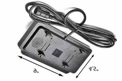
15 Installing the Monitor 33ft Extension Cable Monitor Video Out -3 Amp Fuse Multiplexer Optional Camera Available 1. DC12V-24V (red) 2. Ground (black) 3. Port #3 (blue) 4. Port #2 (white) 5. Port #1 (yellow) Camera Reverse With Confidence 15


16 Monitor Operation UP MENU DOWN V1/V2 ON/OFF Brightness, Contrast, Saturation, Sharpness: Adjust image properties Picture Adjust: Stretch image horizontally (right/left and left/right) Turn: Toggle between mirror/normal image on each individual channel Name: Change name of teach individual channel Trigger Delay: Adjust time delay on each trigger Trigger Source: Toggle channel destination for each trigger Distance Grid: Toggle which channel distance grid lines will display on Grid Position: Adjust position of distance grid lines Auto Power: On: Monitor will automatically turn on when powered. Off: Monitor will only turn on when triggered. Auto: Monitor will follow previous state. Reset: Reset settings to factory default 16 REAR VIEW SAFETY
17 Splicing Red - Power (+) 2. Yellow - Video 3. Green - Mirror / Normal Imaging 4. White - Audio 5. Black - Ground (-) Reverse With Confidence 17

18 Positioning 18 REAR VIEW SAFETY

19 Multiplexer Port #1 Port #2 Port #3 or DVD Backup Reverse With Confidence 19
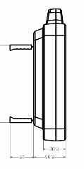
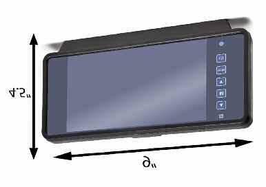
20 Monitor Dimensions 20 REAR VIEW SAFETY
21 Monitor Specifications TFT LCD Digital Monitor Screen Size Digital 7 Dot Resolution 800H x 3 (RGB) x 480V Display Format 16:9 Display Brightness 400cd/m 2 Viewing Angle 90 min Video Input 3 channel Video Source 1Vp-p, 75Ω Power Supply DC 12V-24V (+/-10%) Power Consumption 5W Operating Temperature -10 C C Video System Auto NTSC/PAL Overall Dimensions 9.5 L x 4.5 H x 1 D Weight 400G Impact Rating 5G Dot Pitch 0.192H x V Sync System Internal Reverse With Confidence 21
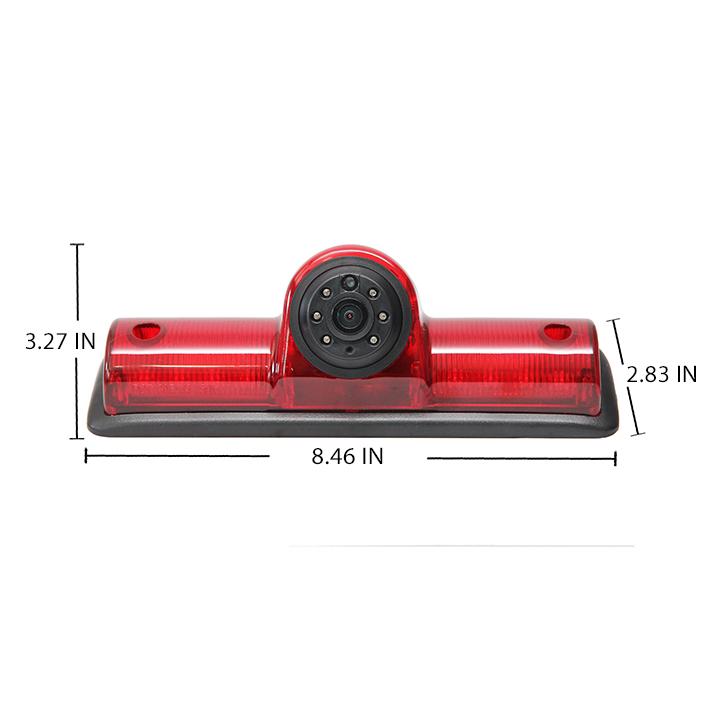


22 Camera Dimensions 22 REAR VIEW SAFETY
23 Camera Specifications Sensor MT9V139 Picture Elements 307,200 pixels Gamma Correction Image Sensor r=0.45 to TV lines PAL:720H x 576V / NTSC:720H x 480V Lens 2.1mm View Angle 130 Sync System Internal Synchronization Night Vision Yes Usable Illumination 0.3 Lux Power Source DC 12V-24V (+/-10%) S/N Ratio More than 48dB Electronic Iris 1/50, 160-1/100,000sec Video Output 1Vp.p 75ohm IR Switch Control CDS Automatic Control Impact Rating 10G Operating Temperature -30 C ~ +50 C / RH 95 % Max Storage Temperature -30 C ~ +60 C / RH 95 % Max Reverse With Confidence 23
24 Troubleshooting Monitor Displays Blue Screen & Displays No Signal Do a hard reset, unplug all cables and power cables from multiplexer (silver box) leave out for 1 minute and then re-connect them. Check to ensure that the connection to the camera is tight. Verify camera cable is plugged into port labeled Backup Camera Verify that the blue positive trigger on power harness is put to power 12v+. If the problem still persists, verify that alternate ports work. If alternate ports do not work, remove Blue Trigger wire from 12V+ and select alternate channels. Monitor Will Not Power-Up (no backlight on power button) Check fuse Check 12v+ to monitor Check ground connection Verify camera is on correct camera input Verify cable is connected to monitor Verify camera is connected to cable Verify chosen camera has audio Verify volume setting No Image On Screen Audio on Camera Connect known working camera and cable to monitor. Verify Blue trigger is receiving power Confirm that the Blue audio trigger is connected to 12v+ 24 REAR VIEW SAFETY
25 Warranty One Year Warranty RVS Systems Inc. warrants this product against material defects for a period of one year from date of purchase. We reserve the right to repair or replace any such defective unit at our sole discretion. RVS Systems Inc. is not responsible for a defect in the system as a result of misuse, improper installation, damage or mis-handling of the electronic components. RVS Systems Inc. is not responsible for consequential damages of any kind. This warranty is void if: defects in materials or workmanship or damages result from repairs or alterations which have been made or attempted by others or the unauthorized use of nonconforming parts; the damage is due to normalware and tear, this damage is due to abuse, improper maintenance, neglect or accident: or the damage is do to use of the RVS Systems Inc. system after partial failure or use with improper accessories. Warranty Performance DURING THE ABOVE WARRANTY PERIOD, SHOULD YOUR RVS Systems PROD- UCT EXHIBIT A DEFECT IN MATERIAL OR WORKMANSHIP, SUCH DEFECT WILL BE REPAIRED WHEN THE COMPLETE RVS Systems INC. PRODUCT IS RE- TURNED, POSTAGE PREPAID AND INSURED, TO RVS Systems INC. OTHER THAN THE POSTAGE AND INSURANCE REQUIREMENT, NO CHARGE WILL BE MADE FOR REPAIRS COVERED BY THIS WARRANTY. Warranty Disclaimers NO WARRANTY, ORAL OR WRITTEN, EXPRESSED OR IMPLIED, OTHER THE ABOVE WARRANTY IS MADE WITH REGARD TO THIS RVS Systems INC. RVS Systems INC. DISCLAIMS ANY IMPLIED WARRANTY OR MERCHANT-ABILITY OR FITNESS FOR A PARTICULAR USE OR PURPOSE AND ALL OTHER WARRANTIES IN NO EVENT SHALL RVS Systems INC. LIABLE FOR ANY INCIDENTAL, SPECIAL, CONSEQUENTIAL, OR PUNITIVE DAMAGES OR FOR ANY COSTS, ATTORNEY FEES, EXPENSES, LOSSES OR DELAYS ALLEGED TO BE AS A CONSEQUENCE OF ANY DAMAGE TO, FAILURE OF, OR DEFECT IN ANY PRODUCT INCLUDING, BUT NOT LIMITED TO, ANY CLAIMS FOR LOSS OF PROFITS Reverse With Confidence 25
26 Disclaimer RVS Systems and/or its affiliates does not guarantee or promise that the user of our systems will not be in/part of an accident or otherwise not collide with an object and/or person. Our systems are not a substitute for careful and cautious driving or for the consistent adherence to all applicable traffic laws and motor vehicle safety regulations. The RVS Systems products are not a substitute for rearview mirrors or for any other motor vehicle equipment mandated by law. Our camera systems have a limited field of vision and do not provide a comprehensive view of the rear or side area of the vehicle. Always make sure to look around your vehicle and use your mirrors to confirm rearward clearance and that your vehicle can maneuver safely. RVS Systems and/or its affiliates shall have no responsibility or liability for damage and/or injury resulting from accidents occurring with vehicles having some of RVS Systems products installed and RVS Systems and/or its affiliates, the manufacturer, distributor and seller shall not be liable for any injury, loss or damage, incidental or consequential, arising out of the use or intended use of the product. In no event shall RVS Systems and/or its affiliates have any liability for any losses (whether direct or indirect, in contract, tort or otherwise) incurred in connection with the systems, including but not limited to damaged property, personal injury and/or loss of life. Neither shall RVS Systems and/or its affiliates have any responsibility for any decision, action or inaction taken by any person in reliance on RVS Systems systems, or for any delays, inaccuracies and/or errors in connection with our systems functions. 26 REAR VIEW SAFETY
27 Take Notes Reverse With Confidence 27

28 If you have any questions about this product, contact: Rear View Safety, Inc Atlantic Avenue Brooklyn, NY BETTER CAMERAS. BETTER SERVICE. IT S OUR GUARANTEE.
Introduction REAR VIEW SAFETY
 TM 1 What s in the Box? 1 Color Weather Proof Backup Camera 7" Color TFT LCD Digital Clip-on Mirror Monitor 1 3 Channel Multiplexer Control Unit 1 66 Extension Cable for Camera 1 Remote Control 1 Power
Backup camera svstem for Nissan NV vans L..JSAFETY A Safe Fleet Brand
 Backup camera svstem for Nissan NV vans Product Manual/ Installation Instructions Rear View Camera Systems Model# RVS-912619 r7 REARVIEW L..JSAFETY A Safe Fleet Brand What s in the Box? COLOR WEATHERPROOF
Please read all of the installation instructions carefully before installing the product. Improper installation will void manufacturer s warranty.
 TM 1 What s in the Box? 1 Color Weather Proof Backup Camera 7" Color TFT LCD Digital Replacement Mirror Monitor 1-3 Channel Multiplexer Control Unit 1-33 Extension Cable for Camera 1 Remote Control 1 Power
What s in the Box? REAR VIEW SAFETY
 TM 1 What s in the Box? 1 Full HD Color Infra-red Weather Proof Camera 1 Full HD 7" TFT LCD Color Monitor w/monitor Mount 1 Power Harness 1 66 Camera Cable 1 Power Connection Wire 1 Screw Kit for installation
Table of Contents
 What s in the Box? 2 Color CCD side cameras w/infra-red weather proof cameras 1 Color CCD w/infra-red weather proof camera 1 DIGITAL 7" LED color monitor with universal mount/ stand and wire 1-66' Camera
Digital Wireless Split screen camera svstem with Cigarette lighter Adaptor
 Digital Wireless Split screen camera svstem with Cigarette lighter Adaptor Digital Wireless Split screen camera svstem with Cigarette lighter Adaptor Product Manual / Installation Instructions Product
Introduction RVS SYSTEMS
 TM 1 What s in the Box? 1 Quad View Digital Wireless Monitor with Cigarette Lighter Adaptor 1 CCD Wireless Backup Camera with Power Cable 1 Extendable Suction Cup Mount for Monitor Table of Contents Introduction...4
Please read all of the installation instructions carefully before installing the product. Improper installation will void manufacturer s warranty.
 TM 1 What s in the Box? 2 Color CCD Weather Proof Side Cameras w/infra-red 2 Color CCD Weather Proof Backup Cameras w/infra-red 1 DIGITAL 7" TFT LCD Quad View Color Monitor with universal mount/stand and
Introduction RVS SYSTEMS
 TM 1 What s in the Box? 1 Quad View Digital Wireless Monitor with Power Harness and Triggers 1 Universal Monitor Mount with Adhesive Bottom 1 CCD Wireless Backup Camera with Power Cable 1 Screw Kit for
What s in the Box? Weatherproof Camera transmitter with Antenna Power Cable 3m Sticker. 2 RVS SyStemS
 1 What s in the Box? Weatherproof Camera transmitter with Antenna Power Cable 3m Sticker 2 RVS SyStemS table of Contents Introduction...4 Features...5 Specifications...6 Installation...7 Operations...8-13
Instruction Manual. G-SERIES Backup Camera System with Built-In Dash Camera RVS BB
 Instruction Manual G-SERIES Backup Camera System with Built-In Dash Camera RVS-776718-BB NOTE! Please read all of the installation instructions carefully before installing the product. Improper installation
Safe-T-Scope Mirror Monitor Backup Camera System
 Safe-T-Scope Mirror Monitor Backup Camera System INSTALLATION/USER MANUAL STSK6630 STSK5530 STSK1030 (Not Shown) 90-21 144th Place Jamaica, NY 11435 1.800.227.2095 www.roscovision.com WARNING 1. To prevent
Model: CAM430MV Wired Multi-View Camera with License Plate / Rear Surface Mount Installation Manual Features
 Model: CAM430MV Wired Multi-View Camera with License Plate / Rear Surface Mount Installation Manual Features Fully Adjustable, Multiple Viewing Angle Smart Camera. High Resolution, 1/2 CMOS Color Camera
Be sure to always check the camera is properly functioning, is properly positioned and securely mounted.
 Please read all of the installation instructions carefully before installing the product. Improper installation will void manufacturer s warranty. The installation instructions do not apply to all types
INVIEW TRUESIGHT CAMERA & MONITOR SYSTEMS MODEL: BCA SERIES
 Document Number: XE-BCA1PM-R0A BCA100-200 Rev180205 TM INVIEW TRUESIGHT CAMERA & MONITOR SYSTEMS MODEL: BCA100-200 SERIES FIRE RESEARCH CORPORATION www.fireresearch.com 26 Southern Blvd., Nesconset, NY
Universal Clip On 4.3 Rear View Mirror Monitor & Camera Pack with Grid-lines
 Universal Clip On 4.3 Rear View Mirror Monitor & Camera Pack with Grid-lines MCPK-43BG User Manual Thank you for purchasing Parkmate s MCPK-43BG 4.3 Rear View Mirror Monitor & Camera Pack with Grid-lines.
B&W RearView Camera Installation & Operation
 B&W RearView Camera Installation & Operation CA52 (Camera) FOR MORE INFORMATION WWW.STRATEGICVISTA.COM BEFORE OPERATING THIS SYSTEM, PLEASE READ THIS MANUAL THOROUGHLY AND RETAIN IT FOR FUTURE REFERENCE
INSTALLATION INSTRUCTIONS:
 INSTALLATION INSTRUCTIONS: Part # SV-5600 PC-F Full Frame Type (Black or Chrome) Part # SV-5500 PC-B Top Bar Type (Black or Chrome) Part # SV- PK Kits with PlateCam and 3.5 LCD monitor FEATURES: Revolutionary
PLCMTR Commercial Grade Camera System
 Please read instructions carefully before installation and use. Installation should be performed by a professional installer. To ensure your safety, the driver should not watch videos or operate features
Owner s/installation Manual
 Owner s/installation Manual 7 Color LCD Monitor Model: M130C For Technical Assistance, please call (800) 638-3600, or for more accessories or replacement parts visit www.magnadynestore.com. Table of Contents
DAY AND NIGHT COLOR CAMERA
 INSTRUCTION MANUAL DAY AND NIGHT COLOR CAMERA MODEL HDC518 Copyright 2007 Clover Electronics U.S.A. All Rights Reserved. PRECAUTIONS To avoid electrical shock, do not open the case of this product. Operate
9.2 TFT LCD COLOR MONITORING SYSTEM With 2 Indoor/Outdoor Color Cameras
 INSTRUCTION MANUAL 9.2 TFT LCD COLOR MONITORING SYSTEM With 2 Indoor/Outdoor Color Cameras MODEL: LCD0935 Copyright 2009 Wisecomm. All Rights Reserved. 1. IMPORTANT SAFETY PRECAUTIONS To prevent fire or
poly-planar Marine Audio System
 ME-52 Expansion Amplifier 1 ME-52 Expansion Amplifier Introduction: The ME-52 is a 2 channel audio amplifier capable of delivering up to 25W RMS per channel. It s compact, water resistant design allows
Wireless 4.5 LCD Display System
 Wireless 4.5 LCD Display System Model: ACA450 Installation/User Manual Features: 4.5" TFT Color LCD Display On Screen Display Function 2.4 GHz Wireless Receiver Automatically Displays Image when Vehicle
B/W PAN/TILT FIXED DOME CAMERA
 B/W PAN/TILT FIXED DOME CAMERA OWNER S MANUAL INSTALLATION AND OPERATION MODEL: BEFORE INSTALLING OR OPERATING THE SYSTEM, PLEASE READ THIS MANUAL. CA1022 Important Safety Instructions Remove all packaging
Model: ACA400 & ACA500 Reverse Camera Installation Manual
 Model: ACA400 & ACA500 Reverse Camera Installation Manual ACA400 ACA500 FEATURES: High Resolution: 1/4 CMOS Color Camera Compact Zinc Alloy Die Cast Body Waterproof Housing 150 Degree Wide View Angle Minimum
WiFi Backup Camera Go Vue
 WiFi Backup Camera Go Vue Product Manual I Installation Instructions Model # RVS-020770 Rear View Safety, Inc. "' 2017 r-, REAR VIEW TM 1 L_JSAF TY A Safe Fleet Brand what s in the Box? 1 Color CCD infra-red
Be sure to always check the camera is properly functioning, is properly positioned and securely mounted.
 Please read all of the installation instructions carefully before installing the product. Improper installation will void manufacturer s warranty. The installation instructions do not apply to all types
Rear View Camera System
 Product Maual IstalIatio Istructios Rear View Camera System RVS-7707101 2009-2010 Rear View Safety Ic. IMPORTANT NOTICE Please read this with maual before proceedig istallatio. Cogratulatios o your purchase
VMA633 OWNER S MANUAL INSTALLATION GUIDE 6.5 WIDE ACTIVE MARTIX TFT COLOUR LCD MONITOR VMA INCH WIDE LCD MONITOR
 6.5 INCH WIDE LCD MONITOR 6.5 WIDE ACTIVE MARTIX TFT COLOUR LCD MONITOR OWNER S MANUAL INSTALLATION GUIDE OWNER S MANUAL WARNING! THE CLARION LCD MONITOR IS DESIGNED FOR NAVIGATION PURPOSE AND REAR SEAT
5.6 Color Rear View Safety System Installation & Operation. RV56 (Includes MO56 monitor & CA56 camera)
") 5.6 Color Rear View Safety System Installation & Operation RV56 (Includes MO56 monitor & CA56 camera) FOR MORE INFORMATION WWW.STRATEGICVISTA.COM BEFORE OPERATING THIS SYSTEM, PLEASE READ THIS MANUAL THOROUGHLY
5.6 Color Rear View Safety System Installation & Operation RV56 (Includes MO56 monitor & CA56 camera) FOR MORE INFORMATION WWW.STRATEGICVISTA.COM BEFORE OPERATING THIS SYSTEM, PLEASE READ THIS MANUAL THOROUGHLY
VEHICLE DVR DASH CAM KIT. HD Video Recording System with Rearview Mirror Monitor, 7.4 -inch LCD Display, Compact Dash Cam, Rear-View Backup Camera
 VEHICLE DVR DASH CAM KIT HD Video Recording System with Rearview Mirror Monitor, 7.4 -inch LCD Display, Compact Dash Cam, Rear-View Backup Camera DESCRIPTION Vehicle DVR Dash Cam Kit HD Video Recording
DCS200/DCS200-09/DCS DCS300/DCS300-09/DCS355
 THE SEEKER 200 SERIES & THE SEEKER 300 SERIES VIDEO INSPECTION SYSTEMS DCS200 (shown) DCS300 (shown) DCS200/DCS200-09/DCS200-05 DCS300/DCS300-09/DCS355 USER S MANUAL Please read this manual carefully and
poly-planar Marine Audio Systems
 ME60BT Bluetooth Amplifier 1 Introduction: The ME60BT is a four channel, 120 Watts RMS Bluetooth wireless audio amplifier, capable of delivering up to 30W RMS per channel. It has a compact, water resistant
PCM-7140 Pulsed Current Source Operation Manual
 PCM-7140 Pulsed Current Source Operation Manual Directed Energy, Inc. 1609 Oakridge Dr., Suite 100, Fort Collins, CO 80525 (970) 493-1901 sales@ixyscolorado.com www.ixyscolorado.com Manual Document 7650-0031
5 B&W Rear View System Camera
 5 B&W Rear View System Camera Instruction Manual MODEL: CA453 www.lorexcctv.com Copyright 2007 LOREX Technology Inc. Thank you for purchasing the Lorex 5 Black & White Rear View System Camera. This system
3.5 TFT LCD CCTV Service Viewer with Wristband LCD35SV
 User Manual 3.5 TFT LCD CCTV Service Viewer with Wristband LCD35SV LCD35SV is a type of product that summarizes views of first-line safety engineers and it is developed specially for technical personnel
LINE VOLTAGE TESTER CT101 USER S MANUAL. Please read this manual carefully and thoroughly before using this product.
 LINE VOLTAGE TESTER USER S MANUAL CT101 Please read this manual carefully and thoroughly before using this product. KEY FEATURES Visual indication of AC or DC voltage Easy to use approved Safe for CAT
GSMR30 OWNER S MANUAL
 GSMR30 OWNER S MANUAL Version 1.0 MP4/MP3/Photo Playback Gauge Series Marine Radio FEATURES 4 Channel Full Range, Class A/B 45W x 4 @ 4Ω IPX5 Water proof INPUTS AND OUTPUTS Bluetooth Audio Streaming Easy
SUPER 7" 4+1 REAR VIEW CAMERA AND MULTIMEDIA KIT
 Automotive components since 1963 SUPER 7" 4+1 REAR VIEW CAMERA AND MULTIMEDIA KIT GB USER MANUAL 1 2 CONTENT: Features... 4 Installation of monitor... 4 Signal cable description... 4 Control cable description...
Weatherproof IR Color Day/Night Cameras
 Weatherproof IR Color Day/Night Cameras Products: CFC6042IR, CFC6042IR2, CFC6042IR3, CFC6043IR, CFC6043IR2, CFC6043IR3 Please read this manual before installing and using this camera and always follow
GMNAV1 Advent Integrated Navigation
 GMNAV1 Advent Integrated Navigation This interface is designed to integrate Navigation into select Buick and Chevrolet Systems. INSTALLATION MANUAL What s in the Box The following items are supplied with
PO Box 409 Hanover, MD TEL (410)
") ME-50 Expansion Amplifier 1 ME-50 Expansion Amplifier Introduction: The ME-50 is a 2 channel audio amplifier capable of delivering up to 25W RMS per channel. It s compact, waterproof design allows for
ME-50 Expansion Amplifier 1 ME-50 Expansion Amplifier Introduction: The ME-50 is a 2 channel audio amplifier capable of delivering up to 25W RMS per channel. It s compact, waterproof design allows for
Camera Features. Package Contents. Camera Features
 Camera Features Camera Features Patented Mirroring Technology Makes Camera Invisible to the Human Eye Yet Allows The Camera to Properly View Security Mirror Form Factor is Ideal for Commercial/Retail Applications
Instruction Manual. Balanced Audio Upgrade Installation. iport IW-21/IW-22 Upgrade Kits. Balanced Audio Upgrade Kit. (iport IW-21)
") Introduction The iport IW Balanced Audio, Balanced Video, and RS-232 Upgrade Kits add functionality and capability to iport IW-21 and IW-22 models. Balanced Audio Upgrade Kit For use with iport IW-21 models.
Introduction The iport IW Balanced Audio, Balanced Video, and RS-232 Upgrade Kits add functionality and capability to iport IW-21 and IW-22 models. Balanced Audio Upgrade Kit For use with iport IW-21 models.
User's Guide Video Borescope Model BR200
 User's Guide Video Borescope Model BR200 Introduction Congratulations on your purchase of this Extech BR200 Video Borescope. This instrument was designed for use as a remote inspection device. It can be
SP-C1 Mobile Docking Station Installation Guide
 SP-C1 Mobile Docking Station Installation Guide Box Contents After you unpack your SP-C1 Mobile Docking Station, make sure everything here is included: 1 x Docking Cradle 1 x Audio Cable 1 x Adhesive Mount
User s Manual Model# TE0408
 Model# Mark Point Corp. / Trailer Eyes User s Manual Model# Runs on battery power 5 minute installation No tools required Portable Affordable Easy Installation Monitor your horses,pets,livestock or valuable
Owner s Manual. TSD-DCPDV DC Power Distribution with Fixed & Variable Outputs. TSD-DCPDV DC Power Distribution. AtlasSound.com
 Owner s Manual with Fixed & Variable Outputs 1 AtlasSound.com Owner s Manual Description The Atlas Sound Variable Block is designed to reduce cost and wiring clutter in installations where multiple DC
Model: LCDM40A 4.0 LCD Rear Vision Mirror Monitor User Manual Features
 Model: LCDM40A 4.0 LCD Rear Vision Mirror Monitor User Manual Features Mirror with built in 4.0 LCD Superbright Monitor Low Profile, Slim Design High Resolution LED Backlit LCD TFT Built in Speaker Two
ple420p 4KHz 6KHz 15KH power in-dash 4 band parametric equalizer
 power 4KHz 6KHz 15KH owner s manual in-dash 4 band parametric equalizer www.pyleaudio.com congratulations... for choosing Pyle Audio, and congratulations on joining a select group of dedicated enthusiasts
User's Guide. Video Borescope. Model BR100
 User's Guide Video Borescope Model BR100 Introduction Congratulations on your purchase of this Extech BR100 Video Borescope. This instrument was designed for use as an inspection device. It can be used
User Guide. Control Box. RoscoLED TM.
 RoscoLED TM Control Box User Guide This guide applies to the following RoscoLED Control Box models: RoscoLED Control Box 300W/Static White (293 22250 0000) RoscoLED Control Box 400W/VariWhite (293 22260
Owner s Manual. TSD-ZDC Audio Impedance Combiner/Divider. TSD-ZDC Audio Impedance Combiner/Divider
 Owner s Manual 1 Owner s Manual Description The Atlas Sound is a universal impedance divider/combiner for passively summing or splitting of mic or line level signals. Features include four balanced 10K
MTX-A Temperature Gauge User Manual
 MTX-A Temperature Gauge User Manual 1. Installation... 2 1.1 Gauge Mounting... 2 1.2 Temperature Sensor Mounting... 2 1.2.1 Changing the MTX-A s Gauge Bezel... 2 1.3 Main Gauge Wiring... 3 1.3.1 Single
User's Guide. MiniTec TM Series Model MN25 MultiMeter
 User's Guide MiniTec TM Series Model MN25 MultiMeter Warranty EXTECH INSTRUMENTS CORPORATION warrants this instrument to be free of defects in parts and workmanship for one year from date of shipment (a
PIM-Mini Pulsed Current Source Operation Manual
 PIM-Mini Pulsed Current Source Operation Manual Directed Energy, Inc. 1609 Oakridge Dr., Suite 100, Fort Collins, CO 80525 (970) 493-1901 sales@ixyscolorado.com www.ixyscolorado.com Manual Document 7650-0007
INSPECTION TOOL. Inspection Video Camera with Color LCD Monitor. EU Environmental Protection. Model: 8802LE,8803LE. Model: 8802LE,8803LE
 INSPECTION TOOL Inspection Video Camera with Color LCD Monitor Model: 8802LE,8803LE EU Environmental Protection Waste electrical products should not be disposed of with household waste. Please recycle
PRODUCT USER MANUAL 12V. 5 Mirror + REVERSE camera IP67 PAGE 1 GX53HDM ABC-123. Mount INSTRUCTION MANUAL. Guide Lines
 PRODUCT USER MANUAL 5 Mirror + REVERSE camera 5 12V 120 IP67 ABC-123 Screen Size Clip-On Mount Voltage Wired Wide Angle PAGE 1 Parking IP67 Rating Number Plate Guide Lines Mount INTRODUCTION WELCOME Thank
CONTENTS PRODUCT FEATURES... EG-2 SAFETY PRECAUTIONS... EG-2 PARTS DESCRIPTION... EG-3 INSTALLATION AND ADJUSTMENT... EG-4 SPECIFICATIONS...
 Thank you for your purchase of this product. Before operating the product, please read this instruction manual carefully to ensure proper use of the product. Please store this instruction manual in a safe
User's Guide. Phase Sequence and Motor Rotation Tester Model
 User's Guide Phase Sequence and Motor Rotation Tester Model 480403 Introduction Congratulations on your purchase of the Extech Model 408403 Motor and Phase Rotation Indicator. This handheld instrument
Dual Mount Universal Kit Aftermarket CMOS Camera with Optional Parking Gridlines Installation Instructions (Kit # )
") Please read thoroughly before starting installation and check that kit contents are complete. Items Included in Kit: Chassis Harness Power Harness with RCA connectors Camera mounted on license plate bracket
Please read thoroughly before starting installation and check that kit contents are complete. Items Included in Kit: Chassis Harness Power Harness with RCA connectors Camera mounted on license plate bracket
Motion LED Floodlight Covert Color Camera
 ESFL-X650 Operational Manual Motion LED Floodlight Covert Color Camera Camera FEATURES 1/3 Sony ExView HAD CCD II 650 TV Lines (Color) / 700TV Lines (B&W) 3.6mm Board Lens 0.01 Lux @ F2.0; 0 Lux @ IR on
INSTRUCTION MANUAL. * Design and Specifications are subject to change without notice. ver. 1.0 PRINTED IN KOREA
 INSTRUCTION MANUAL * Design and Specifications are subject to change without notice. ver. 1.0 PRINTED IN KOREA INSTRUCTION MANUAL Thank you for purchasing this product. For proper usage and application,
TSD-SEQ6 Sequencer Controller
 Owner s Manual 1 AtlasSound.com Owner s Manual Description The Atlas Sound features 6 outputs that are configurable individually to be either a 24VDC output or Hard Switch Contact Closure (CC). There are
INSTALLATION MANUAL. ST-BTWD650IR2812 B or W Weatherproof Day/Night Infrared Color Camera
 INSTALLATION MANUAL ST-BTWD650IR2812 B or W Weatherproof Day/Night Infrared Color Camera PACKAGE CONTENTS This package contains: One ST-BTWD650IR2812 camera with Black or White housing One extension tube
TSD-DA28 2x8 Balanced Line Distribution Amplifier
 2x8 Balanced Line Distribution Amplifier 1 Description The Atlas Sound 2x8 distribution amplifier is designed to provide clean, isolated signal distribution locally or to remote locations. The unit allows
IR Varifocal IP66 Weatherproof Cameras
 IR Varifocal IP66 Weatherproof Cameras Products: CFC6067VF, CFC6067VF2 Please read this manual before using your camera, and always follow the instructions for safety and proper use. Save this manual for
ZN55 User Manual. LGX ZN55 Industrial IP67 LED Touchscreen Display. User Manual. Version 1.1 PN: ZN55-08
 LGX ZN55 Industrial IP67 LED Touchscreen Display User Manual Version 1.1 PN: ZN55-08 1 Table of Contents Important Safety Instructions...3 1. Features... 3 2. Specifications... 4 3. Installation... 5 3.1
Sapling Converter Box
 Installation Manual Sapling Converter Box SCB-100-000-1 Version Number 1.2 Current as of March 15, 2015 The Sapling Company, Inc. (+1) 215.322.6063 P. (+1) 215.322.8498 F. 2-Wire Converter Box (SCB-100-000-1)
Indoor Dome Camera DWC-D6351D DWC-D6351DB
 Indoor Dome Camera DWC-D6351D DWC-D6351DB ABOUT MANUAL Before installing and using the camera, please read this manual carefully. Be sure to keep it handy for future reference. 10252013 PRECAUTIONS Do
QuickTouch (QT4) Owner s Manual
 Owner s Manual") QuickTouch (QT4) Owner s Manual 4-Function Hand-Held Wireless Remote Control IMPORTANT SAFETY INSTRUCTIONS READ AND FOLLOW ALL INSTRUCTIONS SAVE THESE INSTRUCTIONS Table of Contents SECTION I. APPLICATION...
QuickTouch (QT4) Owner s Manual 4-Function Hand-Held Wireless Remote Control IMPORTANT SAFETY INSTRUCTIONS READ AND FOLLOW ALL INSTRUCTIONS SAVE THESE INSTRUCTIONS Table of Contents SECTION I. APPLICATION...
PROFESSIONAL SECURITY MADE EASY. Security Camera. Day/Night INSTRUCTION MANUAL V1.1
 PROFESSIONAL SECURITY MADE EASY Security Camera Day/Night EN V. INSTRUCTION MANUAL Introduction Congratulations on your purchase of This CCTV camera from ZOSI.This camera can operate in almost all lighting
INTELLIGENT DOCKING STATION USERS MANUAL
 Kodiak Mobile by Jotto Desk 209 W. Easy St., Rogers, AR USA 72756 Customer Service: 877.455.6886 http://www.kodiakmobile.com PART NUMBER: 450-4011 - Last Update: 06.2009 INTELLIGENT DOCKING STATION USERS
NOTICE OF INTENDED INSTALLATION AND USE
 * JBL Audio equipped vehicles will require additional part # DP-TYJBL1 audio interface. NOTICE OF INTENDED INSTALLATION AND USE THE ROSEN MULTI-MEDIA NAVIGATION SYSTEMS CONTAIN AN INTERNAL VIDEO PLAYER,
Secured Series: Hub Plus Kit Single Door Controller Package Installation Manual
 Secured Series: Hub Plus Kit Single Door Controller Package Installation Manual This package is designed to simplify the connections to our Secured Series Hub Plus Controller. This will translate into
Adjustable Timing Control PN 8680
 Adjustable Timing Control PN 8680 IMPORTANT: Read the instructions before attempting installation. Parts Included: 1 - Timing Control, PN 8680 1 - Control Knob 1-3/8" Bushing 1-2-Pin Weathertight Connector
TOUCHBOX. iphone I N S T R U C T I O N M A N U A L
 TOUCHBOX W I R E L E S S C O N T R O L L E R iphone I N S T R U C T I O N M A N U A L Thank you for purchasing TouchBox by ZAETECH. Disclaimer TouchBox is for show and off road use only. It may not be
MOBILE SAFETY DVR1543K. CLIP ON REARVIEW MIRROR KIT with 4.3-INCH LCD MONITOR FRONT & REAR CAR CAMCORDER with DUAL MOUNTING REVERSING CAMERA
 MOBILE SAFETY DVR1543K REARVIEW MIRROR CAR DRIVING RECORDER KIT CLIP ON REARVIEW MIRROR KIT with 4.3-INCH LCD MONITOR FRONT & REAR CAR CAMCORDER with DUAL MOUNTING REVERSING CAMERA 3.0 MEGA PIXEL CAMERA
AC4G-D User s Manual
 AC4G-D User s Manual Entire contents of this manual 2004 Active Cool Ltd. Ashkelon, Israel. Reproduction in whole or in part without permission is prohibited. Active Cool and AC4G-D are registered of Active
GSMR20 OWNER S MANUAL
 GSMR20 OWNER S MANUAL Version 1.0 FEATURES AM/FM/Radio/Preset 180 Watts Max Power Pre-Amplifier Outputs Splash Proof LCD Display Bluetooth Audio Streaming (Bluetooth 3.0) A2DP Audio Streaming USB/AUX Input
Precautions. Please read carefully before using this product.
 Thank you for purchasing this BEWITH Mirror Media MM-1. It is designed to give you many years of enjoyment. Please read all instructions in this manual before attempting operation and keep it handy for
CM-Z2212GY. Outdoor IR Speed Dome PTZ Camera
 Outdoor IR Speed Dome PTZ Camera User s Guide CM-Z2212GY 1201-1205, Sangda Mansion, High Technology Park, SAFETY PRECAUTIONS WARNING 1. Be sure to use only the standard adapter that is specified in the
CONTENTS PRODUCT FEATURES... EG-2 SAFETY PRECAUTIONS... EG-2 PARTS DESCRIPTION... EG-3 INSTALLATION AND ADJUSTMENT... EG-4 SPECIFICATIONS...
 Thank you for your purchase of this product. Before operating the product, please read this instruction manual carefully to ensure proper use of the product. Please store this instruction manual in a safe
VPC-64/ VPX-64 VIDEO POLE CAMERA OPERATION MANUAL
 VPC-64/ VPX-64 VIDEO POLE CAMERA OPERATION MANUAL RESEARCH ELECTRONICS INTERNATIONAL 455 Security Drive Algood, TN 38506 U.S.A. +1 931-537-6032 http://www.reiusa.net/ COPYRIGHT RESEARCH ELECTRONICS INTERNATIONAL
PRODUCT USER MANUAL. Rear view Monitor Reversing Camera IP67 G427. Adhesive Mount Guides1. Screen Size. IP67 Rating Mount
 PRODUCT USER ANUAL Rear view onitor Reversing Camera 120 4.3 Screen Size + ABC-123 Wired Adhesive ount Parking Guides1 PAGE Wide Angle IP67 IP67 Rating Number Plate ount INSTRUCTION ANUAL INTRODUCTION
THECHARGEHUB.COM. User Manual. For Square & Round Models
 THECHARGEHUB.COM User Manual For Square & Round Models User Manual THECHARGEHUB.COM 7-Port USB Universal Charging Station Table of Contents General Safety Information...2 Care and Maintenance...3 Introduction...4
Speaker Selectors Models SSW-L4 EX and SSW-L6 EX. User Manual. SSW-L4 EX (bottom) and SSW-L6 EX (top)
 and SSW-L6 EX (top)") Speaker Selectors Models SSW-L4 EX and SSW-L6 EX User Manual SSW-L4 EX (bottom) and SSW-L6 EX (top) Table of Contents Important Safety Precautions...2 What s Included...2 Introduction... 3 Front Panel...
Speaker Selectors Models SSW-L4 EX and SSW-L6 EX User Manual SSW-L4 EX (bottom) and SSW-L6 EX (top) Table of Contents Important Safety Precautions...2 What s Included...2 Introduction... 3 Front Panel...
Installation and Operation Guide for PD5200 and PD5300 Automatic Transfer Switch
 Installation and Operation Guide for PD5200 and PD5300 Automatic Transfer Switch PD52 PD52S & PD52DCS PD53-100 te: The PD52S & PD52DCS are provided with LED lights. The GREEN LIGHTS indicate Shore Power
ipad Charge & Sync Cart Model MCC2 ipad Cart 430-MCC2-User Manual-010 Is a Registered Trademark of Apple Inc. ipad
 ipad Charge & Sync Cart Model MCC2 ipad Cart ipad Is a Registered Trademark of Apple Inc. 430-MCC2-User Manual-010 1. ipad Cart Specifications MCC2 Mobile Charge & Sync Cart Extra Drawer Reserved space
Outdoor IR Camera. DVR / Camera Communication System Series
 348Z Outdoor IR Camera DVR / Camera Communication System Series Please read instructions thoroughly before operation and retain it for future reference. For the actual display & operation, please refer
Kramer Electronics, Ltd. USER MANUAL. Model: WP-210E. XGA Line Driver
 Kramer Electronics, Ltd. USER MANUAL Model: WP-210E XGA Line Driver Contents Contents 1 Introduction 1 2 Getting Started 1 3 Overview 1 4 Your WP-210E XGA Line Driver 2 4.1 Your WP-210E: Available in 3
Follow these simple installation instructions to get professional results.
 Follow these simple installation instructions to get professional results. LED Real -Time Display Wireless Remote Control System. Dash Mount Charger / Cradle for Wireless Remote. 4 Normal Modes - 3 Million
SD1306. Speed Dome IP Camera. Quick User Guide
 SD1306 Speed Dome IP Camera Quick User Guide Table of Contents I. Camera Introduction... 1 1. Package Contents... 1 2. Hardware Installation... 2 2.1 Factory Default... 6 3. SD card Compatibility List...
HD-SDI Vandal Dome Camera
 HD-SDI Vandal Dome Camera DWC-HF21M4TIR ABOUT MANUAL Before installing and using the camera, please read this manual carefully. Be sure to keep it handy for future reference. 12112013 PRECAUTIONS Do not
Owner s Manual. TSD-DCPDV DC Power Distribution with Fixed & Variable Outputs. TSD-DCPDV DC Power Distribution. AtlasIED.com
 Owner s Manual with Fixed & Variable Outputs 1 AtlasIED.com Owner s Manual Description The AtlasIED Variable Block is designed to reduce cost and wiring clutter in installations where multiple DC power
TDM-150 TIMER DISPLAY
 TDM-150 TIMER DISPLAY TECHNICAL MANUAL Covers TDM-150D, TDM-150F Version 1.1 August 2016 Safety Precautions Caution Read Instructions: Read and understand all safety and operating instructions before using
Wireless 5G HDMI Transmitter, Receiver & 4 Port Switch With 1080p and 3D compatible
 Wireless 5G HDMI Transmitter, Receiver & 4 Port Switch With 1080p and 3D compatible MODEL #: W-HDM3D5G-20M-KIT 2012 Avenview Inc. All rights reserved. The contents of this document are provided in connection
Installation & Operation Instructions
 Installation & Operation Instructions Deluxe Spot & Flood Light 405620-3 To avoid the risk of accidents or damage to this product, it is essential to read these instructions thoroughly before this product
INSTRUCTION MANUAL. Model True RMS AC/DC 30A Mini Clamp-on Meter. Introduction. True RMS AC Current and Voltage
 INSTRUCTION MANUAL Model 380942 True RMS AC/DC 30A Mini Clamp-on Meter True RMS AC Current and Voltage Measure low current with high resolution to 0.1mA AC and 1mA DC Auto Power Off One touch DCA zero