EasyCon GSM. Installation manual
|
|
|
- Marilyn Corey Walsh
- 5 years ago
- Views:
Transcription


1 Installation manual
2 Contents Description of device functions... page 3. Description of the terminal block... page 3. Installation instructions... page 3. LED signals... page 3. Reset (factory default)... page 4. Control with caller ID function... page 4. Output settings... page 4. Input settings... page 5. Power monitor... page 5. Tamper... page 6. Life signal... page 6. SMS forward... page 6. Description of voice calls... page 6. Description of SMS... page 7. Calendar of events... page 7. Expansion module... page 7. Signal strength monitoring... page 7. SMS programming... page 7. Monitoring station... page 9. Software updates... page 9. Connected battery... page 10. Other commands... page 10. Circuit diagram... page 10. Frequently asked questions and answers... page 10. CE certificate... page 11. page 2.
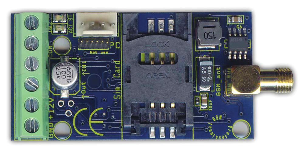
3 Description and functions of the device the GSM communicator may be used as a complement to alarm control systems as a 2 input GSM transmitter. capable of sending voice or SMS messages to 8 phone numbers. Voice messages with a length of up to 8 seconds can be sent concerning the 2 inputs and power failure. An extra identification message may be recorded (up to 16 seconds), which is played before the alarm message. the open collector (OC) output of the device may be used for control with caller ID. capable of forwarding SMS messages received by the SIM card to a preset phone number. monitors power failure and GSM signal strength; GSM signal strength can be read out and drawn up as a one-hour resolution graph with the programming software. possesses a event list, which records signals, GSM status, incoming calls and phone numbers. PC programming is possible with ProRead software and optional programming cable! Description of the terminal block I2, C, I1 Input2 and Input1 controlled by short-circuit or cut in relation to COM port O Output of the module: OC=open collector +, - Power supply: += 9-18 VDC; -= GND Installation instructions Check signal strength with your mobile. It is possible that signal strength is not sufficient at the desired place. If so, modify device location before installation. Locate device far from electromagnetic interferences, such as electric motors, or transformer of the alarm system. Do not install device in wet or high humid places. Connection of the antenna: You may connect the antenna to a SMA plug. In case of poor signal strength use a higher gain antenna. Disable PIN requirement, voice mail, and call notification on your SIM card. Occasionally a newly bought SIM card needs to be activated (usually by making an outgoing call). Caller ID function needs to be activated on your SIM card by the Mobile Service Provider (with some models it is not activated by default). Insert SIM card. Connect antenna to device. Connect as indicated. Device is ready to be connected to power supply. Make sure that the power supply is sufficient for the operation of the device. The module s resting current is 20mA, but may reach 300mA during communication. After connecting to the power supply, the red LED goes on, which indicates that the device is trying to contact the GSM tower (up to 1 min). When the red LED light goes off and the green LED is flashing, the module is ready for operation and has connected to the network. The number of flashes indicates signal strength. For programming the power supply needs to be connected. LED signals LED status = green ACT LED = red Number of flashes: Number of LED flashes between the breaks. Only green LED flashes No error, GSM module connected, the number of LED flashes shows signal strength. 1..2=poor signal strength, 3=sufficient, 4..5=excellent Green LED on GSM module s connection rejected. Red LED on Shows initialization on start-up, otherwise an event message is being sent (SMS, voice call). page 3.


4 Green and red flashes at the same time Error code by the number of flashes: 1 flash: GSM module initialisation 2 flashes: GSM module defective 3 flashes: SIM card not inserted 4 flashes: SIM card blocked by PIN code 10 flashes: Modem mode Control with caller ID function You need to have your Service Provider enable the caller ID function in the SIM card of your GSM module. The caller ID function needs to be enabled in each telephone from which you would like to control the device. The GSM module accepts phone numbers stored on the SIM card, therefore depending on the SIM card 250 or 500 numbers can be set. You may add phone numbers to the SIM card by inserting it to a regular mobile phone, or you may view/edit the SIM card s address book in the Caller ID tab. First you need to upload it with the Read button, then after editing write it in with the Send button. The address book can be imported/exported in EXCEL csv format with the Open/Save button. The caller ID function can be switched off in the GSM module (Output tab / Control with Caller ID), in this case the device accepts every phone number. The caller ID function can be used for output control (Output tab / Control with Incoming Call). The module provides feedback about status with the number of ringtones: - Output control in bistable mode: few ringtones (0-1) = control, many ringtones (3-4) = end of control Output settings Output modes can be set in the Output tab. MONOstable mode: output is controlled for the preset time, then releases ( seconds). BIstable (two-state) mode: changes state on every command and stays in that state indefinitely. page 4.
![Input settings Inputs can be used in different operation modes [In (e.g.:1;2)tab/types of Input]: 24h normal: continuously monitors input, in case of alarm sends signals. On (e.g.:1;2) tab/inverted Operation: in normal position input expects short-circuit, if function is checked in normal position it expects cut.](/docs-images/92/109159264/images/5-0.jpg "SMS/Voice call about restore: if checked, notification is received about input restore also. In case of SMS (Other/Restore) message is sent.")

5 Input settings Inputs can be used in different operation modes [In (e.g.:1;2)tab/types of Input]: 24h normal: continuously monitors input, in case of alarm sends signals. On (e.g.:1;2) tab/inverted Operation: in normal position input expects short-circuit, if function is checked in normal position it expects cut. SMS/Voice call about restore: if checked, notification is received about input restore also. In case of SMS (Other/Restore) message is sent. Siren sound: In case of VOICE call, emits a siren sound (20-30 seconds). Sending a voice message: In case of VOICE call, it plays recorded voice. Attention! If neither siren sound, nor voice message is checked, GSM automatically disconnects line, and there is no sound! Siren sound and voice message can be used together, in this case siren sounds shortly then voice message is played. Power monitor The device constantly monitors incoming voltage (12V, GND terminal block), if voltage goes below 10V (external battery low) it is capable of sending alarm. Notification about restore can be requested. page 5.
 and time of message can be set. Only full hours of the clock can be set: e.g. 12:00, 13:00, etc.")

6 Life signal Settings can be made on Life Signal tab: it is recommended to request a test message every week or every second week to check proper operation of device. Frequency (every days) and time of message can be set. Only full hours of the clock can be set: e.g. 12:00, 13:00, etc. You can also set how many days after setting you wish to receive the first message. Life signal can only be requested as SMS, with a custom message. SMS forward Other tab/sms Forward: with this function the module forwards every uninterpretable message to a preset phone number. This is a useful function to receive the pre-paid SIM card balance message. Description of voice calls Every outgoing VOICE call needs to be confirmed by user. Answering the phone qualifies as confirmation, no code or pressing of button is required. You do not need to listen to the siren sound/voice message, answering the phone means confirmation. Avoiding voic confirmation, your ringtone time needs to be set shorter than your voic pickup. This way the module disconnects the phone line before voic confirmation (Other tab/ringtone Time). By default, if anyone answers the call, the alarm is confirmed and no further numbers are called. If circular calling function is turned on, everyone has to confirm the call. With the number of redials you can set how many outgoing calls the module can make in one alarm period. Unless for a good reason do not set a value less than 50. An 8 second message can be recorded for the following signals: inputs, power failure alarm. You may record an identification message of less than 16 seconds. For practical reasons you may want to include the place of installation and name of facility in the message. This message is played before the voice message. Its use is not compulsory. Order of voice messages: Siren sound + identification message + Alarm message page 6.

7 Description of SMS For each input you may set a different SMS message and the phone numbers you wish to send them to. The SMS text message can not be more than 32 characters long; use of special characters is not recommended. Calendar of events The module is capable of storing events, which can be read out with the programming software. If you would like to use this function, set the clock of the GSM module, because events will be time stamped accordingly. Possible events: signals (input, power monitor), GSM status (GSM connected/disconnected), incoming calls with phone numbers. The device stores signal strength and GSM status (connected/disconnected/roaming) for each event. You may prepare an access identification and/or working hour management system by using the calling phone numbers. Signal strength monitoring The module constantly monitors signal strength, and saves the lowest signal strength data every hour. Signal strength data can be read out using the programme, where it is displayed as a graph. When performing maintenance you can check for constant signal strength. The module is capable of storing signal strength data for the last 20 years. SMS programming The basic functions of the device can be programmed via SMS. The SMS text message needs to start with the security code followed by the SMS command and parameter. One message can only contain one command. The default security code is 1234 (the actual command is in bald type). SMS command Description Parameter 1234codXXXX Security code change XXXX = new security code, alphanumeric 1234swtel1,tel2,..tel8 Change or delete phone numbers to be notified Tel1 = telephone number 1 Tel8 = telephone number 8 Tel = d, delete number 1234opar1,par2,tttt,kk Installation settings Par1,2(input)=ssssssssvvvvvvvv S= send SMS can be 1 or 0 V = send VOICE message These are the messages that belong to the phone numbers. 1234k1 Activate output Control output k1on In case of bistable output Switches on bistable output 1234k1of In case of bistable output Switches off bistable output 1234clkhhmm Clock settings hhmm=hours minutes e.g o clock 9 minutes 1234t Status enquiry Device sends notification about its actual status. page 7.
8 Programming installation settings: ssssssss = The eight s letters determine whether you wish to send SMS to the phone numbers to be notified. If s =1 the device sends SMS; if 0 it does not. If you leave it blank, previous settings remain. vvvvvvvv = The eight v letters determine whether you wish to send VOICE message to the phone numbers to be notified. If s =1 the device makes a voice call; if 0 it does not. If you leave it blank, previous settings remain. tttt = types of the two inputs. t can be a value between 0 and 5, a letter i (= inverted) or n (= non-inverted) needs to be put before the value. E.g.: i1 = normal inverted input 0 Input off 1 24 hour normal input 2 Not used If you put an i before the number, the input will be inverted. kk = type of output. k = a value between 1 and 7. (K) MONO/BI stable Alarm control Caller ID control 1 BI stable OFF OFF 2 MONO ON OFF 3 BI ON OFF 4 MONO OFF ON 5 BI OFF ON 6 MONO ON ON 7 BI ON ON E.g.: Input1 sends SMS to 2nd and 3rd phone number, Input2 sends voice message to 1st phone number, input1 is 24 hour normal, input2 is inverted normal. The output is monostable, controlled with alarm. 1234o , ,,,,n1i1n0n0,22 page 8.

 then sends SMS, and finally makes VOICE calls.")
9 Monitoring station The module is capable of sending its signals in Contact ID format to a monitoring station through VOICE channel. Codes and zones might be edited in the Monitoring Station tab. Here you can enter the customer code and 2 monitoring station phone numbers. Monitoring station alerts can be used in parallel with other alarms (SMS, VOICE), so the device can notify both remote surveillance and customer. The module first tries to call monitoring station (max. 8 redials) then sends SMS, and finally makes VOICE calls. You may check the status of sending in Functions menu/module Status in Error Codes/CID; in case of error you may also learn the reason for error. You can change your TX/RX levels; however, after modification module needs to be restarted. When notifying monitoring station the use of high gain antenna is recommended, since perfect transmission requires sufficient signal strength (above 60%). Monitoring station signals: Input1, Input2, Power supply, Periodic life signal. Changeable customer code and changeable zone. Software updates You can easily update the module s software and this way be notified of new functions and error corrections. It is always the programming software that contains the firmware, so make sure to download the latest version. Start Functions/Software Update menu, then check the firmware version at the bottom. You may change your current version for an older one; however, it is not recommended. If there is a newer version, press the programme update button, and the programme updates the module in two steps (it takes about 3 minutes). In case of successful update the window closes automatically. If there is no such menu, or the service is unavailable, update in service shops (old modules). You may view the module s software version in menu Functions/GSM Software Version. page 9.

10 Other commands In the Functions/Monitor menu you may monitor and save GSM traffic. In case of defective operation, you should monitor error and send it in to our technical assistant who will of service. In the Functions/Module Status menu you may check module status. Input/output states and module error code are shown in real time. The status of Contact ID sending is shown in error code. The Description/Circuit Diagram menu shows the circuit diagram of the module in use, helping installation. In Basic Data menu you may enter data concerning the installation, these can be saved in File Operations/Save, because these data are not stored in the module. Saving data for later use is recommended. The function does not save caller ID phone numbers and recorded voices, only configuration settings. The process of PC programming: after powering up the module, connect the programming cable if the name of the device shows click start in the telephone tab enter the phone numbers you wish to notify, then fill in the other tabs finally, transfer the configuration and save the settings by clicking the send button if you wish to use the caller ID function, enter the telephone numbers in the caller identification tab if you do not wish to use the factory default siren sound, upload your pre-recorded messages in the voices tab finally, it is recommended to save the configuration in File Operations, filling in the basic data. Circuit diagram Frequently asked questions and answers Caller identification does not work: Check with the service provider whether caller ID function is enabled in your module s SIM card. Check the caller ID function in the controller telephone. In the module s settings control with incoming call needs to be checked. Check if the phone numbers are stored on the SIM card. ACT LED remains red after alarm: Module cannot send message either because SIM card has run out of credit or incorrect phone number has been entered. Check the SMS centre number of the module s SIM card. page 10.
11 EasyCon GSM CE certificate page 11.
ProLine GSM. Installation manual
 Installation manual ContentS Description of device functions... page 3. Line simulkator function... page 3. Description of the terminal block... page 4. Installation instructions... page 4. LED signals...
ProCon GSM INSTALLATION AND APPLICATION MANUAL. ProCon GSM manual. .gsm-komunikatorji.com. for module version 1.4
 informacije in naročila: info@gsm-komunikatorji.com.gsm-komunikatorji.com ProCon GSM INSTALLATION AND APPLICATION MANUAL for module version 1.4 1 Index I. Basic descriptions... 3 II. Steps of installation...
WiLARM-ContactID GSM Module Installation Guide Version: 2.0
 Content Main functions and operation of the GSM module... 3 Parts of the module.. 3 Mini USB connector. 4 Terminal contacts.... 4 Power supply. 4 Input.. 4 Prefix numbers... 4 LEDs... 5 LED operation chart
UP100-GSM. GSM based intercom and access control. Installation and user manual
 UP100-GSM GSM based intercom and access control Installation and user manual UP100-GSM REV.1.4 20/01/2014 Table of contents 1 Functions...3 2 Features...3 3 Application area...3 4 Operation...3 4.1 Visitor
GPRS Pager 3 INSTALATION AND USER MANUAL
 GPRS Pager 3 INSTALATION AND USER MANUAL 1 Table of contents 1 Main functions of the GPRS Pager3...3 2 Operating mode, installation...3 2.1 Installation if no local network is available...3 2.2 Instalation
WiLARM-ONE GSM Module Installer Manual Version: 2.0
 Content WiLARM-ONE.. 1 The parts of the module. 3 Mini USB connector 3 Terminal contacts... 3 Power supply. 3 Inputs and outputs. 3 Power monitoring input. 3 Temperature sensor input.... 3 Relay and NC/NO
Conversion of Contact ID event codes sent by alarm control panel via GSM and PSTN channel to SMS messages
 GSM ProCom Description GSM and PSTN communication Management of 2 independent SIM cards Reception of incoming calls, possibility for restriction Installable behind PBX Management of different prefix numbers
MobilSwitch-5c. 1. Operation of the GSM device: Multi channel GSM signaling and remote control unit with analog, digital, counter inputs
 MobilSwitch-5c Multi channel GSM signaling and remote control unit with analog, digital, counter inputs The MobilSwitch-5c GSM device is developed for industrial signaling and remote controlling purposes.
MobilSwitch - Micro. 1. Operation: General purpouses GSM remote signal and remote control modules with 2 inputs and 2 relay outputs
 MobilSwitch - Micro General purpouses GSM remote signal and remote control modules with 2 inputs and 2 relay outputs The MobilSwitch-Micro module is a general, industrial-grade GSM module, developed for
ecoline GSM Adapter INSTALLATION AND APPLICATION MANUAL for module version v2.0 and higher Document version:
 ecoline GSM Adapter INSTALLATION AND APPLICATION MANUAL for module version v2.0 and higher Document version: 1.31 22.11.2013 Table of contents 1 Application area... 3 2 Functions... 3 3 Settings... 3 4
Mobil Switch-Nano. 1. Operation: Industrial grade GSM signalling and remote control module with common input and relay output
 Mobil Switch-Nano Industrial grade GSM signalling and remote control module with common input and relay output The MobilSwitch-Nano module is a general, industrial-grade GSM module, developed for remote
ProCon GSM PROFESSIONAL GSM/GPRS TRANSMITTER
 PROFESSIONAL GSM/GPRS TRANSMITTER INSTALLATIONAL AND USER S GUIDE Version: 2.1 Table of contents Device description and function... 3 Figure 1: Device operation... 3 Module buildup... 4 Figure 2: the buildup
MobilTherm 2ad. 1. How the interface works: GSM temperature alarm module with auxiliay inputs and relay outputs
 MobilTherm 2ad GSM temperature alarm module with auxiliay inputs and relay outputs The MobilTherm-2ad is a GSM temperature and remote signaling module, designed for GSM based remote control, remote signal.
Instalation manual to GSM dialer with mobile phone FVK 41 EZS
 Instalation manual to GSM dialer with mobile phone FVK 41 EZS 1 Contents: 1. Basic information...3 1.1 Description of device...3 1.2 Posibilities of use...3 1.3 Specifications...3 1.4 Package content...3
TECHNICAL MANUAL NEW PANDINO 4. GSM Telephonics Communicator WITH QUAD-BAND GSM INDUSTRIAL MODULE
 TECHNICAL MANUAL NEW PANDINO 4 GSM Telephonics Communicator WITH QUAD-BAND GSM INDUSTRIAL MODULE GSM TELEPHONE COMMUNICATOR IS IN CONFORMITY WITH ALL THE ESSENTIAL REQUIREMENT OF DIRECTIVE 1999/5/CE 89/336/CEE
GSM communicator GD-06 Allegro Complete manual
 GSM communicator GD-06 Allegro Complete manual The GD-06 ALLEGRO is a universal GSM dialer and controller. It can be used for both home and industrial automation purposes, for security applications or
GPRS-T1. Monitoring Converter. SATEL sp. z o.o. ul. Schuberta Gdańsk POLAND tel
 Monitoring Converter GPRS-T1 Program version 1.01 gprs-t1_en 04/09 SATEL sp. z o.o. ul. Schuberta 79 80-172 Gdańsk POLAND tel. + 48 58 320 94 00 info@satel.pl www.satel.pl WARNINGS The module should only
GSM WIRELESS TELELINK
 Packs Infotel Ltd GSM WIRELESS TELELINK INSTALLER S MANUAL Notes To Cancel the GSM dialler Press the # Key while the GSM is speaking to you. 2 Index 1. FEATURES 2. 3. PURPOSE AND APPLICATION 4. CONNECTION
GSM Easy INSTALLATION AND USER S GUIDE MINIATURE GSM/GPRS COMMUNICATOR. Version: 2.1
 GSM Easy MINIATURE GSM/GPRS COMMUNICATOR INSTALLATION AND USER S GUIDE Version: 2.1 Index Device description and function... 3 Figure 1: Device operation... Module buildup... 4 Figure 2: The buildup of
AV-4000 GSM AV-4000 DVR
 E a s y L o a d e r AV-4000 GSM AV-4000 DVR (for LED keypads) Integrated Alarm Control panel & Communicator Series 4000 Appendix for GSM Alarm Panels Version 1.05 Edition I This product is subject to continuous
Installation Manual. GSM-3V/AB & ABK V3.5 (1200 keypad) Wiring. Important Notes: SIM card. Installation
 Wiring. Important Notes: SIM card. Installation") -V/AB & ABK V.5 (2 ) Important Notes: ) Before you install this equipment, please read this full manual. Installation Manual Wiring 8) Carefully follow the wiring instructions. 2) Before fully installing
-V/AB & ABK V.5 (2 ) Important Notes: ) Before you install this equipment, please read this full manual. Installation Manual Wiring 8) Carefully follow the wiring instructions. 2) Before fully installing
Comsec Protection Systems
 Comsec Protection Systems - - - - Comsec Protection Systems - - Comsec Protection Systems UP200-GSM-RD Intercom and access control unit operating on mobile GSM network INTRODUCTION The UP200-GSM-RD is
GC-10 Wireless Control Box. User Guide
 Wireless Control Box User Guide 1. Introduction This Installation and User Guide will assist you in installing and configuring the Brodersen SMS Alarm Unit. The guide covers the installation of the configuration
Ethernet communication module ETHM-1 Plus
 Ethernet communication module ETHM-1 Plus Firmware version 2.05 ethm1_plus_en 07/18 SATEL sp. z o.o. ul. Budowlanych 66 80-298 Gdańsk POLAND tel. + 48 58 320 94 00 www.satel.eu IMPORTANT The module should
GPRS ADAPTER INSTALLATION AND USER MANUAL. for module version v2.24 and higher
 GPRS ADAPTER INSTALLATION AND USER MANUAL for module version v2.24 and higher Table of contents 1 Main function of the Adapter...3 2 System operation...3 2.1 Transmission through GPRS...4 2.1.1 Router
GPRS/SMS Reporting Module GPRS-T2
 GPRS/SMS Reporting Module GPRS-T2 Program version 2.01 gprs-t2_en 11/11 SATEL sp. z o.o. ul. Schuberta 79 80-172 Gdańsk POLAND tel. + 48 58 320 94 00 info@satel.pl www.satel.eu WARNINGS The module should
4 Channel GSM Controller Installer Manual
 ! WARNING! Only fully Qualified Personnel should install or service this Device. 4 Channel GSM Controller Installer Manual 4 Channel Controller 2T-Technology www.2t-tec.com SN: 01001 Device Telephone Number:
GPRS-T4. GPRS/SMS Reporting Module. SATEL sp. z o.o. ul. Schuberta Gdańsk POLAND tel
 GPRS/SMS Reporting Module GPRS-T4 Program version 3.01 gprs-t4_en 10/13 SATEL sp. z o.o. ul. Schuberta 79 80-172 Gdańsk POLAND tel. + 48 58 320 94 00 info@satel.pl www.satel.eu WARNINGS The module should
INT-GSM. GPRS communication module. Firmware version 1.00 int-gsm_en 07/18
 INT-GSM GPRS communication module Firmware version 1.00 int-gsm_en 07/18 SATEL sp. z o.o. ul. Budowlanych 66 80-298 Gdańsk POLAND tel. +48 58 320 94 00 www.satel.eu IMPORTANT The module should be installed
Mobile 2 Heating (M2H) Installer Manual
 Installer Manual") ! WARNING! Only fully Qualified Personnel should Install or service this Device. Mobile 2 Heating (M2H) Installer Manual Alarm - 2 - Mobile 2T-Technology www.2t-tec.com SN: 01001 Device Telephone Number:
! WARNING! Only fully Qualified Personnel should Install or service this Device. Mobile 2 Heating (M2H) Installer Manual Alarm - 2 - Mobile 2T-Technology www.2t-tec.com SN: 01001 Device Telephone Number:
GSM module G10T (v.2.3x) Installation manual. TRIKDIS, JSC Draugystės st. 17, LT Kaunas Lithuania
 Installation manual. TRIKDIS, JSC Draugystės st. 17, LT Kaunas Lithuania") GSM module G10T (v.2.3x) Installation manual TRIKDIS, JSC Draugystės st. 17, LT-51229 Kaunas Lithuania E-mail: info@trikdis.lt www.trikdis.lt Table of Contents GSM module G10T... 3 Operating... 3 Outside
GSM module G10T (v.2.3x) Installation manual TRIKDIS, JSC Draugystės st. 17, LT-51229 Kaunas Lithuania E-mail: info@trikdis.lt www.trikdis.lt Table of Contents GSM module G10T... 3 Operating... 3 Outside
The Packs Infotel. GSM Converter V2. Installation Manual V7
 The Packs Infotel GSM Converter V2 Installation Manual V7 1 Index Connecting the M60 to the GSM Converter 3 1. GSM Converter description 4 2. Equipment installation 4 3. Led functions. 5 4. GSM Converter
SMS Commander Manual
 SMS Commander Manual For the GB0101S V1.2 Before Attempting to connect or operate this product, please read these instructions in its entirety, especially the guarantee conditions. TABLE OF CONTENTS Introduction...3
GSM PAGER VT 21. Installation manual. VARIANT plus, spol. s.r.o., U Oburky 5, TREBIC,
 Pager VT 21 manual II GSM PAGER VT 21 Installation manual VARIANT plus, spol. s.r.o., U Oburky 5, 674 01 TREBIC, www.variant.cz technik@variant.cz Date of create 16. 5. 2007 VARIANT plus s.r.o. VARIANT
UP200-GSM Intercom and access control unit operating on mobile GSM network
 UP200-GSM Intercom and access control unit operating on mobile GSM network INTRODUCTION The UP200-GSM is an intercom unit which as a cell phone can call the owner s mobile or landline phone. By pressing
Fixed Wireless Phone. User Manual
 Fixed Wireless Phone User Manual V1.0 Content 1. Introduction... 1 2. Important Information... 2 3. Dos & Don ts... 2 4. Views... 4 5 Key board Introduction... 4 6. Installation... 5 6.1 SIM card installation...
ETHM-2. Ethernet Module. SATEL sp. z o.o. ul. Schuberta Gdańsk POLAND tel
 Ethernet Module ETHM-2 Firmware version 1.0 ethm2_en 09/08 SATEL sp. z o.o. ul. Schuberta 79 80-172 Gdańsk POLAND tel. + 48 58 320 94 00 info@satel.pl www.satel.pl SATEL's goal is to continually improve
MANUAL PELITT MINI 1
 MANUAL PELITT MINI 1 TABLE OF CONTENTS 1. Warnings 3 2. Getting Started 3 3. Your Phone 4 4. File Manager 4 5. Phone book 4 6. Fun&Games 4 7. Call center 4 8. Messaging 4 9. Multimedia 5 10. Organizer
Anonymous Call Rejection
 Contents Anonymous Call Rejection 4 Call Block 5 Call Forward 6-7 Call Return 8 Call Waiting 9 Caller ID 10-11 Do Not Disturb 12 Find Me 13 Selective Call Forwarding 14 Speed Dial 15 Three-Way Calling
JVA SMS Gateway User Manual
 www.jva-fence.com.au JVA SMS Gateway User Manual PTE0319 JVA SMS Gateway User Manual Introduction The PTE0319 JVA SMS Gateway enables a group of JVA Z Series energisers to be controlled and monitored by
GSM POWER OUTAGE ALARM SYSTEM (Single Phase) Model: GSM-0308POA1P
 Model: GSM-0308POA1P") GSM POWER OUTAGE ALARM SYSTEM (Single Phase) Model: GSM-0308POA1P Table of Contents Application.... 3 Instructions. 4 Installation Diagram....5 Device Design... 5 Technical Parameter....6 Setup Instruction.6
GSM POWER OUTAGE ALARM SYSTEM (Single Phase) Model: GSM-0308POA1P Table of Contents Application.... 3 Instructions. 4 Installation Diagram....5 Device Design... 5 Technical Parameter....6 Setup Instruction.6
FSK TX CELLULAR PLUS. Installation and Programming Guide. Tel:
 FSK TX CELLULAR PLUS Installation and Programming Guide Tel: 0861 105 962 www.fsk.co.za INTRODUCTION The FSK TX Cellular Plus (TXC+) is a highly featured GSM based unit which is used for the transmission
MSS-UP200-GSM Single Dwelling GSM Intercom Unit. Operation Manual. [Ver /5/2015]
![MSS-UP200-GSM Single Dwelling GSM Intercom Unit. Operation Manual. [Ver /5/2015]](/thumbs/92/107778619.jpg "MSS-UP200-GSM Single Dwelling GSM Intercom Unit. Operation Manual. [Ver /5/2015]") [Ver. 1.0 2/5/2015] INTRODUCTION The MSS-UP200-GSM is a GSM intercom unit which can phone the owner s mobile or landline phone. By pressing the call button on the intercom, it makes the voice connection
[Ver. 1.0 2/5/2015] INTRODUCTION The MSS-UP200-GSM is a GSM intercom unit which can phone the owner s mobile or landline phone. By pressing the call button on the intercom, it makes the voice connection
SOLO NX EXT COMPACT GSM DOOR ENTRY UNIT WITH 1, 2 or 4 CALL BUTTONS
 SOLO NX EXT COMPACT GSM DOOR ENTRY UNIT WITH 1, 2 or 4 CALL BUTTONS Contents 1 FOR YOUR SAFETY... 3 2 INTRODUCTION... 4 3 SOLO-NX FEATURES AND APPLICATIONS... 5 4 START UP... 6 5 LED INDICATION... 7 6
General. Bluetooth. Troubleshooting. 1. How do I re-connect my BlueSonic? 2. Why won t my BlueSonic go into pairing mode? 3. Is my BlueSonic charged?
 Bluesonic FAQ General 1. What is the main difference between the BlueSonic and other Bluetooth devices?... 2. What is included in the BlueSonic package? 3. How does the BlueSonic use the Bluetooth technology?
: DOOR ENTRY UNIT USER MANUAL EIS-LCD. Programming Software
 : DOOR ENTRY UNIT EIS-LCD Programming Software v.2.0 2018 Page 1 Contents 1 FOR YOUR SAFETY...5 2 INTRODUCTION...6 3 EIS-LCD, EIS-40 FEATURES AND APPLICATIONS...7 4 START UP...8 5 LED INDICATION...9 6
RADIO PAGING - REMOTE CONTROL SYSTEM
 & RADIO PAGING - REMOTE CONTROL SYSTEM Contents CONTENTS... 2 GENERAL CHARACTERISTICS... 3 TECHNICAL DATA... 4 INSTALLATION... 5 PROGRAMMING OF "IRIDA"... 5 A. FACTORY SETTINGS... 5 B. SUPERVISOR PHONE
GC 055. GSM Remote Monitoring. Operating and installation instructions
 GSM Remote Monitoring Operating and installation instructions GC 055 GSM, GPRS Programmable Communicator Transmits input conditions/controls outputs Measures analogue data Access control system/dallas
Contact Ethernet Converter module Installation and programming reference
 Contact Ethernet Converter module Installation and programming reference Features: Encrypted Ethernet communication 24 hour, two way connection to the Monitoring Station 4 programmable and remotely controlled
: DOOR ENTRY UNIT. Programming Software USER MANUAL
 : DOOR ENTRY UNIT Programming Software MODELS: EIS-1, EIS-2 OR EIS-4 v.02 2018 Contents 1 FOR YOUR SAFETY...4 2 INTRODUCTION...5 3 EIS-1, EIS-2, EIS-4 FEATURES AND APPLICATIONS...6 4 START UP...7 5 LED
Aristel Networks Pty Ltd. All Round Cabling Solutions NEOS3003-3G01. Operating Manual * NEOS G01
 Aristel Networks Pty Ltd All Round Cabling Solutions NEOS3003-3G01 Operating Manual * NEOS 3003-3G01 Supports 3G/UMTS 800/850/900/1900/2100 MHz bands Telstra-Vodafone-Optus supported in all areas. * Model:
MobilGate - 128d. 1. Operation of MobilGate-128d. Gate and barrier control GSM module with 2 inputs and 2 outputs for 128 phone numbers
 MobilGate - 128d Gate and barrier control GSM module with 2 inputs and 2 outputs for 128 phone numbers MobilGate-128d is an industrial GSM module developed for remotely controlling doors, garage doors
GSM Unit PU from software version Connecting cable RJ 12/ RJ 12, enclosed
 Document number A 30594 00 IT 74 1 CMC-TC GSM Unit DK 7320.820 Important note: For reasons of clarity, these user instructions contain only the most significant details and information and similarly cannot
GSM GATE VT 10. version 5.4 and higher. Installation manual. VARIANT plus, spol. s.r.o., U Oburky 5, TREBIC, Issued on May 16, 2007
 Gate VT 10 GSM GATE VT 10 version 5.4 and higher Installation manual VARIANT plus, spol. s.r.o., U Oburky 5, 674 01 TREBIC, technik@variant.cz www.variant.cz Issued on May 16, 2007 VARIANT plus s.r.o.
SOLO KP SOLO KP LCD COMPACT MULTI-APARTMENT GSM DOOR ENTRY UNIT USER MANUAL
 SOLO KP SOLO KP LCD COMPACT MULTI-APARTMENT GSM DOOR ENTRY UNIT Contents 1 FOR YOUR SAFETY... 4 2 INTRODUCTION... 5 3 SOLO-KP AND SOLO-KP LCD FEATURES AND APPLICATIONS... 6 4 START UP... 7 5 LED INDICATION...
User Manual. GSM Fixed Wireless Phone (Model: GSM-938) Introduction
 Introduction") User Manual Introduction The latest style desktop wireless telecommunication products. It can send wireless SMS and voice at anytime, anywhere, suitable remote countries or mountains. Please take care
User Manual Introduction The latest style desktop wireless telecommunication products. It can send wireless SMS and voice at anytime, anywhere, suitable remote countries or mountains. Please take care
GSM AUTO DIALER WITH IR BEAM DETECTOR
 GSM AUTO DIALER WITH IR BEAM DETECTOR Remote Monitoring & Control using your mobile phone. www.gsm-activate.co.uk MODEL NUMBER IRV2 Page 1 Product Information Our GSM Auto-Dialer is a versatile unit which
GSM GENERATOR OUTPUT MONITORING ALARM SYSTEM (Three Phase) Model: GSM-0308G3P
 Model: GSM-0308G3P") GSM GENERATOR OUTPUT MONITORING ALARM SYSTEM (Three Phase) Model: GSM-0308G3P Table of Contents Application.... 3 Instructions. 3 Installation Diagram....4 Device Design... 4 Technical Parameter....5 Setup
GSM GENERATOR OUTPUT MONITORING ALARM SYSTEM (Three Phase) Model: GSM-0308G3P Table of Contents Application.... 3 Instructions. 3 Installation Diagram....4 Device Design... 4 Technical Parameter....5 Setup
Advanced Calling Features
 Click HERE to return to the Home Page. Advanced Calling Features General Information Advanced Calling Services work only on calls made within the Advanced Calling Serving area. These services are not available
USER MANUAL Mobeye Smoke Detector CM2400 Mobeye Heat Detector CM2400H. SW version 3.n
 USER MANUAL Mobeye Smoke Detector CM2400 Mobeye Heat Detector CM2400H SW version 3.n CONTENT 1. General description 1 2. Getting started 2 2.1 Insert a SIM card 2 2.2 Insert the batteries 2 2.3 Enter the
GSM CODELOCK ACCESS CONTROL UNIT
 GSM CODELOCK ACCESS CONTROL UNIT EIS ENTRY-LOCK Programming Software v.1.4.20160816 Contents 1 FOR YOUR SAFETY...3 2 INTRODUCTION...4 3 EIS ENTRY-LOCK FEATURES AND APPLICATIONS...5 4 START UP...6 5 LED
STD Simple Telemetry Application. Owner s Manual
 STD47 1.0 Simple Telemetry Application Owner s Manual Table of Content 1. Safety Information... 4 2. Main Functions:... 5 2.1. Start-Up alarm message... 5 2.2. Digital Output control:... 5 2.3. Digital
Digital Voice Services Residential User Guide
 Digital Voice Services Residential User Guide 2 P a g e * Feature Access Codes *11 Broadworks Anywhere (pulling call to alternate phone) *62 Access Voicemail *72 Call Forwarding Always Activation *73 Call
SS-10 3G USER MANUAL FIXED CELLULAR TERMINAL. DOC. NO: SS-10 3G-14 (Rev. 01) Page 1 of 20
 Page 1 of 20") SS-10 3G FIXED CELLULAR TERMINAL USER MANUAL DOC. NO: SS-10 3G-14 (Rev. 01) Page 1 of 20 Revision History: Revision 01 Original document 12 August 2010 CONTENTS 1 INTRODUCTION...3 2 FEATURES...4 2.1 PHYSICAL
SS-10 3G FIXED CELLULAR TERMINAL USER MANUAL DOC. NO: SS-10 3G-14 (Rev. 01) Page 1 of 20 Revision History: Revision 01 Original document 12 August 2010 CONTENTS 1 INTRODUCTION...3 2 FEATURES...4 2.1 PHYSICAL
ARGUS GSM Module. Installation, Programming and User Manual
 ARGUS GSM Module Installation, Programming and User Manual C GUARANTEE During the guarantee period the manufacturer shall, at its sole discretion, replace or repair any defective product when it is returned
SMS Transceiver V3 User manual
 SMS Transceiver V3 User manual SMS Transceiver V3 - User manual ver. 1.8.3 - Fw: 3.0.7 - Sw: 1.6.2 Contents Page 1. Introduction 3 2. Connections 3 2.1 Inputs 3 2.2 Outputs 3 2.3 Power supply 3 2.4 Contacts
ARGUS GSM Communication Module. Installation, Programming and User Manual
 ARGUS GSM Communication Module Installation, Programming and User Manual C GUARANTEE During the guarantee period the manufacturer shall, at its sole discretion, replace or repair any defective product
The JA-80Y GSM communicator
 CANCEL MENU NAMES CALLS WRITE READ SPACE The communicator is a component of the Jablotron Oasis 80 system. It is designed to be installed within the control panel housing. When connected to a GSM network
A TECHNICAL INFO A. External GSM AT420 DATE :
 DATE :02-02-04 A TECHNICAL INFO A External GSM AT420 The external GSM AT420 is a GSM data modem. It allows a communication with the A when a cabled telephone connection is impossible. This modem can be
Premium Phone with 100% nuisance call blocking and mobile sync Quick Set-up and User Guide
 Premium Phone with 100% nuisance call blocking and mobile sync Quick Set-up and User Guide Digital Cordless Phone with Answer Machine You ll need a Caller Display service from your network provider to
Sentar V80 Watch User Manual
 Sentar V80 Watch User Manual Please read this manual carefully before starting to use the watch, pictures for reference only. 1.Preparation 1.1. Check if the watch is of the correct model and has complete
GPRS-T6. GPRS/SMS Reporting Module with Power Supply
 GPRS/SMS Reporting Module with Power Supply GPRS-T6 Program version 3.01 gprs-t6_en 10/13 SATEL sp. z o.o. ul. Schuberta 79 80-172 Gdańsk POLAND tel. + 48 58 320 94 00 info@satel.pl www.satel.eu WARNINGS
GSM GATE VT 10. version 7.0 and higher. Installation manual. VARIANT plus, spol. s.r.o., U Obůrky 5, TŘEBÍČ. Issued on January 10, 2012
 Gate VT 10 manual GSM GATE VT 10 version 7.0 and higher Installation manual VARIANT plus, spol. s.r.o., U Obůrky 5, 674 01 TŘEBÍČ www.variant.cz technik@variant.cz Issued on January 10, 2012 VARIANT plus
GSM module G10 (v.1.3x) User manual. JSC UAB TRIKDIS Draugystės str. 17, LT Kaunas LITHUANIA Webpage:
 User manual. JSC UAB TRIKDIS Draugystės str. 17, LT Kaunas LITHUANIA Webpage:") GSM module G10 (v.1.3x) User manual JSC UAB TRIKDIS Draugystės str. 17, LT-51229 Kaunas LITHUANIA E-mail: info@trikdis.lt Webpage: www.trikdis.lt Contents GSM module G10... 3 Operation... 3 Outside view...
GSM module G10 (v.1.3x) User manual JSC UAB TRIKDIS Draugystės str. 17, LT-51229 Kaunas LITHUANIA E-mail: info@trikdis.lt Webpage: www.trikdis.lt Contents GSM module G10... 3 Operation... 3 Outside view...
GSM Communicator PSTN SIA DC-05 Protocol to SIA DC-09 Protocol & SMS Alert
 PSTN Alert To Wireless Alert! Compatible With Most Of The PSTN Security Control Panel. Special Designed For Your Existing PSTN Alarms Systems! PSTN SIA DC-05 Protocol to SIA DC-09 Protocol & SMS Alert
ARDUINO BASED GSM/SMS Remote Control Unit USING. SIM800 GSM Module
 ARDUINO BASED GSM/SMS Remote Control Unit USING SIM800 GSM Module Designed by ERIC BROUWER April 2017 Contents Introduction... 4 SIM Card requirements... 5 SIM Card Installation... 5 Electrical Connections...
Keypad LCD (software version 3.10) CA-10 plus
 CA-10 plus") PROGRAMMING AND INSTALLATION MANUAL Keypad LCD (software version 3.10) CA-10 plus GDAŃSK ca10plci_e 09/03 WARNING Due to safety reasons, alarm system should be installed by qualified personnel only. Because
PROGRAMMING AND INSTALLATION MANUAL Keypad LCD (software version 3.10) CA-10 plus GDAŃSK ca10plci_e 09/03 WARNING Due to safety reasons, alarm system should be installed by qualified personnel only. Because
ATL20 ATL30 Automatic transfer switch controller
 I 194 GB 07 07 ATL20 ATL30 Automatic transfer switch controller REMOTE CONTROL SOFTWARE MANUAL Summary Introduction... 2 Minimum resources of the PC... 2 Installation... 2 Activation of the PC-ATL connection...
AT&T Phone For Business User Guide
 AT&T Phone For Business User Guide Table of Contents Welcome Welcome/Contact and Support...3 AT&T Phone for Business Accessing AT&T Phone for Business... 3-6 How to Register...4 Account Overview Voicemail
The device works in conjunction with standard alarm systems and is designed for the transmission of alarm messages by GSM network.
 GsmAlarm-330 The device works in conjunction with standard alarm systems and is designed for the transmission of alarm messages by GSM network. FEATURES Transmission of alarm messages to a central monitoring
Voice Fax. User Manual
 Copyright 2007 UAB Teltonika. All rights reserved. Reproduction, transfer, distribution or storage of part or all of the contents in this document in any form without the prior written permission of UAB
Short user manual. D460 D465. Register your product and get support at
 D460 D465 Short user manual Philips cordless phone Philips cordless phone with answering machine Register your product and get support at www.philips.com/support Important safety instructions Warning The
THANK YOU FOR VOTING TEXECOM INSTALLATION MANUAL. Digi-modems. Issue 3
 THANK YOU FOR VOTING TEXECOM INSTALLATION MANUAL Digi-modems Issue 3 Contents Com300 & Com2400 Installation Manual Contents 1. Regulatory Requirements... 3 General...3 Approval... 3 REN Rating... 3 2.
: DOOR ENTRY UNIT USER MANUAL EIS-R. Programming Software. v
 : DOOR ENTRY UNIT EIS-R Programming Software v.1.4.20161115 Contents 1 FOR YOUR SAFETY...3 2 INTRODUCTION...4 3 EIS-R FEATURES and APPLICATIONS...5 4 START UP...6 5 LED INDICATION...7 6 CONNECTION DIAGRAM...8
USER MANUAL FOR GS100/GS1003G
 USER MANUAL FOR GS100/GS1003G 1 Table of Contents 1. INTRODUCTION... 3 2. FEATURES... 3 3. OPERATION... 3 4.CONNECTION DETAILS... 4 5.CONFIGURATION... 5 5.1 Hyper Terminal Setting... 5 5.2 GS100 Configuration...
WT-1010C2 GSM ALARM SYSTEM
 WT-1010C2 GSM ALARM SYSTEM User Manual WWII TTUU RR AA CC OORR PP OO RR AA TT IIOO NN SS DD NN BB HH DD Contents 1. Getting Started 4 1.1 In the Packaging....4 1.2 Viewing the WT-1010C2..4 2. Introduction
GSM communicator G09 (v.1.61) User Manual and Installation Guide. Draugystes g. 17, LT Kaunas
 User Manual and Installation Guide. Draugystes g. 17, LT Kaunas") GSM communicator G09 (v.1.61) User Manual and Installation Guide Draugystes g. 17, LT-51229 Kaunas E-mail: info@trikdis.lt www.trikdis.lt Purpose of the document This document introduces the features of
GSM communicator G09 (v.1.61) User Manual and Installation Guide Draugystes g. 17, LT-51229 Kaunas E-mail: info@trikdis.lt www.trikdis.lt Purpose of the document This document introduces the features of
SOFTWARE VERSION 3.3. CD P/N Rev. C
 SOFTWARE VERSION 3.3 CD P/N 7301538 Rev. C 2 4 Introduction 1 4 General Specification: 1.1 4 Factory defaults parameters: 1.2 5 Basic Functionality 1.3 5 Password Protection 1.4 6 Operation 1.5 6 SMS support
Emergency Dialer Monitoring Station
 www.skylinkhome.com Emergency Dialer Monitoring Station MODEL: MS-2001 TM P/N. 101A128 DEC, 2000 SKYLINK TECHNOLOGIES INC., 2213 Dunwin Drive, Mississauga, Ontario L5L 1X1 CANADA Tel : (905) 608-9223 (800)
GSM communicator G16 USER MANUAL
 USER MANUAL UAB TRIKDIS Draugystės str. 17, LT-51229 Kaunas LITHUANIA E-mail: info@trikdis.lt Webpage: www.trikdis.lt Contents SAFETY REQUIREMENTS... 2 DESCRIPTION... 3 LIST OF COMPATIBLE CONTROL PANELS...
GSM 2G/3G MULTI SWITCH 240v
 GSM 2G/3G MULTI SWITCH 240v Activate devices with your mobile phone. Call & Text activation, switch and timer mode www.gsm-activate.co.uk MODEL NUMBER SWV3-2G-SWITCH (2G version) SWV3-3G-SWITCH (3G version)
: DOOR ENTRY UNIT USER MANUAL. Programming Software. v
 : DOOR ENTRY UNIT Programming Software MODELS: EIS-1, EIS-2 OR EIS-4 v.1.4.20161115 Contents 1 FOR YOUR SAFETY...3 2 INTRODUCTION...4 3 EIS-1, EIS-2, EIS-4 FEATURES and APPLICATIONS...5 4 START UP...6
Forum 500 Forum 5000 Voic System Forum Voic
 Forum 500 Forum 5000 Voice-Mail System Forum Voicemail User Guide Welcome to Proximus Thank you for choosing a Proximus product that stands for the best in quality matched with high design standards. Forum
IP Centrex Administrator Guide Release 2.0
 IP Centrex Administrator Guide Release 2.0 2012 by Cox Communications. All rights reserved. No part of this document may be reproduced or transmitted in any form or by any means, electronic, mechanical,
Calling Overview Advanced Features Voice Call Video Call Call Logs Speed Dialing
 Overview... -2 Voice Call... - Making Voice Calls... - International Calls... - Answering Voice Calls... -4 Recording the Other Party s Voice... -4 Answering Machine... -4 Playing Messages... -5 Video
Contents USER FEATURES... 2 CAN REMOTE CONTROL BE SECURE?... 2 HOW THE SYSTEM WORKS... 2 REMOTE CONTROL BY PHONE... 3
 Contents USER FEATURES... 2 CAN REMOTE CONTROL BE SECURE?... 2 HOW THE SYSTEM WORKS... 2 REMOTE CONTROL BY PHONE... 3 1. GENERAL RULES FOR REMOTE CONTROL VIA SMS INSTRUCTIONS... 3 2. SETTING (ARMING) BY
RUKRA GSM/PSTN INTERFACE_ENG_V1 ARTICLE NUMBER: RK Read this manual carefully before you start the installation or programming
 RUKRA GSM/PSTN INTERFACE_ENG_V1 ARTICLE NUMBER: RK-1201 Assembled by : Engineer: Installation date : Phone number elevator : PIN : PUK: Battery changed on date : Name : Keep this manual on a save place,
GSM 2G/3G MULTI SWITCH 12v
 GSM 2G/3G MULTI SWITCH 12v Activate devices with your mobile phone. Call & Text activation, switch and timer mode www.gsm-activate.co.uk MODEL NUMBER 3GV4SW-12V Page 1 Product Information Our 2G/3G GSM
Register your product and get support at. D450 D455. Short user manual
 Register your product and get support at www.philips.com/support D450 D455 Short user manual Important safety instructions Warning The Electrical network is classified as hazardous. The only way to power
GSM TEMPERATURE ALARM DIALLER
 GSM TEMPERATURE ALARM DIALLER Remote Monitoring & Control using your mobile phone www.gsm-activate.co.uk Page 1 Product Information Our GSM Temperature Dialer is a versatile unit based on our successful