IPBX 230. Multi-Service IP PBX USER'S MANUAL
|
|
|
- Alison McCormick
- 5 years ago
- Views:
Transcription
1 USER'S MANUAL Multi-Service IP PBX IPBX 230 Headquarters: No. 25, Alley 15, Lane 120, Sec. 1. Nei-Hu Rd, Taipei 114, Taiwan TEL: FAX: Version: 1.1 Date: 2006/11/07 P/N: Beijing Branch: 3F, A Building, 113 Zhi Chun Lu, HaiDian District, Beijing, China Zip Code: TEL: ~87 FAX:
2

3 IPBX 230 User s Manual TAINET IPBX 230 Administration Guidelines Version 1.5 Beta 2 (build 0553) i
4
5 IPBX 230 User s Manual Copyright 2006 TAINET Communication System Corp. All rights reserved Notice This document is protected by the international copyright law. No part of this publication may be reproduced by any means without the expressed permission of Tainet Communication System Corporation. TAINET is a registered trademark, and IPBX 230 is a trademark of Tainet Communication System Corporation. Other product names mentioned in this manual are used for identification purposes only and may be trademarks or trademarks of their respective companies. The information provided from Tainet Communication System Corporation is believed to be accurate. Any changes and enhancements to the product and to the information thereof will be documented and issued as a new release to this manual. Trademark All products and services mentioned herein are the trademarks, service marks, registered trademarks or registered service marks of their respective owners. iii
6 IPBX 230 User s Manual About This Manual This section guides users on how to use the manual effectively. The manual contains information needed to install, configure, and operate TAINET s IPBX 230. The summary of this manual is as follows: Chapter 1: Introduction Presents overview, application, and other general information on the IPBX 230. Chapter 2: System Configuration This chapter describes how to configure system parameters used by TAINET IPBX 230. Chapter 3: Service Configuration This chapter describes details to configure various services built in the TAINET IPBX 230. Chapter 4: IP PBX Configuration This chapter introduces steps to provision the IP telephony part of the IP PBX. Chapter 5: Feature Configuration This chapter introduces a feature is a logical entity presenting a function module of IP PBX. Chapter 6: Example Provisioning This chapter introduces several practical configuration examples of TAINET IPBX 230 deployment. iv
7 IPBX 230 User s Manual Symbols Used in This Manual 3 types of symbols may be used throughout this manual. These symbols are used to advise the users when a special condition arises, such as a safety or operational hazard, or to present extra information to the users. These symbols are explained below: Warning: This symbol and associated text are used when death or injury to the user may result if operating instructions are not followed properly. Caution: This symbol and associated text are used when damages to the equipment or impact to the operation may result if operating instructions are not followed properly. Note: This symbol and associated text are used to provide the users with extra information that may be helpful when following the main instructions in this manual. v
8 IPBX 230 User s Manual LIMITED WARRANTY TAINET s DISTRIBUTOR shall be responsible to its customers for any and all warranties, which it makes relating to Products, and for ensuring that replacements and other adjustments required in connection with the said warranties are satisfactory. TAINET warrants to DISTRIBUTOR that the Products to be delivered hereunder will be free of defects in material and workmanship under normal use and service for a period of twenty-four (24) months [twelve (12) months in Taiwan] following the date of shipment to DISTRIBUTOR. If during the warranty period, any component part of the equipment becomes defective by reason of material or workmanship, and DISTRIBUTOR notifies TAINET of such defect within seven days after knowing of such defect, TAINET shall, for any Product that TAINET agrees is defective, at its option, supply a replacement part, request return of equipment to its plant for repair, or perform necessary repair at the equipment s location. At TAINET's option, DISTRIBUTOR shall destroy any Product that TAINET agrees is defective and shall provide satisfactory proof of such destruction to TAINET. TAINET is not responsible for Products damaged by misuse, neglect, accident or improper installation, or if repairs or modifications were made by persons other than TAINET s own authorized service personnel, unless such repairs by others were made with the written consent of TAINET. THE ABOVE WARRANTY IS IN LIEU OF ALL OTHER WARRANTIES, EXPRESSED OR IMPLIED. THERE ARE NO WARRANTIES THAT EXTEND BEYOND THE FACE HEREOF, INCLUDING, BUT NOT LIMITED TO, WARRANTIES OF MERCHANTABILITY AND FITNESS FOR A PARTICULAR PURPOSE, AND IN NO EVENT SHALL TAINET BE LIABLE FOR CONSEQUENTIAL DAMAGES. If DISTRIBUTOR extends to its customers any additional warranty with respect to Products that is broader in scope than the warranty provided by TAINET, DISTRIBUTOR shall be solely responsible for any and all liabilities, obligations and damages resulting from the extension of such warranty. TAINET shall not be liable to any person for any special or indirect damages, including, but not limited to, lost profits, from any cause whatsoever arising from or in any way connected with the manufacture, sale, handling, repair, maintenance or use of the Products, and in no event shall TAINET s liability exceed the purchase price of the Products. Software Products are provided as is and without warranty of any kind. TAINET disclaims all warranties including the implied warranties of merchantability and fitness for a particular purpose. TAINET shall not be liable for any loss of use, interruption of business or indirect, special, incidental or consequential damages of any kind. TAINET shall do its best to provide vi
9 end users with Software updates during the warranty period under this Agreement. IPBX 230 User s Manual TAINET has not been notified of any intellectual property rights or others which may be infringed by the Products or the promotion, marketing, sale (or resale), or servicing thereof in the Territory, but TAINET makes NO WARRANTY, EXPRESS OR IMPLIED, WITH RESPECT THERETO. vii
10
11 IPBX 230 User s Manual CONTENTS CHAPTER 1. OVERVIEW GENERAL DESCRIPTION INSTALLATION CHAPTER 2. SYSTEM CONFIGURATION PBX SYSTEM TIME SETUP System Time Zone Real Time Clock (RTC) Setup ON-BOARD WAN SETUP Static IP DHCP PPPoE LAN Only ON-BOARD LAN SETUP LAN ROUTING Add a Route Edit a Route Delete a Route DYNAMIC DNS SETUP Enable Dynamic DNS Disable Dynamic DNS QOS SETUP Enable QoS Disable QoS VIRTUAL SERVER Add a Service Edit a Service Delete a Service MAINTENANCE Storage Backup SIP UA CDR Log System Events Active Calls FIRMWARE UPGRADE ix
12 IPBX 230 User s Manual 2.11 REBOOT CHAPTER 3. SERVICE CONFIGURATION NTP SERVICE Enable NTP Service Disable NTP Service STUN SERVICE Enable STUN Service Disable STUN Service TFTP SERVICE Enable TFTP Service Disable TFTP Service DHCP SERVICE Enable DHCP Service Disable DHCP Service IP PBX SERVICE Service & Configuration Advance...43 CHAPTER 4. IP PBX CONFIGURATION USER CONFIGURATION Add a User Edit a User Delete a User USER GROUP CONFIGURATION Add a User Group Edit a User Group Delete a User Group DEVICE CONFIGURATION IP Phone Extension of IP Phone ROUTE CONFIGURATION Add a Route Edit a Route Delete a Route ROUTE GROUP CONFIGURATION Add a Route Group Edit a Route Group Delete a Route Group...60 x
13 IPBX 230 User s Manual 4.6 SIP TRUNK CONFIGURATION Add a SIP Trunk Edit a SIP Trunk Delete a SIP Trunk FXO PSTN TRUNK CONFIGURATION Add a FXO PSTN Trunk Edit a FXO PSTN Trunk Delete a FXO PSTN Trunk TERMINAL TRUNK CONFIGURATION Add a Terminal Trunk Edit a Terminal Trunk Delete a Terminal Trunk POTS SETTING CHAPTER 5. FEATURE CONFIGURATION CALL PARK LIFE LINE Add a Life Line Pattern Delete a Life Line Pattern MEET-ME CONFERENCE Add a Meet-me Conference Edit a Meet-me Conference Delete a Meet-me Conference MUSIC ON HOLD Add a MOH File Edit a MOH File Delete a MOH File VOIC MEET-ME PROMPTS VOIC PROMPTS BROADCAST Add a Broadcast Edit a Broadcast Delete a Broadcast WORKTIME Add a Worktime Edit a Worktime Delete a Worktime MEMO CALL xi
14 IPBX 230 User s Manual Add a Memo Call Edit a Memo Call Delete Memo Call AUTOMATIC CALL DISTRIBUTION Set Agent Login and Logout Add an Agent or a Queue Edit an Agent or a Queue Delete an Agent or a Queue INTERACTIVE VOICE RESPONSE (IVR) Add a new IVR Menu Edit an IVR Menu Delete an IVR Menu IVR Prompts Management...98 CHAPTER 6. EXAMPLE PROVISIONING INTERNAL EXTENSION CONFIGURATION CASE I: SINGLE-SITE CONFIGURATION CASE II: TWO-SITE CONFIGURATION xii
15 IPBX 230 User s Manual FIGURES Figure 2-1 PBX Status...19 Figure 2-2 System Timezone Setup...20 Figure 2-3 RTP Setup...20 Figure 2-4 On-board WAN Setup...22 Figure 2-5 On-board LAN Setup...23 Figure 2-6 IP Route Table...25 Figure 2-7 DDNS Setup...26 Figure 2-8 Network QoS Setup...27 Figure 2-9 Virtual Server Setup...29 Figure 2-10 Maintenance...32 Figure 2-11 Firmware Upgrade...33 Figure 2-12 Reboot...34 Figure 3-1 NTP Service...35 Figure 3-2 STUN Service...36 Figure 3-3 TFTP Service...39 Figure 3-4 DHCP Service...41 Figure 4-1 User Add...46 Figure 4-2 User Group...48 Figure 4-3 ACC Configuration...51 Figure 4-4 Extension IP Phone...53 Figure 4-5 Route Setup...58 Figure 4-6 Route Group Setup...61 Figure 4-7 SIP Trunk Setup...63 Figure 4-8 FXO PSTN Trunk Configuration...68 Figure 4-9 Trunk Terminal Setup...71 Figure 4-10 POTS Setting...72 Figure 5-1 Call Park Management...73 Figure 5-2 Life Line...74 Figure 5-3 Meet-me Conference...77 Figure 5-4 Music On Hold...79 Figure 5-5 Voic Prompts Management...80 Figure 5-6 Meet-me Prompt Management...82 Figure 5-7 Voic Prompts Management...83 Figure 5-8 Broadcast Management...85 Figure 5-9 Worktime Management...88 Figure 5-10 Memo Call Managment...90 Figure 5-11 Add new settings...93 xiii
16 IPBX 230 User s Manual Figure 6-1 Settings Roadmap Figure 6-2 Single side Setup topology Figure 6-3 Two Side Setup topology xiv
17 IPBX 230 User s Manual TABLES Table Maintenance Description...32 Table IP PBX Service Advance Settings...43 Table User configuration Settings...46 Table Usergroup Configuration Settings...49 Table ACC (Automatic Client Configuration) Settings...52 Table Device Extension Configuration Settings...54 Table Digit Set and Wildcard Characters for Route Patterns...57 Table Route Configuration Settings...58 Table Routegroup Configuration Settings...61 Table SIP Trunk Configuration Settings...64 Table FXO PSTN Trunk Configuration Settings...68 Table Trunk Terminal Configuration Settings...71 Table Call Park Configuration Settings...73 Table Life line Configuration Settings...75 Table Meet-me Conference Configuration Settings...77 Table 5.4-1MOH file Configuration Settings...79 Table Voice Mail Configuration Settings...80 Table Replaceable Meet-me Prompts...82 Table Replaceable Voic System Prompts...83 Table Broadcast Configuration Settings...85 Table Worktime Configuration Settings...88 Table Memo Configuration Settings...90 Table Agent Configuration Settings...93 Table Queue Configuration Settings...93 Table 5.12 Interactive Voice Response Configuration Settings...96 xv
18
19 Chapter 1 Overview Chapter 1. Overview 1.1 General Description The TAINET IPBX 230 Administration Guide provides instructions for administering the TAINET IPBX 230 system. TAINET IPBX 230 is an embedded call-processing server communicating with client stations with Session Initiation Protocol (SIP). It migrates the telephony network and the data network of a small-to-medium business (SMB) company into a manageable converged network. TAINET IPBX 230 works with various IP phones (Desktop, WiFi, Bluetooth and DECT), voice-over-ip (VoIP) gateways, and PSTN network. Additional voice features such as conferencing, auto attendant, and voic are seamlessly enabled to all phones. TAINET IPBX 230 also provides Internet access to all LAN devices through Network Address Translation (NAT). TAINET IPBX 230 provides call control and media relay services to SIP clients and applications. It performs the following primary functions: ACD (Automatic Call Distribution) Configurable multiple-layer IVR (auto attendant) with office-hour setting Configurable broadcast calls Fax relay and pass-through (T.38 and T.30) Voic IVR system Meet-me conference (Up to 8 parties per conference) SIP registrar (30 registrars) SIP outbound proxy for signaling and media SIP gateway (4 ports FXO) SIP PBX for extension calls 17
 TAINET IPBX 230 has a built-in suite of voice applications for supplementary services, and no special-purpose hardware is required.")
20 Chapter 1 Overview Support codec (G.711u-law, G.711A-law, G (high bit rate, low bit rate), G.729A, GSM, DVI4) TAINET IPBX 230 has a built-in suite of voice applications for supplementary services, and no special-purpose hardware is required. Therefore, the total cost of ownership of a converged network enabled by TAINET IPBX 230 is lower than building separated infrastructures for legacy telephony network and data network. Moreover, it comes with a web-browsable interface to the data network configuration and voice service provisioning, which brings both local and remote manageability of networks together to facilitate administration. 1.2 Installation 1. AC Power 110/220 Volt, 60 Hz 2. POTS ports Usually 4 ports per daughter card, numbered from right to the left. The rightmost port at slot 0 is port 1. FXO ports are to be connected to FXS jacks on wall or analog PBX using RJ-11 cables. FXO ports are to be connected to analog phones, or FXO ports of other devices. 3. USB ports One external port with compliance to USB 1.1/2.0. Plug in a USB hard drive for CDR/voic backup from the internal storage. 4. WAN Connect to a broadband modem or a WAN router. 5. LAN Connect to a LAN switch. 18

21 Chapter 2 System Configuration Chapter 2. System Configuration This section describes how to configure system parameters used by TAINET IPBX 230. The factory default of LAN IP address is Connect to LAN port and the configuration Web interface is at Once connected, the browser will ask for accepting a certificate. Click Accept to see the home page. Type in the default administrator ID and password (both are admin) to log in for administration. The administrator password can be changed in the User Management -> User. Click admin in the Login ID. Change the password in Password. Click UPDATE to change the password. Note: For the system security, please change the password after the first login. 2.1 PBX System The PBX System page briefs IP PBX status to the administrator. Firmware versions, IP addresses of WAN and LAN interfaces, and default gateway router are shown on this page. Click PBX System to see the basic information of IP PBX. Figure 2-1 PBX Status 19

22 Chapter 2 System Configuration 2.2 Time Setup The Time Setup page allows administrator to configure time zone and date for TAINET IPBX 230. With correct time setup, functions such as IVR, worktime, and voic can present the actions at the right time. Select System -> Time Setup, and the current setting of time zone and date are displayed System Time Zone Click a region/country in the Time Zone list, and click APPLY. Figure 2-2 System Timezone Setup Real Time Clock (RTC) Setup Click year, month, day, hour, minute, and second in the correspondent list, and click APPLY. Figure 2-3 RTP Setup Note: When reset the time 15 minutes later than the time showed in RTC Setup, the system will ask for re-login. 20
23 Chapter 2 System Configuration 2.3 On-board WAN Setup The WAN Setup page allows administrator to configure WAN network interface for TAINET IPBX 230. Select System -> On-board WAN Setup, and the current setting of WAN network interface are displayed, e.g. type, IP address etc. Unless the LAN Only is selected, you can choose one of the three options, Static IP, DHCP, and PPPoE for your configuration. Select LAN Only check box to disable WAN, only default router and DNS settings are applicable Static IP You can click Static IP in the Type list, and manually configure the following information: IP Address Netmask Default gateway IP address Primary, secondary or third DNS servers Click APPLY to submit DHCP Simply click DHCP in the Type list, and click APPLY. The acquired IP Address, Netmask and Default Gateway information will show when revisit this page later PPPoE Click PPPoE in the Type list. Enter a user name and its password in User Name and Password boxes. Click APPLY. The PPPoE dialing will start right away. When there is an active connection, the page will show the acquired IP address, network mask and default gateway information. Click Disconnect for not connecting. 21

24 Chapter 2 System Configuration LAN Only Select LAN Only to disable WAN IP settings but allow the configuration of default gateway and primary/secondary/third DNS servers. Figure 2-4 On-board WAN Setup 22
25 Chapter 2 System Configuration 2.4 On-board LAN Setup The LAN Setup page allows administrator to configure LAN network interface for TAINET IPBX 230. Select System -> On-board LAN Setup to see the current settings of LAN network interface. Enter a new IP address and network mask. Click APPLY to change the settings. Figure 2-5 On-board LAN Setup Note: By default TAINET IPBX 230 grants IP addresses to LAN devices via DHCP, and translates those addresses into its WAN IP address for access beyond the LAN subnet. As a result, modifying the system LAN IP subnet must also change DHCP pool and LAN routing (if any) accordingly, and restart the IP PBX Service. 23
26 Chapter 2 System Configuration 2.5 LAN Routing To enable static routing among LAN subnets, enter network information and the IP address of the corresponding gateway in the IP PBX s LAN. It is important to assure that the given gateway IP address sits in the IP PBX s LAN. Each subnet requires an entry even multiple subnets share the same gateway, unless masking does the same. Examples are adding IP Route IDs net1 and net2 with parameters / , / , and shared gateway respectively. Or, IP Route ID net1n2 with / and gateway would do the same. Added routes enable routing immediately after clicking ADD, however, the IP PBX Service needs to be restarted to regard calls from designated LAN subnets as LAN traffic Add a Route Enter the Route ID, Subnet, Netmask, and Gateway. Click ADD. The newly added route will show in the IP Route ID Edit a Route Edit the information in a row. Click APPLY in the row to update the information Delete a Route Select a Route ID. Click DEL. The deleted Route ID will disappear from the IP Route ID column. 24
27 Chapter 2 System Configuration Figure 2-6 IP Route Table Note: When reset the time 15 minutes later than the time showed in RTC Setup, the system will ask for re-login. 25
.")
28 Chapter 2 System Configuration 2.6 Dynamic DNS Setup Dynamic WAN IP address causes difficulty for inbound connections from remote clients or IP PBX systems. A popular work-around is to adopt domain names provided by Dynamic DNS service providers and run a client on or behind the gateway router (or IP PBX). It is required to apply an account and create a hostname in the account before configuration. Select Enable and give account info and refresh interval to activate a Dynamic DNS client. The client then uses Username and Password to access its account and update the Hostname with the latest WAN IP address at DynDNS or 3322.net Service in Interval seconds periodically Enable Dynamic DNS Typical hostname has a form of <hostname>.dyndns.org or <hostname>.3322.net. The refresh interval is usually between seconds depending on the volatility of WAN IP assignment. Click Enable. Click DynDNS or 3322.net in the Service list Enter the Username, Password, Hostname and Interval. Click APPLY Disable Dynamic DNS Click Disable, and then click APPLY. Figure 2-7 DDNS Setup 26

29 Chapter 2 System Configuration 2.7 QoS Setup To assure the bandwidth reserved for the outgoing VoIP traffic over regular data traffic from LAN, the QoS Setup page offers three parameters to characterize the WAN link. The default QoS setting is disabled because these parameters must be correctly given according to the actual WAN speed Enable QoS Click Enable to enter the WAN Uplink Speed, WAN Downlink Speed, and Uplink VoIP Reserved (bandwidth), and click APPLY. For a popular 2M/256K ADSL program, the WAN uplink speed would be 256 and the WAN downlink speed would be The Uplink VoIP reserved could be, say, 192 out of the total 256 kbps to allow 2 concurrent G.711 calls Disable QoS Click Disable, and then click APPLY. Figure 2-8 Network QoS Setup 27
30 Chapter 2 System Configuration 2.8 Virtual Server You can configure TAINET IPBX 230 as a virtual server for remote users to access services such as the Web or FTP at your local site via Public IP Addresses. With proper settings, TAINET IPBX 230 can automatically redirect s inbound traffic from WAN to local servers configured with private IP addresses. In other words, depending on the requested service (TCP/UDP) port number, the IP PBX redirects the external service request to the appropriate internal server (located at one of your LAN's Private IP Address). To enable access servers in LAN from a machine beyond WAN, select System -> Virtual Server to configure port mappings. Service ID names the service. Protocol and Port specify the TCP/UDP port number on WAN IP to be forwarded to the Forward to Port of Forward to IP in LAN. Say is a Mail Server to be seen from outside, one should configure TCP port 25 to be forwarded to port Add a Service Enter the Service ID, Protocol, Port, Forward to IP, and Forward to Port in correspondent boxes. Click ADD. The latest Service will show in the Service ID Edit a Service Change any information in a row. Click APPLY in the row to update the information Delete a Service Select a Service ID. Click DEL. The deleted Service information will disappear from the Service ID. 28
31 Chapter 2 System Configuration Figure 2-9 Virtual Server Setup 29
32 Chapter 2 System Configuration 2.9 Maintenance This page includes maintenance functions of IP PBX, including Storage Backup, SIP UA, CDR Log, System Event and Active Calls Storage Backup To back up internal main storage, click BACKUP, and follow the instructions to insert the USB connector of an external USB drive. Options include whether to keep or remove CDR and/or voic s after backup. After a confirmation of the insertion, backup starts a few seconds later if the external USB drive is accessible and has enough free space. If the backup is successful, a new folder will be created on the external drive. After the backup, remove the USB connector of the external drive SIP UA SIP UA Status lists the registration status of each client and remote IP PBX and the IP Address/Port from where they register. SIP trunk registrations, if any, also show at the end of the list. The Dynamic column shows the listed IP address is dynamic or static. Reg. Progress is the response code and message if registration has been attempted but not successful so far. Slave Registrar column is used only under the stackable mode. It indicates with which slave box a SIP client is registered. Blank means a client is registered with the master box locally CDR Log The CDR (Call Detail Record) Log shows each call record including Calling and Dialed Numbers, Caller ID, Destination Interface (trunk if outbound) in use, epochs when the call was made, answered, and ended, which yield the total and billable durations. The last column denotes the disposition of a call like answered or not. And you can get all the CDR log through get file button, the file format is Excel file. 30


33 Chapter 2 System Configuration System Events Event log includes reported events from following system services: NTP, DNS, DHCP and PPPoE Active Calls The Active Calls page shows current active calls. Columns Client and Party indicate the involved extensions or trunks of a call. State shows the state of a call, while Service gives the current action of the listed Client. 31

34 Chapter 2 System Configuration Figure 2-10 Maintenance Table Maintenance Description Field Client State Service Party Description Show the caller or callee s extension number, port number, or SIP trunk ID. Connected In the conversation. Ring The client is a caller and is ringing a callee. Ringing The client is a callee and is ringed by a caller. Reserved FXS detects off-hook. Dial The client is a caller. Answer The client is a callee. IVR Calls from FXO are picked up by Auto-Attendant. Meet-me The client enters meet-me. Voic The client enters voic . Shows extension number, POTS number or SIP trunk ID that is talking to this client. 32

35 Chapter 2 System Configuration 2.10 Firmware Upgrade The version of the running PBX firmware could be found in System -> Firmware Upgrade, incluse the Application firmware version and OS firmware version. To upgrade current firmware, click Browse to locate a release file obtained from the vendor, and click UPGRADE to have the latest version of PBX firmware. Figure 2-11 Firmware Upgrade Warning: Do not change the firmware file name; otherwise the system will reject it. 33

36 Chapter 2 System Configuration 2.11 Reboot By selecting System -> Reboot, you can reboot the machine by clicking YES. In case the software reboot fails, you can also press the hardware front panel Reset button. It is advised to shut down IP PBX system before a power-off. Figure 2-12 Reboot 34

37 Chapter 3 Service Configuration Chapter 3. Service Configuration This section describes details to configure various services built in the TAINET IPBX NTP Service Select Service -> NTP Service to specify a NTP server for network time synchronization. You can enable or disable NTP service at any time Enable NTP Service Click Enable. Select Automatic check box to use server pool at pool.ntp.org; or, enter a fully qualified domain name or the IP address of a NTP server. Click APPLY Disable NTP Service Click Disable, and click APPLY. Figure 3-1 NTP Service 35
 server for NAT traversal. You can enable or disable STUN Service at any time.")
38 Chapter 3 Service Configuration 3.2 STUN Service TAINET IPBX 230 has a built-in STUN client to solve NAT problems. Select Service -> STUN Service to specify a Simple Traversal of UDP through NATs (STUN) server for NAT traversal. You can enable or disable STUN Service at any time. Note: You have to restart the IP PBX Service, after changing the STUN setting Enable STUN Service Click Enable. Enter a fully qualified domain name or the IP address of a STUN server. Click APPLY. Go to Service -> IP PBX Service, and click RESTART to reflect the changes Disable STUN Service Click Disable, enter the fully qualified domain name or the static IP address of the external WAN interface and then click APPLY. Usually this address refers to the static WAN IP address if there is a NAT device between the IP PBX and the Internet. If the WAN port of IP PBX directly connects to Internet or it is unused, leave the address blank. Go to Service -> IP PBX Service, and click RESTART to reflect the changes. Figure 3-2 STUN Service 36
39 Chapter 3 Service Configuration 3.3 TFTP Service Select Service -> TFTP Service to view the current status of TFTP Service. You can enable or disable TFTP Service at any time Enable TFTP Service Click Enable, and then click APPLY to manage files, e.g. upload and download files to and from the IP PBX. Uploaded files can then be retrieved through TFTP Service Change Directory Current directory is shown in the gray field on the right side of Directory, for instance, it is /. at the beginning. Click a directory in the Directory list to change to a different folder. Note: The default directory is /. Initially, you may not be able to change the directory, since no folder is created under / yet Add a Folder Click a directory under which you want to add a new folder in the Directory list. Click ADD FOLDER. Enter a folder name in the pop-up dialog box, e.g. myfolder. Click OK. The new folder is then created accordingly, e.g. /myfolder/. 37
40 Chapter 3 Service Configuration Delete a Folder Click a directory of a folder in the Directory list. Click DELETE FOLDER. The deleted folder shall disappear from the Directory list. Note: A folder cannot be deleted if there is still file inside Download a File Click a directory in the Directory list. Click a file in the Download / Delete File from the Above Folder list. Click GET FILE to download the file Delete a File Click a directory in the Directory list. Select a file in the Download / Delete File from the Above Folder list. Click DEL FILE to delete the file Upload a File Click a directory in the Directory list. Click Browse. Select a directory in the Find list, and then a file. Click Open. Click PUT FILE to upload the file. Now, the uploaded file should appear in current directory and is displayed in the Download / Delete File from the Above Folder list. 38

41 Chapter 3 Service Configuration Disable TFTP Service Click Disable, and then APPLY. Figure 3-3 TFTP Service 39
42 Chapter 3 Service Configuration 3.4 DHCP Service Select Service -> DHCP Service to view the current status of the DHCP Service. You can enable or disable the DHCP Service at any time. Note: If the IP PBX was shut down abnormally, Select Service -> DHCP Service and click APPLY, or Go to Service -> IP PBX Service, and click RESTART to active the DHCP service Enable DHCP Service Click Enable, choose the main interface offering addresses, and then APPLY to configure DHCP settings Add DHCP Range Click CLEAR. Enter a pool name (must have an alphabet initial) in Pool Name. Select Single-host to enter an IP address of the host with MAC, if the binding is intended for a specific host only. Enter a DHCP range of addresses available for lease in IP. The right address box will not show if Single-host is selected. Optionally, DHCP options1 could be configured by entering an option code and value in Code, Value and click ADD. The new DHCP option will show in the OPTIONS list. To delete an option, choose it from the OPTIONS list and click DEL after the box. Click ADD at the bottom of the page to commit changes. You can see the newly added DHCP POOL displayed in the DHCP POOL list. 40

43 Chapter 3 Service Configuration Edit DHCP Range Click any pool name in the DHCP POOL list to see the settings on the right. Edit the settings. Click UPDATE to change the settings Delete DHCP Range Click any pool name in the DHCP POOL list. Click DEL. The deleted pool name will disappear from the DHCP POOL list Show Clients Click SHOW CLIENTS to see all leased LAN IP addresses and client details Disable DHCP Service Click Disable, and click APPLY. Figure 3-4 DHCP Service 41
44 Chapter 3 Service Configuration 3.5 IP PBX Service In Service -> IP PBX Service, you can click the Service & Configuration tab to reload, backup, restore, restart or revert the IP PBX configuration, or click the Advance tab for the IP PBX parameters settings Service & Configuration Select Service-> IP PBX Service, and then click the Service & Configuration tab Reload IP PBX Configuration Click RELOAD, and IP PBX will reload the configuration once there is no active call. If there is any active call, it will retain up to 3 minutes, and then IP PBX will reload. This is the most frequently used function in this page since any IP PBX configuration change has to be reloaded to take effect Backup IP PBX Configuration Click BACKUP, and IP PBX archives and encrypts current configuration into a time-stamped backup file under tftpboot root directory. To secure configuration files, download them to a local host through the GET FILE function in Service -> TFTP Service once a while. Clear PBX Settings Only check box, both PBX and system (interfaces and services) settings will be archived in the backup file. Warning: Do not change the configuration file name, or the RESTORE function will reject the configuration file Restore IP PBX Configuration Click a configuration backup file in the list, click RESTORE, and IP PBX will restore the configuration as current setup. Go to Service -> IP PBX Service, and click RESTART to activate the settings. 42
45 Chapter 3 Service Configuration Restart Click RESTART, and the IP PBX Service will restart completely. Currently active calls will be disconnected immediately. This function is rarely required unless the network setting has been changed, or the service operates abnormally without problematic configuration could be identified Revert Click REVERT, and IP PBX will erase current IP PBX settings and revert configuration back to the factory default. Note the reversion affects IP PBX service only, but not other system services such as DHCP, TFTP, and NTP. The backup IP PBX configuration files under TFTP remain intact after reversion, so that one can restore to a specific time if a backup file had been generated then. To revert the whole system back to the factory default as much as possible, hold the hardware Rest button for 10 seconds. Since this will wipe out almost everything generated by the user, all system interfaces and services must be configured from scratch again if no appropriate backup configuration could be restored. Note that such reversion will not erase backup configurations and existing voic s. Backup configuration files could be deleted in the TFTP Service page and voic s could be deleted in the Maintenance page Advance Select Service-> IP PBX Service, and then click the Advance tab to configure IP PBX parameters. Table IP PBX Service Advance Settings Field Description PBX SIP Port Specify the UDP port where the SIP service listens on. RTP Port Range Limit the UDP ports used by the IP PBX for media transport. The port range needs to have at least equals to the (number of extensions (also count shared-lines) + number of SIP trunks (also count trunk terminals)) * 2. If selecting Enable Video Codec, the total amount needs to multiply by 2 to have the least requirements 43
46 Chapter 3 Service Configuration Field Description for RTP port range. Max/Default Expiration Time PBX Caller ID Enable Video Codec Max Active Users Max Active Calls Max Wireless Calls IP TOS Value Disable WAN Bandwidth Saver Guard and advertise SIP registration respectively. The default Caller ID for an unknown incoming call. Select if there will be video clients registering to the system Enter a number for registration admission control to limit the maximum number of active registered clients. Enter a number for call admission control to limit the maximum number of concurrent calls. Enter a number to limit the calls made by explicitly specified wireless extensions. Set the TOS value in the IP header of RTP packets originated from IP PBX. Select to disable attempts to use low-bit-rate codec (G.729A or G.723.1) for remote parties. 44
47 Chapter 4 IP PBX Configuration Chapter 4. IP PBX Configuration This section introduces steps to provision the IP telephony part of the IP PBX. Please note that reloading configuration is required in order to make new configuration effective. 4.1 User Configuration A user is a logical entity in IP telephony, which associates extensions with a usergroup. It also propagates its attributes such as and voic PIN to extensions. Usually a user refers to a real person who has a name and ; however, one can always create virtual users to associate with public extensions. For example, extensions in reception, break room and lab areas. The User Management page allows the administrator to manage users in the IP telephony network. Select User Management-> User, and one can add, edit, and delete users. Go to Service -> IP PBX Service, and click RELOAD to activate changes Add a User Click ADD. Enter settings shown in Table Click ADD. Click BACK to see the newly added user in the Login ID Edit a User Click a user in the Login ID. Edit settings shown in Table Click UPDATE. 45

48 Chapter 4 IP PBX Configuration Delete a User Select a Login ID. Click DEL. The deleted user shall disappear from the Login ID column. Figure 4-1 User Add Table User configuration Settings Field Login ID Name Password Description Address Attach Voic in Notification Usergroup Extensions Description A unique ID containing alphabets, numbers, and underscore only without spaces; 32 characters maximum. This is the ID for personal configuration through IP PBX Web management. Name of the user, either a real or a virtual one, e.g. Alice Lee or Conference Room. Password for the user to access IP PBX Web management. Arbitrary description information. address of the user for voic notification. Select to enclose the message received in the notification as an attachment. Select the usergroup this user belongs to. There is no usergroup initially. Come back later to revise this selection if no appropriate usergroup could be chosen for now. Show the extensions associated with this user. 46
49 Chapter 4 IP PBX Configuration 4.2 User Group Configuration A usergroup is a logically grouping of users and their privileges. For instance, one could have couple of usergroups in an IP telephony network, e.g. Sales, Marketing, Administration, Accounting, and Engineering, etc. Each usergroup associates with a set of PBX features and call routing scopes. In other words, all users in the same usergroup share the same reachability of PBX features and final destinations. The User Group Management page allows the administrator to manage usergroups. Select User Management-> User Group, and one can add, edit, or delete usergroups. Go to Service -> IP PBX Service, and click RELOAD to activate changes Add a User Group Enter a usergroup name beside the ADD button, and then click ADD. The name will show in Group ID. Click the name in Group ID to view the edit page. Enter settings shown in Table Click SET to save the settings, and click BACK to return to the USERGROUP MANAGEMENT page. Now, you can see the newly added usergroup displayed in the Group ID Edit a User Group Click a usergroup name in the Group ID. Edit settings shown in Table Click SET. 47


50 Chapter 4 IP PBX Configuration Delete a User Group Select a Group ID. Click DEL. The deleted usergroup shall disappear from the Group ID column. Figure 4-2 User Group 48
51 Table Usergroup Configuration Settings Chapter 4 IP PBX Configuration Field Group ID Description Associated Trunks 2 Reachable User Groups Associated PBX Features 3 Member List Description A unique group name containing alphabets, numbers, and underscore only without spaces; 32 characters maximum. Arbitrary description information. Select outbound SIP trunks and PSTN trunks accessible by this usergroup. Note the order matters the hunting sequence in run-time. Group ID: The default number is 0. A trunk with Group ID 0 does not form a balance group with any other trunks in Group 0. If Group ID is 1~9, trunks with the same Group ID form a usage balance group. Weight: the weight of a trunk to be selected in a trunk balance group for an outgoing call. Note: Trunks with the same group ID must be put together, or the function will not work. If there is no SIP trunk and PSTN trunks initially, come back later to revise selection once trunks have been created. Select other usergroups reachable from this usergroup. By default, only users in the same usergroup can be reached one another. If there is no usergroup initially, come back later to revise this selection, once more usergroups have been created. Select PBX features enabled to this usergroup. Here vm stands for Voice Mail, mm for Meet-me Conference, parked calls for Call Parking. Most features have to be configured to function correctly. Remember to examine the settings of selected features before activating current configuration. Show the users associated with this usergroup. If there is no user initially, come back later to select, once one or more users have been created and associated with this usergroup. 2 Please refer to 4.6, 4.7 for details. 3 Please refer to 0 for details. 49
52 Chapter 4 IP PBX Configuration 4.3 Device Configuration A device could be an IP phone, gateway, analog telephone adapter, or even another IP PBX, etc. It has one or more extensions to be registered to the IP PBX IP Phone The DEVICE PHONE MANAGEMENT page lets the administrator to create IP Phone devices. Before a device can be reached from the IP PBX, the same account information has to be programmed into the device through the configuration interface enabled by the device. Select Device -> IP Phone, to add, edit, and delete devices. Go to Service -> IP PBX Service, and click RELOAD to activate changes Add a Device Enter a device name in the Device ID box, and a URL in the Device Administration URL box. Click ADD. The newly added device will display in the Device ID Edit a Device Once create the device, you can modify its information through the following steps. Modify the Device Administration URL and click LINK as a shortcut to the device administration URL. Click EDIT to see the Enable Automatic Client Configuration (ACC) page. is a reference for detailed ACC settings which is used for auto-configuring IP phones, one can specify the MAC address and audio preferences of the phone. Note that for phones using HTTP for auto-configuring, DHCP setting needs a new option 151 with a value of PBX LAN IP>/tftpboot/ in the Code, Value box in Service -> DHCP Service. No extra settings needed if the phone uses TFTP for auto-configuring. 50


53 Chapter 4 IP PBX Configuration Click ENABLE to see Enable shows in the Auto Client Conf column. Click EDIT and then DISABLE to disable the function Delete a Device Select a Device ID. Click DEL. The deleted device shall disappear from the Device ID. Figure 4-3 ACC Configuration 51
54 Chapter 4 IP PBX Configuration Table ACC (Automatic Client Configuration) Settings Field Device Vendor Prefix MAC Address Supplementary Configuration Codec Preference Enable Voice Activity Detection (VAD) DTMF mode Description A unique ID containing alphabets, numbers, and underscore only without spaces; 32 characters maximum. Ask your IP Phone vendor for the Prefix. MAC address of the device. Specify if provided by the phone. Preference order of supported codecs and packet times of the phone. VAD is a technique that detects absence of audio and conserves bandwidth by preventing the transmission of "silent packets" over the network. Select if your IP Phone supports VAD. Choose a DTMF mode used by the phone Extension of IP Phone The EXTENSION MANAGEMENT page lets the administrator to create extensions. Select Device -> Extension of IP Phone, and one can add, edit, and delete extensions. Go to Service -> IP PBX Service, and click RELOAD to activate changes. TAINET IPBX 230 also offers its own extensions Line-in-use Call Back function. For example, Extension A and B are within one IP PBX or a stacked cluster. When extension A calls extension B, and extension B is in use. Extension A can press 1 to be in the waiting list. Once extension B finishes the call, IP PBX will ring extension B within a minute. When extension B is picked up, IP PBX will ring extension A to connect the call. Extension A call also press * to cancel, and will connect to voice mail Add an Extension Click ADD to set an extension. Enter settings shown in Table Click ADD. Click BACK to see the newly added extension. 52


55 Chapter 4 IP PBX Configuration Edit an Extension Click an extension in the Extension Number. Edit settings shown in Table Click UPDATE. Click BACK to see the updated information Delete an Extension Select an extension numbers. Click DEL. The deleted extension shall disappear from the Extension Number. Figure 4-4 Extension IP Phone 53
56 Chapter 4 IP PBX Configuration Table Device Extension Configuration Settings Field Description Extension Number A unique line number composed of digits only, e.g. 101; 32 digits maximum. This is the login ID on the device configuration side. Associated Device Select the Device this extension associates with. Password Password of this extension. Same password must be configured on the device side as well. User 4 Select the user this extension associates with. There may not be appropriate users to select initially. One can come back later, once the expected user has been added. Pickup Group The pickup group the extension belongs to. Extensions in the same pickup group can call *8 to pick up a call in ringing state. Line Type Specify the type of connection, wired or wireless, of the client with the extension. Language Preferred language for system instructions heard from the extension. Voic Select enable to allocate voic account for the extension. Voic PIN PIN to access voic s. This is mandatory if above voic option is enabled. Unavailable Timeout for ringing before a call is answered. Timeout Allow LAN Use Check to reject registration and calls from WAN in a SIP ID Only same as the extension number. I.e., this extension must be on LAN. Try Peer-to-peer If click YES, IP PBX will attempt to notify the two peers in a RTP conversation to try peer-to-peer RTP transmission. This is suggested as long as phones support INVITE or UPDATE method during a connected call to save the resource of IP PBX. However, only SIP INFO DTMF mode phones should enable this since other DTMF modes require IP PBX being 4 Please refer to 4.1 for details. 54
57 Chapter 4 IP PBX Configuration Field DTMF Mode Advanced Settings Selective Call Blocking Forward Options Unavailable Call Forward Timeout To Next Forward Play Unavailable Forward Prompt Line In Use Forward Description RTP relay server to support in-line transfer. Choose preferred DTMF mode for this extension. Currently supported types include RFC2833, SIP INFO, and in-band tone. It must match configuration on the device side. Select to see more optional settings that is shown below. (Optional) Select Block Anonymous Calls to block all calls without a Caller ID. (Optional) Block one or more calling numbers by entering the calling numbers and clicking ADD. Removing the blocked numbers by clicking the number from the list, and then click DEL. (Optional) Select Unconditional Call Forward and clicks a default destination in the list, e.g. Voic or Phone Number. If selecting Phone Number, enter a number to which incoming calls are forwarded unconditionally. The number could be an extension or a PSTN number with appropriate outbound prefix. (Optional) Enter a number to which incoming calls are forwarded when not answered. The number could be an extension or a PSTN number with appropriate outbound prefix. (Optional) Timeout before trying next forwarding number in the list. Note that if the forwarded number has personal setting of forwarding policy, this timeout guards the total duration allowed before the personal setting connects a call. As long as the call does not go through, eventually it returns to the hunt list of forwarding. (Optional) Notify the caller that callee is not available and the call is being forwarded to another extension. (Optional) Enter a number to which incoming calls are forwarded when the extension is busy. The number could be an extension or a PSTN number with appropriate outbound prefix. If the function is enabled, the busy call back function will be disabled. 55
58 Chapter 4 IP PBX Configuration Field Selective Call Forward Description (Optional) Unconditional Call Forwarding according to the calling number. Enters one or more calling numbers and a forwarding number, and clicks ADD. E.g., forward only calls from 101 to a cellular number, while let the rest enter the voice mail by default. Selects a forwarding and click DEL when the forwarding is no longer required. 56
59 Chapter 4 IP PBX Configuration 4.4 Route Configuration A route is a destination number pattern for outbound call matching. A pattern consists of digits 0-9 (including - ), *, #, digit set, and wildcard characters like., X, Z, and N. explains digit set and wildcard characters. Table Digit Set and Wildcard Characters for Route Patterns Expression Description [<digits>] Match any single digit listed explicitly. E.g., digit set [13579] match odd digits. One may use - to indicate a range of digits, e.g. [2-8]..(dot) Match any digit in any length. Usually given in the end of a pattern to include all numbers matched a specific prefix..(dot) can not be used alone or at the beginning of the route patterns. X Match any single digit from 0 to 9. Z Match any single digit from 1 to 9. N Match any single digit from 2 to 9. By selecting Route Management-> Route, the administrator can add, edit, and delete routes in the Route Management page. Go to Service -> IP PBX Service, and click RELOAD to activate changes Add a Route Enter settings shown in Table Click ADD. The newly added route should be displayed in the Route ID Edit a Route Edit settings shown in in a row. Click APPLY in the row to update the settings. 57

60 Chapter 4 IP PBX Configuration Delete a Route Select a Route ID. Click DEL. The deleted route shall disappear from the Route ID. Figure 4-5 Route Setup Table Route Configuration Settings Field Route ID Description Destination Number Pattern Number of Stripped Digits Prefix Description A unique ID containing alphabets, numbers, and underscore only without spaces; 32 characters maximum. Arbitrary description information. A destination number pattern consisting of digits, digit set, and wildcard characters, e.g. 9NXXXXXX matches any 7-digit called number starting from a digit larger or equal to 2 and with an extra prefix digit 9. Number of leading digits to be stripped from the original dialed number when matches this route. Using 9NXXXXXX as an example route pattern with number of stripped digits equal to 1, dialing will be stripped to be when it actually got dialed out. A sequence of digits to be prefixed to the final dialed number after stripping. Using 9NXXXXXX as an example 58
61 Chapter 4 IP PBX Configuration Field Description route pattern with number of stripped digits equal to 1 and prefix 1408; dialing will be when it actually got dialed out. A special prefix character w could be used for PSTN trunks to pause 0.5 second during dialing. Say, 4 leading consecutive w result in 2 seconds delay before dialing. 59
62 Chapter 4 IP PBX Configuration 4.5 Route Group Configuration A routegroup groups routes into a logical superset of route patterns. Such abbreviation simplifies the association of multiple routes with a trunk, say and a PSTN line. A route must be included into at least one routegroup in order to take the route pattern into effect. By select Route Management-> Route Group, the administrator can add, edit and delete routegroups in the ROUTE GROUP MANAGEMENT page. Go to Service -> IP PBX Service, and click RELOAD to activate changes Add a Route Group Type a route group name and click ADD. Click the route group in Group ID to see the settings. Enter settings shown in and click BACK. The newly added route group should be displayed in the Group ID Edit a Route Group Click a route group name in Group ID. Edit settings shown in Table Click SET, if there is any update in the Description box. Click BACK to see the updated information Delete a Route Group Select a Group ID. Click DEL. The deleted route group shall disappear from the Group ID. 60

63 Chapter 4 IP PBX Configuration Figure 4-6 Route Group Setup Table Routegroup Configuration Settings Field Group ID Description Associated Routes 5 Description A unique ID containing alphabets, numbers, and underscore only without spaces; 32 characters maximum. Arbitrary description information. Select routes belonged to this routegroup. Click ADD/DEL button to add or remove a route to or from the routegroup. The right box lists current selected routes. Note the order of the selected routes is important since it decides which route would be matched first for an outgoing call. There may not be appropriate routes to select initially. One can come back later to revise it, once the expected routes are added. 61
64 Chapter 4 IP PBX Configuration 4.6 SIP Trunk Configuration A SIP trunk refers to a SIP account on a remote call routing or gateway device. A practical example is an account at an Internet Telephony Service Provider (ITSP) where a call is routed to a SIP client or off-ramped to an analog subscriber via PSTN. One could also build SIP trunk to a remote IP PBX to reach its extensions and PSTN ports. The SIP TRUNK MANAGEMENT page allows the administrator to configure SIP trunks used by TAINET IPBX 230. Select Trunk -> SIP Trunk, and one can add, edit, and delete SIP trunks. Go to Service -> IP PBX Service, and click RELOAD to activate changes Add a SIP Trunk Click the Add New tab. Enter settings shown in Table Click ADD. The newly added SIP trunk shall be displayed in Trunk Identifier Edit a SIP Trunk Click the Trunks tab, and More to see more information. Edit settings shown in in a row. Click APPLY in the row to update the information Delete a SIP Trunk Click the Trucks tab, and select a trunk identifier. Click DEL. The deleted SIP trunk shall disappear from the Trunk Identifier. 62

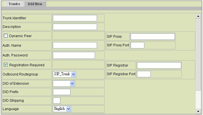
65 Chapter 4 IP PBX Configuration Figure 4-7 SIP Trunk Setup 63
66 Chapter 4 IP PBX Configuration Table SIP Trunk Configuration Settings Field Trunk Identifier Description Dynamic Peer SIP Proxy SIP Proxy Port Auth. Name Auth. Password Registration Required SIP Registrar SIP Registrar Port Outbound Routegroup 6 DID of Extension Description A unique number consisting of digits only. Usually give the phone number issued by the ITSP for consistency. Arbitrary description information. Select if the trunk is a passive trunk which means the registration will be from a dynamic remote peer. Typical application is to accept registration from an IP PBX at a remote site with dynamic IP address. Once the remote IP PBX registers, calls from local to remote can be made reversely over the trunk. Specify IP address (or fully qualified domain name) and UDP port of the remote SIP proxy, which usually refer to the SIP server on the ITSP side. Specify the name for authentication if different to the Trunk ID. Give the password used for authentication on the remote SIP proxy or registrar. Usually this is given by the ITSP. Select if registration to a registrar is required to activate the trunk. This is true for a remote IP PBX or an ITSP account, however, may be not required in case of a SIP gateway. Specify IP address (or fully qualified domain name) and UDP port of the remote SIP registrar, which usually refer to the SIP server on the ITSP side (same as proxy). Select a routegroup to associate routes with this trunk. Outbound calls match included route patterns could employ this trunk to hop onto a remote SIP domain. There may not be any appropriate routegroup to select initially. One can come back later to revise it, once the expected routegroup has been added. When enabled DID, clicks an extension in the list to be an unconditional destination for incoming calls to this trunk. Or click bynumber and then enter configurations in DID 6 Please refer to 0 for details. 64
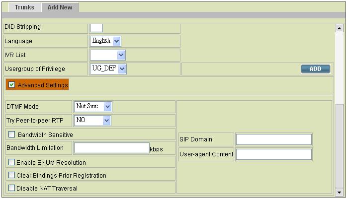
67 Chapter 4 IP PBX Configuration Field DID Prefix DID Stripping Language IVR List 7 Usergroup 8 of Privilege Advanced Settings DTMF Mode Try Peer-to-peer Description Prefix and DID Stripping to have the incoming calls directed to the corresponding extension derived by number manipulation. The SIP trunk numbers is therefore regarded as the direct line of the extension. If you set a DID extension in a trunk, then only that extension can use this trunk to call out, and all incoming calls to this trunk will connect to that extension directly. A digit string to be prefixed to the incoming called number after stripping. A number of leading digits to be stripped from the original called number. If prefix or stripping has been given but DID of Extension is not bynumber, the result of digit manipulation is dialed in a DTMF string after the call has been answered by the DID extension as an automatic 2 nd dialing. Preferred language for system instructions heard from the trunk. Associate an IVR menu with incoming calls to this trunk. This is mandatory unless the trunk is configured for DID. When disabled DID, click a usergroup in the list whose reachability to other usergroups and trunks will be used as the privilege of inbound calls from this trunk. There may not be appropriate usergroups to select initially. One can come back later once the expected usergroup has been added. Select to see more settings that is shown below. Select a preferred DTMF mode, RFC 2833 or SIP INFO, for this trunk in the list. This must match configuration on the server side. If the user does not know the DTMF mode on the server side, select Not sure from the list, and SDP will automatically detect the DTMF mode is Inband or RFC2833. Click NO to disable or IP PBX will attempt to notify the 7 Please refer to 5.12 for details. 8 Please refer to 4.2 for details. 65
68 Chapter 4 IP PBX Configuration Field Description RTP two peers in a conversation to try peer-to-peer RTP transmission. This is suggested as long as phone and ITSP side support INVITE or UPDATE method during a connected call to save the resource of IP PBX. However, only SIP INFO DTMF mode should enable this since other DTMF modes require IP PBX being RTP relay server to support in-line transfer. Bandwidth Indicate the trunk is over a bandwidth-sensitive link, e.g. Sensitive across Internet. Bandwidth Leave it blank to disable or, specifies a limit of bandwidth Limitation in kbps for call admission. SIP Domain Specify the SIP domain used by the proxy and registrar. If not specified, IP address will be used as the domain by default. User-agent Content Override default User-Agent header content. Enable ENUM Select to use ENUM resolution, or leave it as blank. Resolution Clear Bindings Prior Select if failed to the registration, and cannot identify any Registration abnormal settings. Disable NAT IP PBX uses NAT traversal for outgoing traffics by default. Traversal Select to disable NAT traversal if there is a machine that could handle NAT issues. 66
69 Chapter 4 IP PBX Configuration 4.7 FXO PSTN Trunk configuration A FXO PSTN trunk group is a logical group of one or more FXO PSTN subscriber lines connecting to FXO ports on TAINET IPBX 230. The FXO PSTN TRUNK MANAGEMENT page allows the administrator to configure PSTN trunks. Selec Trunk -> FXO PSTN Trunk, and one can add, edit and delete PSTN trunks. Go to Service -> IP PBX Service, and click RELOAD to activate changes Add a FXO PSTN Trunk Click the Add New tab. Enter settings shown in Table Click ADD. The newly added PSTN Trunk shall display in the Trunk Group Edit a FXO PSTN Trunk Click the Trunks tab, and click More to see more information.. Enter settings shown in a row of the trunk group. Click APPLY in the row to update the information Delete a FXO PSTN Trunk Click the Trunks tab, and select a trunk group. Click DEL. The deleted PSTN trunk shall disappear from the Trunk Group. 67


70 Chapter 4 IP PBX Configuration Figure 4-8 FXO PSTN Trunk Configuration Table FXO PSTN Trunk Configuration Settings Field Description Trunk Group ID number of this PSTN trunk group. A valid number ranges from 1 to 31. Trunk Ports FXO port indices grouped by this PSTN trunk, such as 1 or 1,2 or 1-3, etc. Maximum port index depends on the number of physical ports available. Description Arbitrary description information. Port Selection Click to search for an available port in the group. Asc mean is Ascending, Dsc mean is Descending. Rotating means to force ports being selected by turns to even cost. Caller ID Detection Select to detect the Caller ID calling from PSTN lines. 68
71 Chapter 4 IP PBX Configuration Field Outbound Routegroup 9 DID of Extension Language IVR List 10 Usergroup 11 of Privilege Advanced Settings Input/Output Gain Minimum Disconnection Tone Delay Before/After Answering Description Select a routegroup to associate routes with this trunk. Outbound calls match included route patterns could employ this trunk to access PSTN. There may not be appropriate routegroup to select initially. One can come back later to revise it, once the expected routegroup is added. When enabled DID, clicks an extension in the list to be an unconditional destination for incoming calls to this trunk. The PSTN numbers of the included ports are therefore regarded as the direct line numbers of the extension. If you set a DID extension in trunk, then only that extension can use this trunk to call out, and all other user s call in this trunk will connect to that extension. Preferred language for system instructions heard from the trunk. Associate an IVR menu with incoming calls to this trunk. This is mandatory unless the trunk is configured for DID. When disabled DID, click a usergroup in the list whose reachability to other usergroups and trunks will be used as the privilege of inbound calls from this trunk. There may not be any appropriate usergroups to select initially. One can come back later to revise it, once the expected usergroups are added. Select to see more settings shown below. Voice amplification or attenuation in db scale to adjust input/output volume of a PSTN line. Minimum volume level of the disconnection tone. If a PSTN trunk is found to have disconnection problem and voice sounds low, choose a lower db. Delay in seconds before and after answering a call from PSTN trunk. 9 Please refer to 0 for details. 10 Please refer to 5.12 for details. 11 Please refer to 4.2 for details. 69
72 Chapter 4 IP PBX Configuration 4.8 Terminal Trunk Configuration A SIP trunk terminal refers to a SIP account for a remote SIP trunk to register with. It terminates SIP registration and invitation from a remote IP PBX and relay calls to local clients, PSTN trunks, or further SIP trunks. In a site-to-site SIP trunking application, a SIP trunk on one side usually pairs with a trunk terminal on the other side to form a unidirectional call hand-off path. To allow trunking in the other direction, the two sides swap roles and form another pair. Since a trunk terminal is the account for a SIP trunk to authenticate with, exact the same identifier and password must be used for both. The TERMINAL TRUNK MANAGEMENT page allows the administrator to configure trunk terminals used by TAINET IPBX 230. Select Trunk -> Terminal Trunk, and one can add, edit and delete terminals. Go to Service -> IP PBX Service, and click RELOAD to activate changes Add a Terminal Trunk Click the Add New tab. Enter settings shown in Table Click ADD. The newly added terminal shall display in the Terminal Identifier Edit a Terminal Trunk Click the Trunks tab, and More to see more information. Edit settings shown in in a row. Click APPLY in the row to update the information Delete a Terminal Trunk Click the Trunks tab, and select a terminal identifier. Click DEL. 70

73 Chapter 4 IP PBX Configuration The deleted terminal trunk shall disappear from the Terminal Identifier. Figure 4-9 Trunk Terminal Setup Table Trunk Terminal Configuration Settings Field Terminal Identifier Description Terminal Password Language Usergroup 12 of Privilege Bandwidth Sensitive Bandwidth Limitation Description A unique number consisting of digits only. This is the trunk identifier configured on the other IP PBX. Arbitrary description information. Password of SIP trunk given on the other IP PBX for authentication. Preferred language for system instructions heard from the terminal. When disabled DID, click a usergroup in the list whose reachability to other usergroups and trunks will be used as the privilege of inbound calls from this terminal. There may not be any appropriate usergroups to select initially. One can come back later, once the expected usergroup has been added. Indicate the trunk is over a bandwidth-sensitive link, e.g. across Internet. Leaves this blank to disable or, specifies a limit of bandwidth in kbps for call admission. 12 Please refer to 4.2 for details. 71

74 Chapter 4 IP PBX Configuration 4.9 POTS Setting This page allows selection of country-based progress tones and/or impedance and/or compact type of POTS ports. Click APPLY to save modifications. Go to Service -> IP PBX Service, and click RESTART to active new settings. Figure 4-10 POTS Setting 72

75 Chapter 5 Feature Configuration Chapter 5. Feature Configuration A feature is a logical entity presenting a function module of IP PBX, e.g. meet-me conference, auto attendant, voice mail, music on hold, etc. Any configuration change to a feature requires clicking RELOAD in Service -> IP PBX Service to take effect. 5.1 Call Park During a call, the callee may want to continue the conversation using another phone. The call park feature enables so by letting the callee transfer the call to the call park pilot number. IP PBX will respond an available park line from the pool of call park numbers to the callee. After that the callee may hang up current phone, move to another phone, and dial the park line number told by IP PBX to resume conversation with the caller. If the callee does not call the given park line number to retrieve his call before timeout, IP PBX will ring the original extension where the callee answered the call. To configure Call Park feature, select Feature -> Call Park. Enter settings shown in Table Click APPLY. Figure 5-1 Call Park Management Table Call Park Configuration Settings Field Description Call Park Pilot Number A unique extension number for call parking, e.g Available Parking Lines An extension pool for call parking, e.g forms a 20-line pool available for system to park calls. Parking Timeout Timeout waiting for picking up the parked call 73

76 Chapter 5 Feature Configuration 5.2 Life Line Life line feature allows specification of emergency number patterns to seize a PSTN line with absolute priority. For example, someone dials an emergency call while all PSTN lines are in use. In such case, if the called number matches any specified life line pattern, the PSTN line with longest talk time so far will be disconnected right away to allow the emergency call. Select Feature -> Life line to configure life-line feature Add a Life Line Pattern Enter settings shown in Table Click ADD. The newly added pattern should display in the Line Pattern Delete a Life Line Pattern Select a Line pattern. Click DEL. The deleted pattern shall disappear from the Line Pattern. Figure 5-2 Life Line 74
77 Table Life line Configuration Settings Chapter 5 Feature Configuration Field Line Pattern Description Description Pattern for emergency numbers. Note: this is the pattern after digit stripping. For example, configure 911 here even if users dial 9911 to reach the 911 service over PSTN when the PSTN trunk has an outbound dialplan of 9.. Arbitrary description information. 75
78 Chapter 5 Feature Configuration 5.3 Meet-me Conference Meet-me conference enables conferencing of multiple parties from various sources. A party could dial in a conference from an internal IP phone, an external IP phone on Internet, an analog phone via PSTN, or an IP phone behind another IP PBX. TAINET IPBX 230 allows multiple conference rooms going concurrently using different room numbers. Before entering a meeting room, the caller has to enter the correct PIN of the room number. Note: The administrator who invited another meet-me conference room must drop all parties by pressing *5 when the meeting ends. Select Feature -> Meet-me Conference to configure meet-me conference feature Add a Meet-me Conference Enter settings shown in Table Click ADD to add a new conference room. The newly added room should display in the Room Number Edit a Meet-me Conference Edit settings shown in a row. Click APPLY at the end of the row to update the information Delete a Meet-me Conference Select a room number. Click DEL. The deleted conference room shall disappear from Room Number. 76
79 Chapter 5 Feature Configuration Figure 5-3 Meet-me Conference Table Meet-me Conference Configuration Settings Field Description Room Number Meeting room number, e.g Description Arbitrary description information. PIN to Join PIN for normal users to join the conference. During a conference, a normal user has following options: # to quit conference *1 to mute/unmute *9 to log in as the administrator if there is no administrator dialed in yet. Administrator PIN for the administrator of the conference. PIN During a conference, the administrator has following options: # to quit conference *1 to mute/unmute *2 to lock/unlock the conference *3 to invite a user into the conference *4 to drop a party from the conference *5 to drop all parties in the conference *6 to drop the last invited party by *3 ** to send DTMF string to the last invited party by *3. This is useful when the invited party is behind an IVR system. 77
80 Chapter 5 Feature Configuration 5.4 Music On Hold Music-on-hold (MOH) is used in several occasions for a single purpose to comfort the waiting party with music. One could upload some candidate music files and pick one as the default one. Select Feature -> Music On Hold to manage MOH files Add a MOH File Enter settings shown in Table Click ADD. The newly added file should be displayed in the MOH ID column Edit a MOH File Edit settings shown as a table at the bottom of the page. Click APPLY in the row Delete a MOH File Select a MOH ID. Click DEL at the top-left the table. The deleted MOH file shall disappear from the MOH ID column. 78

81 Chapter 5 Feature Configuration Figure 5-4 Music On Hold Table MOH file Configuration Settings Field MOH ID Media File Default MOH Description A unique ID containing only alphabets, numbers, and underscore without spaces; 32 characters maximum. Candidate music files in the repository. To upload a new music file, click Browse to find a Windows PCM (8000 Hz, 16-bit) file from the local host and click PUT FILE. On successful uploading, the filename will appear in the Media File list. To delete a media file from the list, choose a file from the Delete Media File list, and click DEL to remove it. Select to use this music file for system default MOH globally. 79

82 Chapter 5 Feature Configuration 5.5 Voic TAINET IPBX 230 has a built-in voice mail subsystem with a sophisticated IVR menu. A call to an extension in use or no answer could be configured to enter voice mail recording procedure. After leaving a message, notification will be sent to the user owns the extension with or without the message in the form of an attached WAV file. The Message Waiting Indicator (MWI) on phone (if any) will be lit. The user could then dial the voic pilot number to enter voice mail system to manage messages such as playback, delete, or move them from inbox to different folders. In addition to indicating current voice mail capacity on the management page, IP PBX can send an alarm to the administrator when the available voice mail space reaches the threshold. To configure Voic feature, select Feature -> Voic . Enter settings shown in Table Click APPLY. Figure 5-5 Voic Prompts Management Table Voice Mail Configuration Settings Field Voic Pilot Number Minimum Message Time Maximum Message Time Maximum number of messages per account SMTP Server from Address Description Number to access voice mail system IVR. Messages less than this duration will not be notified by . E.g., 3 (sec). Maximum duration allowed for a single message. E.g., 60 (sec). Maximum number of messages allowed per extension. Hostname or IP address of the SMTP server for voic notification. Most SMTP servers require a valid from address to accept a mailing request. 80
83 Chapter 5 Feature Configuration Field Voic Available Space Check Send Alarm when Space Below Voic Space Left SMTP Server Account SMTP Server Password Description Select to enable the Alarm function described below. Set a threshold in minutes to send an alarm to the administrator when the space left is below it. Show the available space in Kbytes and minutes. The storage inside IP PBX saves not only voice mails but also some other stuff, such as CDR and logs. The remained disk space is all for voice mails, and it is the maximum available voice mail space. Specify an account ID if the SMTP server requires authentication for outgoing mails. Specify the account password if the SMTP server requires authentication for outgoing mails. Note: 1 Mega bytes memory can store about 2 minutes. And we suggest the format of the USB must be FAT32 81

84 Chapter 5 Feature Configuration 5.6 Meet-me Prompts This page allows replacing built-in meet-me conference prompts with user recordings. Click a language and a prompt in the corresponding lists. Find a corresponding recording in the local storage. Click PUT FILE to complete the replacement. To reset a prompt back to default, leave the Upload box in blank and directly click the PUT FILE. Note that the replacement is done for the selected Language and Prompt only. Currently only following prompts could be replaced. Figure 5-6 Meet-me Prompt Management Table Replaceable Meet-me Prompts Prompt Get PIN number Invalid PIN Only Person Description Please enter the conference pin number. That pin is invalid for this conference. You are currently the only person in this conference. 82

85 Chapter 5 Feature Configuration 5.7 Voic Prompts This page allows replacing built-in voic system prompts with user recordings. Click a language and a prompt in the corresponding lists. Find a corresponding recording in the local storage. Click PUT FILE to complete the replacement. To reset a prompt back to default, leave the Upload box in blank and directly click PUT FILE. Note that the replacement is done for the selected Language and Prompt only. Currently only following prompts could be replaced. Figure 5-7 Voic Prompts Management Table Replaceable Voic System Prompts Prompt Login Password Incorrect Mailbox Good-bye Prerecording Introduction Introduction Description Welcome to voice mail system, please enter your mailbox. Password. Login incorrect, mailbox? Good-bye. Press star (*) to cancel recording and return to the main menu. Or, press pound (#) to start recording right away. Please leave your message after the tone. When done, hang up or press the pound (#) key. 83
86 Chapter 5 Feature Configuration 5.8 Broadcast A User can arrange an event at the exact time in IP PBX. IP PBX will inform all users that set in the Callee Extensions list by ringing their extensions. For example, one arranges a meeting and wants to remind all attendants, he/she may enter settings. When the time set in Date/Time is up, IP PBX will call to the extensions, and then executes the Action to each of the calls. Select Feature -> Broadcast to configure Broadcast feature Add a Broadcast Click the Add New tab. Enter settings shown in Table Click ADD at the bottom of the page. The newly added broadcast event should display in the Events Edit a Broadcast Click the Management tab. Click an Event. Edit settings shown in Table Click UPDATE to update the information Delete a Broadcast Click the Management tab. Select an Event. Click DEL. The deleted broadcast event shall disappear from the Events. 84

87 Chapter 5 Feature Configuration Figure 5-8 Broadcast Management Table Broadcast Configuration Settings Field Event Action Upload File Dial Extension Max Retry Times Retry Time Wait Time Description A unique ID containing alphabets, numbers, and underscore only without spaces; 32 characters maximum. Select one of the three actions to execute when the Date/Time is up. Playback: Play the uploaded WAV file in the Upload File box to the callee extensions. Dial: IP PBX will ring the party set in the Callee Extensions box first, and then call back to the one in the Dial Extension field to establish a conversation. It is suggested to set one number only in the Callee Extensions unless the extension number in the Dial Extension field is multi-line. MusicOnHold: Play default music to extensions in the Callee Extensions box. Upload a *.wav file, if Playback is selected in the Action list. The recording format must be 8000 Hz, 16 bits, Windows PCM WAV file. Select an extension to call back if Dial is selected as the Action. Maximum redial times if callees did not answer. A period of time in minutes between two retrying. Enter timeout in seconds when ringing a callee. 85
88 Chapter 5 Feature Configuration Field Date/Time Callee Extensions Description Select a Date/Time to trigger this broadcast event. Intended extensions to be called at the Date/Time. 86
89 Chapter 5 Feature Configuration 5.9 Worktime Worktime defines holidays and business hours for auto attendant or generic IVR application. Several groups of date/time could be defined for different IVR menus. The worktime must collocate with IVR settings. Select Feature -> Worktime to configure Worktime features Add a Worktime Click the Add New tab. Enter settings shown in Table Click ADD at the bottom of the page. The newly added worktime should display in the Group ID Edit a Worktime Click the Management tab. Click a Group ID. Edit settings shown in Table Click UPDATE to update the information Delete a Worktime Click the Management tab. Select a Group ID. Click DEL. The deleted worktime shall disappear from the Group ID. 87

90 Chapter 5 Feature Configuration Figure 5-9 Worktime Management Table Worktime Configuration Settings Field Group ID Mode General Worktime Saturday Worktime Optional Worktime Description A unique ID containing numbers only. Select one of the three modes: 1: No work on weekends. 2: Work off and on by turns for weekends 3: Work half-day on Saturdays. The work time from Monday to Friday. The work time for Saturdays, this field only active when mode is set to 2 or 3. Special holidays or workday. User can set date and its work time, or set it to a whole-day holiday. 88
91 Chapter 5 Feature Configuration 5.10 Memo Call A user can set a memo at a specific time, e.g. a morning call, in IP PBX to inform the user or another user set in the Extension list by call at the time. When the user picks up the phone, IP PBX plays voice file or music. The user can also set this memo as a daily route so that IP PBX informs the user at the exact time every day. Select Feature -> Memo Call to configure memo calls Add a Memo Call Click the Add New tab. Enter settings shown in Table Click ADD at the bottom of the page. The newly added memo call should display in the Memo Edit a Memo Call Click the Management tab. Click a Memo. Edit settings shown in Table Click UPDATE to update the information Delete Memo Call Click the Management tab. Select a Memo. Click DEL. The deleted memo call shall disappear from the Memo. 89

92 Chapter 5 Feature Configuration Figure 5-10 Memo Call Managment Table Memo Configuration Settings Field Memo Extension Repeat Daily Action Upload File Max Retry Times Retry Time Wait Time Date/Time Description A unique ID containing alphabets, numbers, and underscore only without spaces. Click an extension to call. Select Yes to enable looping playback every day at the exact time. Select one out of the two available actions for the memo. Playback: Play the uploaded WAV file in the Upload File box to the extension(s). MusicOnHold: Play default music to the extension(s). Upload a *.wav file, if Playback is selected in the Action list. The recording format must be 8000 Hz, 16 bits, Windows PCM WAV file. Maximum redial times if callees did not answer. A period of time in minutes between two retries. Enter timeout in seconds when ringing a callee. Select a Date/Time to trigger this memo call. 90
93 Chapter 5 Feature Configuration 5.11 Automatic Call Distribution TAINET IPBX 230 implements Automatic Call Distribution (ACD) by queues and agents. A pool of agents is created first and then one or more queues could be added with distinct service numbers and a list of agent extensions. Each agent should be bound with an existed extension to take calls and each queue could have a specific distribution policy, such as round robin, ring all, least recent, fewest calls, and random. With such settings one can enable agents located at any location to serve a unified queue of calls. This comes with a benefit that administrative changes can be made in a single place, and these changes immediately become effective for all calls and all agents. This not only enables distributed centers to be operated cost-effectively, but also reduces the cost and complexity of implementing home-based agents, who now only need an IP connection to serve calls in queues. Refer to Table for creating an agent pool, and Table for setting queues. Select Feature -> ACD to configure agents and queues Set Agent Login and Logout Before add agents or queues of the ACD, the administrator has to give universal Agent Login and Logout numbers for all agents. Click the Agent Login / Logout tab. Enter numbers in Agent Login and Agent Logout. Click MOD to apply login and logout numbers to all agents Add an Agent or a Queue Click the Add New tab. Enter settings shown in Table and Table Click ADD at the bottom of the page. The newly added agent or queue should display in the Management page. 91
94 Chapter 5 Feature Configuration Edit an Agent or a Queue Click the Management tab. Click a queue or an agent in Queue or Agents. Edit settings shown in Table for the queue or Table for the agent. Click UPDATE to update the information. 92

95 Chapter 5 Feature Configuration Delete an Agent or a Queue Click the Management tab. Click a bottom of the row. Click DEL. The deleted agent or queue shall disappear from the Management page. Figure 5-11 Add new settings Table Agent Configuration Settings Field Agent Name Account PIN Description Name the agent. A unique ID containing alphabets, numbers, and underscore only without spaces; 32 characters maximum. Enter an account number for the agent. Enter a login password for the agent. Table Queue Configuration Settings Field Queue Name Description Name a queue. A unique ID containing alphabets, numbers, and underscore only without spaces; 32 characters maximum. 93
96 Chapter 5 Feature Configuration Field Description Waiting Music The music to be played before any agent answers the call. Distribution Policy Ways of distributing calls to the agents in a queue: Round Robin: take turns to ring each available agent. Ring All: ring all available agents until one answer (default). Least Recent: ring the agent that was least recently called in this queue. Fewest Calls: ring the agent with fewest completed calls in this queue. Random: ring the agents randomly. User Group Select a usergroup for this queue. Timeout Set a timeout period in seconds when no agent answers the call. The time must be longer than Timeout To Next Forward of the extension, or the call will forward to an extension that is set in Unavailable Call Forward in Extension of IP Phone. Retry Time Set a waiting time in seconds to ring agents in the queue again if the call is not answered. Service Extension Set the representative number of this queue, e.g. a queue named Support, and its service extension is 500. There are three agents with extensions of 155, 157, and 166 in Support. The Distribution Policy is set to Ring All. When a customer calls the service extension 500 for Support, extensions 155, 157 and 166 will all ring simultaneously. Agent List Click ADD/DEL to select/remove agents belonged to this queue. The left box lists the available agents, and the right box shows the selected agents. 94
97 Chapter 5 Feature Configuration 5.12 Interactive Voice Response (IVR) Interactive Voice Response (IVR) helps a caller to select options from voice menus by pressing keys on a telephone keypad. With IVR, a caller can connect to an expected extension or a service promptly. TAINET IPBX 230 enables multiple configurable IVR menus in a single system, and each of them could have a hierarchy up to three layers. Select Feature -> IVR to add, edit and delete the IVR menus. You can also manage IVR prompts, used by IVR menus, in this page Add a new IVR Menu Enter a name of an IVR menu in IVR Name, and click a file in the Prompt list. Click ADD next to the IVR Name box to set the new IVR name in Info. System will prompt to ask for confirmation whether a Worktime setting is required or not. This is because Worktime setting can only be added when creating a new IVR. After creation, an IVR without Worktime setting cannot be associated with a Worktime setting later. If Worktime setting is indeed not required, click Cancel in the popped dialog. Enter settings shown in Table Click APPLY to add the new IVR menu and see it as a tree view in Info. For example, to create a basic Auto Attendant IVR for a trunk with Usergroup of Privilege dial_in: Specify an IVR Name, say Basic_AA Choose */agent-newlocation.gsm from Prompt list in Action Data block. Choose dial_in from Group in Action Data block. Click the ADD button beside the given IVR Name, Basic_AA. Click Cancel to the popped dialog window to confirm Worktime setting is not required. Now, Basic_AA should be available in the trunk configuration page for IVR setting. 95
98 Chapter 5 Feature Configuration Edit an IVR Menu Click an IVR name in the All IVR Menus list. Edit settings shown in Table Click APPLY to update the changes Delete an IVR Menu Click an IVR name in the All IVR Menus list. Click DEL to delete the IVR menu. Table 5.12 Interactive Voice Response Configuration Settings Field All IVR Menus Info IVR Name Rule Node Child Rule Action Data Description Select a preferred IVR menu name. View the IVR menu as a tree view. Specify the name of the IVR. Click a number in the Keypad list and one of the following actions in the Action list to associate an action with a key. Hang Up To cut off the call immediately. Play Back To play the IVR prompt selected in Prompt list Call To To call an extension. Go to Top To go back to the root menu of the IVR. Next Layer To go to the next layer of the IVR menu. Select To choose a language. Language Return To go back to the previous layer. Information of the configured keys and actions. Click a node and DEL to delete the node and its underlying structure. If a Next Layer is selected, Child Rule sets the key-action associations with the next-layer menu. Specify applicable parameter(s) for an action. 96
99 Chapter 5 Feature Configuration Field Active Worktime Group In-Hour Actions Prompt Extension Description Prompt Select a *.wav recording file that you add from the IVR Prompt tab, or select one of the following default voice file. The default file that marked */ in front of the file name means this voice file provides all languages that IP PBX has for you to select. Please click a language in the Languages list. agent-newlocation.gsm: Please enter a new extension followed by the # key. auth-thankyou.gsm: Thank you. invalid.gsm: I'm sorry, that is not a valid extension, please try again. transfer.gsm: Please hold while I try out that extension. ss-busy.gsm: System is busy at this moment, please try again later. ss-noservice.gsm: The number you have dial is not in service, please check the number and try again. vm-goodbye.gsm: Good bye. vm-sorry.gsm: I'm sorry, I do not understand you response. Group Select a usergroup. Language Select a language of the IVR. Extension Enter an extension number to be transferred to. Select to set work time for the IVR. Select a work time group set in Feature -> Worktime. Select one action during business hours. Play Back To play the selected prompt. Call To To transfer to an extension No Action No action. Select a *.wav file if Playback is selected in the In-Hour Actions list. Enter an extension number if Call To is selected in the In-Hour Actions list. 97
100 Chapter 5 Feature Configuration Field Off-Hour Actions Prompt Extension Description Select one action during the off hours. Play Back To play the selected prompt. Call To To transfer to an extension No Action No action. Select a *.wav file if Playback is selected in the Off-Hour Actions list. Enter an extension number if Call To is selected in the Off-Hour Actions list IVR Prompts Management One can upload customized IVR prompts in Feature -> IVR, and click IVR Prompts Management tab Add an IVR Prompt Select a language from the Language list. Click Browse to find the expected recording in the local storage. Click PUT FILE to upload the file add it to the Prompt list Delete an IVR Prompt Select a *.wav file from the All Files list. Click DEL. The deleted file shall disappear from the All Files list. 98
101 Chapter 6 Example Provisioning Chapter 6. Example Provisioning This chapter introduces several practical configuration examples of TAINET IPBX 230 deployment. The configuration of TAINET IPBX 230 is very flexible and the expressiveness of usergroups, routegroups and trunks are scalable enough to support various network architectures. Users could refer to these examples and build a larger network involving multiple sites and advanced services. 6.1 Internal Extension Configuration The procedure introduced below is recommended as the first step of a configuration task. The configuration only enables internal extension calls, but it serves as a good practice for administration. User can fllow the steps asfigure 6-1. Configure a usergroup named ALL (refer to 4.2). Configure users and assign every user to usergroup ALL (refer to 4.1). Configure devices and an extension for each device (refer to 4.3). Assign each extension to a corresponding user (refer to 4.3). Configure each client phone with respect to the extension number and password in its IP PBX extension configuration accordingly. Reload the IP PBX service (refer to 3.5.2). Up to this point all configured phones should register with the IP PBX with a usable extension. Since these phones are all belonged to the same usergroup ALL, they can call one another without limitation. 99

102 Chapter 6 Example Provisioning Figure 6-1 Settings Roadmap 100

103 Chapter 6 Example Provisioning 6.2 Case I: Single-site Configuration This case describes the typical settings of a single-site configuration; say Company A. Assume Company A has a DSL connection for Internet access and 2 PSTN subscriber lines as shown in Figure 6-1. The provisioning tasks include: Figure 6-2 Single side Setup topology There are staff phones in cubes and offices, and utility phones in public areas. Each phone has one extension, and can call any extension without limitation. Only staff phones can call out to PSTN with a prefix 9. Incoming PSTN calls are answered by auto attendant and could be transferred to any extension. Configuration steps: Create usergroups named staff, utility, and ext-all. Add staff and utility in the Reachable User Groups of ext-all. Create a user account for each staff and assign it to usergroup staff. Create an additional user account named public and assign it to usergroup utility. Create a device for each physical phone and designate an extension. 101
Internet Telephony PBX System IPX-1800 User s Manual
 Internet Telephony PBX System IPX-1800 User s Manual 1 of 49 FCC Notice This equipment has been tested and found to comply with the limits for a Class A digital device, pursuant to Part 15 of FCC Rules.
EP502/EP504 IP PBX 1.1 Overview
 1.1 Overview The EP502/EP504 is an embedded Voice over IP (VoIP) Server with Session Initiation Protocol (SIP) to provide IP extension phone connection for global virtual office of small-to-medium business
VOI-9200 SIP IP PBX User Manual
 VOI-9200 SIP IP PBX User Manual Ver. 1.01-0701 Table of Contents 1. INTRODUCTION... 3 1.1. OVERVIEW... 3 1.2. FEATURE... 4 1.3. PACKAGE CONTENT... 5 1.4. PHYSICAL... 5 1.5. DEFAULT SETTINGS... 7 1.6. CONNECTION
4 Port IP-PBX + SIP Gateway System
 4 Port IP-PBX + SIP Gateway System The IPG-40XG is an embedded Voice over IP (VoIP) PBX Server with Session Initiation Protocol (SIP) to provide IP extension phone connections for global virtual office
ONU 852, 853. PON ONU series. User Manual
 User Manual PON ONU series ONU 852, 853 Headquarters: No. 25, Alley 15, Lane 120, Sec. 1. Nei-Hu Rd, Taipei 114, Taiwan TEL: 886-2-26583000 FAX: 886-2-26583232 Version: 1.0 Date: 2007/11/16 P/N: 07008-00106
SoLink-Lite IP-PBX. Administrator Guide. (Version 1.0)
") SoLink-Lite IP-PBX Administrator Guide (Version 1.0) TABLE OF CONTENT 1.0 Introduction... 1 2.0 Setting Up the IP-PBX... 2 3.0 Logging On... 3 4.0 Configuring Network... 4 5.0 Configuring Hardware... 5
SoLink-Lite IP-PBX Administrator Guide (Version 1.0) TABLE OF CONTENT 1.0 Introduction... 1 2.0 Setting Up the IP-PBX... 2 3.0 Logging On... 3 4.0 Configuring Network... 4 5.0 Configuring Hardware... 5
ANSEL FXS / 1 PSTN. VoIP Telephone Adaptor. User Manual V1.10
 ANSEL 5518 1 FXS / 1 PSTN VoIP Telephone Adaptor User Manual V1.10 Quick Guide Step 1: Broadband (ADSL/Cable Modem) Connections for ANSEL 5518 A. Connect ANSEL 5518 WAN port to ADSL NAT Router as the following
Welltech WellGate User Manual
 Welltech WellGate 2626 An Easy to Use PBX Gateway User Manual Copyright 2009 Welltech Computer Co., Ltd. All right reserved Table of Contents Introduction...2 WellGate 2626 - An Easy to Use PBX Gateway...2
RP-FSO522 2-Line FXO, 2-Line FXS SIP IP Gateway. Feature
 RP-FSO522 2-Line FXO, 2-Line FXS SIP IP Gateway RP-FSO522 is an 2-Line FXO plus 2-Line FXS gateway with SIP protocol IP device which allows to connect 2 Lines of analog PSTN telephone line and connect
USER GUIDE. IP PBX Telephony System
 USER GUIDE SMCPBX10 TM TigerVoIP IP PBX Telephony System IP PBX Telephony System User Guide The easy way to make all your network connections 20 Mason Irvine, CA 92618 Phone: (949) 679-8000 E112007-EK-R01
TT11 VoIP Router 1FXS/1FXO TA User Guide
 TT11 VoIP Router 1FXS/1FXO TA User Guide Page 1 Table of Contents: 1.0 Introduction... 3 2.0 Package Contents... 3 3.0 Summary of LED & Connector Descriptions... 4 3.1 The Front LEDs... 4 3.2 The Rear
What you need today is Essence IPBX for tomorrow s productivity
 What you need today is Essence IPBX for tomorrow s productivity Energize your business with effective Essence IPBX system which comes with easy setup and administrator-friendly designs. Essence IPBX system
Internet Telephony PBX System IPX Quick Installation Guide
 Internet Telephony PBX System IPX-2000 Quick Installation Guide Overview PLANET IPX-2000 is the next generation voice communication platform for the small to medium enterprise. Designed as an open, scalable,
End User Guide Cloud PBX
 End User Guide Entrust ICT(EICT) reserves the right to change product specifications, functions, or features, at any time, without notice. Please refer to your EICT representatives for further details.
Version: epbxum_
 epbx-100a-128 User s Manual Version: epbxum_128.300 CH1. Overview 5 1.1 Specifications 5 1.2 Hardware Overview 7 1.2.1 Front Panel and LED Indication...7 1.2.2 Back Panel...8 CH2. Start to configure epbx-100a-128
Version: SIPPBXUM.100
 SIPPBX 6200A User s Manual Version: SIPPBXUM.100 CH1. Overview... - 5-1.1 Specifications... - 5-1.2 Hardware Overview... - 8-1.2.1 The Front Panel... - 8-1.2.2 The Back Panel... - 8 - CH2. Start to configure
SPA400 Internet Telephony Gateway with 4 FXO Ports
 SPA400 Internet Telephony Gateway with 4 FXO Ports Administration and Configuration Guide v1.0 Using the SPA400 The SPA400 features the ability to connect up to four (4) standard analog telephones lines
Setting Up an Alcatel 4400 Digital PIMG Integration with Cisco Unity Connection
 up Alcatel 4400 Digital PIMG Integration with Cisco Unity Connection Up an Alcatel 4400 Digital PIMG Integration with Cisco Unity Connection, page 1 Up an Alcatel 4400 Digital PIMG Integration with Cisco
Setting up Alcatel 4400 Digital PIMG Integration
 up Alcatel 4400 Digital PIMG Integration with Cisco Unity Connection Up an Alcatel 4400 Digital PIMG Integration with Cisco Unity Connection, on page 1 Up an Alcatel 4400 Digital PIMG Integration with
8-Port SIP VoIP Gateway (8 FXS)
") 8-Port SIP VoIP Gateway (8 FXS) Highlights Supports SIP 2.0 (RFC 326) Supports IPv6 and IPv4 simultaneously Up to 24 SIP service domains and Caller ID Supports auto HTTP provision and fax feature Flexible
8-Port SIP VoIP Gateway (8 FXS) Highlights Supports SIP 2.0 (RFC 326) Supports IPv6 and IPv4 simultaneously Up to 24 SIP service domains and Caller ID Supports auto HTTP provision and fax feature Flexible
Please follow the steps that are listed here to get started with your Berkshire 10K ippbx telephone system.
 Please follow the steps that are listed here to get started with your Berkshire 10K ippbx telephone system. Step 1 Power-up and log into your PC. Unplug any existing ethernet cable from your PC. Step 2
Application Notes for Configuring the ADTRAN NetVanta UC Server with Avaya IP Office 6.1 Issue 1.0
 Avaya Solution & Interoperability Test Lab Application Notes for Configuring the ADTRAN NetVanta UC Server with Avaya IP Office 6.1 Issue 1.0 Abstract These Application Notes describe the procedure for
Setting Up a Mitel SX-2000 Digital PIMG Integration with Cisco Unity Connection
 Up a Mitel SX-2000 Digital PIMG Integration with Cisco Unity Connection Up a Mitel SX-2000 Digital PIMG Integration, page 1 Up a Mitel SX-2000 Digital PIMG Integration Task List for Mitel SX-2000 PIMG
VG422R. User s Manual. Rev , 5
 VG422R User s Manual Rev 1.0 2003, 5 CONGRATULATIONS ON YOUR PURCHASE OF VG422R... 1 THIS PACKAGE CONTAINS... 1 CONFIRM THAT YOU MEET INSTALLATION REQUIREMENTS... 1 1. INSTALLATION GUIDE... 2 1.1. HARDWARE
IS-381 / IS-382 IP Audio gateway. User Manual
 IS-381 / IS-382 IP Audio gateway User Manual IS-381 IS-382 PORTech Communications Inc. Content 1. Introduction... 1 2. Functions... 1 3. Parts list... 2 4.Main body size... 2 5.Panel description... 3 6.Link
SVG300S+ 2 FXS SIP/IAX ATA USER MANUAL
 SVG300S+ 2 FXS SIP/IAX ATA USER MANUAL STEPHEN TECHNOLOGIES CO.,LIMITED ALL RIGHTS RESERVED Contents Preface... 3 About this Manual... 3 Audience... 3 Related Documentation... 3 Document Conventions...
2757 VoIP Phone Users Guide
 2757 VoIP Phone Users Guide Rev. 1.0 Table of Contents 1 Introduction... 5 1.1 Package Contents... 5 1.2 Features... 5 1.3 Basic Setup... 6 2 Network Setup... 8 2.1 Static IP Address... 8 2-2 PPPoE...11
Setting Up a Serial (SMDI, MCI, or MD-110) PIMG Integration with Cisco Unity Connection
 PIMG Integration with Cisco Unity Connection") CHAPTER 11 Setting Up a Serial (SMDI, MCI, or MD-110) PIMG Integration with Cisco Unity Connection For detailed instructions for setting up a serial (SMDI, MCI, or MD-110) PIMG integration with Cisco Unity
CHAPTER 11 Setting Up a Serial (SMDI, MCI, or MD-110) PIMG Integration with Cisco Unity Connection For detailed instructions for setting up a serial (SMDI, MCI, or MD-110) PIMG integration with Cisco Unity
Analog Telephone Adapter Setup for Q-SYS Softphone
 Analog Telephone Adapter Setup for Q-SYS Softphone This document applies to this Cisco device: SPA232D Introduction This document covers the use of the SPA232D in the role of analog telephone adapter (ATA)
ICE-008 IP PBX. 1 Product Information 1.1 New Mini PBX. 1.2 Features System Features Call Handling Features
 ICE-008 IP PBX 1 Product Information 1.1 New Mini PBX ICE008 is a new generation office communication equipment that delivers traditional PBX (private branch exchange) functions and more with advanced
 IPX Voice Communication Features and Services Auto Attendant Direct Inward Dialing (DID) Auto CO Line Hunting Multi Operator Hunting PBX/ATA Dial Plan Speed Call Short Number Life Line Custom Define Call
ATCOM IPPBX IP01 Product Guide Version: VoIPon Tel: +44 (0) Fax: +44 (0)
 Fax: +44 (0)") Figure: ATCOM IPPBX IP01 ATCOM IPPBX IP01 Product Guide Version: 1.0 2010-05-10 Content CONTACT ATCOM... 3 CHAPTER 1 THE INTRODUCTION OF IP01... 4 CHAPTER 2 ACCESS TO THE IP01... 6 2.1 WEB PAGE ACCESS
Figure: ATCOM IPPBX IP01 ATCOM IPPBX IP01 Product Guide Version: 1.0 2010-05-10 Content CONTACT ATCOM... 3 CHAPTER 1 THE INTRODUCTION OF IP01... 4 CHAPTER 2 ACCESS TO THE IP01... 6 2.1 WEB PAGE ACCESS
EIP 7012 Essence VoIP Phone Administration Guide Version 1.0B
 Essence Technology EIP 7012 Essence VoIP Phone Administration Guide Version 1.0B Table of Contents 1 Introduction... 1 1.1 Hardware Overview... 1 1.2 Software Overview... 1 2 Keypad interface for IP Phone
Sipura SPA 3000 How To. (c) Bicom Systems
 Bicom Systems") Sipura SPA 3000 How To Sipura SPA 3000 How To All rights reserved. No parts of this work may be reproduced in any form or by any means - graphic, electronic, or mechanical, including photocopying, recording,
Sipura SPA 3000 How To Sipura SPA 3000 How To All rights reserved. No parts of this work may be reproduced in any form or by any means - graphic, electronic, or mechanical, including photocopying, recording,
Cisco Unified Communications UC320W Pre-Installation Site Information
 Cisco Unified Communications UC320W Pre-Installation Site Information Use this workbook to gather information from your customer before you install the Cisco Unified Communications UC320W at the site.
Setting Up an Avaya Definity ProLogix Digital PIMG Integration with Cisco Unity Connection
 CHAPTER 4 Setting Up an Avaya Definity ProLogix Digital PIMG Integration with Cisco Unity Connection For detailed instructions for setting up an Avaya Definity ProLogix digital PIMG integration with Cisco
UCM6102/6104/6108/6116 Configuration
 UCM6102/6104/6108/6116 Configuration This document introduces manual configuration steps performed for interoperability testing between AccessLine and Grandstream UCM6102/6104/6108/6116. Configuration
IPNext 187 Hybrid IP-PBX System High-performance Hybrid IP-PBX Solution
 IPNext 187 Hybrid IP-PBX System High-performance Hybrid IP-PBX Solution IP-PBX Features www.addpac.com AddPac Technology 2011, Sales and Marketing Contents IP-PBX Features Smart Multimedia Manager VoIP
VG-422R. User s Guide
 VG-422R User s Guide Trademarks Contents are subject to revise without prior notice. All trademarks belong to their respective owners. FCC Warning This equipment has been tested and found to comply with
CUCM XO SIP Trunk Configuration Guide
 QUANTiX QFlex Session Border Controller CUCM 10.0 - XO SIP Trunk Configuration Guide Release 5.6.2-9 Document revision: 01.01 www.genband.com 2 630-02102-01 QUANTiX QFlex Session Border Controller Publication:
UCM6100 Series IP PBX Firmware Release Note
 UCM6100 Series IP PBX Firmware Release Note Table of Content FIRMWARE VERSION 1.0.10.39... 2 PRODUCT NAME... 2 DATE... 2 IMPORTANT UPGRADING NOTE... 2 UPGRADING INSTRUCTIONS... 2 CHANGES SINCE FIRMWARE
Table of Contents. Save Changes Restart System Troubleshooting Warranty Contacting Technical Support Registration...
 Table of Contents Product Overview...3 Introduction...3 Features...4 Hardware Overview...5 Front Panel - LEDs...5 Rear Panel - Connections...6 Installation...7 Requirements...7 Connection...8 Configuration...9
VoIP ATA series (ATA171plus, ATA172plus, ATA-171, ATA-172, ATA-171M, ATA-171P)
") ATA Web User Guide VoIP ATA series (ATA171plus, ATA172plus, ATA-171, ATA-172, ATA-171M, ATA-171P) User Guide Released Date : January-2015 Firmware Version : V.303 1. Introduction... 4 2. Hardware Overview...
ATA Web User Guide VoIP ATA series (ATA171plus, ATA172plus, ATA-171, ATA-172, ATA-171M, ATA-171P) User Guide Released Date : January-2015 Firmware Version : V.303 1. Introduction... 4 2. Hardware Overview...
Release Note for N412
 Yeastar Information Technology Co. Ltd. CONTENTS FIRMWARE VERSION 45.15.0.3... 3 FIRMWARE VERSION 45.15.0.1... 3 FIRMWARE VERSION 45.14.0.23... 5 FIRMWARE VERSION 45.14.0.22... 12 2/12 FIRMWARE VERSION
SysMaster GW 7000 Digital Gateway. User Manual. version 1.0
 SysMaster GW 7000 Digital Gateway User Manual version 1.0 Copyright 2003 by All rights reserved. No part of this manual may be reproduced or transmitted in any form without written permission from. The
Manual PBX IP Version: 1.0
 Manual PBX IP 2008 Version: 1.0 Content CONTACT ATCOM... 3 CHAPTER 1 THE INTRODUCTION OF PBX-IP 2008... 4 CHAPTER 2 ACCESS TO THE PBX-IP 2008... 7 2.1 WEB PAGE ACCESS BY BROWSER... 7 2.2 SSH ACCESS BY
VOI-9300 SIP IP PBX. User Manual
 VOI-9300 SIP IP PBX User Manual September 2008 GENERAL PUBLIC LICENSE This product incorporates open source code into the software and therefore falls under the guidelines governed by the General Public
Table of Contents. CRA-200 Analog Telephone Adapter 2 x Ethernet Port + 2 x VoIP Line. Quick Installation Guide. CRA-200 Quick Installation Guide
 CRA-200 Analog Telephone Adapter 2 x Ethernet Port + 2 x VoIP Line Quick Installation Guide Table of Contents VoIP ATA Package Contents... 2 Checklist... 2 IMPORTANT SAFETY INSTRUCTIONS... 3 Connecting
Release Notes. for Kerio Operator 2.0.3
 Release Notes for Kerio Operator 2.0.3 Date: November 26th, 2012 2012 Kerio Technologies s.r.o. All rights reserved. 1 Welcome to Kerio Operator 2.0.3 This document describes the changes in Kerio Operator
AT&T IP Flexible Reach And IP Toll Free Cisco Unified Communication Manager H.323 Configuration Guide. Issue /3/2008
 AT&T IP Flexible Reach And IP Toll Free Cisco Unified Communication Manager H.323 Configuration Guide Issue 2.17 3/3/2008 Page 1 of 49 TABLE OF CONTENTS 1 Introduction... 4 2 Special Notes... 4 3 Overview...
FREUND SIP SW - V SIP-server setup
 FREUND SIP SW - V1.7.13 SIP-server setup Content 1. Product Setup 4 2. Log in and Home 5 3. Menu 9 3.1 Tools 9 3.1.1 Dashboard 9 3.1.2 Extensions 10 3.1.3 Trunks 14 3.1.4 Groups 18 3.1.5 Ring groups 20
User Guide. IPico Integrated Access Device
 User Guide IPico Integrated Access Device Table of Contents Introduction... 1 Technical Support... 1 Package Contents... 2 Required Accessories... 2 Quick Installation... 3 Network Topology... 4 Placing
for VoIP Gateway Series
 Smart Web Manager for VoIP Gateway Series www.addpac.com AddPac Technology 2010, Sales and Marketing Contents Web Connection Main Page Layout System Configuration Language, WAN Setup, LAN Setup, NAT, NTP,
New Rock Technologies, Inc. OM Series IP Telephony System. Administrator Manual OM20 OM50. Document Version:
 OM Series IP Telephony System Administrator Manual OM20 OM50 http://www.newrocktech.com Document Version: 201511 Amendment Records Document Rev. 01 (December 26, 2015) Copyright 2015 All Rights Reserved.
Phone Adapter with Router
 Voice User Guide Model No. SPA2102 Copyright and Trademarks Specifications are subject to change without notice. Linksys is a registered trademark or trademark of Cisco Systems, Inc. and/or its affiliates
CHAPTER 3 CONFIGURING THE SIP-PHONE THROUGH WEB PAGES STEP 1. BROWSE THE IP ADDRESS PREDEFINED VIA KEYPAD... 36
 WellPhone-305 SIP CHAPTER 1 OVERVIEW OF THE SIP-PHONE... 3 1. HARDWARE OVERVIEW... 4 1.Front View and Keypad function... 4 2.Back View...11 3.Specification of connector...11 2. SOFTWARE FEATURES AND SPECIFICATION...
Contents. 2 V400 Series VoIP Gateway User Guide YML832 Rev1
 Contents 1. Introduction...4 Product Overview...4 Items that you will need and things you will need to know...5 NetComm V400 Series VoIP Gateway Features...6 Package Contents...9 Hardware Description...10
D-Link DVG-1402S. Manual. 2Voice + 4SW VoIP Router. Version B.1. Building Networks for People
 D-Link DVG-1402S 2Voice + 4SW VoIP Router Manual Building Networks for People Version B.1 Contents Package Contents... 3 Introduction... 4 Rear Panel Connections... 5 Front Panel LEDs... 6 Features...
2FXS Analog Telephone Adapter
 2FXS Analog Telephone Adapter Product features Feature-rich telephone service over home or office Internet/ Intranet connection Auto-provisioning features for flexible, ease-of use IP PBX system integration
Fusion360: Static SIP Trunk Programming Guide
 Fusion360: Static SIP Trunk Programming Guide Contents: SIP Trunk Programming Guide.................................................................................. 4 Step 1: Gather the Following Information
Contents. 2 SmartVoice Gateway(s) User Guide YML832 Rev1
 User Guide YML832 Rev1") Contents 1. Introduction...4 Product Overview...4 Items that you will need and things you will need to know...5 NetComm SmartVoice Gateway Features...6 SmartVoice Gateway Hardware Description...9 Front
Contents 1. Introduction...4 Product Overview...4 Items that you will need and things you will need to know...5 NetComm SmartVoice Gateway Features...6 SmartVoice Gateway Hardware Description...9 Front
Expandable SIP Phone System. Expandable SIP Phone System
 Expandable SIP Phone System Key Features Included: + One DVX-1000 SIP IP PBX + One DIV-140 Trunk Gateway + Ten DPH-140S IP Telephones + Unified Management + Save On Long-distance Calling + Create an IP
MITEL SIP CoE Technical. Configuration Note. Configure Mitel MiVoice Office 6.1 SP1 PR2 for use with IntelePeer SIP Trunking. SIP CoE XXX
 MITEL SIP CoE Technical Configuration Note Configure Mitel MiVoice Office 6.1 SP1 PR2 for use with IntelePeer SIP Trunking SIP CoE 12-4940-00XXX NOTICE The information contained in this document is believed
FTA-102L. Free Roaming Gateway. User Manual
 FTA102L Free Roaming Gateway User Manual FTA102L PORTech Communications Inc. Content 1. Introduction... 1 2. System Topology... 2 3. Function Description... 2 4. Parts list... 3 5. Dimension: 14*9*3 cm...
UIP1869V User Interface Guide
 UIP1869V User Interface Guide (Firmware version 0.1.8 and later) Table of Contents Opening the UIP1869V's Configuration Utility... 3 Connecting to Your Broadband Modem... 5 Setting up with DHCP... 5 Updating
Telephone System SYSTEM GUIDE
 IP Telephone System SYSTEM GUIDE Table of Contents Introduction...1 Installation and Configuration...1 Network Guidelines...2 System Options Menu...2 Login...3 Change Password...3 Entering Letters and
DMR Conventional Radio. SIP Phone Application Notes
 DMR Conventional Radio SIP Phone Application Notes Copyright Information Hytera is the trademark or registered trademark of Hytera Communications Corporation Limited (the Company) in PRC and/or other countries
Sipdex M200s IPPBX. Embedded. Support Any IP Phone. Softphone and SIP Client App
 Sipdex M200s IPPBX Based on embedded asterisk system, SIPDEX M200s IPPBX is a high quality, stable PBX without any moving parts and a very small footprint required minimum technology knowledge to deploy.
CONNECTION ELECTRONICS LTD.
 System Manual Version 1.0 Revised on 16-Apr-2010 CONNECTION ELECTRONICS LTD. NOTICE The information contained in this document is believed to accurate in all respects but is not warranted by Connection
Virtual PBX Product Guide MODEL: SP-250 SP-500 SP-1000 SP-1500 SP-3000
 Virtual PBX Product Guide MODEL: SP-250 SP-500 SP-1000 SP-1500 SP-3000 Welcome to SimplifiCloud EXPAND, IMPROVE & REDUCE COSTS OF YOUR TELEPHONE SYSTEM SimplifiCloud presents unified communication systems
Avaya PBX SIP TRUNKING Setup & User Guide
 Avaya PBX SIP TRUNKING Setup & User Guide Nextiva.com (800) 285-7995 2 P a g e Contents Description... 3 Avaya IP PBX Configuration... 3 Licensing and Physical Hardware... 4 System Tab Configuration...
Management Software AT-S101. User s Guide. For use with the AT-GS950/8POE Gigabit Ethernet WebSmart Switch. Version Rev.
 Management Software AT-S101 User s Guide For use with the AT-GS950/8POE Gigabit Ethernet WebSmart Switch Version 1.0.0 613-000985 Rev. A Copyright 2008 Allied Telesis, Inc. All rights reserved. No part
Application Note 3Com VCX Connect with SIP Trunking - Configuration Guide
 Application Note 3Com VCX Connect with SIP Trunking - Configuration Guide 28 May 2009 3Com VCX Connect Solution SIP Trunking Table of Contents 1 3COM VCX CONNECT AND INGATE... 1 1.1 SIP TRUNKING SUPPORT...
SIP Proxy Server. Administrator Installation and Configuration Guide. 06SIPXM.SY1.00a.EN1
 SIP Proxy Server Administrator Installation and Configuration Guide 06SIPXM.SY1.00a.EN1 DSG, DSG logo, InterPBX, InterServer, Blaze Series, Savanna Series, VG5000, IP580, IP500, InterClient, NAT Proxy,
Innovation Networking App Note
 Innovation Networking App Note G12 Communications ShoreTel and G12 Communications for SIP Trunking (Native) 1 (877) 311-8750 sales@g12com.com Jackson St. #19390, Seattle, WA 98104 Product: ShoreTel G12
Application Notes for TelStrat Engage Record Version 3.3 with Avaya Business Communication Manger Release 6.0 VoIP Recording Issue 1.
 Avaya Solution & Interoperability Test Lab Application Notes for TelStrat Engage Record Version 3.3 with Avaya Business Communication Manger Release 6.0 VoIP Recording Issue 1.0 Abstract These Application
AC1200M/MS. User Manual
 AC1200M/MS User Manual Table of Contents User Manual... 1 1 Preface... 1 2 LED Indicators and Connectors... 1 2.1 LED Indicators... 1 2.2 Hardware Installation... 2 3 Voice Prompt (AC1200MS)... 2 4 User
IP/PRI/FXS/BRI PBX. User Manual. Version 2.0
 IP/PRI/FXS/BRI PBX User Manual Version 2.0 2 Table of Contents 1. Introduction... 6 1.1 Typical setup of IP/PRI/FXS/BRI PBX... 7 2. Getting Started With the IP/PRI/FXS/BRI PBX... 8 2.1 Hardware Setup...
Figure: ATCOM IPPBX IP04. ATCOM IPPBX IP04 Product Guide Version:
 Figure: ATCOM IPPBX IP04 ATCOM IPPBX IP04 Product Guide Version: 1.0 2010-05-10 Content CONTACT ATCOM... 3 CHAPTER 1 THE INTRODUCTION OF IP04... 4 CHAPTER 2 ACCESS TO THE IP04... 7 2.1 WEB PAGE ACCESS
HT812/HT814 Firmware Release Note IMPORTANT UPGRADING NOTE
 HT812/HT814 Firmware Release Note IMPORTANT UPGRADING NOTE Once HT812/HT814 is upgraded to 1.0.3.2 or above, downgrading to 1.0.2.x firmware version or lower is not supported. Once HT812/HT814 is upgraded
Application Notes for Configuring Cablevision Optimum Voice SIP Trunking with Avaya IP Office - Issue 1.1
 Avaya Solution & Interoperability Test Lab Application Notes for Configuring Cablevision Optimum Voice SIP Trunking with Avaya IP Office - Issue 1.1 Abstract These Application Notes describe the procedures
KTA1010 INSTALL GUIDE
 KTA1010 INSTALL GUIDE Table of Contents 1 Check for Required Items... 2 2 Installation... 2 2.1 Installation View... 2 2.2 Connection Chart to determine cable types... 3 3 Ready to use... 3 3.1 Network
VIRTUAL VIRTUAL IP PBX VP-1500
 IP PBX VP-1500 FOR COMPANIES THAT WANT TO EXPAND AND IMPROVE THEIR TELEPHONE SYSTEM IP PBX VP-1500 The Virtual IP PBX VP-1500 is an unified communication system hosted in the cloud, and it's an excellent
New Rock Technologies, Inc. OM Series IP Telephony System. Administrator Manual OM20 OM50. Document Version:
 OM Series IP Telephony System Administrator Manual OM20 OM50 http://www.newrocktech.com Document Version: 201511 Amendment Records Document Rev. 01 (December 26, 2015) Copyright 2016 All Rights Reserved.
VoIP Analog Telephone Adapter VIP-158 User s manual Version 1.00
 VoIP Analog Telephone Adapter VIP-158 User s manual Version 1.00-1 - Copyright Copyright (C) 2007 PLANET Technology Corp. All rights reserved. The products and programs described in this User s Manual
Programming Guide KX-TDA5480 KX-TDA Channel VoIP Gateway Card. Model
 4-Channel VoIP Gateway Card Programming Guide Model KX-TDA548 KX-TDA484 Thank you for purchasing a Panasonic 4-Channel VoIP Gateway Card. Please read this manual carefully before using this product and
VOI-9300 SIP IP PBX. User Manual
 VOI-9300 SIP IP PBX User Manual Table of Content 1. INTRODUCTION...4 1.1. OVERVIEW...4 2. FEATURES...5 3. STANDARD COMPLIANCE...5 4. PACKING CONTENT...6 5. LED INDICATORS & INTERFACE CONNECTORS...6 6.
RX3041. User's Manual
 RX3041 User's Manual Table of Contents 1 Introduction... 2 1.1 Features and Benefits... 3 1.2 Package Contents... 3 1.3 Finding Your Way Around... 4 1.4 System Requirements... 6 1.5 Installation Instruction...
Application Notes for Configuring Computer Instruments e-ivr, as a SIP endpoint, with Avaya IP Office 500 V2 Issue 1.0
 Avaya Solution & Interoperability Test Lab Application Notes for Configuring Computer Instruments e-ivr, as a SIP endpoint, with Avaya IP Office 500 V2 Issue 1.0 Abstract These Application Notes describe
An Overview of Cisco MobilityManager
 CHAPTER 1 An Overview of Cisco MobilityManager This chapter describes Cisco MobilityManager and includes these sections: Key Features and Benefits, page 1-4 Use Case Examples, page 1-5 Compatibility with
Installing and Configuring vcloud Connector
 Installing and Configuring vcloud Connector vcloud Connector 2.6.0 This document supports the version of each product listed and supports all subsequent versions until the document is replaced by a new
Quick Start Guide. Cisco SPA232D Mobility Enhanced ATA
 Quick Start Guide Cisco SPA232D Mobility Enhanced ATA Package Contents Analog Telephone Adapter Ethernet Cable Phone Cable Power Adapter Quick Start Guide Product CD-ROM Welcome Thank you for choosing
DMP 128 Plus C V DMP 128 Plus C V AT. Avaya IP Office Configuration Guide REVISION: 1.2 DATE: JANUARY 9 TH 2018
 DMP 128 Plus C V DMP 128 Plus C V AT Avaya IP Office Configuration Guide REVISION: 1.2 DATE: JANUARY 9 TH 2018 Revision Log Date Version Notes August 6 th 2017 1.0 First Release: Applies to Firmware 1.01.0004.002
Dynamix DW FXS-08 (SIP) User Manual. 8-ports FXS VoIP Gateway. Revision Information Version Date Description EN-V2.0a Apr nd English Version
 User Manual. 8-ports FXS VoIP Gateway. Revision Information Version Date Description EN-V2.0a Apr nd English Version") Dynamix DW FXS-08 8-ports FXS VoIP Gateway (SIP) User Manual Revision Information Version Date Description EN-V2.0a Apr-2-2008 2 nd English Version Table of Contents 1. Introduction...3 1.1 FXS-08 --8-ports
Dynamix DW FXS-08 8-ports FXS VoIP Gateway (SIP) User Manual Revision Information Version Date Description EN-V2.0a Apr-2-2008 2 nd English Version Table of Contents 1. Introduction...3 1.1 FXS-08 --8-ports
Version: V1.0. Yeastar Technology Co., Ltd. Date: 25 th, July, 2012
 MyPBX U500 Installation Guide Version: V1.0 Yeastar Technology Co., Ltd Date: 25 th, July, 2012 http://www.yeastar.com 1/13 Contents MyPBX U500 Installation Guide 1. PREPARATION BEFORE INSTALLATION...
Internet Telephony PBX System
 Telephony PBX System System Highlights 20 concurrent calls and up to 100 registers HD voice codec G.722 for perfect voice quality Fax to Email / Email to Fax for Green Office Voicemail to Email for not
CSTA Gatekeeper Installation and Configuration Guide
 CSTA Gatekeeper Installation and Configuration Guide Order Number: 05-1417-002 Software/Version: CSTA Gatekeeper Version 1.1 INFORMATION IN THIS DOCUMENT IS PROVIDED IN CONNECTION WITH INTEL PRODUCTS.
GoIP Series SIM Card for GSM Voice Gateway User Manual
 GoIP Series SIM Card for GSM Voice Gateway User Manual V3.0 Shenzhen HYBERTONE Technology Co., Ltd Http://www.hybertone.com Marketing@ hybertone.com Support@ hybertone.com Content Content...1 1 Overview...3
Polycom Video Border Proxy (VBP ) 7301
 7301") RELEASE NOTES 14.8.2 January 2017 3725-78311-001I Polycom Video Border Proxy (VBP ) 7301 Release Notes Polycom VBP 7301 Version 14 Current Version: 14.8.2 Release Date: January 2017 Polycom VBP Release
RELEASE NOTES 14.8.2 January 2017 3725-78311-001I Polycom Video Border Proxy (VBP ) 7301 Release Notes Polycom VBP 7301 Version 14 Current Version: 14.8.2 Release Date: January 2017 Polycom VBP Release
User Manual NANO 2. Version 2.5
 Version 2.0 User Manual NANO 2 Version 2.5 Table of Contents 1. Introduction... 1 1.1. Typical setup of NanoPBX... 2 2. Getting Started With the NanoPBX... 3 2.1. Installation... 3 2.2. Accessing the GUI