Telecommunication Protocols Laboratory Course. Lecture 2
|
|
|
- Randell Woods
- 5 years ago
- Views:
Transcription
1 Telecommunication Protocols Laboratory Course Lecture 2
2 Last time We began our study of telecommunication protocols at the Logical Link Control sub-layer (LLC) LLC issues Connectionless vs connection-oriented service to network layer Error handling Framing Error detection (using redundancy) Error control (using frame retransmission) Flow control 2
3 Example LLC Protocols HDLC High-Level Data Link Control Bit stuffing for framing Full-duplex operation Sliding window for flow control Acknowledgements also for control frames PPP Point-to-point protocol Supports multiple protocols Byte stuffing for framing Allows IP addresses to be negotiated at connection time Permits authentication 3
4 HDLC frame format Address: used on lines with multiple terminals On p2p lines used sometimes to distinguish commands from responses Data: arbitrarily long Carries network layer protocol data The efficiency of the checksum decreases for big frames Implies a minimum frame of 32 bits (3 fields), without flags 4
5 Control field Handles acknowledgements and sequence numbers Depending on its form, it defines the type of frame Frame usually called PDU (protocol data unit) Information PDU: I-PDU Transports user data in connection-oriented services Supervisory PDU: S-PDU Flow and error control Unnumbered PDU: U-PDU Carries data in connectionless services and management information in connection-oriented services 5
6 PDUs 6

7 Control field First one/two bits define the PDU type 7
8 I-PDU Combining data to be sent with control information: piggybacking N(S) specifies number of PDU being sent Its own identifying number N(R) specifies number of PDU being expected Implies full-duplex operation ACK field referring to a previous correct reception of PDUs until the next expected one NAK field referring to a previous incorrect reception of the respective PDU Possible to include flow/error/other control information in I- PDUs 8
9 S-PDU N(R) is used when receiver has no data of its own to send S-PDUs do not transmit data Hence do not need N(S) to identify them Code refers to some coded flow and error control information 9
10 S-PDU types Receive ready (00): receiving station returns ACK of a received I- PDU In this case receiver has no data of its own to send N(R) contains the sequence number of next expected PDU Receive not ready (01): receiver returns ACK for all PDUs except the one in N(R) Also requests that no more PDUs be sent until a RR S-PDU is issued Reject (10): NAK returned by a receiver in a go-back-n ARQ system When receiver has no data on which to piggyback the response N(R) contains the number of damaged PDU => that PDU and all that follow need to be retransmitted Selective reject (11): requires the retransmission of specified frame 10

11 Has neither N(S) nor N(R) U-PDU Has 2 code fields, one 2-bit long, another 3-bit long
12 P/F bit Stands for poll/final, single bit with dual purpose Has meaning only when set (bit=1) It means poll when a PDU is sent by a primary station to a secondary one Address field contains the receiver s address It means final when a PDU is sent by a secondary station to a primary one Address field contains the sender s address In some protocols is used to force the other machine to send a Supervisory frame immediately, rather than waiting for reverse traffic and piggyback 12
13 PPP usage A home PC acting as an internet host. 13
14 PPP usage 2 PPP (Point-to-Point Protocol) Data link protocol used to establish a direct connection between two nodes Commonly used by home users to connect via dial-up lines to their ISP, or for router-to-router traffic Designed to additionally support numerous network layer protocols Features Byte-oriented framing method (also handles error detection) Link control protocol (LCP) Network control protocol (NCP) 14
15 PPP frame format Compared to HDLC: additional Protocol field Address field indicates that frame should be accepted by all stations Unreliable protocol: Control field fixed, no sequence numbers allowed (no flow/error control) At connection time there can be a negotiation whether to omit the two fields above altogether 15
16 PPP frame format 2 Protocolfield Tells receiver what kind of packet is in Payload field Usually 16 bits but can be negotiated to just 8 bits If it starts with a 0, then Payload contains NL data If it starts with a 1, then Payload contains some other protocols used for negotiating the link Payload field Variable length, default 1500 bytes Another maximum can be negotiated Padding is used to reach maximum length 16
17 Typical scenario PC calls the ISP router via a modem Router s modem answers the phone and establishes a physical connection PC sends a series of LCP packets in the payload of one/more PPP frames These packets and their responses select the PPP parameters to be used PC sends a series of NCP packets in the payload of one/more PPP frames These packets configure the NL (PC gets a temporary IP address) After user is done, connections are closed: NL, DLL, PhL 17
18 PPP summary Multi-protocol framing mechanism Suitable to use over various PhL Supports Error detection Option negotiation Header compression (optionally) reliable transmission using a HDLC-type frame format 18
19 HDLC vs PPP HDLC used mostly in LANs, PPP over p2p links HDLC provides reliable transfer, PPP relies on higher layer protocols for reliability Option negotiation possible only with PPP Integer number of bytes in a frame with PPP PPP is extendible and more versatile 19
20 So far LLC s job: achieving reliable and efficient communication between 2 adjacent machines We have seen two-party protocols, devised for point-topoint networks 20
21 The Medium Access Control (MAC) Sub-layer Deals with broadcast channels and their (multi-party) protocols Key issue in broadcast networks: how to determine who gets to use the channel when there is competition for it MAC is a sub-layer of DLL MAC is important for local area networks (LANs) and wireless communications LANs use multi-access channel as a basis for communication Air transmission is inherently broadcast 21
22 The Allocation Problem Static Channel Allocation FDM (frequency division multiplexing) TDM (time division multiplexing) Dynamic Channel Allocation 22
23 Dynamic Channel Allocation Assumptions Station Model. Single Channel Assumption. Collision Assumption. (a)continuous Time. (b) Slotted Time. (a)carrier Sense. (b) No Carrier Sense. 23
24 Station model N independent stations (terminals), each generating frames for transmission When a frame is generated, the station blocks until successful transmission Station has one user Frames are generated at a constant rate 24
25 Single channel assumption Heart of the model A single channel is available for all communications All stations can transmit and receive on it All stations are equivalent However, protocols may assign priorities to some of them No other external ways of communication 25
26 Collision Assumption If 2 frames are transmitted simultaneously => they overlap in time => resulting signal is garbled COLLISION All stations can detect collisions A collided frame must be retransmitted There are no other errors except those due to collisions 26
27 Time Continuous Frame transmission can start at any instant No master clock dividing time into discrete intervals Slotted Time divided into discrete intervals, called SLOTS Frame transmission always begins at the start of a slot Slot may contain 0 frames => idle 1 frame => successful transmission n, n>1 frames => collision 27
28 Carrier Sense (CS) Yes No Stations can tell if channel in use before trying to use it If channel busy, no station attempts to send anything until it goes idle Stations may terminate their transmissions prematurely if collision is detected LANs usually have CS Stations cannot sense the channel before trying to use it, they simply transmit Later they can determine if a transmission was successful or not Wireless networks usually have no CS 28
29 Other issues MAC sub-layers do NOT guarantee reliable delivery E.g., the receiver may have not copied the frame correctly (lack of buffer space, missed interrupt) Feedback on transmissions Implicit: property of broadcasting A sender can always find out whether its transmitted frame was destroyed, by listening to the channel, as all other stations do LAN immediate feedback Satellite systems 270 msec delay Explicit: with acknowledgements If no ack arrives, then sender waits random time and sends again 29
30 Multiple Access Protocols ALOHA Carrier Sense Multiple Access Protocols Collision-Free Protocols Limited-Contention Protocols Wireless LAN Protocol 30
31 ALOHA Devised in the 70s, University of Hawaii, by Norman Abramson, extended later ( 86) Originally: ground-based radio broadcasting, on 2 frequencies one for sending data, one for receiving acknowledgements Basic idea works for any system with uncoordinated users competing for a single shared channel Two versions Continuous (pure) Slotted 31
32 Pure ALOHA Users transmit whenever they have data to send There will be collisions, collided frames damaged Sender finds out if transmission was successful With feedback property With acknowledgements If frame collided, sender waits random amount of time and sends again Efficiency of such channel allocation: 18% 32
33 Pure ALOHA illustration In pure ALOHA, frames are transmitted at completely arbitrary times. 33
34 Vulnerable time for Pure ALOHA Vulnerable period for the shaded frame. 34
35 Slotted ALOHA Time divided into slots Each slot corresponds to one frame Agreement on slot boundaries needed (synchronization) One special station can emit a beep at the start of each slot Users send at the beginning of slots only Vulnerable period is halved compared to pure ALOHA => double efficiency: 37% Devised in the 70s, used in some experimental early systems, then abandoned Reused again with Internet over cable, when a channel is needed to be shared among competing users 35
36 ALOHA comparison Throughput versus offered traffic for ALOHA systems. 36
37 Carrier Sense Multiple Access (CSMA) protocols Several types Persistent (and p-persistent) Non-persistent CSMA with collision detection (CSMA/CD) 37
38 (1-)Persistent CSMA When a station has to send, it first listens to the channel If channel busy, station waits until it becomes idle If channel idle, station transmits frame (with probability 1) If collision occurs, a random amount of time passes and everything starts over again Better than ALOHA Propagation delays => bad efficiency Since station transmits as soon as the channel becomes idle => still bad, even without delays 38
39 Non-persistent CSMA Station senses the channel If channel idle station starts transmitting If channel busy, station waits a random amount of time and then it senses the channel again Better efficiency than persistent CSMA Longer delays, however 39
40 p-persistent CSMA Applies to slotted channels Station senses channel and if idle: Transmits with probability p Defers transmission until next slot with probability q=1-p At next slot, if idle, same thing Algorithm repeated until frame transmitted or another station begins transmission If channel busy, station waits a random time and senses again If channel initially busy, station waits until next slot and applies algorithm Better performances for small p 40
41 Persistent and Non-persistent CSMA Comparison of the channel utilization versus load for various random access protocols.
42 CSMA / CD A different improvement compared to ALOHA Stations abort transmission as soon as they detect a collision => saves time and bandwidth Widely used in LANs (basis of Ethernet) Model At t 0 some station finished transmission Any other station may start transmitting => collisions may occur After a detected collision, stations wait a random time and start sending again, sensing the channel first Backoff exponential algorithm used in Ethernet 42
43 (Truncated) binary exponential backoff algorithm after 1 st collision, each colliding station waits 0 or 1 slot times before trying again after 2 nd collision, each colliding station waits 0,1,2, or 3 slot times before trying again if a 3 rd collision occurs, each station waits 0 to slot times after i collisions, each station waits 0 to 2 i -1 slots after 10 collisions the randomization interval is frozen at a maximum of 1023 (2 10-1) slots after 16 collisions a failure is reported and recovery is up to higher layers
44 (Truncated) binary exponential backoff algorithm - more Dynamically adapts to the number of stations trying to send Ensures a low delay when only few stations collide Ensures that collision is resolved in reasonable interval when many stations collide Truncating the backoff at 1023 keeps the bound from growing too large 44
45 CSMA/CD conceptual model CSMA/CD can be in one of three states: contention, transmission, or idle. 45
46 When do we know that a frame was sent successfully? Minimum time to detect a collision Time needed for a signal to propagate from a station to another Worst case scenario τ the time needed for a signal to propagate between farthest stations It takes 2τ until a station is certain it seized the channel (if it transmits for 2τ without hearing a collision, then it is sure) Contention slot of 2τ A sending station must continually monitor the channel To listen for noise bursts indicating a collision CSMA/CD inherently a half-duplex system 46
47 Collision detection 47
48 Collision-Free Protocols We assume the N stations have 0 to N-1 wired as addresses inside them 2 protocols Bit-map Binary countdown 48
49 Bit-map protocol Has a contention period lasting N slots If station j has a frame to transmit, it sends a 1-bit during the j th slot, j=0,...,n-1 After all N slots passed by, stations with frames to send start transmitting in numerical order => no collisions After last station transmitted its frame (all stations can monitor that) another N-bit contention period begins An example of a reservation protocol The desire to transmit is broadcast before the actual transmission 49
50 Bit Map Protocol illustration 50
51 Binary Countdown Protocol Network address in binary form, all same length Transmission delays assumed negligible A station wanting to transmit broadcasts its address as a binary bit string, high-order bit starting x = addr 0 addr 1 addr N-1 Arbitration rule: when a station sees that a high-order bit position is 0 in its address and 1 in x, it gives up Station with highest address wins, starts transmitting; after that, another bidding cycle starts Higher numbered stations have a higher priority over lower numbered stations 51
52 Binary Countdown Protocol illustration A dash indicates silence.
53 Limited-Contention Protocol: motivation Contention and collision-free methods can be evaluated with respect to Delay at low load (1) Efficiency at high load (2) For (1), contentions are preferable Low delay For (2), collision-free is better Good channel efficiency It would be good to combine these into a protocol using contention at low loads and collision-free at high loads Such protocol named limited contention 53
54 Limited-contention protocols Stations divided into groups (not necessarily disjoint) Initially only members of group 0 compete for slot 0 If one succeeds, it acquires channel and starts transmitting If there is a collision, only members of group 1 contend for slot 1 etc By managing group division appropriately, the amount of contention for each slot can be reduced How to assign stations to slots? 54
55 Special cases Each group has one member No collisions (binary countdown, e.g.) Each group has 2 members Probability that both try to send: p 2 OK for small p More and more stations assigned to one slot Probability of contention Length of bit-map scan needed to give everyone a chance One slot with all stations => slotted ALOHA Stations to slots have to be assigned dynamically 55
56 Adaptive Tree Walk protocol Stations = leaves of a binary tree In slot 0 (first one following a successful transmission) All stations (they are all below node 1) try to acquire the channel If one does, repeat algorithm If there is a collision, go to slot 1 In slot 1 only stations falling below node 2 may compete If one acquires channel, go to slot 2 with node 3 If collision, go to slot 2 with node 4 And so on 56
57 Adaptive Tree Walk Protocol illustration The tree for eight stations.
58 Adaptive tree walk protocol - more If a collision occurs during slot 0, entire tree searched, depth first, to find all ready stations Each slot corresponds to a node Collision in a slot (node) => search continues recursively with the node s left and right children Slot (node) idle or successful transmission => search finished for that node (all ready stations determined) 58
59 Wireless LAN Protocols Wireless LAN system of notebooks communicating by radio In the presence of a base station Without base station (ad-hoc networks) Standard ( 97), a & b ( 99), g ( 03) Compatible with Ethernet ( the wired LAN) above DLL: sending IP packets over wireless LANs same as over wired LANs In PhL and DLL (& MAC) several inherent differences exist, compared to Ethernet, so had to be dealt with by the standard CSMA with a wireless LAN is a naïve approach CSMA merely tells if there s activity around the station sensing the carrier; in fact before transmitting, a station needs to know if there s activity around the receiver 59

60 CSMA does not work The range of a single radio may not cover the entire system.
 station")
61 The hidden (a) and exposed (b) station problems 61

62 layers 62
63 Service types Basic Service Set (BSS) Building block of Made of Fixed or mobile wireless stations A possible central base station, called Access Point (AP) BSS without AP called ad-hoc network Extended Service Set (ESS) Made of 2 or more BSSs with APs BSSs are connected via distribution system 63
64 BSS illustration 64
65 ESS APs usually fixed, other stations mobile Distribution system -> usually a wired LAN Can be or Connects the APs Called also infrastructure network Stations in each other s range can communicate Stations not in each other s range communicate via APs Mobile stations can belong to more than one BSS at the same time 65
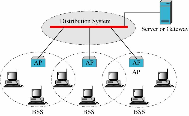
66 ESS illustration 66
67 Distributed Coordination Function (DFC) Basic access method (contention method) Every station, including APs, is required to implement DCF Ad-hoc networks: the only access method Infrastructure networks Obligatory DCF Optional PCF 67
68 Hand shaking Refers to the exchange of two control frames before actual frames are sent Station A sends a request-to-send (RTS) frame to station B The message: duration of actual data exchange B responds with a clear-to-send (CTS) frame The message: duration of actual data exchange, copied from RTS Upon receiving CTS, A sends its frame Upon receiving A s frame B sends ACK frame 68
69 Importance of hand shaking A station hearing RTS refrains from sending until a CTS is sent back to A If a station hears RTS and not CTS => it s not too close to B and can transmit its own data Any station hearing the CTS refrains from sending for the duration indicated in CTS plus some time for ACK to be sent 69
 B responding with a CTS to A.")
70 Hand shaking illustration (a) A sending an RTS to B. (b) B responding with a CTS to A.
71 Collisions If several stations send RTS at the same time => collisions No collision detection mechanism Sender assumes collision if no CTS returns Timer set to wait for CTS Exponential backoff algorithm is used for trying again 71
72 NAV Stands for network allocation vector The stations hearing an RTS/CTS set up the NAV timer Shows how much time should pass before these stations may check the channel for idleness Hence: each station, before sensing the medium, has to have an expired NAV 72
73 NAV illustration 73
74 Fragmentation Wireless networks are noisy and unreliable Probability of success decreases with frame length Fragmentation is then used A fragmentation-threshold parameter defined If frame length exceeds that, frame is fragmented Fragments have own checksum, individually numbered and acknowledged (stop-and-wait) 74
75 Fragments illustration 75
76 More on fragments Fragmentation increases throughput Transmission of only the bad fragments, not entire frame Fragment size Not fixed by standard Parameter of the cell, adjusted by base station NAV mechanism keeps stations quiet until 1 st ACK received Another mechanism used to allow the whole burst sent without interference 76
77 Flow and error control Present also in MAC (not only at LLC level) ACK sent by receivers No NAK When frame is corrupted, silently discarded by receiver Sender has timer to resend frame if ACK not received until timer expires Timer also used for lost frame/ack To prevent duplication, frames have sequence and acknowledgement numbers In data and management frames 77
78 Inter-frame spaces (IFS) To control access to medium 2 IFSs defined Short IFS (SIFS): high priority frames (CTS, ACK, next fragment of a burst) DCF IFS (DIFS): other situations 78
79 NAV and IFSs
80 Point Coordination Function (PFC) Optional access method, to be implemented in an infrastructure network On top of the DCF Used mostly for time-sensitive transmission Uses a centralized, contention-free polling access method Point coordinator software is installed inside AP This software polls for stations capable of polling These stations send their data to AP, one after another 80
81 More on PCF Before starting a polling cycle, PCF uses the contention method (once) PCF has priority over DCF Implemented with PIFS (PCF IFS): < DIFS If a station wants to use DCF and an AP wants to use PCF, AP has priority To let DCF stations to gain access to medium again (later), a repetition interval is designed 81
82 Repetition interval Starts with a special control frame called beacon Broadcast periodically ( times/sec) When stations hear the beacon, they set up their NAV for the duration of the contention-free period Contains System parameters Clock synchronization Invitations to new stations to sign up for polling Receive data, sending ACK, receive ACK Piggybacking possible At the end of this period, a CF end (contention-free end) frame is sent This allows stations to use the contention method again
83 Repetition interval (example)
Local Networks. Lecture 4 6-Apr-2016
 Local Networks Lecture 4 6-Apr-2016 Roadmap of the Course So far Basic telecom concepts General study of LANs LAN topologies Flow and error control Today we continue the general study of LANs Medium access
Jaringan Komputer. Broadcast Network. Outline. MAC (Medium Access Control) Channel Allocation Problem. Dynamic Channel Allocation
 Channel Allocation Problem. Dynamic Channel Allocation") Broadcast Network Jaringan Komputer Medium Access Control Sublayer 2 network categories: point-to-point connections broadcast channels Key issue in broadcast network: how to determine who gets to use the
Broadcast Network Jaringan Komputer Medium Access Control Sublayer 2 network categories: point-to-point connections broadcast channels Key issue in broadcast network: how to determine who gets to use the
Unit 7 Media Access Control (MAC)
") Unit 7 Media Access Control (MAC) 1 Internet Model 2 Sublayers of Data Link Layer Logical link control (LLC) Flow control Error control Media access control (MAC) access control 3 Categorization of MAC
Unit 7 Media Access Control (MAC) 1 Internet Model 2 Sublayers of Data Link Layer Logical link control (LLC) Flow control Error control Media access control (MAC) access control 3 Categorization of MAC
ECEN 5032 Data Networks Medium Access Control Sublayer
 ECEN 5032 Data Networks Medium Access Control Sublayer Peter Mathys mathys@colorado.edu University of Colorado, Boulder c 1996 2005, P. Mathys p.1/35 Overview (Sub)networks can be divided into two categories:
Data and Computer Communications. Chapter 13 Wireless LANs
 Data and Computer Communications Chapter 13 Wireless LANs Wireless LAN Topology Infrastructure LAN Connect to stations on wired LAN and in other cells May do automatic handoff Ad hoc LAN No hub Peer-to-peer
Chapter 12 Multiple Access 12.1
 Chapter 12 Multiple Access 12.1 Copyright The McGraw-Hill Companies, Inc. Permission required for reproduction or display. 12.2 Figure 12.1 Data link layer divided into two functionality-oriented sublayers
Chapter 4. The Medium Access Control Sublayer. Points and Questions to Consider. Multiple Access Protocols. The Channel Allocation Problem.
 Dynamic Channel Allocation in LANs and MANs Chapter 4 The Medium Access Control Sublayer 1. Station Model. 2. Single Channel Assumption. 3. Collision Assumption. 4. (a) Continuous Time. (b) Slotted Time.
Multiple Access Links and Protocols
 Multiple Access Links and Protocols Two types of links : point-to-point PPP for dial-up access point-to-point link between Ethernet switch and host broadcast (shared wire or medium) old-fashioned Ethernet
CHAPTER 7 MAC LAYER PROTOCOLS. Dr. Bhargavi Goswami Associate Professor & Head Department of Computer Science Garden City College
 CHAPTER 7 MAC LAYER PROTOCOLS Dr. Bhargavi Goswami Associate Professor & Head Department of Computer Science Garden City College MEDIUM ACCESS CONTROL - MAC PROTOCOLS When the two stations transmit data
CSCD 433 Network Programming Fall Lecture 7 Ethernet and Wireless
 CSCD 433 Network Programming Fall 2016 Lecture 7 Ethernet and Wireless 802.11 1 Topics 802 Standard MAC and LLC Sublayers Review of MAC in Ethernet MAC in 802.11 Wireless 2 IEEE Standards In 1985, Computer
ECE453 Introduction to Computer Networks. Broadcast vs. PPP. Delay. Lecture 7 Multiple Access Control (I)
") ECE453 Introduction to Computer Networks Lecture 7 Multiple Access Control (I) 1 Broadcast vs. PPP Broadcast channel = multiaccess channel = random access channel Broadcast LAN Satellite network PPP WAN
ECE453 Introduction to Computer Networks Lecture 7 Multiple Access Control (I) 1 Broadcast vs. PPP Broadcast channel = multiaccess channel = random access channel Broadcast LAN Satellite network PPP WAN
Multiple Access. Data Communications and Networking
 Multiple Access In the previous part we discussed data link control, a mechanism which provides a link with reliable communication. In the protocols we described, we assumed that there is an available
Lecture 16: QoS and "
 Lecture 16: QoS and 802.11" CSE 123: Computer Networks Alex C. Snoeren HW 4 due now! Lecture 16 Overview" Network-wide QoS IntServ DifServ 802.11 Wireless CSMA/CA Hidden Terminals RTS/CTS CSE 123 Lecture
Multiple Access Protocols
 Multiple Access Protocols Computer Networks Lecture 2 http://goo.gl/pze5o8 Multiple Access to a Shared Channel The medium (or its sub-channel) may be shared by multiple stations (dynamic allocation) just
Computer Communication III
 Computer Communication III Wireless Media Access IEEE 802.11 Wireless LAN Advantages of Wireless LANs Using the license free ISM band at 2.4 GHz no complicated or expensive licenses necessary very cost
CSE 461: Wireless Networks
 CSE 461: Wireless Networks Wireless IEEE 802.11 A physical and multiple access layer standard for wireless local area networks (WLAN) Ad Hoc Network: no servers or access points Infrastructure Network
CMPE 257: Wireless and Mobile Networking
 CMPE 257: Wireless and Mobile Networking Katia Obraczka Computer Engineering UCSC Baskin Engineering Lecture 3 CMPE 257 Winter'11 1 Announcements Accessing secure part of the class Web page: User id: cmpe257.
Outline. CS5984 Mobile Computing. IEEE 802 Architecture 1/7. IEEE 802 Architecture 2/7. IEEE 802 Architecture 3/7. Dr. Ayman Abdel-Hamid, CS5984
 CS5984 Mobile Computing Dr. Ayman Abdel-Hamid Computer Science Department Virginia Tech Outline IEEE 82 Architecture IEEE 82. Wireless LANs Based on Chapter 4 in Wireless Communications and Networks, William
Wireless Communications
 4. Medium Access Control Sublayer DIN/CTC/UEM 2018 Why do we need MAC for? Medium Access Control (MAC) Shared medium instead of point-to-point link MAC sublayer controls access to shared medium Examples:
Lesson 2-3: The IEEE x MAC Layer
 Module 2: Establishing Wireless Connectivity Lesson 2-3: The IEEE 802.11x MAC Layer Lesson Overview This lesson describes basic IEEE 802.11x MAC operation, beginning with an explanation of contention schemes
04/11/2011. Wireless LANs. CSE 3213 Fall November Overview
 Wireless LANs CSE 3213 Fall 2011 4 November 2011 Overview 2 1 Infrastructure Wireless LAN 3 Applications of Wireless LANs Key application areas: LAN extension cross-building interconnect nomadic access
Chapter 4 (Week 7) The Medium Access Control Sublayer ANDREW S. TANENBAUM COMPUTER NETWORKS FOURTH EDITION PP CN&DC Dr.
 The Medium Access Control Sublayer ANDREW S. TANENBAUM COMPUTER NETWORKS FOURTH EDITION PP CN&DC Dr.") Chapter 4 (Week 7) The Medium Access Control Sublayer ANDREW S. TANENBAUM COMPUTER NETWORKS FOURTH EDITION PP. 247-292 1 4.1. THE CHANNEL ALLOCATION PROBLEM 4.2. MULTIPLE ACCESS PROTOCOLS 4.3. ETHERNET
Chapter 4 (Week 7) The Medium Access Control Sublayer ANDREW S. TANENBAUM COMPUTER NETWORKS FOURTH EDITION PP. 247-292 1 4.1. THE CHANNEL ALLOCATION PROBLEM 4.2. MULTIPLE ACCESS PROTOCOLS 4.3. ETHERNET
Mohamed Khedr.
 Mohamed Khedr http://webmail.aast.edu/~khedr Tentatively Week 1 Week 2 Week 3 Week 4 Week 5 Week 6 Week 7 Week 8 Week 9 Week 10 Week 11 Week 12 Week 13 Week 14 Week 15 Overview Packet Switching IP addressing
The Medium Access Control Scheme (MAC Layer) Reference: Andrew S. Tanenbaum, Computer Networks, 3rd Edition, Prentice Hall, 1996.
 Reference: Andrew S. Tanenbaum, Computer Networks, 3rd Edition, Prentice Hall, 1996.") The Medium Access Control Scheme (MAC Layer) Reference: Andrew S. Tanenbaum, Computer Networks, 3rd Edition, Prentice Hall, 1996. 1 Table of Contents Introduction ALOHA Carrier Sense Multiple Sense (CSMA)
The Medium Access Control Scheme (MAC Layer) Reference: Andrew S. Tanenbaum, Computer Networks, 3rd Edition, Prentice Hall, 1996. 1 Table of Contents Introduction ALOHA Carrier Sense Multiple Sense (CSMA)
IEEE , Token Rings. 10/11/06 CS/ECE UIUC, Fall
 IEEE 802.11, Token Rings 10/11/06 CS/ECE 438 - UIUC, Fall 2006 1 Medium Access Control Wireless channel is a shared medium Need access control mechanism to avoid interference Why not CSMA/CD? 10/11/06
Chapter 6 Medium Access Control Protocols and Local Area Networks
 Chapter 6 Medium Access Control Protocols and Local Area Networks 802.11 Wireless LAN CSE 3213, Winter 2010 Instructor: Foroohar Foroozan Wireless Data Communications Wireless communications compelling
Data Communications. Data Link Layer Protocols Wireless LANs
 Data Communications Data Link Layer Protocols Wireless LANs Wireless Networks Several different types of communications networks are using unguided media. These networks are generally referred to as wireless
2.1 CHANNEL ALLOCATION 2.2 MULTIPLE ACCESS PROTOCOLS Collision Free Protocols 2.3 FDDI 2.4 DATA LINK LAYER DESIGN ISSUES 2.5 FRAMING & STUFFING
 UNIT-2 2.1 CHANNEL ALLOCATION 2.2 MULTIPLE ACCESS PROTOCOLS 2.2.1 Pure ALOHA 2.2.2 Slotted ALOHA 2.2.3 Carrier Sense Multiple Access 2.2.4 CSMA with Collision Detection 2.2.5 Collision Free Protocols 2.2.5.1
Solutions to Exercise Session 4,
 Solutions to Exercise Session 4, 27.4.2012 I.1. Chapter 14: 2, 4, 5, 7, 8, 21, 23, 24-26 2. a 4. b, c 5. c 7. b 8. a 21. a 23. a 24. 25. 26. Token bus networks are intended for factory automation; hence
4.3 IEEE Physical Layer IEEE IEEE b IEEE a IEEE g IEEE n IEEE 802.
 4.3 IEEE 802.11 Physical Layer 4.3.1 IEEE 802.11 4.3.2 IEEE 802.11b 4.3.3 IEEE 802.11a 4.3.4 IEEE 802.11g 4.3.5 IEEE 802.11n 4.3.6 IEEE 802.11ac,ad Andreas Könsgen Summer Term 2012 4.3.3 IEEE 802.11a Data
CMPE 257: Wireless and Mobile Networking
 CMPE 257: Wireless and Mobile Networking Katia Obraczka Computer Engineering UCSC Baskin Engineering Lecture 3 CMPE 257 Spring'15 1 Next week Announcements April 14: ICN (Spencer Sevilla) April 16: DTN
Medium Access Control. IEEE , Token Rings. CSMA/CD in WLANs? Ethernet MAC Algorithm. MACA Solution for Hidden Terminal Problem
 Medium Access Control IEEE 802.11, Token Rings Wireless channel is a shared medium Need access control mechanism to avoid interference Why not CSMA/CD? 9/15/06 CS/ECE 438 - UIUC, Fall 2006 1 9/15/06 CS/ECE
CS 43: Computer Networks. 27: Media Access Contd. December 3, 2018
 CS 43: Computer Networks 27: Media Access Contd. December 3, 2018 Last Class The link layer provides lots of functionality: addressing, framing, media access, error checking could be used independently
Local Area Networks NETW 901
 Local Area Networks NETW 901 Lecture 4 Wireless LAN Course Instructor: Dr.-Ing. Maggie Mashaly maggie.ezzat@guc.edu.eg C3.220 1 Contents What is a Wireless LAN? Applications and Requirements Transmission
MAC in /20/06
 MAC in 802.11 2/20/06 MAC Multiple users share common medium. Important issues: Collision detection Delay Fairness Hidden terminals Synchronization Power management Roaming Use 802.11 as an example to
Wireless LANs. ITS 413 Internet Technologies and Applications
 Wireless LANs ITS 413 Internet Technologies and Applications Aim: Aim and Contents Understand how IEEE 802.11 wireless LANs work Understand what influences the performance of wireless LANs Contents: IEEE
ICE 1332/0715 Mobile Computing (Summer, 2008)
") ICE 1332/0715 Mobile Computing (Summer, 2008) Medium Access Control Prof. Chansu Yu http://academic.csuohio.edu/yuc/ Simplified Reference Model Application layer Transport layer Network layer Data link
ICE 1332/0715 Mobile Computing (Summer, 2008) Medium Access Control Prof. Chansu Yu http://academic.csuohio.edu/yuc/ Simplified Reference Model Application layer Transport layer Network layer Data link
Logical Link Control (LLC) Medium Access Control (MAC)
 Medium Access Control (MAC)") Overview of IEEE 802.11 Data Link layer Application Presentation Session Transport LLC: On transmission, assemble data into a frame with address and CRC fields. On reception, disassemble frame, perform
Overview of IEEE 802.11 Data Link layer Application Presentation Session Transport LLC: On transmission, assemble data into a frame with address and CRC fields. On reception, disassemble frame, perform
MAC. Fall Data Communications II 1
 802.11 MAC Fall 2005 91.564 Data Communications II 1 RF Quality (ACK) Fall 2005 91.564 Data Communications II 2 Hidden Terminal (RTS/CTS) Fall 2005 91.564 Data Communications II 3 MAC Coordination Functions
The MAC layer in wireless networks
 The MAC layer in wireless networks The wireless MAC layer roles Access control to shared channel(s) Natural broadcast of wireless transmission Collision of signal: a /space problem Who transmits when?
LANs. Local Area Networks. via the Media Access Control (MAC) SubLayer. Networks: Local Area Networks
 SubLayer. Networks: Local Area Networks") LANs Local Area Networks via the Media Access Control (MAC) SubLayer 1 Local Area Networks Aloha Slotted Aloha CSMA (non-persistent, 1-persistent, p-persistent) CSMA/CD Ethernet Token Ring 2 Network Layer
LANs Local Area Networks via the Media Access Control (MAC) SubLayer 1 Local Area Networks Aloha Slotted Aloha CSMA (non-persistent, 1-persistent, p-persistent) CSMA/CD Ethernet Token Ring 2 Network Layer
IEEE Medium Access Control. Medium Access Control
 IEEE 802.11 Medium Access Control EECS3214 3 April 2018 Medium Access Control reliable data delivery access control MAC layer covers three functional areas: security 2 1 MAC Requirements To avoid interference
Topics for Today. More on Ethernet. Wireless LANs Readings. Topology and Wiring Switched Ethernet Fast Ethernet Gigabit Ethernet. 4.3 to 4.
 Topics for Today More on Ethernet Topology and Wiring Switched Ethernet Fast Ethernet Gigabit Ethernet Wireless LANs Readings 4.3 to 4.4 1 Original Ethernet Wiring Heavy coaxial cable, called thicknet,
Link Layer: Retransmissions
 Link Layer: Retransmissions Context on Reliability Where in the stack should we place reliability functions? Application Transport Network Link Physical CSE 461 University of Washington 2 Context on Reliability
Chapter 5 Data-Link Layer: Wired Networks
 Sungkyunkwan University Chapter 5 Data-Link Layer: Wired Networks Prepared by Syed M. Raza and H. Choo 2018-Fall Computer Networks Copyright 2000-2018 Networking Laboratory Chapter 5 Outline 5.1 Introduction
Medium Access Control Sublayer
 Wireless (WLAN) Medium Access Control Sublayer Mahalingam Mississippi State University, MS October 20, 2014 Outline Medium Access Protocols Wireless (WLAN) 1 Medium Access Protocols ALOHA Slotted ALOHA
MAC Sublayer(1) Principal service of the Medium Access Control Sublayer: Allocating a single broadcast channel (mostly a LAN) among competing users
 Principal service of the Medium Access Control Sublayer: Allocating a single broadcast channel (mostly a LAN) among competing users") MAC Sublayer(1) Principal service of the Medium Access Control Sublayer: Allocating a single broadcast channel (mostly a LAN) among competing users Static Channel Allocation: Frequency Division Multiplexing
MAC Sublayer(1) Principal service of the Medium Access Control Sublayer: Allocating a single broadcast channel (mostly a LAN) among competing users Static Channel Allocation: Frequency Division Multiplexing
MSIT 413: Wireless Technologies Week 8
 MSIT 413: Wireless Technologies Week 8 Michael L. Honig Department of EECS Northwestern University November 2017 The Multiple Access Problem How can multiple mobiles access (communicate with) the same
CS 43: Computer Networks Media Access. Kevin Webb Swarthmore College November 30, 2017
 CS 43: Computer Networks Media Access Kevin Webb Swarthmore College November 30, 2017 Multiple Access Links & Protocols Two classes of links : point-to-point dial-up access link between Ethernet switch,
Wireless Local Area Networks. Networks: Wireless LANs 1
 Wireless Local Area Networks Networks: Wireless LANs 1 Wireless Local Area Networks The proliferation of laptop computers and other mobile devices (PDAs and cell phones) created an obvious application
Mobile Communications Chapter 7: Wireless LANs
 Characteristics IEEE 802.11 PHY MAC Roaming IEEE 802.11a, b, g, e HIPERLAN Bluetooth Comparisons Prof. Dr.-Ing. Jochen Schiller, http://www.jochenschiller.de/ MC SS02 7.1 Comparison: infrastructure vs.
Chapter 4. The Medium Access Control Sublayer
 Chapter 4 The Medium Access Control Sublayer The Channel Allocation Problem Static Channel Allocation in LANs and MANs Dynamic Channel Allocation in LANs and MANs Dynamic Channel Allocation in LANs and
CSE 6811 Ashikur Rahman
 Data Link layer Application Overview of IEEE 802.11 LLC: On transmission, assemble data into a frame with address and CRC fields. On reception, disassemble frame, perform address recognition and CRC validation.
Wireless Local Area Networks (WLANs)) and Wireless Sensor Networks (WSNs) Computer Networks: Wireless Networks 1
) and Wireless Sensor Networks (WSNs) Computer Networks: Wireless Networks 1") Wireless Local Area Networks (WLANs)) and Wireless Sensor Networks (WSNs) Computer Networks: Wireless Networks 1 Wireless Local Area Networks The proliferation of laptop computers and other mobile devices
Wireless Local Area Networks (WLANs)) and Wireless Sensor Networks (WSNs) Computer Networks: Wireless Networks 1 Wireless Local Area Networks The proliferation of laptop computers and other mobile devices
Rahman 1. Application
 Data Link layer Overview of IEEE 802.11 Application Presentation Session Transport LLC: On transmission, assemble data into a frame with address and CRC fields. On reception, disassemble frame, perform
Advanced Computer Networks. Rab Nawaz Jadoon DCS. Assistant Professor COMSATS University, Lahore Pakistan. Department of Computer Science
 Advanced Computer Networks Rab Nawaz Jadoon Department of Computer Science DCS COMSATS Institute of Information Technology Assistant Professor COMSATS University, Lahore Pakistan Advanced Computer Networks
Redes de Computadores. Medium Access Control
 Redes de Computadores Medium Access Control Manuel P. Ricardo Faculdade de Engenharia da Universidade do Porto 1 » How to control the access of computers to a communication medium?» What is the ideal Medium
CSE 461: Multiple Access Networks. This Lecture
 CSE 461: Multiple Access Networks This Lecture Key Focus: How do multiple parties share a wire? This is the Medium Access Control (MAC) portion of the Link Layer Randomized access protocols: 1. Aloha 2.
Flow control: Ensuring the source sending frames does not overflow the receiver
 Layer 2 Technologies Layer 2: final level of encapsulation of data before transmission over a physical link responsible for reliable transfer of frames between hosts, hop by hop, i.e. on a per link basis
High Level View. EE 122: Ethernet and Random Access protocols. Medium Access Protocols
 High Level View EE 122: Ethernet and 802.11 Ion Stoica September 18, 2002 Goal: share a communication medium among multiple hosts connected to it Problem: arbitrate between connected hosts Solution goals:
Aloha and slotted aloha
 CSMA 2/13/06 Aloha and slotted aloha Slotted aloha: transmissions are synchronized and only start at the beginning of a time slot. Aloha sender A sender B collision sender C t Slotted Aloha collision sender
The MAC layer in wireless networks
 The MAC layer in wireless networks The wireless MAC layer roles Access control to shared channel(s) Natural broadcast of wireless transmission Collision of signal: a time/space problem Who transmits when?
Data Link Layer: Collisions
 Data Link Layer: Collisions 1 Multiple Access Data Link layer divided into two sublayers. The upper sublayer is responsible for datalink control, The lower sublayer is responsible for resolving access
Topics. Link Layer Services (more) Link Layer Services LECTURE 5 MULTIPLE ACCESS AND LOCAL AREA NETWORKS. flow control: error detection:
 Link Layer Services LECTURE 5 MULTIPLE ACCESS AND LOCAL AREA NETWORKS. flow control: error detection:") 1 Topics 2 LECTURE 5 MULTIPLE ACCESS AND LOCAL AREA NETWORKS Multiple access: CSMA/CD, CSMA/CA, token passing, channelization LAN: characteristics, i basic principles i Protocol architecture Topologies
1 Topics 2 LECTURE 5 MULTIPLE ACCESS AND LOCAL AREA NETWORKS Multiple access: CSMA/CD, CSMA/CA, token passing, channelization LAN: characteristics, i basic principles i Protocol architecture Topologies
COMPUTER NETWORKS UNIT 3
 COMPUTER NETWORKS UNIT 3 1. Illustrate about Reservation, Polling and Token Passing. [10 marks] Controlled access: In controlled access, the stations consult one another to find which station has the right
COS 140: Foundations of Computer Science
 COS 140: Foundations of Computer Science ALOHA Network Protocol Family Fall 2017 Homework 2 Introduction 3 Network Protocols.......................................................... 3 Problem.................................................................
Lecture 4: Wireless MAC Overview. Hung-Yu Wei National Taiwan University
 Lecture 4: Wireless MAC Overview Hung-Yu Wei National Taiwan University Medium Access Control Topology 3 Simplex and Duplex 4 FDMA TDMA CDMA DSSS FHSS Multiple Access Methods Notice: CDMA and spread spectrum
Intelligent Transportation Systems. Medium Access Control. Prof. Dr. Thomas Strang
 Intelligent Transportation Systems Medium Access Control Prof. Dr. Thomas Strang Recap: Wireless Interconnections Networking types + Scalability + Range Delay Individuality Broadcast o Scalability o Range
Introduction to Wireless Networking CS 490WN/ECE 401WN Winter Lecture 4: Wireless LANs and IEEE Part II
 Introduction to Wireless Networking CS 490WN/ECE 401WN Winter 2007 Lecture 4: Wireless LANs and IEEE 802.11 Part II This lecture continues the study of wireless LANs by looking at IEEE 802.11. I. 802.11
CS 348: Computer Networks. - WiFi (contd.); 16 th Aug Instructor: Sridhar Iyer IIT Bombay
; 16 th Aug Instructor: Sridhar Iyer IIT Bombay") CS 348: Computer Networks - WiFi (contd.); 16 th Aug 2012 Instructor: Sridhar Iyer IIT Bombay Clicker-1: Wireless v/s wired Which of the following differences between Wireless and Wired affect a CSMA-based
CS 348: Computer Networks - WiFi (contd.); 16 th Aug 2012 Instructor: Sridhar Iyer IIT Bombay Clicker-1: Wireless v/s wired Which of the following differences between Wireless and Wired affect a CSMA-based
EE 122: Ethernet and
 EE 122: Ethernet and 802.11 Ion Stoica September 18, 2002 (* this talk is based in part on the on-line slides of J. Kurose & K. Rose) High Level View Goal: share a communication medium among multiple hosts
Announcements / Wireless Networks and Applications Lecture 9: Wireless LANs Wireless. Regular Ethernet CSMA/CD.
 Announcements 18-452/18-750 Wireless Networks and Applications Lecture 9: Wireless LANs 802.11 Wireless Peter Steenkiste Homework 1 should be out by tomorrow Project 1 by Friday Schedule:» Thursday lecture
Getting Connected (Chapter 2 Part 4) Networking CS 3470, Section 1 Sarah Diesburg
 Networking CS 3470, Section 1 Sarah Diesburg") Getting Connected (Chapter 2 Part 4) Networking CS 3470, Section 1 Sarah Diesburg Five Problems Encoding/decoding Framing Error Detection Error Correction Media Access Five Problems Encoding/decoding Framing
Getting Connected (Chapter 2 Part 4) Networking CS 3470, Section 1 Sarah Diesburg Five Problems Encoding/decoding Framing Error Detection Error Correction Media Access Five Problems Encoding/decoding Framing
Computer Network Fundamentals Spring Week 3 MAC Layer Andreas Terzis
 Computer Network Fundamentals Spring 2008 Week 3 MAC Layer Andreas Terzis Outline MAC Protocols MAC Protocol Examples Channel Partitioning TDMA/FDMA Token Ring Random Access Protocols Aloha and Slotted
Lecture (08) Wireless Traffic Flow and AP Discovery
 Wireless Traffic Flow and AP Discovery") Lecture (08) Wireless Traffic Flow and AP Discovery Dr. Ahmed ElShafee 1 Dr. Ahmed ElShafee, ACU Spring 2011, Wireless Network Agenda Wireless Frame Types Sending a Frames Wireless Frame Headers Frame
Lecture (08) Wireless Traffic Flow and AP Discovery Dr. Ahmed ElShafee 1 Dr. Ahmed ElShafee, ACU Spring 2011, Wireless Network Agenda Wireless Frame Types Sending a Frames Wireless Frame Headers Frame
Department of Electrical and Computer Systems Engineering
 Department of Electrical and Computer Systems Engineering Technical Report MECSE-6-2006 Medium Access Control (MAC) Schemes for Quality of Service (QoS) provision of Voice over Internet Protocol (VoIP)
Chapter 4: The Medium Access Layer
 Chapter 4: The Medium Access Layer Computer Networks Maccabe Computer Science Department The University of New Mexico September 2002 Medium Access Layer Point-to-point versus broadcast networks Broadcast
Random Assignment Protocols
 Random Assignment Protocols Random assignment strategies attempt to reduce problem occur in fixed assignment strategy by eliminating pre allocation of bandwidth to communicating nodes. Random assignment
LECTURE PLAN. Script. Introduction about MAC Types o ALOHA o CSMA o CSMA/CD o CSMA/CA
 Course- B.Sc. Applied Physical Science (Computer Science) Year- IIIrd, Sem- Vth Subject Computer Science Paper- XVIIth, Computer Networks Lecture -11 Lecture Title- Medium Access Layer Script Today in
CHAPTER 8: LAN Standards
 CHAPTER 8: LAN Standards DR. BHARGAVI GOSWAMI, ASSOCIATE PROFESSOR HEAD, DEPARTMENT OF COMPUTER SCIENCE, GARDEN CITY COLLEGE BANGALORE. LAN STRUCTURE NETWORK INTERFACE CARD MEDIUM ACCESS CONTROL SUB LAYER
CS 716: Introduction to communication networks. - 9 th class; 19 th Aug Instructor: Sridhar Iyer IIT Bombay
 CS 716: Introduction to communication networks - 9 th class; 19 th Aug 2011 Instructor: Sridhar Iyer IIT Bombay Contention-based MAC: ALOHA Users transmit whenever they have data to send Collisions occur,
Media Access Control in Ad Hoc Networks
 Media Access Control in Ad Hoc Networks The Wireless Medium is a scarce precious resource. Furthermore, the access medium is broadcast in nature. It is necessary to share this resource efficiently and
ICE 1332/0715 Mobile Computing (Summer, 2008)
") ICE 1332/0715 Mobile Computing (Summer, 2008) IEEE 802.11 Prof. Chansu Yu http://academic.csuohio.edu/yuc/ Contents Overview of IEEE 802.11 Frame formats MAC frame PHY frame IEEE 802.11 IEEE 802.11b IEEE
ICE 1332/0715 Mobile Computing (Summer, 2008) IEEE 802.11 Prof. Chansu Yu http://academic.csuohio.edu/yuc/ Contents Overview of IEEE 802.11 Frame formats MAC frame PHY frame IEEE 802.11 IEEE 802.11b IEEE
Computer Networks. Medium Access Sublayer (Part I)
") Computer Networks Medium Access Sublayer (Part I) Topics Introduction Multiple Access Protocols Ethernet Wireless LAN Protocols Bridges Misc (brief) High-Speed LANs Satellite Networks Introduction Remember,
Computer Networks Medium Access Sublayer (Part I) Topics Introduction Multiple Access Protocols Ethernet Wireless LAN Protocols Bridges Misc (brief) High-Speed LANs Satellite Networks Introduction Remember,
CS 123: Lecture 12, LANs, and Ethernet. George Varghese. October 24, 2006
 CS 123: Lecture 12, LANs, and Ethernet George Varghese October 24, 2006 Selective Reject Modulus failure Example w = 2, Max = 3 0 0 1 3 0 A(1) A(2) 1 0 retransmit A(1) A(2) buffer Case 1 Case 2 reject
Medium Access Control. MAC protocols: design goals, challenges, contention-based and contention-free protocols
 Medium Access Control MAC protocols: design goals, challenges, contention-based and contention-free protocols 1 Why do we need MAC protocols? Wireless medium is shared Many nodes may need to access the
Wireless Challenges : Computer Networking. Overview. Routing to Mobile Nodes. Lecture 25: Wireless Networking
 Wireless Challenges 15-441: Computer Networking Lecture 25: Wireless Networking Force us to rethink many assumptions Need to share airwaves rather than wire Don t know what hosts are involved Host may
Wireless LAN -Architecture
 Wireless LAN -Architecture IEEE has defined the specifications for a wireless LAN, called IEEE 802.11, which covers the physical and data link layers. Basic Service Set (BSS) Access Point (AP) Distribution
Wireless Protocols. Training materials for wireless trainers
 Wireless Protocols Training materials for wireless trainers Goals The goal of this lecture is to introduce: IEEE wireless protocols coverage 802.11 radio protocols terminology WiFi modes of operation details
IEEE MAC Sublayer (Based on IEEE )
") IEEE 802.11 MAC Sublayer (Based on IEEE 802.11-1999) Wireless Networking Sunghyun Choi, Associate Professor Multimedia & Wireless Networking Lab. (MWNL) School of Electrical Engineering Seoul National
IEEE 802.11 MAC Sublayer (Based on IEEE 802.11-1999) Wireless Networking Sunghyun Choi, Associate Professor Multimedia & Wireless Networking Lab. (MWNL) School of Electrical Engineering Seoul National
Chapter 6 Wireless and Mobile Networks. Csci 4211 David H.C. Du
 Chapter 6 Wireless and Mobile Networks Csci 4211 David H.C. Du Wireless LAN IEEE 802.11 a, b, g IEEE 802.15 Buletooth Hidden Terminal Effect Hidden Terminal Problem Hidden terminals A, C cannot hear each
Wireless Medium Access Control Protocols
 Wireless Medium Access Control Protocols Telecomunicazioni Undergraduate course in Electrical Engineering University of Rome La Sapienza Rome, Italy 2007-2008 Classification of wireless MAC protocols Wireless
COS 140: Foundations of Computer Science
 COS 140: Foundations of C S Network Protocol Family Fall 2017 Copyright c 2002 2017 UMaine School of Computing and Information S 1 / 25 Homework Homework Slides, book Chapter 24 on line Homework: All exercises
Lecture 6. Data Link Layer (cont d) Data Link Layer 1-1
 Data Link Layer 1-1") Lecture 6 Data Link Layer (cont d) Data Link Layer 1-1 Agenda Continue the Data Link Layer Multiple Access Links and Protocols Addressing Data Link Layer 1-2 Multiple Access Links and Protocols Two types
Lecture 6 Data Link Layer (cont d) Data Link Layer 1-1 Agenda Continue the Data Link Layer Multiple Access Links and Protocols Addressing Data Link Layer 1-2 Multiple Access Links and Protocols Two types
standard. Acknowledgement: Slides borrowed from Richard Y. Yale
 802.11 standard Acknowledgement: Slides borrowed from Richard Y. Yang @ Yale IEEE 802.11 Requirements Design for small coverage (e.g. office, home) Low/no mobility High data rate applications Ability to
Lecture 25: CSE 123: Computer Networks Alex C. Snoeren. HW4 due NOW
 Lecture 25: 802.11 CSE 123: Computer Networks Alex C. Snoeren HW4 due NOW Lecture 25 Overview 802.11 Wireless PHY layer overview Hidden Terminals Basic wireless challenge RTS/CTS Virtual carrier sense
Wireless Communication and Networking CMPT 371
 Wireless Communication and Networking CMPT 371 Wireless Systems: AM, FM Radio TV Broadcast Satellite Broadcast 2-way Radios Cordless Phones Satellite Links Mobile Telephony Systems Wireless Local Loop
Wireless Local Area Networks (WLANs) Part I
 Part I") Wireless Local Area Networks (WLANs) Part I Raj Jain Professor of CSE Washington University in Saint Louis Saint Louis, MO 63130 Jain@cse.wustl.edu These slides are available on-line at: http://www.cse.wustl.edu/~jain/cse574-08/
Wireless Local Area Networks (WLANs) Part I Raj Jain Professor of CSE Washington University in Saint Louis Saint Louis, MO 63130 Jain@cse.wustl.edu These slides are available on-line at: http://www.cse.wustl.edu/~jain/cse574-08/
Links Reading: Chapter 2. Goals of Todayʼs Lecture. Message, Segment, Packet, and Frame
 Links Reading: Chapter 2 CS 375: Computer Networks Thomas Bressoud 1 Goals of Todayʼs Lecture Link-layer services Encoding, framing, and error detection Error correction and flow control Sharing a shared
Link Layer and Ethernet
 Link Layer and Ethernet 14-740: Fundamentals of Computer Networks Bill Nace Material from Computer Networking: A Top Down Approach, 6 th edition. J.F. Kurose and K.W. Ross traceroute Data Link Layer Multiple