Housekeeping. Cisco Public BRKCRS Cisco and/or its affiliates. All rights reserved.
|
|
|
- Susan Briggs
- 5 years ago
- Views:
Transcription
1
2 Housekeeping We value your feedback- don't forget to complete your online session evaluations after each session & complete the Overall Conference Evaluation which will be available online from Thursday Visit the World of Solutions Please remember this is a 'non-smoking' venue! Please switch off your mobile phones Please make use of the recycling bins provided Please remember to wear your badge at all times 2
3 Presentation Legend Key Points Reference Material Standalone Multilayer Switch Virtual Switching System Layer 2 Link Layer 3 Link 3
4 VSS Introduction
, L2")
5 Current Network Challenges Traditional Enterprise Campus Multi-layer Design L3 Core Extensive routing topology, Routing reconvergence L2/L3 Distribution FHRP, STP, Asymmetric routing, Policy Management Access Single active uplink per VLAN (PVST), L2 reconvergence 5

, L2 reconvergence L2")
6 Current Network Challenges Traditional Data Center Multi-layer Design FHRP, HSRP, VRRP Spanning Tree Policy Management L2/L3 Core Single active uplink per VLAN (PVST), L2 reconvergence, excessive BPDUs Dual-Homed Servers to single switch, Single active uplink per VLAN (PVST), L2 reconvergence L2 Access 6
7 Virtual Switching System Traditional Design VSS Design 7


8 Virtual Switching System VSS Enterprise Campus L3 Core Reduced routing neighbors, Minimal L3 reconvergence L2/L3 Distribution No FHRPs No Looped topology Policy Management Access Multiple active uplinks per VLAN, No STP convergence 8
9 VSS Simplifies the Configuration Standalone Switch 1 (Coordinated Configuration) Si Standalone Switch 2 (Coordinated Configuration) Si VSS (One simplified configuration) Spanning Tree Configuration! Enable 802.1d per VLAN spanning tree enhancements. spanning-tree mode pvst spanning-tree loopguard default no spanning-tree optimize bpdu transmission spanning-tree extend system-id spanning-tree uplinkfast spanning-tree backbonefast spanning-tree vlan 2,4,6,8,10 priority 24576!! Enable 802.1d per VLAN spanning tree enhancements. spanning-tree mode pvst spanning-tree loopguard default no spanning-tree optimize bpdu transmission spanning-tree extend system-id spanning-tree uplinkfast spanning-tree backbonefast spanning-tree vlan 3,5,7,9,11 priority 24576!! Enable 802.1d per VLAN spanning tree enhancements spanning-tree mode rapid-pvst no spanning-tree optimize bpdu transmission spanning-tree extend system-id spanning-tree vlan 2-11 priority L3 SVI Configuration (sample for 1 VLAN)! Define the Layer 3 SVI for each voice and data VLAN interface Vlan4 description Data VLAN ip address no ip redirects no ip unreachables! Reduce PIM query interval to 250 msec ip pim query-interval 250 msec ip pim sparse-mode load-interval 30! Define HSRP default gateway with 250/800 msec hello/hold standby 1 ip standby 1 timers msec 250 msec 800! Set preempt delay large enough to allow network to stabilize before HSRP! switches back on power on or link recovery standby 1 preempt delay minimum 180! Enable HSRP authentication standby 1 authentication cisco123! Define the Layer 3 SVI for each voice and data VLAN interface Vlan4 description Data VLAN ip address no ip redirects no ip unreachables! Reduce PIM query interval to 250 msec ip pim query-interval 250 msec ip pim sparse-mode load-interval 30! Define HSRP default gateway with 250/800 msec hello/hold standby 1 ip standby 1 timers msec 250 msec 800! Set preempt delay large enough to allow network to stabilize before HSRP! switches back on power on or link recovery standby 1 preempt delay minimum 180! Enable HSRP authentication standby 1 authentication cisco123! Define the Layer 3 SVI for each voice and data VLAN interface Vlan4 description Data VLAN ip address no ip redirects no ip unreachables ip pim sparse-mode load-interval 30 9


10 Catalyst 6500 Virtual Switching System Benefits Summary Traditional VSS (Physical View) VSS (Logical View) 10GE 10GE Si Si Si Si 802.3ad or PagP 802.3ad 802.3ad or PagP 802.3ad Access Switch or ToR or Blades Server Access Switch or ToR or Blades Server Access Switch or ToR or Blades Server Simplifies operational Manageability via Single point of Management, Non-loop design, minimize reliance on STP, eliminate FHRP etc Scales system capacity with Active-Active Multi-Chassis Etherchannel (802.3ad/PagP), no blocking links due to Spanning Tree Minimizes traffic disruption from switch or uplink failure with Deterministic subsecond Stateful and 2012 Cisco Graceful and/or its affiliates. Recovery All rights reserved. (SSO/NSF) 10
11 VSS Architecture
12 VSS Architecture Concepts Active Virtual Switch Domain Control Plane Standby Hot Virtual Switch Link Switch 1 Switch 2 Active Data Plane Active 12

13 Virtual Switching System Architecture Virtual Switch Link (VSL) Virtual Switch Link Control Link Switch 1 Data Links Switch 2 Virtual Switch Active Port Channel 1 interface Port-channel1 no switchport no ip address switch virtual link 1 mls qos trust cos no mls qos channel-consistency! interface Port-channel2 no switchport no ip address switch virtual link 2 mls qos trust cos no mls qos channel-consistency Port Channel 2 Virtual Switch Standby 13
14 Virtual Switching System Architecture Virtual Switch Link (VSL) Virtual Switch Link Control Link Data Links Switch 1 Port Channel 1 Port Channel 2 Switch 2 Virtual Switch Active Virtual Switch Standby VS Header L2 Hdr L3 Hdr Data CRC All traffic traversing the VSL link is encapsulated with a 32 byte Virtual Switch Header containing ingress and egress switchport indexes, class of service (COS), VLAN number, other important information from the layer 2 and layer 3 header 14
15 Virtual Switching System Dual Active Forwarding Planes Both data and forwarding planes are active Standby supervisor and all line cards are actively forwarding No STP blocking ports due to Etherchannel uplinks Switch 1 Switch 2 VSS# show switch virtual redundancy My Switch Id = 1 Peer Switch Id = 2 <snip> Switch 1 Slot 5 Processor Information : Current Software state = ACTIVE <snip> Fabric State = ACTIVE Control Plane State = ACTIVE Switch 2 Slot 5 Processor Information : Current Software state = STANDBY HOT (switchover target) <snip> Fabric State = ACTIVE Control Plane State = STANDBY Switch 1 Switch 2 15
16 Virtual Switching System Architecture Initialization Virtual Switch Link Port Channel 1 Port Channel 2 Switch 1 Switch Pre-parse config file and bring up VSL interfaces Link Management Protocol (LMP) used to track and reject Unidirectional Links, Exchange Chassis ID and other information between the 2 switches Role Resolution Protocol (RRP) used to determine compatible Hardware and Software versions to form the VSL as well as determine which switch becomes Active and Hot Standby from a control plane perspective 16
17 Virtual Switching System Architecture VSL Configuration Consistency Check After the roles have been resolved through Role Resolution Protocol, a Configuration Consistency Check is performed across the VSL switches to ensure proper VSL operation. The following items are checked for consistency: Virtual Switch Switch Virtual Domain ID Switch Virtual Switch ID Switch Priority Switch Preempt VSL Port Channel Link ID VSL Port state, interfaces Power Redundancy mode Power Enable on VSL cards Note that if configurations do not match, the Hot-Standby Supervisor will revert to Route Processor Redundancy mode, disabling all non-vsl interfaces 17

18 VSS Output show switch virtual 6500-VSS#show switch virtual? dual-active link redundancy role slot-map Virtual switch dual-active information Virtual switch link information vs pseudo-standby status Virtual switch role information virtual slot map table troubleshooting vs vsl troubleshooting output Troubleshooting provides a single command to gather all VSS related troubleshooting data, simplifies gathering data for TAC 18
")
19 VSS Output show switch virtual role CiscoLive-A# show switch virtual role RRP information for Instance Valid Flags Peer Preferred Reserved Count Peer Peer TRUE V Switch Switch Status Preempt Priority Role Local Remote Number Oper(Conf) Oper(Conf) SID SID LOCAL 2 UP FALSE(N ) 100(100) ACTIVE 0 0 REMOTE 1 UP FALSE(N ) 100(100) STANDBY Peer 0 represents the local switch Flags : V - Valid In dual-active recovery mode: No CiscoLive-A# 19

20 VSS Output show switch virtual role redundancy CiscoLive-A# show switch virtual role redundancy My Switch Id = 2 Peer Switch Id = 1 Last switchover reason = active unit removed Configured Redundancy Mode = sso Operating Redundancy Mode = sso Switch 2 Slot 8 Processor Information : Current Software state = ACTIVE Uptime in current state = 1 day, 1 hour, 39 minutes Image Version = Cisco IOS Software, s2t54 Software (s2t54-adventerprisek9_dbg-m), Version 12.2(49)SY131.71, INTERIM SOFTWARE Synced to CARSON_BASE_FOR_V122_50_SY_THROTTLE_121610_101313, Weekly Branch: v122_50_sy_throttle BOOT = bootdisk:s2t54-adventerprisek9_dbg-mz.ssa sy131.71_110421,1; CONFIG_FILE = BOOTLDR = Configuration register = 0x2102 Fabric State = ACTIVE Control Plane State = ACTIVE Switch 1 Slot 6 Processor Information : Current Software state = STANDBY HOT (switchover target) Uptime in current state = 1 day, 1 hour, 35 minutes Image Version = Cisco IOS Software, s2t54 Software (s2t54-adventerprisek9_dbg-m), Version 12.2(49)SY131.71, INTERIM SOFTWARE Synced to CARSON_BASE_FOR_V122_50_SY_THROTTLE_121610_101313, Weekly Branch: v122_50_sy_throttle BOOT = bootdisk:s2t54-adventerprisek9_dbg-mz.ssa sy131.71_110421,1; CONFIG_FILE = BOOTLDR = Configuration register = 0x2102 Fabric State = ACTIVE Control Plane State = STANDBY 20
21 Virtual Switching System Architecture Traffic Forwarding Enhancements For a VSS, Etherchannel and L3 ECMP forwarding will always favor locally attached interfaces Deterministic Traffic patterns Removes the need to send traffic over the VSL Multichassis Etherchannel (MEC) L3 Equal Cost Multi-Path Routing (ECMP) 21


22 Etherchannel Traffic Load Balancing IPSA IPDA MAC L4 Ports 22

23 Virtual Switching System Architecture Multichassis EtherChannel (MEC) Traditional Etherchannel One logical link partner, but two physical chassis Multichassis Etherchannel (MEC) 25
24 Virtual Switching System Architecture EtherChannel Hash for MEC Etherchannel hashing algorithms are modified in VSS to always favor locally attached interfaces Logical Interface Physical Interface PO-1 T 1/1/1 Result Bundle Hash (RBH) Value 0,1,2,3,4,5,6,7 Logical Interface Physical Interface PO-1 T 1/1/1 Result Bundle Hash (RBH) Value PO-1 T2/1/1 PO-1 T2/1/1 0,1,2,3,4,5,6,7 Blue Traffic destined for the Server will result in Link 1 in the MEC link bundle being chosen as the destination path Link 1 Link 2 Orange Traffic destined for the Server will result in Link 2 in the MEC link bundle being chosen as the destination path 26

25 Etherchannel Concepts Etherchannel Hash Distribution Adaptive Adaptive Hash Distribution Enhancement allows for the addition or removal of links in a bundle without affecting all of the traffic in an Etherchannel. Note in the below example, only Flow 7 and 8 are affected by the addition of an extra link to the Channel RBH (for MEC) 2 Link Bundle Example Link 1 Link 2 Flow 1 Flow 2 Flow 3 Flow 4 Flow 5 Flow 6 Flow 7 Flow 8 RBH (for MEC) 3 Link Bundle Example Link 1 Link 2 Link 3 Flow 1 Flow 2 Flow 3 Flow 4 Flow 5 Flow 6 Flow 7 Flow 8 vss# conf t Enter configuration commands, one per line. End with CNTL/Z. vss(config)#port-channel hash-distribution adaptive vss(config)# ^Z vss# Default for VSS in 12.2(33)SXH1, 28
26 How Etherchannel Works Show Commands VSS-Sup720# show etherchannel 1 port-channel Port-channels in the group: Port-channel: Po Age of the Port-channel = 2d:21h:10m:59s Logical slot/port = 46/1 Number of ports = 2 GC = 0x HotStandBy port = null Passive port list = Te1/6/4 Te1/6/5 Port state = Port-channel L3-Ag Ag-Inuse Protocol = - Fast-switchover = disabled Load share deferral = disabled Ports in the Port-channel: Index Load Port EC state No of bits Te1/6/4 On 4 1 6A Te1/6/5 On 4 Load values assigned to each port Time since last port bundled: 2d:21h:08m:34s Te1/6/5 Last applied Hash Distribution Algorithm: Adaptive Hash distribution method 29
27 EtherChannel Concepts EtherChannel Hash A command can be invoked to assist in determining which link in the bundle will be used - it can use various hash inputs to yield an 8-bucket RBH value that will correspond to one of the port channel members vss# show etherchannel load-balance hash-result interface port-channel 120 switch 1 ip Computed RBH: 0x4 Would select Gi1/2/1 of Po120 Note: specify switch <id> when using hash result command, if not VSS assumes switch <1> while commuting hash results from the hardware. 32
28 Virtual Switching System Architecture Sup720 Etherchannel Load-Balance Schemes VSS(config)# port-channel load-balance? dst-ip dst-mac dst-mixed-ip-port dst-port mpls src-dst-ip src-dst-mac Dst IP Addr Dst Mac Addr Dst IP Addr and TCP/UDP Port Dst TCP/UDP Port Load Balancing for MPLS packets Src XOR Dst IP Addr Src XOR Dst Mac Addr src-dst-mixed-ip-port Src XOR Dst IP Addr and TCP/UDP Port src-dst-port Src XOR Dst TCP/UDP Port src-ip Src IP Addr src-mac Src Mac Addr src-mixed-ip-port Src IP Addr and TCP/UDP Port src-port Src TCP/UDP Port 33
29 Virtual Switching System Architecture Sup2T Etherchannel Load-Balance Schemes VSS2T(config)# port-channel load-balance? dst-ip dst-mac dst-mixed-ip-port dst-port mpls src-dst-ip src-dst-mac src-dst-mixed-ip-port src-dst-port src-ip src-mac src-mixed-ip-port src-port vlan-dst-ip vlan-dst-mixed-ip-port vlan-src-dst-ip Dst IP Addr Dst Mac Addr Dst IP Addr and TCP/UDP Port Dst TCP/UDP Port Load Balancing for MPLS packets Src XOR Dst IP Addr Src XOR Dst Mac Addr Src XOR Dst IP Addr and TCP/UDP Port Src XOR Dst TCP/UDP Port Src IP Addr Src Mac Addr Src IP Addr and TCP/UDP Port Src TCP/UDP Port Vlan, Dst IP Addr Vlan, Dst IP Addr and TCP/UDP Port Vlan, Src XOR Dst IP Addr vlan-src-dst-mixed-ip-port Vlan, Src XOR Dst IP Addr and TCP/UDP Port vlan-src-ip Vlan, Src IP Addr vlan-src-mixed-ip-port Vlan, Src IP Addr and TCP/UDP Port 34
30 VSS Enabled Campus Design Unicast ECMP Traffic Flows ECMP follows a similar behavior, local links are preferred and all traffic is forwarded out of a locally attached link Hardware FIB inserts entries for ECMP routes using locally attached links If all local links fail the FIB is programmed to forward across the VSL link Te1/2/1 Te1/2/2 SW1 Si Si cr vss#sh ip route longer-prefixes D /17 [90/3328] via , 2d10h, TenGigabitEthernet2/2/1 [90/3328] via , 2d10h, TenGigabitEthernet1/2/1 [90/3328] via , 2d10h, TenGigabitEthernet2/2/2 [90/3328] via , 2d10h, TenGigabitEthernet1/2/2 cr vss#sh mls cef switch 1 Four ECMP Entries Codes: decap - Decapsulation, + - Push Label Index Prefix Adjacency /17 Te1/2/2, 0012.da67.7e40 (Hash: 0001) Te1/2/1, 0018.b966.e988 (Hash: 0002) Two FIB Entries 35
31 VSS Hardware and Software Requirements


32 VSS Hardware Requirements Supervisor Modules VSS capable Supervisors Supervisor Engine 2T Supervisor Engine GE VSL-capable 10GE uplinks VS-S2T-10G/XL New forwarding engine ASICs Interface indices and mappings allowing traffic forwarding across two chassis MAC address learning across two chassis VS-S720-10G-3C/XL VSS is not supported on Supervisor Engine 720 or other legacy Supervisor modules 37
33 VSS Hardware Requirements VSS Mode Supported Ethernet Modules with Supervisor Engine 2T Module Part # Description and DFC Option VSL Capable WS-X G 10GE XEBPAK Fiber XENPAK Linecard with CFC No WS-X6724-SFP 1000BASE-X Fiber SFP Linecard with CFC No WS-X6748-SFP 1000BASE-X Fiber SFP Linecard with CFC No WS-X6748-GE-TX 10/100/1000 BASE-TX Linecard with CFC No WS-X G-2T/2TXL 16 Port 10GE X2 Fiber Linecard with DFC4/DFC4XL Yes ( 4 ports in performance mode) WS-X T-2T/2TXL 16 Port 10GE Copper Linecard with DFC4/DFC4/XL Yes ( 4 ports in performance mode) WS-X6824-SFP-2T/2TXL 24 Port Fiber 1GE Linecard with DFC4/DFC4XL No WS-X6848-SFP-2T/2TXL 48 Port Fiber 1GE Linecard with DFC4/DFC4XL No WS-X6848-TX-2T/2TXL 48 Port Copper 1GE Linecard with DFC4/DFC4XL No WS-X G-2T/2TXL 10 GE X2 Fiber Linecard with DFC4/DFC4XL Yes WS-X G-2T/2TXL 4-Port 40 Gigabit Ethernet Fiber Module with DFC4 Yes 38
34 VSS Hardware Requirements VSS Mode Service Module Support with Supervisor Engine 2T Module Description VSS Minimum Software Service Module Minimum Software ACE30-MOD-K9 ACE20-MOD-K9 Application Control Engine (ACE) 15.0(1)SY A5(1.1) WS-SVC-FWSM-1-K9 Firewall Services Module (FWSM) 12.2(50)SY 4.0(4) WS-SVC-ASA-SM1-K9 ASA Services Module 15.0(1)SY 8.5(1.7) WS-SVC-IDSM2-K9 WS-SVC-NAM-1 WS-SVC-NAM-2 Intrusion Detection System Services Module (IDSM-2) Network Analysis Module (NAM1) Network Analysis Module (NAM2) 12.2(50)SY 12.2(50)SY 6.0(2)E1 3.6(1a) WS-SVC-WISM-1-K9 Wireless Services Module (WiSM) 12.2(50)SY WS-SVC-WISM2-1-K9 WS-SVC-WISM2-3-K9 WS-SVC-WISM2-5-K9 Wireless Services Module 2 (WiSM2) 15.0(1)SY 7.0 MR1 ver
35 VSS Hardware Requirements VSS Mode Supported Ethernet Modules with Supervisor Engine G Module Part # Description and DFC Option VSL Capable WS-X G 10GE XENPAK Fiber XENPAK Linecard with CFC No WS-X G 10GE X2 Fiber Linecard with DFC3C/DFC3CXL Yes WS-X6724-SFP 1000BASE-X Fiber SFP Linecard with CFC No WS-X6748-SFP 1000BASE-X Fiber SFP Linecard with CFC No WS-X6748-GE-TX 10/100/1000 BASE-TX Linecard with CFC No WS-X G-2T/2TXL 16 Port 10GE X2 Fiber Linecard with DFC3C/DFC3CXL Yes ( 4 ports in performance mode) WS-X T-2T/2TXL 16 Port 10GE Copper Linecard with DFC3C/DFC3C/XL Yes ( 4 ports in performance mode) WS-X6724-SFP-2T/2TXL 24 Port Fiber 1GE Linecard with DFC3C/DFC3CXL No WS-X6748-SFP-2T/2TXL 48 Port Fiber 1GE Linecard with DFC3C/DFC3CXL No WS-X6748-TX-2T/2TXL 48 Port Copper 1GE Linecard with DFC3C/DFC3CXL No 40
36 VSS Hardware Requirements VSS Mode Service Module and SIP Module Support with Supervisor Engine G Module Description VSS Minimum Software Service Module Minimum Software ACE10/ACE K9 Application Control Engine (ACE) 12.2(50)SXI A2(1.2) WS-SVC-FWSM-1-K9 Firewall Services Module (FWSM) 12.2(33)SXI 4.0(4) WS-SVC-IDSM2-K9 WS-SVC-NAM-1 WS-SVC-NAM-2 Intrusion Detection System Services Module (IDSM-2) Network Analysis Module (NAM1) Network Analysis Module (NAM2) 12.2(33)SXI 12.2(33)SXH1 6.0(2)E1 3.6(1a) WS-SVC-WISM-1-K9 Wireless Services Module (WiSM) 12.2(33)SXI SIP-400 SPA Interface Processor (33)SXI4 N/A 41

37 VSS Hardware Requirements System PFC Mode Matrix Linecard Type Sup720-10G Non-VSS Mode System wide PFC Mode Sup720-10G VSS Mode System wide PFC Mode Sup2T Non-VSS Mode System Wide PFC Mode Sup2T VSS Mode System Wide PFC Mode DFC4 Not Supported Not Supported PFC4 PFC4 DFC3C PFC3C PFC3C Not Supported Not Supported DFC3B PFC3B* Not Supported Not Supported Not Supported DFC3A PFC3A* Not Supported Not Supported Not Supported DFC2 Not Supported Not Supported Not Supported Not Supported CFC PFC3C PFC3C PFC4 (6700-series) PFC4 (6700-series) Classic PFC3C Not Supported 6148 Series Not Supported 42
38 VSS Hardware Requirements VSL Capable Interfaces Module Description # VSL-Ports 10GE (capable) VS-S2T-10G/XL Supervisor Engine 2T 2 WS-X G-2T/2TXL 4-Port 40 Gigabit Ethernet Fiber Module with DFC4 4-40G / 16-10G WS-X G-2T/2TXL 10 GE Linecard 8 WS-X G-2T/2TXL 16 Port 10GE X2 Fiber Linecard with DFC4/DFC4XL Yes ( 4 ports in performance mode) WS-X T-2T/2TXL 16 Port 10GE Copper Linecard with DFC4/DFC4/XL Yes ( 4 ports in performance mode) VS-S720-10G-3C/XL Supervisor Engine GE 2 WS-X G-3C/XL 10 GE Linecard 8 WS-X G-3C/XL 16 Port 10GE X2 Fiber Linecard with DFC3C/DFC3CXL 4 (Performance mode) WS-X T-3C/XL 16 Port 10GE Copper Linecard with DFC3C/DFC3C/XL 4 (Performance mode) Virtual Switch Domain Virtual Switch Link (VSL) Switch 1 Switch 2 43
39 Conversion to VSS
40 Migration to VSS Conversion Process The conversion process requires configuration steps on both switches that will form part of the Virtual Switch Domain and requires a reboot of both switches during the conversion Standalone VSS 45
41 Migration to VSS Conversion Process For the purposes of this explanation - let s assume the following setup is required Switch1 Switch2 T5/4 T5/5 Virtual Switch Link T5/4 T5/5 Port-Channel 1 Port-Channel 2 Switch Virtual Domain #100 46
42 Migration to VSS Conversion Process Router(config)#host VSS VSS(config)#switch virtual domain 100 Domain ID 10 config will take effect only after the exec command 'switch convert mode virtual' is issued VSS(config-vs-domain)#switch 1 VSS(config-vs-domain)#exit Switch1 VSS(config)#interface port-channel 1 VSS(config-if)#switch virtual link 1 VSS(config-if)#interface range teng 5/4-5 VSS(config-if-range)#channel-group 1 mode on Switch2 Router(config)#host VSS VSS(config)#switch virtual domain 100 Domain ID 10 config will take effect only after the exec command 'switch convert mode virtual' is issued VSS(config-vs-domain)#switch 2 VSS(config-vs-domain)#exit VSS(config)#interface port-channel 2 VSS(config-if)#switch virtual link 2 VSS(config-if)#interface range teng 5/4-5 VSS(config-if-range)#channel-group 2 mode on 47
43 Migration to VSS Conversion Process Switch1 Switch2 vss#switch convert mode virtual 4 vss#switch convert mode virtual This command will convert all interface names to naming convention "interface-type switchnumber/slot/port", save the running config to startup-config and reload the switch. Do you want to proceed? [yes/no]: yes Converting interface names Building configuration... [OK] Saving converted configuration to bootflash:... Destination filename [startupconfig.converted_vs ]? AT THIS POINT THE SWITCH WILL REBOOT This command will convert all interface names to naming convention "interface-type switchnumber/slot/port", save the running config to startup-config and reload the switch. Do you want to proceed? [yes/no]: yes Converting interface names Building configuration... [OK] Saving converted configuration to bootflash:... Destination filename [startupconfig.converted_vs ]? AT THIS POINT THE SWITCH WILL REBOOT 48
44 Migration to VSS Conversion Process SWITCH CONSOLE OUTPUT Switch1 < snip > System detected Virtual Switch configuration... Interface TenGigabitEthernet 1/5/4 is member of PortChannel 1 Interface TenGigabitEthernet 1/5/5 is member of PortChannel 1 < snip > 00:00:26: %PFREDUN-6-ACTIVE: Initializing as ACTIVE processor for this switch Initializing as Virtual Switch ACTIVE processor < snip > 00:01:19: %VSLP-5-RRP_ROLE_RESOLVED: Role resolved as ACTIVE by VSLP 00:01:19: %VSL-5-VSL_CNTRL_LINK: New VSL Control Link 5/4 SWITCH CONSOLE OUTPUT < snip > System detected Virtual Switch configuration... Interface TenGigabitEthernet 2/5/4 is member of PortChannel 2 Interface TenGigabitEthernet 2/5/5 is member of PortChannel 2 < snip > 00:00:26: %PFREDUN-6-ACTIVE: Initializing as ACTIVE processor for this switch Initializing as Virtual Switch STANDBY processor < snip > 00:01:02: %VSLP-5-RRP_ROLE_RESOLVED: Role resolved as STANDBY by VSLP 00:01:02: %VSL-5-VSL_CNTRL_LINK: New VSL Control Link 5/4 Switch2 49
45 Migration to VSS Conversion Process Last Critical Step (No Longer required in SXI3 or newer) Switch1 Switch2 vss-demo# switch accept mode virtual interface Port-channel2 switch virtual link 2 no shutdown interface TenGigabitEthernet2/5/4 channel-group 2 mode on no shutdown interface TenGigabitEthernet2/5/5 channel-group 2 mode on no shutdown 5 SWITCH CONSOLE OUTPUT < snip > Copyright (c) by Cisco Systems, Inc. Compiled Wed 10-Oct-07 01:02 by chrisvan 00:02:42: %CRYPTO-6-ISAKMP_ON_OFF: ISAKMP is OFF 00:02:42: %CRYPTO-6-ISAKMP_ON_OFF: ISAKMP is OFF vss-sdby> Standby console disabled This command will populate the above VSL configuration from the standby switch into the running configuration. The startup configuration will also be updated with the new merged configuration if merging is successful. Do you want to proceed? [yes/no]: yes Merging the standby VSL configuration... vss-sdby> Building configuration... 00:11:33: %PFINIT-SW1_SP-5-CONFIG_SYNC: Sync'ing the startup configuration to the standby Router. [OK] 50
46 Migration to VSS Conversion Process Last Critical Step is Automated in SXI3 or newer Switch1 Switch2 SWITCH CONSOLE OUTPUT < snip > vss-demo# switch accept mode virtual This command is no longer required since standby VSL configuration merge is done automatically. vss-demo# 5 SWITCH CONSOLE OUTPUT < snip > Copyright (c) by Cisco Systems, Inc. Compiled Wed 10-Oct-07 01:02 by chrisvan 00:02:42: %CRYPTO-6-ISAKMP_ON_OFF: ISAKMP is OFF 00:02:42: %CRYPTO-6-ISAKMP_ON_OFF: ISAKMP is OFF vss-sdby> Standby console disabled vss-sdby> 51
47 Migration to VSS Conversion Process Switch1 vss# sh switch virtual Switch mode : Virtual Switch Virtual switch domain number : 10 Local switch number : 1 Local switch operational role: Virtual Switch Active Peer switch number : 2 Peer switch operational role : Virtual Switch Standby vss# vss-sdby>enable Standby console disabled vss-sdby> Switch2 Both switches are now converted with Switch1 - VSS Active Switch2 - VSS Hot standby Switch 2 console is now disabled for normal console activity 52
48 Virtual Switching System Architecture VSL Initialization 1 Initialization Initialization 2 Pre-Parse Config 2 Pre-Parse Config 3 Bring up VSL Linecards and Bring up VSL Linecards and VSL Ports VSL Ports 4 Run VSLP 4 Run VSLP 5 Run RRP 5 Run RRP 6 Inter-chassis SSO 6 Inter-chassis SSO 7 Continue System Bootup Continue System Bootup CFC or DFC Line Cards CFC or DFC Line Cards CFC or DFC Line Cards SF RP PFC Sup720-10GE ACTIVE CFC or DFC Line Cards CFC or DFC Line Cards CFC or DFC Line Cards VSL VSLP RRP CFC or DFC Line Cards CFC or DFC Line Cards CFC or DFC Line Cards SF RP PFC Sup720-10GE Standby Hot CFC or DFC Line Cards CFC or DFC Line Cards CFC or DFC Line Cards 53

49 Supervisor VSL In-band Connection Reduces VSS Boot Time Allows for the VSL ports to be brought online very early in the boot process 54
50 High Availability


51 Virtual Switching System Inter Chassis NSF/SSO Virtual Switching System 1 Virtual Switch Active incurs a supervisor outage Virtual Switch Active Virtual Virtual Switch Switch Active Hot 2 Standby Supervisor takes over as Virtual Standby switch Active Virtual Switch Standby initiates graceful restart Non Stop forwarding of packets will continue using hardware entries as Switch-2 assumes active role NSF aware neighbors exchange updates with Virtual Switch Active Si 56
52 High Availability NSF/SSO Configuration In VSS environment NSF is required to minimize traffic disruption in the event of supervisor switchover. Switch1 12.2(33)SXH1 Active VSS#config t VSS(config)#router ospf 1 VSS(config-router)#nsf NSF/SSO VSL NSF is supported by the BGP, EIGRP, OSPF & IS-IS Switch2 12.2(33)SXH1 Hot Standby VSS#show ip ospf Routing Process "ospf 10" with ID Start time: 00:15:29.344, Time elapsed: 23:12: Supports only single TOS(TOS0) routes External flood list length 0 Non-Stop Forwarding enabled IETF NSF helper support enabled Cisco NSF helper support enabled Reference bandwidth unit is 100 mbps 57
53 High Availability Failure of MEC member Upstream Traffic Convergence is determined by Access device link fail detection and Etherchannel convergence Si Si Etherchannel convergence - typically 200ms Typically only the flows on the failed link are effected 58
54 High Availability Failure of MEC member Downstream Traffic Convergence is determined by VSS Si Si VSS Etherchannel convergence Typically Sub - 200ms Only the flows on the failed link are effected 59
55 High Availability Dual-Active Detection 3 Step Process 1 Dual-Active detection (using one or more of three available methods) Switch1 Switch2 2 Recovery Period- Further network disruption is avoided by disabling previous VSS active switch interfaces connected to neighboring devices. Active Recovery Standby Active VSL Active 3 Dual-Active Restoration - when VSL is restored, the switch that has all it s interfaces brought down in the previous step will reload to boot in a preferred standby state 61

SXH1 Sub-second convergence Direct L2 Connection Requires 12.")
56 High Availability Dual-Active Protocols Enhanced PAgP VSLP Fast Hello Switch 1 Switch 2 Switch 1 Switch 2 Active Hot Standby Active VSLP VSLP Hot Standby Requires epagp capable neighbor : 3750: 12.2(46)SE 4500: 12.2(44)SE 6500: 12.2(33)SXH1 Sub-second convergence Direct L2 Connection Requires 12.2(33)SXI Sub-second convergence 62
57 High Availability Dual-Active: Recovery Mode %DUAL_ACTIVE-SW1_SP-1-DETECTION: Dual-active condition detected: all non- VSL and non-excluded interfaces have been shut down Active Recovery VSL Standby Active VSS#show switch virtual dual-active summary Pagp dual-active detection enabled: Yes Bfd dual-active detection enabled: Yes Dual-Active Detected No interfaces excluded from shutdown in recovery mode In dual-active recovery mode: Yes Triggered by: Pagp detection Triggered on interface: Gi1/2/3 63
58 High Availability Dual Active: Recovery Mode Important! Do not make any configuration changes while in the Dual Active Recovery mode. If the config is changed the system will not automatically recover once the VSL becomes active again Switch 1 Switch 2 One must issue the write memory command and then reload the switch in recovery mode using the reload shelf command Recovery VSL Active 64

59 High Availability Dual-Active Detection Exclude Interfaces Upon detection of a Dual Active scenario, all interfaces on the previous-active switch will be brought down so as not to disrupt the functioning of the remainder of the network. The exclude interfaces include VSL port members as well as any pre-configured ports which may be used for management purposes vs-vsl#conf t Enter configuration commands, one per line. End with CNTL/Z. vs-vsl(config)#switch virtual domain 100 vs-vsl(config-vs-domain)#dual-active exclude interface Gig 1/5/1 vs-vsl(config-vs-domain)#dual-active exclude interface Gig 2/5/1 vs-vsl(config-vs-domain)# ^Z vs-vsl# 65
60 High Availability Dual-Active: Restoration Upon the restoration of one or more VSL interfaces, VSLP will detect this and will proceed to reload Switch 1 so that it will be able to bootup in preferred Hot Standby role after bootup Recovery Restoration Switch 1 Switch 2 Switch 1 Switch 2 Recovery VSL Active Hot Standby R VSL Active Switch-1 shutdown all active interfaces * Switch-1 will reload and boot up in Hot standby role 66
61 VSS Network Designs
62 Traditional Distribution-Access Block Design Looped and Non-Looped Designs L2 L3 Si Si Vlan 10 Vlan 20 Vlan 30 Vlan 30 Vlan 30 Vlan 30 Each access switch has unique VLANs No Layer 2 loops Layer 3 link between distribution No blocked links More typical of a Campus Design At least some VLANs span multiple access switches Layer 2 loops Layer 2 and 3 running over link between distribution Blocked links Typical Data Center Design TECCRS
63 Optimizing Looped and Non-Looped Designs Looped Design HSRP and Root Matching Load-sharing via manual STP topology maintenance Unicast Flooding Mitigation MAC and ARP Timers Tuning Configuration tuning Trunking, EtherChannel, etc STP RPVST+ and MST STP Toolkit Root Guard, Loop Guard, BPDU Guard, Port-security Non-Looped Design HSRP Timer Tuning Load-sharing via FHRP groups Trunk configuration tuning Layer-3 Summarization configuration Basic STP Protection BPDU Guard, Port-security

64 Convergence Comparison of Traditional Designs Looped PVST+ Seconds of Voice Data Loss 9.1 Non-Loop Default FHRP 0.91 Non-Loop Sub Second FHRP 70
65 VSS Distribution Block Design Versus Traditional Designs VSS Physical View VSS Logical View 71
66 VSS Distribution Block Design Key Benefits Versus Traditional Designs Loop-free topology No configuration for default gateway (HSRP, GLBP, or VRRP) and no tuning requirement to achieve sub-second convergence Built-in traffic flow optimization with Etherchannel Single-configuration management consolidation of nodes VLAN 10 VLAN 20 VLAN 10 VLAN 20 Enables integration of services that requires Layer-2-based connectivity Sub-second convergence without the complexity of tuning and configuration 72


67 Best Practices for VSS Distribution Block VLAN Trunking in a Standalone Design Standalone Switches DTP Negotiation 2 seconds Dynamic Trunk Protocol can add up to 2 seconds of traffic loss during the insertion of link For fastest convergence many consider disabling DTP DTP can help prevent configuration errors between two switches using layer 2 ports with VLAN trunking and encapsulation 73


68 Best Practices for VSS Distribution Block With VSS DTP can be enabled without convergence penalty VSS design has MEC between switches No DTP Negotiation Occurs Adding a link is a change to the Etherchannel therefore DTP negotiation does not occur which means faster convergence 74
69 Topology Considerations with VSS Multiple Access Switches using Daisy-Chain or U-Shaped Designs Standalone VSS L3 U-shaped designs create loops in a VSS design Cause Spanning Tree to block ports and increase convergence time 75
70 Best Practices for VSS Distribution Block Use a Star Shaped Design with Multi-Chassis Etherchannel Whenever Possible Use a Star Shaped topology with MEC (layer-2 or layer-3) from each device connected to a VSS Leverage true stacking technologies whenever possible 76
71 Spanning Tree Operation with VSS STP Recommendations Bridge Assurance STP Root STP Root Bridge HSRP Active Si Si Rootguard Loopguard or Bridge Assurance BPDU Guard or PortFast Port Security BPDU Guard or PortFast Port Security 77
72 Switchover Convergence Comparison VSS convergence is consistent with or without VLANs spanned across access switches VSS does not require sub-second hello timer tuning No STP convergence event occurs with a VSS design 78
73 Routing with VSS Routing and Topology Interaction 4 ECMP Path 2 (ECMP MEC) Path VSS VSS Primarily two fully meshed design options when using a two switch standalone core 79
74 Routing Topology Comparison ECMP versus MEC Topologies Topology ECMP MEC Layer-3 Routed Interfaces Four point-to-point Enhanced IGRP or OSPF Four Neighbors Routing Table entries for a Four given destination VSS originated Hello or routing updates over VSL Remotes devices originated hello or routing updates carried over VSL Yes, for neighbors connected on hot-standby member Yes, for neighbors connected on hot-standby member Two Layer-3 Port-channel Two Two No, locally connected interfaces carry hello messages Depends on hashing output, it is possible 80
75 Link Convergence Comparison ECMP versus MEC Number of Routes vs. Voice Loss 81
 Path")

 3 physical links available (routing protocol will not increase")
76 Available Bandwidth Comparison ECMP versus MEC 4 ECMP Path 2 (ECMP MEC) Path with adjusted auto-cost reference bandwidth 2 (ECMP MEC) Path without adjusted auto-cost reference bandwidth VSS VSS VSS 3 physical links available 2 physical links available (routing protocol will increase the cost of PO-1, consequently it will not be used to forward traffic) 3 physical links available (routing protocol will not increase the cost of PO- 1) 82
77 VSS in the Core Topologies Comparison Core Distribution Two ECMP No MEC (1) One ECMP One MEC (2) Four ECMP No MEC (3) Two ECMP Two MEC (4) One ECMP One MEC (5) 83
78 VSS in the Core 1 ECMP and 4 MEC Path Topology Physical Topology Logical Topology Reduces routing protocol overhead with fewer neighbors Link or node failure convergence is independent of routing table size Link failure will not force traffic over the VSL Routing updates or metric changes have little affect on path availability (just one logical link) Reduces configuration and complexity 84
 for finer granularity traffic")
79 VSS in the Core 2 ECMP and 2 MEC Path Topology Physical Topology Logical Topology Higher routing protocol overhead compared to option 5 Higher configuration and troubleshooting complexity Convergence performance is dependant on metric changes and routing protocol configuration Key advantage is that it allows multi-stage load-sharing (ECMP and MEC) for finer granularity traffic control 85
80 VSS Core Topology Comparison 86
81 VSS Supervisor Engine Redundancy
82 VSS Redundant Supervisor Support Why Redundant Supervisors are Needed with VSS A Supervisor failure event will down the affected chassis decreasing the VSS bandwidth by 50% Certain devices may only single-attach to the VSS for various reasons Service Modules/Servers Geographic separation of VSS chassis Costs $$ Supervisor failure events therefore require manual intervention for recovery of the affected chassis Uplinks are not active when the Supervisor is in ROMMON mode Undeterministic outage time Relies on manual process to install and convert the new Supervisor with current VSS configuration Si Si 88
83 VSS Quad-Sup Uplink Forwarding Provides Deterministic Recovery From a Supervisor Failure with Active Uplinks in the Standby Supervisor Quad-Sup Uplink Forwarding A Second Supervisor installed in the chassis will boot as a Linecard with all of its ports active Si Si Supported in 12.2(33)SXI4 and newer on VS-Sup720-10G If the active Supervisor in the chassis should fail the In-Chassis Standby will reload and then take over the chassis Supervisor functions without human intervention R 1. Supervisor Failure event 2. Chassis reloads 3. In-chassis Standby now becomes VSS standby and chassis data plane is active again R = Reload 89
84 VSS Supervisor Redundancy Single Supervisor per Chassis VSS Active VSL SSO Sync VSS Standby Active 90

85 VSS Supervisor Redundancy Single Supervisor per Chassis Recovery VSS Standby VSL SSO Sync VSS Standby Active 91
86 VSS Supervisor Redundancy Quad-Sup Uplink Forwarding (VS-Sup720-10G only) VSS Active In-Chassis Active In-chassis Standby RPR-Warm Sync VSL SSO Sync VSS Standby Active In-chassis Standby RPR-Warm Sync 92

87 VSS Supervisor Redundancy Quad-Sup Uplink Forwarding (VS-Sup720-10G only) Automated and Deterministic Recovery Chassis VSS Reload Standby In-chassis Active VSL SSO Sync VSS Standby Active In-chassis Standby RPR-Warm Sync 93
 Scheduled")


88 VSS Supervisor Redundancy Quad-Sup SSO (VS-Sup2T-10G & VS-Sup720-10G) Scheduled release 1H2013 Automated and Deterministic Sub-second Recovery VSS Active In-Chassis Active In-chassis VSS Standby SSO Sync VSL SSO Sync VSS Active VSS Standby In-chassis Active In-chassis Standby SSO Sync 94
89 VSS Supervisor Redundancy Comparison Quad-Sup SSO (Scheduled Release Nov. 2012) - 1:1 (active/standby) Supervisor Redundancy for single and dual attached devices - Automated recovery from Supervisor failure - SSO switchover is typically 50ms 200ms Available Bandwidth typically 200ms Time 100% 50% Quad-Sup Uplink Forwarding (VS-Sup720-10G only) Single Supervisor per Chassis (active/active) Supervisor Redundancy for dual attached devices - Requires manual Supervisor replacement - Undeterministic outage duration for single attached devices (active/active) Supervisor Redundancy for dual attached devices - Automated recovery from Supervisor failure - Deterministic outage duration for single attached devices Available Bandwidth Available Bandwidth Chassis reload Time Time 100% 50% 100% 50% 95
90 VSS Quad-Sup Uplink Forwarding Redundancy Mode VSS Switch 1 (SSO Active) In-Chassis Active VSS Domain VSS Switch 2 (SSO Hot Standby) In-Chassis Active In-Chassis Standby (RPR- WARM) In-Chassis Standby (RPR- WARM) RPR-Warm is a new redundancy mode created for the VSS In-chassis Standby Supervisor RPR-Warm mode allows the Supervisor to operate primarily as a linecard, but with some synchronization with the In-Chassis Active Supervisor (Synchronization does not occur across chassis) Supervisor uplink ports are operational and active just like on a linecard 96

91 VSS In-Chassis Standby RPR-WARM Redundancy Mode VSS Chassis with Dual Supervisors Running Quad-Sup Forwarding In-Chassis Standby Supervisor Downloads and boots new image file Sup720-LC SP runs the Sup720-LC image RP is in ROMMON Operates mostly as a DFC enabled line card Some Supervisor subsystems are synched between In-Chassis Active and Standby Subsystems synched include Startup-config Vlan.dat BOOT ROMMON variable CONFIG_FILE ROMMON variable BOOTLDR ROMMON variable DIAG ROMMON variable SWITCH_NUMBER ROMMON variable 97
92 In-Chassis Standby Booting to Sup-LC Image System detected Virtual Switch configuration... Interface TenGigabitEthernet 2/5/4 is member of PortChannel 2 Interface TenGigabitEthernet 2/5/5 is member of PortChannel 2 *Apr 5 20:27:50.747: %SYS-3-LOGGER_FLUSHING: System pausing to ensure console debugging output. Firmware compiled 02-Mar-10 17:41 by integ Build [100] *Apr 5 20:27:50.747: %PFREDUN-6-STANDBY: Initializing as STANDBY processor for this switch!!!!!!!!!!!!!!!!!!!!!!!!!!!!!!!!!!!!!!!!!!!!!!!!!!!!!!!!!!!!!!!!!!!!!!!!!!!!!!!!!!!!!!!!!!!!!!!!!!!!!!!!!!!!!!!!!!!!!!!!!!!!!!!!!!!!!!!!!!!!!!!!!!!!!!!!!!!!!!!!!!!!!!!!!!!!!!!!!!!!!!!!!!!!!!!!!!!!!!!!!!!!!!!!!!!!!!!!!!!!!!!!!!!!!!!!!!!!!!!!!!!!!!!!!!!!!!!!!!!!!!!!!!!!!!!!!!!!!!!!!!!!!!!!!!!!!!!!!!!!!!!!!!!!!!!!!!!!!!!!!!!!!!!!!! Decompressing the image : ########################################################################################### ###################################################################################### [OK] Launching the SPLC image! Restricted Rights Legend 99
 Dual Supervisor")

")
93 Virtual Switching System (VSS) Dual Supervisor Redundancy LED SSO Active SSO Standby RPR Warm Redundancy Led status Green Orange (amber) Blinking Orange 100
94 Virtual Switching System (VSS) Quad Supervisor Uplink Forwarding Redundancy Router#sh mod Mod Ports Card Type Model Serial No Supervisor Engine GE (Active) VS-S720-10G SAD Y 6 5 Supervisor Engine GE (RPR-Warm) VS-S720-10G SAD B Mod MAC addresses Hw Fw Sw Status e.4aaa.ee70 to 001e.4aaa.ee (2) 12.2( Ok 6 001e.4aaa.ed58 to 001e.4aaa.ed5f (2) 12.2( Ok Mod Sub-Module Model Serial Hw Status Policy Feature Card 3 VS-F6K-PFC3C SAD120504EB 1.0 Ok 5 MSFC3 Daughterboard VS-F6K-MSFC3 SAD120301PL 1.0 Ok 6 Policy Feature Card 3 VS-F6K-PFC3C SAD R 1.0 Ok 6 MSFC3 Daughterboard VS-F6K-MSFC3 SAD120301PL 1.0 Ok Mod Online Diag Status Pass 6 Pass 101
95 Virtual Switching System (VSS) Quad Supervisor Uplink Forwarding Redundancy Monitoring Router# sh switch virtual redundancy My Switch Id = 1 Peer Switch Id = 2 Last switchover reason = user forced Configured Redundancy Mode = sso Operating Redundancy Mode = sso Switch 1 Slot 5 Processor Information : Current Software state = ACTIVE Image Version = Cisco IOS Software, s72033_rp Software (BOOTLDR = Configuration register = 0x2 Fabric State = ACTIVE Control Plane State = ACTIVE Switch 1 Slot 6 Processor Information : Current Software state = RPR-Warm Uptime in current state = 4 days, 17 hours, 36 minutes Image Version = << we will show Sup720-LC related image compilation>> BOOT = disk0:mz-rbh,12; CONFIG_FILE = BOOTLDR = Configuration register = 0x2 Fabric State = RPR-Warm Control Plane State = RPR-Warm 102
96 VSS Quad Supervisor Uplink Forwarding Key Points Quad Supervisor Uplink Forwarding feature is available starting with release in 12.2(33)SXI4 Quad Supervisor Uplink Forwarding allows for deterministic recovery from a Supervisor failure event Quad Supervisor Uplink Forwarding is available only on the Sup720-10G, not on the Sup2T In-Chassis Standby Uplinks are active and operational under normal conditions In-Chassis Standby Supervisor runs in new redundancy mode called RPR-WARM Switchover to the In-Chassis Supervisor requires a reload of the chassis 103

97 VSL Design Considerations VSL Link Diversification VSL Bandwidth Sizing VSL QoS Borderless Networks: Medium Enterprise Design Profile 104
98 VSL Design Link Diversification (Dual-Sup Design Option #1) CFC or DFC Linecard CFC or DFC Linecard CFC or DFC Linecard CFC or DFC Linecard VSS Active CFC or DFC Linecard CFC or DFC Linecard CFC or DFC Linecard CFC or DFC Linecard Ten 1/1/1 Ten 2/1/1 Ten 1/5/4 Ten 2/5/4 CFC or DFC Linecard CFC or DFC Linecard CFC or DFC Linecard CFC or DFC Linecard VSS Standby CFC or DFC Linecard CFC or DFC Linecard CFC or DFC Linecard CFC or DFC Linecard Minimum of two links provides protection from port and SFP failures Separate linecard provides protection from certain interface failures on a single Supervisor Diverse physical paths protect from physical layer outages Requires a VSL-capable linecard 105
99 VSL Design Link Diversification (Dual-Sup Design Option #2) CFC or DFC Linecard CFC or DFC Linecard CFC or DFC Linecard CFC or DFC Linecard VSS Active CFC or DFC Linecard CFC or DFC Linecard CFC or DFC Linecard CFC or DFC Linecard Ten 1/5/4 Ten 2/5/4 Ten 1/5/5 Ten 2/5/5 CFC or DFC Linecard CFC or DFC Linecard CFC or DFC Linecard CFC or DFC Linecard VSS Standby CFC or DFC Linecard CFC or DFC Linecard CFC or DFC Linecard CFC or DFC Linecard Minimum of two links provides protection from port and SFP failures Diverse physical paths protect from physical layer outages No additional VSL-capable linecards are required (Minimal Cost) 106
100 VSL Design Link Diversification (Quad-Sup Design Option #1) CFC or DFC Linecard CFC or DFC Linecard CFC or DFC Linecard CFC or DFC Linecard VSS Active VSS ICS CFC or DFC Linecard CFC or DFC Linecard CFC or DFC Linecard Ten 1/5/4 Ten 2/5/4 Ten 1/5/5 Ten 2/5/5 Ten 1/6/5 Ten 2/6/5 Ten 1/6/4 Ten 2/6/4 CFC or DFC Linecard CFC or DFC Linecard CFC or DFC Linecard CFC or DFC Linecard VSS Standby VSS ICS CFC or DFC Linecard CFC or DFC Linecard CFC or DFC Linecard Maintains 20Gbps VSL bandwidth in event of a Supervisor failure Maintains at least one locally attached VSL link to active Supervisor no matter which Supervisor becomes active Cost effective design that does not require additional VSL-capable linecard compared to design option #2 ICS = In-Chassis Standby 107
101 VSL Design Link Diversification (Quad-Sup Design Option #2) CFC or DFC Linecard CFC or DFC Linecard CFC or DFC Linecard CFC or DFC Linecard VSS Active VSS ICS CFC or DFC Linecard CFC or DFC Linecard CFC or DFC Linecard Ten 1/1/1 Ten 2/1/1 Ten 1/5/4 Ten 2/5/4 Ten 1/5/5 Ten 2/5/5 Ten 1/6/5 Ten 2/6/5 Ten 1/6/4 Ten 2/6/4 CFC or DFC Linecard CFC or DFC Linecard CFC or DFC Linecard CFC or DFC Linecard VSS Standby VSS ICS CFC or DFC Linecard CFC or DFC Linecard CFC or DFC Linecard Maintains 30Gbps VSL bandwidth in the event of a Supervisor failure Maintains at least one locally attached VSL link to active Supervisor no matter which Supervisor becomes active Provides additional resiliency against multiple Supervisor failure events compared to design option #1 ICS= In Chassis Standby 108
 - Default CoS to Queue mapping is enforced - Interface Maximum Transmission Unit (MTU) size is automatically set to 9216")
102 Virtual Switch Link QoS Virtual Switch Link interfaces are restricted from QoS policy changes - Class of Service based queuing is automatically added to the VSL port channel interfaces on VS- Sup720-10G, this is not applicable on VS-Sup2T systems (mls qos trust cos) - Default CoS to Queue mapping is enforced - Interface Maximum Transmission Unit (MTU) size is automatically set to 9216 bytes Critical control traffic is automatically marked and receives priority queuing - Control traffic is set with CoS=5 BPDU=1 (marked in VSL header) interface Port-channel1 no switchport no ip address switch virtual link 1 mls qos trust cos no mls qos channel-consistency Sup720-10G Example Q3 Q2 Q1 Pri 109
103 Supervisor Uplink Port Queuing Options Supervisor uplink ports can be configured in either of two modes - Normal mode All 1GigE and 10GigE ports are available Shared queuing structure TX 1p3q4t, RX 2q4t - 10G-only mode Only the 10G ports are available for active use Additional queues and buffers are allocated for the 10G ports TX 1p7q4t, RX 8q4t interface Port-channel1 no switchport no ip address switch virtual link 1 mls qos trust cos no mls qos channel-consistency Adjust Etherchannel queuing requirements as needed - no mls qos channel-consistency removes the requirement that all ports in an etherchannel bundle have the same queuing structure 110
104 Software Upgrades

105 VSS Software Upgrade Preparation Steps Execute Upgrade Enhanced Fast Software Upgrade (EFSU) 1. Before ISSU software upgrade, VSS Switch-1 and Switch-2 will be running the old software image. 2. Install the new image to the same location on the file systems of both Supervisors 3. Make sure the boot register is configured for auto boot 0x ISSU loadversion 3. ISSU runversion 4. ISSU Acceptversion 5. ISSU Commitversion R VSS VSS Active Standby Hot WS-X G 100% 50% Switch-1 Si SO R VSL Switch-2 STANDBY COLD VSS Standby Active Hot WS-X G Si VSS Standby HOT SW2 SW1 SW1 = Old Version R = Reset = New Version SO = Switchover
106 VSS Software Upgrade Full Image Upgrade Bandwidth Availability Graph The following graphs illustrate the aggregate bandwidth available to the VSS Fast Software Upgrade bandwidth availability Enhanced Fast Software Upgrade bandwidth availability 100% 100 % 50% 50 % SW2 SW1/SW2 SW1 At step 3 during RPR switchover, bandwidth will be dropped to 0% for 1-2 minutes 1 2 SW2 3 SW1 4 SW1 5 With EFSU, a minimum of 50% bandwidth is available throughout the software upgrade process 113
107 EFSU Initializing Standby With New Software After entering the issu loadversion command, the standby chassis will reload to boot the new software image... issu loadversion active-switch-id/slot active-image-new standby-switch-id/slot standby-image-new VSS# issu loadversion sup-bootdisk:new_image VSS# show issu state Slot = 22 RP State = Active ISSU State = Load Version Boot Variable = bootdisk:old_image,12 Slot = 40 RP State = Standby ISSU State = Load Version Boot Variable = bootdisk:new_image,12;sup-bootdisk:old_image,12 114
108 EFSU Switchover to Standby to Run New Software After entering the issu runversion command the Active Supervisor will reload thus causing the Standby to go Active Switch# issu runversion standby-switch-id / slot [standby-image-new] VSS# issu runversion This command will reload the Active unit. Proceed? [confirm] VSS# show issu state Slot = 40 RP State = Active ISSU State = Run Version Boot Variable = New_image,12;bootdisk:Old_image,12 Slot = 22 RP State = Standby ISSU State = Run Version Boot Variable = bootdisk:old_image,12 115
109 EFSU Rollback Timer Rollback timers gets activated as soon as issu runversion command is issued. It provides a window of time to verify the new software functionality. Users issues issu acceptversion to proceed with new software image or issu abortversion to go back to previous version. VSS# show issu rollback-timer Rollback Process State = In progress Configured Rollback Time = 45:00 Automatic Rollback Time = 42:02 VSS(config)# issu set rollback-timer? WORD Rollback timer in hh:mm:ss or <seconds> format Rollback timer can be set between zero seconds and two hours. Setting the rollback to zero effectively disables the timer 116
110 EFSU Process Accept New Software Version Enter the issu acceptversion command to stop the rollback timer. This allows a trail period where the system can be tested with the new software image. Switch# issu acceptversion active-switch-id / slot [active-image-new] VSS# issu acceptversion % Rollback timer stopped. Please issue the commitversion command. VSS# show issu state Slot = 40 RP State = Active ISSU State = Run Version Boot Variable = bootdisk:new_image,12;bootdisk:old_image,12 Slot = 22 RP State = Standby ISSU State = Run Version Boot Variable = bootdisk:old_image,12 Important: Only features that are common to both software versions will be enabled during the ISSU Run Version stage 117
111 EFSU Process Reset Old Active to Load New Software Enter the issu commitversion command to commit the new software image, the standby supervisor will reload to boot new software image Switch# issu commitversion standby-switch-id / slot-number [standbyimage-new] VSS# issu commitversion 10:54:37: %PFINIT-SP-5-CONFIG_SYNC: Sync'ing the startup configuration to the standby Router. [OK] 00:32:35: %SYS-SW1_SPSTBY-5-RELOAD: Reload requested - From Active Switch (Reload peer unit). VSS# show issu state Slot = 40 RP State = Active ISSU State = Init Boot Variable = bootdisk:new_image12; Old_image,12 Slot = 22 RP State = Standby ISSU State = Init Boot Variable = bootdisk:new_image,12; Old_image,12 118
112 EFSU Process Full Image Upgrade Process Following picture illustrates the EFSU steps LC Active LC Standby ISSU loadversion LC Active LC Standby LC LC LC LC Switch-1 Switch-2 Switch-1 Switch-2 ISSU RunVersion LC Standby LC LC Active LC ISSU CommitVersion LC Standby LC LC Active LC Switch-1 Switch-2 = Old Version Switch-1 Switch-2 = New Version 119


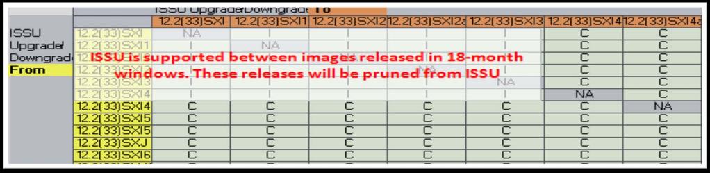
113 ISSU Compatibility Matrix on Cisco.com 120
114 VSS & EFSU Important Points EFSU supported on Sup720-10G based systems with SXI software train and newer EFSU supported on Sup2T based systems with 15.0(1)SY software and newer Dual-homed connectivity is required for minimal traffic disruption with EFSU Single-homed devices will experience an outage when the attached chassis reloads Software images files must be ISSU compatible (these are not VSS specific requirements) EFSU support begins in the SXI train Must be the same image types, meaning Native to Native or Modular to Modular For Modular images, both images must use the same installation method, therefore installed mode or binary mode The software feature sets must be the same between the two software image files 121
115 Deployment Considerations and Best Practices
116 Virtual Switching System Architecture Virtual Switch Domain A Virtual Switch Domain ID is allocated during the conversion process and represents the logical grouping the 2 physical chassis within a VSS. It is possible to have multiple VS Domains throughout the network VSS Domain 10 VSS Domain 20 VSS Domain 30 Use a UNIQUE VSS Domain-ID for each VSS Domain throughout the network. Various protocols use Domain-IDs to uniquely identify each pair. 123
117 Virtual Switching System Architecture Router MAC Address Assignment One router MAC address to represent both physical chassis as a single logical device Configuration options Burnt-In MAC address Virtual MAC address Router MAC address = 0008.e3ff.fc0a Recommendation is to use the virtual mac-address option. This eliminates the possibility of a duplicate MAC address in case the original Supervisor is ever reused within the same network. 124
118 Virtual Switching System Architecture Virtual Router MAC Address Assignment Instead of using default chassis mac-address assignment, from 12.2(33)SXH2 onwards virtual mac-address can be specified as shown below VSS(config-vs-domain)#switch virtual domain 10 VSS(config-vs-domain)#mac-address use-virtual Configured Router mac address is different from operational value. Change will take effect after config is saved and the entire Virtual Switching System (Active and Standby) is reloaded. VSS# show interface vlan 1 Vlan1 is up, line protocol is up Hardware is EtherSVI, address is 0008.e3ff.fc0a (bia 0008.e3ff.fc0a) The use-virtual MAC address is assigned from a reserved pool of MAC addresses appended with the VSS domain id. The reserved pool is 0008.e3ff.fc00 to 0008.e3ff.ffff. 125
119 Virtual Switching System Dual-Attach Whenever Possible Si Si Si Si Dual-Attach connected devices whenever possible Etherchannel and CEF hashing algorithms have been modified for VSS to always favor locally attached interfaces With a dual-attached design Data traffic will not traverse the VSL under normal conditions, only control traffic will traverse the VSL Data traffic will traverse the VSL if there is a failure event and there no local interfaces are available 126
120 VSL Bandwidth Sizing How Many Links are Needed in the VSL? Si Si Si Si The VSL is an Etherchannel Supports up to eight links Consider possible failure scenarios Fiber, SFP, Interface, Line Card, Supervisor, downstream switch interfaces Consider the bandwidth needed for any Service Modules Consider the bandwidth needed for any SPAN sessions 127
121 VSS High Availability NSF Configuration and Monitoring Router# show ip protocol *** IP Routing is NSF aware *** Routing Protocol is "eigrp " <snip> EIGRP NSF-aware route hold timer is 240s EIGRP NSF enabled EIGRP Switch(config)#router eigrp 100 Switch(config-router#nsf OSPF Switch(config)#router ospf 100 Switch(config-router#nsf Router# show ip ospf Routing Process "ospf 100" with ID Start time: 00:01:37.484, Time elapsed: 3w2d Supports Link-local Signaling (LLS) <snip> Non-Stop Forwarding enabled, last NSF restart 3w2d ago (took 31 secs) Recommendation: Non-Stop Forwarding is required for sub-sec supervisor switchover convergence with L3 Routing Protocols 128
122 VSS High Availability OOB-Mac-Synchronization Recommendation: Enable Out-Of-Band Mac-Synchronization. It is used for synchronizing mac-address tables across forwarding engines. If WS G is present in the VSS system, mac-synchronization is turned on automatically. If not it has to be enabled manually. Dist-VSS#(config)# mac-address-table synchronize % Current activity time is [160] seconds % Recommended aging time for all vlans is at least three times the activity interval Dist-VSS# show mac-address-table synchronize statistics MAC Entry Out-of-band Synchronization Feature Statistics: Switch [1] Module [4] Module Status: Statistics collected from Switch/Module : 1/4 Number of L2 asics in this module : 1 Global Status: Status of feature enabled on the switch : on Default activity time : 160 Configured current activity time : 480 If this feature is not enabled, mac-address-table across different forwarding engines could go out-of-sync and may cause unicast flooding. 129
123 Dual-Active Detection Multiple Mechanisms and Recommendations Recommendations: Use MEC with epagp or MEC with VSLP Fast Hello for faster VSL link loss convergence results. Enable BOTH epagp and direct heart-beat link based VSLP Fast Hello methods (if possible ) Enable epagp to core (if accesslayer is not epagp capable Si Si epagp Redundant VSL Fiber VSLP Fast-Hello or BFD epagp 130
, the command reload can be used to accomplish this task Virtual Switch")


124 Operational Management Reloading the VSS Should there be a requirement to reload the entire Virtual Switching System (both chassis), the command reload can be used to accomplish this task Virtual Switch vss#reload Warning: This command will reload the entire Virtual Switching System (Active and Standby Switch). Proceed with reload? [confirm] 1d04h: %SYS-5-RELOAD: Reload requested by console. Reload Reason: Reload Command. *** *** --- SHUTDOWN NOW --- *** 1d04h: %SYS-SP-5-RELOAD: Reload requested System Bootstrap, Version 8.5(1) Copyright (c) by cisco Systems, Inc. Cat6k-Sup720/SP processor with Kbytes of main memory < snip > 131

![peer shelf <1-2> vss# redundancy reload shelf 2 Reload the entire remote shelf[confirm] Preparing to](/docs-images/92/108403333/images/125-4.jpg "reload remote shelf vss# Active Hot Standby vss# redundancy force-switchover This will reload the active")
125 Operational Management Reloading a Member of the VSS NEW command has been introduced to reload a SINGLE VSS member switch Switch1 Switch2 VSL vss# redundancy reload? peer shelf <1-2> vss# redundancy reload shelf 2 Reload the entire remote shelf[confirm] Preparing to reload remote shelf vss# Active Hot Standby vss# redundancy force-switchover This will reload the active unit and Force switchover to standby [confirm] vss# 132
126 VSS Deployment Best Practices Configure Switch accept-mode virtual DO Use unique VSS domain-id within the same network Save backup configuration file in both active & hot-standby bootdisk: Use a minimum of one Supervisor uplink for the VSL, this provides for faster VSL bring up. Enable out-of-band MAC sync mac-address-table synchronize Dual-home connected devices whenever possible, use L2 or L3 Multi-Chassis Etherchannel, L3 ECMP Use epagp and VSLP Fast Hello Dual Active Protocol. Enable NSF under routing protocols 133
127 VSS Deployment Best Practices Con t DO NOT. Tune default VSLP timers unless recommended by cisco Use preemption Issue shutdown for VSL failure, it creates config mismatch. Disconnect cables to create a realistic failure scenario Change VSL hashing algorithm in production. It requires a shut/no shut on PO. Shutting down VSL will cause traffic disruption and dual-active scenario. Write-erase to reset the VSS configuration. Write-erase will erase startup-configuration and rommon variables. VSS bring-up process requires switch-id to be present in rommon variable to boot in VSS mode. Use erase-nvram instead. 134

128 Summary
129 Benefit 1: Simplifies Network Designs Build redundant topology without First Hop Redundancy Protocols No Spanning Tree blocking ports Single control plane and management interface Reduces the number of L3 routing protocol peers 136


130 Benefit 2: Scales System Capacity Groups resources together and activates all available bandwidth across redundant Cisco Catalyst 6500 switches Enables standards-based link aggregation for server NIC teaming, maximizing server bandwidth 137

131 Benefit 3: Increase Network Availability Inter-chassis Stateful Failover enables real time applications to continue without disruption Etherchannel based link resiliency provides subsecond recovery Simplifies network designs reducing human error in network operations 138
132 Reference Borderless Networks: Medium Enterprise Design Profile Campus 3.0 VSS Design Guide VSS Support Pages Cisco Catalyst 6500 Virtual Switching System Deployment Best Practices Migrate Standalone Cisco Catalyst 6500 Switch to Cisco Catalyst 6500 Virtual Switching System Troubleshoot Packet Flow in Cisco Catalyst 6500 Series Virtual Switching System 1440 VSS White Paper Catalyst 6500 Configuration Guide 139


133 BRKCRS-3468 Recommended Reading 140

 or visit one of the Internet stations throughout the Convention Center.")

134 Complete Your Online Session Evaluation Give us your feedback and you could win fabulous prizes. Winners announced daily. Receive 20 Passport points for each session evaluation you complete. Complete your session evaluation online now (open a browser through our wireless network to access our portal) or visit one of the Internet stations throughout the Convention Center. Don t forget to activate your Cisco Live Virtual account for access to all session material, communities, and on-demand and live activities throughout the year. Activate your account at the Cisco booth in the World of Solutions or visit 141
135 Final Thoughts Get hands-on experience with the Walk-in Labs located in World of Solutions, booth 1042 Come see demos of many key solutions and products in the main Cisco booth 2924 Visit after the event for updated PDFs, ondemand session videos, networking, and more! Follow Cisco Live! using social media: Facebook: Twitter: LinkedIn Group: 142


136
Advanced Enterprise Campus Design: Virtual Switching System (VSS)
") Advanced Enterprise Campus Design: Virtual Switching System (VSS) Roland Salinas Technical Marketing Engineer Housekeeping We value your feedback- don't forget to complete your online session evaluations
Advanced Enterprise Campus Design: Virtual Switching System (VSS) Roland Salinas Technical Marketing Engineer Housekeeping We value your feedback- don't forget to complete your online session evaluations
Cisco Catalyst Virtual Switching System
 Cisco Catalyst Virtual Switching System Roland Salinas Technical Marketing Engineer Key Objectives Understand the key benefits of a VSS network design Understand the VSS architecture and how a VSS behaves
Deploying Network Foundation Services
 CHAPTER 2 After designing each tier in the model, the next step in enterprise network design is to establish key network foundation technologies. Regardless of the applications and requirements that enterprises
Cisco Catalyst Virtual Switching System
 Cisco Catalyst Virtual Switching System BRKCRS-3035 Shawn Wargo Technical Marketing Engineer Agenda Why VSS? VSS Migration and Architecture Hardware and Software Requirements VSS High Availability and
VSS-Enabled Campus Design
 3 CHAPTER VSS-enabled campus design follows the three-tier architectural model and functional design described in Chapter 1, Virtual Switching Systems Design Introduction, of this design guide. This chapter
Od spanning tree ke směrování na druhé vrstvě
 Cisco Expo 2012 Od spanning tree ke směrování na druhé vrstvě T-NET4/L2 Jaromír Pilař, Consulting Systems Engineer, jpilar@cisco.com Cisco Expo 2012 Cisco and/or its affiliates. All rights reserved. Cisco
Virtual Switching System 1440 Architecture
 2 CHAPTER This chapter addresses the architecture and components of Cisco Catalyst 6500 Series Virtual Switching System (VSS) 1440. Although this design guide focuses on the deployment specifics of the
Virtual Switching System
 Virtual Switching System Q. What is a virtual switching system (VSS)? A. A VSS is network system virtualization technology that pools multiple Cisco Catalyst 6500 Series Switches into one virtual switch,
Configuring StackWise Virtual
 Finding Feature Information, page 1 Restrictions for Cisco StackWise Virtual, page 1 Prerequisites for Cisco StackWise Virtual, page 2 Information About Cisco Stackwise Virtual, page 2 Cisco StackWise
Advanced Enterprise Campus Design : Virtual Switching System (VSS)
") BRK-3035 Advanced Enterprise Campus Design : Virtual Switching System (VSS) Rahul Kachalia Enhancing Campus HA Most Common Causes of Downtime Operational Process 40% Network 20% Software Application 40%
BRK-3035 Advanced Enterprise Campus Design : Virtual Switching System (VSS) Rahul Kachalia Enhancing Campus HA Most Common Causes of Downtime Operational Process 40% Network 20% Software Application 40%
Deliver Maximum Uptime with Simplicity Using VSS Quad Supervisor RPR for Cisco Catalyst 4500-E Switches
 White Paper Deliver Maximum Uptime with Simplicity Using VSS Quad Supervisor RPR for Cisco Catalyst 4500-E Switches What Is VSS Quad Supervisor (Sup) RPR? The Cisco IOS XE 3.4.xSG software release supports
Instant Access - Virtual Switching System Hands on Lab
 Instant Access - Virtual Switching System Hands on Lab LTRCRS 2004 Vivek Baveja Sr. Technical Marketing Lila Rousseaux Consulting System Engineer Agenda Virtual Switching Systems Concepts Instant Access
Configuring Virtual Port Channels
 Configuring Virtual Port Channels This chapter describes how to configure virtual port channels (vpcs) on Cisco Nexus 5000 Series switches. It contains the following sections: Information About vpcs, page
Pass-Through Technology
 CHAPTER 3 This chapter provides best design practices for deploying blade servers using pass-through technology within the Cisco Data Center Networking Architecture, describes blade server architecture,
Migration Use Cases for Catalyst 6500 Supervisor 2T
 Migration Use Cases for Catalyst 6500 Supervisor 2T Faraz Siddiqui, Network Consulting Engineer Objectives for Understand the architectural building blocks of Supervisor 2T, hardware and software dependencies
Enterprise Multilayer and Routed Access Campus Design. Yaman Hakmi Systems Engineer
 Enterprise Multilayer and Routed Access Campus Design Yaman Hakmi Systems Engineer Agenda Multilayer Campus Design Principles Latest Cisco Campus Networking Portfolio Catalyst 6500 Nexus 7000 Routed Access
Configuring Cisco StackWise Virtual
 Finding Feature Information, page 1 Restrictions for Cisco StackWise Virtual, page 1 Prerequisites for Cisco StackWise Virtual, page 3 Information About Cisco Stackwise Virtual, page 3 Cisco StackWise
Configuring Virtual Port Channels
 This chapter contains the following sections: Information About vpcs, page 1 Guidelines and Limitations for vpcs, page 10 Configuring vpcs, page 11 Verifying the vpc Configuration, page 25 vpc Default
Cisco Catalyst 4500 E-Series High Availability
 Cisco Catalyst 4500 E-Series High Availability Introduction High availability is a critical requirement of most networks. Minimizing Ethernet switch downtime maximizes productivity for hosts and other
Layer 2 Implementation
 CHAPTER 3 In the Virtualized Multiservice Data Center (VMDC) 2.3 solution, the goal is to minimize the use of Spanning Tree Protocol (STP) convergence and loop detection by the use of Virtual Port Channel
Configuring Virtual Port Channels
 This chapter contains the following sections: Information About vpcs vpc Overview Information About vpcs, on page 1 Guidelines and Limitations for vpcs, on page 11 Verifying the vpc Configuration, on page
Cisco EXAM Cisco ADVDESIGN. Buy Full Product.
 Cisco EXAM - 352-001 Cisco ADVDESIGN Buy Full Product http://www.examskey.com/352-001.html Examskey Cisco 352-001 exam demo product is here for you to test the quality of the product. This Cisco 352-001
Configuring Virtual Port Channels
 This chapter contains the following sections: Information About vpcs, page 1 Guidelines and Limitations for vpcs, page 10 Verifying the vpc Configuration, page 11 vpc Default Settings, page 16 Configuring
Medianet Availability Design Considerations
 CHAPTER 3 The goal of network availability technologies is to maximize network uptime such that the network is always ready and able to provide needed services to critical applications, such as TelePresence
High Availability Configuration Guide, Cisco IOS XE Everest 16.6.x (Catalyst 9500 Switches)
") High Availability Configuration Guide, Cisco IOS XE Everest 16.6.x (Catalyst 9500 Switches) First Published: 2017-07-31 Last Modified: 2017-11-03 Americas Headquarters Cisco Systems, Inc. 170 West Tasman
High Availability Configuration Guide, Cisco IOS XE Everest 16.6.x (Catalyst 9500 Switches) First Published: 2017-07-31 Last Modified: 2017-11-03 Americas Headquarters Cisco Systems, Inc. 170 West Tasman
PrepKing. PrepKing
 PrepKing Number: 642-961 Passing Score: 800 Time Limit: 120 min File Version: 6.8 http://www.gratisexam.com/ PrepKing 642-961 Exam A QUESTION 1 Which statement best describes the data center core layer?
CCNP SWITCH (22 Hours)
") CCNP SWITCH 642-813 (22 Hours) Chapter-1 Enterprise Campus Network Design 1.1 IIN & SONA 1.2 Campus Network 1.3 Enterprise Model 1.4 Nonhierarchical Network Devices Layer-2 Switching, Layer-3 Routing Multilayer
CCNP SWITCH 642-813 (22 Hours) Chapter-1 Enterprise Campus Network Design 1.1 IIN & SONA 1.2 Campus Network 1.3 Enterprise Model 1.4 Nonhierarchical Network Devices Layer-2 Switching, Layer-3 Routing Multilayer
Massimiliano Sbaraglia
 Massimiliano Sbaraglia Printer Layer 2 access connections to End-Point Layer 2 connections trunk or layer 3 p2p to pair distribution switch PC CSA PVST+ or MST (Spanning Tree Protocol) VLANs LapTop VoIP
Configuring Virtual Switching Systems
 5 CHAPTER This chapter describes how to configure a virtual switching system (VSS) for the Catalyst 4500/4500X series switch (Supervisor Engine 7-E, Supervisor Engine 7L-E, and Catalyst 4500-X). Cisco
Prostředky návrhu a zajištění dostupné LAN sítě
 Prostředky návrhu a zajištění dostupné LAN sítě TECH-LANWAN Radek Boch Cisco Systems Engineer CCIE#7095 rboch@cisco.com Todays Agenda Designing High Availability Switching Networks for the Enterprise System
Cisco CISCO Data Center Networking Infrastructure Design Specialist. Practice Test. Version
 Cisco 642-971 CISCO 642-971 Data Center Networking Infrastructure Design Specialist Practice Test Version 1.1 QUESTION NO: 1 Cisco 642-971: Practice Exam Which service module configuration is recommended
examcollection.premium.exam.157q. Exam code: Exam name: Implementing Cisco IP Switched Networks. Version 15.0
 300-115.examcollection.premium.exam.157q Number: 300-115 Passing Score: 800 Time Limit: 120 min File Version: 15.0 Exam code: 300-115 Exam name: Implementing Cisco IP Switched Networks Version 15.0 Question
mls qos (global configuration mode)
") mls qos (global configuration mode) mls qos (global configuration mode) To enable the quality of service (QoS) functionality globally, use the mls qos command in global configuration mode. To disable the
mls qos (global configuration mode) mls qos (global configuration mode) To enable the quality of service (QoS) functionality globally, use the mls qos command in global configuration mode. To disable the
Describing the STP. Enhancements to STP. Configuring PortFast. Describing PortFast. Configuring. Verifying
 Enhancements to STP Describing the STP PortFast Per VLAN Spanning Tree+ (PVST+) Rapid Spanning Tree Protocol (RSTP) Multiple Spanning Tree Protocol (MSTP) MSTP is also known as Multi-Instance Spanning
Catalyst 6000/6500 Series Switches with Redundant Supervisor Engines Software Image Upgrade Configuration Example
 Catalyst 6000/6500 Series Switches with Redundant Supervisor Engines Software Image Upgrade Configuration Example Document ID: 71585 Contents Introduction Prerequisites Requirements Components Used Related
Building A Resilient Campus: Fundamentals and Best Practices
 Building A Resilient Campus: Fundamentals and Best Practices Chara Kontaxi Systems Engineer, ckontaxi@cisco.com 1 The Resilient Enterprise Campus High-Availability Design Requirements Campus network design
Configuring Private VLANs
 CHAPTER 15 This chapter describes how to configure private VLANs on the Cisco 7600 series routers. Note For complete syntax and usage information for the commands used in this chapter, refer to the Cisco
Integrated Switch Technology
 CHAPTER 2 This section discusses the following topics: Cisco Intelligent Gigabit Ethernet Switch Module for the IBM BladeCenter Cisco Gigabit Ethernet Switch Module for the HP BladeSystem Cisco Intelligent
Cisco ASR 1000 Series Aggregation Services Routers: ISSU Deployment Guide and Case Study
 Cisco ASR 1000 Series Aggregation Services Routers: ISSU Deployment Guide and Case Study In most networks, a significant cause of downtime is planned maintenance and software upgrades. The Cisco ASR 1000
Replace Supervisor Module in Cisco Catalyst 6500 Virtual Switching System 1440
 Replace Supervisor Module in Cisco Catalyst 6500 Virtual Switching System 1440 Document ID: 109334 Contents Introduction Prerequisites Requirements Components Used Conventions Configure Network Diagram
Smarter IBM Data Center for Smarter Planet. Car Mitar-Veljko IBM Hrvatska
 Smarter IBM Data Center for Smarter Planet Car Mitar-Veljko IBM Hrvatska 1 2 IBM Network Integration Services for Data Center Networks IBM Network Integration Services for data center networks provide
Symbols. Numerics INDEX
 INDEX Symbols $ matches the end of a string 7 ( ) in commands 10 * matches 0 or more sequences of a pattern 7 + matches 1 or more sequences of a pattern 7. matches any single character 7? command 1? matches
Configuring STP and RSTP
 7 CHAPTER Configuring STP and RSTP This chapter describes the IEEE 802.1D Spanning Tree Protocol (STP) and the ML-Series implementation of the IEEE 802.1W Rapid Spanning Tree Protocol (RSTP). It also explains
Network-Level High Availability
 This chapter describes Cisco NX-OS network high availability and includes the following sections: Information About, page 1 Licensing Requirements, page 2 Spanning Tree Protocol, page 2 Virtual Port Channels,
Catalyst 4500 Series IOS Commands
 CHAPTER Catalyst 4500 Series IOS Commands New Commands call-home (global configuration) call-home request call-home send call-home send alert-group call-home test clear energywise neighbors clear errdisable
Wireless Services Module 2 (WiSM2) Deployment Guide
 Deployment Guide") Wireless Services Module 2 (WiSM2) Deployment Guide Document ID: 112968 Contents Introduction Prerequisites Requirements Related Products Conventions Basic WiSM2 and Catalyst 6500 Topology Initial System
Wireless Services Module 2 (WiSM2) Deployment Guide Document ID: 112968 Contents Introduction Prerequisites Requirements Related Products Conventions Basic WiSM2 and Catalyst 6500 Topology Initial System
Building Cisco Multilayer Switched Networks (BCMSN)
") Building Cisco Multilayer Switched Networks (BCMSN) Table of Contents Module 1 Defining VLANs Implementing Best Practices for VLAN Topologies Describing Issues in a Poorly Designed Network Grouping Business
Building Cisco Multilayer Switched Networks (BCMSN) Table of Contents Module 1 Defining VLANs Implementing Best Practices for VLAN Topologies Describing Issues in a Poorly Designed Network Grouping Business
Enterprise Campus Design: Routed Access
 Enterprise Campus Design: Routed Access 2 Some Loops are Fun... 5 But Not All... Sounds Familiar...? The whole network is down %IP-4-DUPADDR: Duplicate address 10.87.1.2 on Vlan100, sourced by 00d0.04e0.63fc
Campus 3.0 Virtual Switching System Design Guide
 Campus 3.0 Virtual Switching System Design Guide Cisco Validated Design January 19, 2011 Americas Headquarters Cisco Systems, Inc. 170 West Tasman Drive San Jose, CA 95134-1706 USA http://www.cisco.com
Cisco ME 6524 Ethernet Switch
 Cisco ME 6524 Ethernet Switch Product Overview Q. What is the Cisco ME 6524 Ethernet Switch? A. The Cisco ME 6524 is a next-generation, fixed-configuration switch built for service providers Carrier Ethernet
itexamdump 최고이자최신인 IT 인증시험덤프 일년무료업데이트서비스제공
 itexamdump 최고이자최신인 IT 인증시험덤프 http://www.itexamdump.com 일년무료업데이트서비스제공 Exam : 642-813 Title : Implementing Cisco IP Switched Networks Vendor : Cisco Version : DEMO Get Latest & Valid 642-813 Exam's Question
Configuring Port Channels
 This chapter contains the following sections: Information About Port Channels, page 1, page 10 Verifying Port Channel Configuration, page 21 Verifying the Load-Balancing Outgoing Port ID, page 22 Feature
CCNA Semester 3 labs. Part 1 of 1 Labs for chapters 1 8
 CCNA Semester 3 labs Part 1 of 1 Labs for chapters 1 8 2.1.2.12 Lab - Building a Switched Network with Redundant Links 2.3.2.3 Lab - Configuring Rapid PVST+, PortFast and BPDU Guard 2.4.3.4 Lab - Configuring
Configuring Spanning Tree Protocol
 Restrictions for STP Restrictions for STP, on page 1 Information About Spanning Tree Protocol, on page 1 How to Configure Spanning-Tree Features, on page 13 Monitoring Spanning-Tree Status, on page 25
Configuring EtherChannels and Layer 2 Trunk Failover
 35 CHAPTER Configuring EtherChannels and Layer 2 Trunk Failover This chapter describes how to configure EtherChannels on Layer 2 and Layer 3 ports on the switch. EtherChannel provides fault-tolerant high-speed
CHAPTER 1 Introduction to Scaling Networks
 CHAPTER 1 Introduction to Scaling Networks As a business grows, so does its networking requirements. To keep pace with a business s expansion and new emerging technologies, a network must be designed to
Overview. Information About High Availability. Send document comments to CHAPTER
 CHAPTER 1 Cisco NX-OS is a resilient operating system that is specifically designed for high availability at the network, system, and process level. This chapter describes high availability (HA) concepts
Configuring Supervisor Engine Redundancy Using RPR and SSO on Supervisor Engine 6-E and Supervisor Engine 6L-E
 9 CHAPTER Configuring Supervisor Engine Redundancy Using RPR and SSO on Supervisor Engine 6-E and Supervisor Engine 6L-E Catalyst 4500 series switches allow a redundant supervisor engine to take over if
Question No: 1 What is the maximum number of switches that can be stacked using Cisco StackWise?
 Volume: 283 Questions Question No: 1 What is the maximum number of switches that can be stacked using Cisco StackWise? A. 4 B. 5 C. 8 D. 9 E. 10 F. 13 Answer: D Question No: 2 A network engineer wants
Configuring IEEE 802.3ad Link Bundling and Load Balancing
 Configuring IEEE 802.3ad Link Bundling and Load Balancing This document describes how the IEEE 802.3ad link bundling and load balancing leverages the EtherChannel infrastructure within Cisco software to
Configuring RPR and RPR+ Supervisor Engine Redundancy
 CHAPTER 8 Configuring RPR and RPR+ Supervisor Engine Redundancy This chapter describes how to configure supervisor engine redundancy using route processor redundancy (RPR) and RPR+. For complete syntax
Best Practices come from YOU Cisco and/or its affiliates. All rights reserved.
 Best Practices come from YOU 2 Apple iphone4 launched in June 2010 3 Antennagate 4 IPHONE4 Best Practices from CUSTOMERS 5 vpc Best Practices and Design on NXOS Nazim Khan, CCIE#39502 (DC/SP) Technical
Configuring EtherChannels and Link-State Tracking
 CHAPTER 37 Configuring EtherChannels and Link-State Tracking This chapter describes how to configure EtherChannels on Layer 2 and Layer 3 ports on the switch. EtherChannel provides fault-tolerant high-speed
squelch through system jumbomtu
 squelch through system jumbomtu squelch, page 3 srp buffer-size, page 4 srp deficit-round-robin, page 6 srp loopback, page 8 srp priority-map, page 10 srp random-detect, page 12 srp shutdown, page 14 srp
Configuring Spanning Tree Protocol
 Finding Feature Information, page 1 Restrictions for STP, page 1 Information About Spanning Tree Protocol, page 2 How to Configure Spanning-Tree Features, page 14 Monitoring Spanning-Tree Status, page
Configuring RPR Supervisor Engine Redundancy
 6 CHAPTER This chapter describes how to configure supervisor engine redundancy using route processor redundancy (RPR). For complete syntax and usage information for the commands used in this chapter, see
3. What could you use if you wanted to reduce unnecessary broadcast, multicast, and flooded unicast packets?
 Nguyen The Nhat - Take Exam Exam questions Time remaining: 00: 00: 51 1. Which command will give the user TECH privileged-mode access after authentication with the server? username name privilege level
WISM Troubleshooting. By Salil Prabhu Cisco Systems, Inc. All rights reserved. 1
 WISM Troubleshooting By Salil Prabhu 2006 Cisco Systems, Inc. All rights reserved. 1 WISM - Cisco Wireless Services Module Line Card in Cisco Catalyst 6500 Series Switch and Cisco 7600 Routers. No External
Configuring Optional STP Features
 CHAPTER 29 This chapter describes how to configure optional STP features. For complete syntax and usage information for the commands used in this chapter, see the Cisco IOS Master List, at this URL: http://www.cisco.com/en/us/docs/ios/mcl/allreleasemcl/all_book.html
Data Center Access Design with Cisco Nexus 5000 Series Switches and 2000 Series Fabric Extenders and Virtual PortChannels
 Design Guide Data Center Access Design with Cisco Nexus 5000 Series Switches and 2000 Series Fabric Extenders and Virtual PortChannels Updated to Cisco NX-OS Software Release 5.1(3)N1(1) Design Guide October
Catalyst 4500 Series IOS Commands
 CHAPTER Catalyst 4500 Series IOS Commands New Commands dot1x guest-vlan supplicant ip dhcp snooping information option allow-untrusted port-security mac-address port-security mac-address sticky port-security
Configuring VLANs. Understanding VLANs CHAPTER
 CHAPTER 12 This chapter describes how to configure normal-range VLANs (VLAN IDs 1 to 1005) and extended-range VLANs (VLAN IDs 1006 to 4094) on the switch. It includes information about VLAN membership
Describing the STP. 2003, Cisco Systems, Inc. All rights reserved. 2-1
 Describing the STP 2003, Cisco Systems, Inc. All rights reserved. 2-1 IEEE Documents IEEE 802.1D IEEE 802.1Q IEEE 802.1w IEEE 802.1s - Media Access Control (MAC) bridges - Virtual Bridged Local Area Networks
Cisco. Exam Questions SWITCH Implementing Cisco IP Switched Networks. Version:Demo
 Cisco Exam Questions 300-115 SWITCH Implementing Cisco IP Switched Networks Version:Demo 1. Which type of information does the DHCP snooping binding database contain? A. untrusted hosts with leased IP
Download: PT-Topology-STP2.pkt
 IEEE Documents Describing the STP IEEE 802.1D IEEE 802.1Q IEEE 802.1w IEEE 802.1s - Media Access Control (MAC) bridges - Virtual Bridged Local Area Networks - Rapid Reconfiguration (Supp. to 802.1D) -
Cisco 4-Port and 8-Port Layer 2 Gigabit EtherSwitch Network Interface Module Configuration Guide for Cisco 4000 Series ISR
 Cisco 4-Port and 8-Port Layer 2 Gigabit EtherSwitch Network Interface Module Configuration Guide for Cisco 4000 Series First Published: 2015-04-06 Last Modified: 2017-12-21 Cisco 4-Port and 8-Port Layer
VPC & VSS: Operation and Troubleshooting BRKCRS-1930
 VPC & VSS: Operation and Troubleshooting BRKCRS-1930 VSS and VPC enable us to build EtherChannel to 2 separate switches and transform network building block from this to this or, logically No blocked ports,
Configuring Rapid PVST+ Using NX-OS
 Configuring Rapid PVST+ Using NX-OS This chapter describes how to configure the Rapid per VLAN Spanning Tree (Rapid PVST+) protocol on Cisco NX-OS devices. This chapter includes the following sections:
Cisco Implementing Cisco IP Switched Networks. Version: 10.0
 Cisco 300-115 Implementing Cisco IP Switched Networks Version: 10.0 Topic 1, Layer 2 Technologies Cisco 300-115 Exam QUESTION NO: 1 What is the maximum number of switches that can be stacked using Cisco
Question No : 1 Which three options are basic design principles of the Cisco Nexus 7000 Series for data center virtualization? (Choose three.
 Volume: 162 Questions Question No : 1 Which three options are basic design principles of the Cisco Nexus 7000 Series for data center virtualization? (Choose three.) A. easy management B. infrastructure
Configuring Cisco NSF with SSO Supervisor Engine Redundancy
 CHAPTER 9 Configuring Cisco NSF with SSO Supervisor Engine Redundancy This chapter describes how to configure supervisor engine redundancy using Cisco nonstop forwarding (NSF) with stateful switchover
examcollection.premium.exam.191q
 300-115.examcollection.premium.exam.191q Number: 300-115 Passing Score: 800 Time Limit: 120 min File Version: 10.0 300-115 Implementing Cisco IP Switched Networks Version 10.0 Sections 1. Layer 2 Technologies
Resilient Ethernet Protocol (REP)
") The is a Cisco proprietary protocol that provides an alternative to the Spanning Tree Protocol (STP). REP provides a way to control network loops, handle link failures, and improve convergence time. It
The is a Cisco proprietary protocol that provides an alternative to the Spanning Tree Protocol (STP). REP provides a way to control network loops, handle link failures, and improve convergence time. It
Configuring the Catalyst 3750G Integrated Wireless LAN Controller Switch
 APPENDIXA Configuring the Catalyst 3750G Integrated Wireless LAN Controller Switch The Catalyst 3750G Integrated Wireless LAN Controller Switch is an integrated Catalyst 3750 switch and Cisco 4400 series
Managing Switch Stacks
 Finding Feature Information, page 1 Prerequisites for Switch Stacks, page 1 Restrictions for Switch Stacks, page 2 Information About Switch Stacks, page 2 How to Configure a Switch Stack, page 14 Troubleshooting
Describing the STP. IEEE Documents. Download this file. Enhancements to STP. Download: PT-Topology-STP2.pkt STP
 IEEE Documents IEEE 802.1D IEEE 802.1Q IEEE 802.1w IEEE 802.1s - Media Access Control (MAC) bridges - Virtual Bridged Local Area Networks - Rapid Reconfiguration (Supp. to 802.1D) - Multiple Spanning Tree
Configuring STP. Understanding Spanning-Tree Features CHAPTER
 CHAPTER 11 This chapter describes how to configure the Spanning Tree Protocol (STP) on your switch. For information about the Rapid Spanning Tree Protocol (RSTP) and the Multiple Spanning Tree Protocol
Enterprise Campus Design: Routed Access
 Enterprise Campus Design: Routed Access Tyler Creek, Communications Architect Housekeeping We value your feedback- don't forget to complete your online session evaluations after each session & complete
mail-server through service image-version efsu
 mail-server, on page 2 mdr download reserve memory image, on page 4 mls ip multicast sso, on page 6 mode (redundancy), on page 8 monitor event-trace sbc (EXEC), on page 10 monitor event-trace sbc (global),
Configuring Port Channels
 CHAPTER 5 This chapter describes how to configure port channels and to apply and configure the Link Aggregation Control Protocol (LACP) for more efficient use of port channels using Cisco Data Center Network
Configuring RPR Supervisor Engine Redundancy
 CHAPTER 7 This chapter describes how to configure supervisor engine redundancy using route processor redundancy (RPR). For complete syntax and usage information for the commands used in this chapter, see
Configuring VLANs. Understanding VLANs CHAPTER
 CHAPTER 14 This chapter describes how to configure normal-range VLANs (VLAN IDs 1 to 1005) and extended-range VLANs (VLAN IDs 1006 to 4094) on the Catalyst 3750 switch. It includes information about VLAN
High Availability (AP SSO) Deployment Guide
 Deployment Guide") High Availability (AP SSO) Deployment Guide Document ID: 113681 Contents Introduction Prerequisites Requirements Components Used Conventions Topology New HA Overview HA Connectivity Using Redundant Port
High Availability (AP SSO) Deployment Guide Document ID: 113681 Contents Introduction Prerequisites Requirements Components Used Conventions Topology New HA Overview HA Connectivity Using Redundant Port
Configuring Local SPAN and ERSPAN
 This chapter contains the following sections: Information About ERSPAN, page 1 Licensing Requirements for ERSPAN, page 5 Prerequisites for ERSPAN, page 5 Guidelines and Limitations for ERSPAN, page 5 Guidelines
Interfaces for Firepower Threat Defense
 This chapter includes Firepower Threat Defense interface configuration including Ethernet settings, EtherChannels, VLAN subinterfaces, IP addressing, and more. About Firepower Threat Defense Interfaces,
Configuring EtherChannels
 Configuring EtherChannels This chapter describes how to configure EtherChannels and to apply and configure the Link Aggregation Control Protocol (LACP) for more efficient use of EtherChannels in Cisco
Configuring IEEE 802.3ad LACP EtherChannels on the Cisco MWR 2941
 29 CHAPTER Configuring IEEE 802.3ad LACP EtherChannels on the Cisco MWR 2941 Cisco MWR 2941 Release 3.5.1 and later supports IEEE 802.3ad Link Aggregation Control Protocol (LACP) EtherChannels. Note The
z/vm Development z/vm Advanced Technical Support December 01,2009 Sue Farrell Angelo Macchiano Bruce McClellan Steve Gracin . 1
 Chapter 1. z/vm Highly Available Network December 01,2009 z/vm Development Sue Farrell Angelo Macchiano Bruce McClellan z/vm Advanced Technical Support Steve Gracin. 1 1.1 Highly Available Network 1.1.1
2008 Cisco System, Inc. All rights reserved. This document is Cisco public information under limited distribution MGSCP. Technical Design Guide
 MGSCP Technical Design Guide January 2009, Version 2.2 Page 1 of 58 Table of Contents Scope and Purpose...3 Solution Overview...4 CISCO 7600 BASED SOLUTION OVERVIEW...5 Solution Building Blocks...5 EtherChannel
Configuring Rapid PVST+
 This chapter describes how to configure the Rapid per VLAN Spanning Tree (Rapid PVST+) protocol on Cisco NX-OS devices using Cisco Data Center Manager (DCNM) for LAN. For more information about the Cisco